

Energy Save AWH9-V5+, AWH13-V5+, AWH20-V5+, AWH11-V5+ User Manual
User manualUser manual
Direct-Current Frequency Conversion Heater
AWH9/11/13/20-V5+
★Before operating this product,please read the instruction carefully and
keep this manual for future use!


1.Before use
Catalogue
1.1 List of accessories
1.2 Symbol description
1.3 Safety precautions
1.4 Features and advantages
1.5 Specifications
1.6 Part name
1.7 Working principle
1.8 Water pump
2.Installation
2.1 Installation
2.2 Installation precautions
2.3 Installation of indoor unit
Outdoor installation
2.4
2.5 Wiring
2.6 Connection of refrigerant pipe
Installation of air purging valve
2.7
2.8 Water pipe connection
2.9 Air purging
2.10 Test run
methods
3
3
3
6
7
9
11
12
13
16
17
18
19
27
33
34
35
36
3.Useage
3.1 Introduction of operation panel
Parameter Setting Overview
3.2
Basic Operation
3.3
Advanced Setting
3.4
Failure code
3.5
3.6 Error code
4.Maintenance
4.1 Introduction of maintenance
4.2 Cleaning of water filter
4.3 Cleaning of plate heat exchanger
4.4
Gas charging
4.5 Condenser coil
4.6
Service of outdoor unit
4.7
Trouble shooting
5.Appendix
5.1 Outlines and dimensions
5.2 Exploded view
5.3 Wiring diagram
37
39
44
56
67
68
78
78
78
79
80
80
84
86
89
95
-2-
1.BEFORE USE
Attention
Thank you for choosing the product. In order to operate this product well and to prevent accidents
due to misoperation, please read carefully this user manual before carrying out any installation or
operation. Please pay special attention to the warning, prohibition and attention instructions. We will
continuously upgrade this user manual for better service !
1.1 List of accessories
The accessories below are delivered together with the product .
Please check in time. If there is any shortage or damage, please contact local distributor.
Name
Sealing ring
Expansion bolt
Screw
5m extention cable for sensor TH/TC/TW
12m extention cable for sensor TR
Plastic casing for sensor TR
Plastic casing for sensor TR
User manual
Copper pipe connected to pressure release valve
Mounting plate
Pressure release valve
Copper nut
Connector for pressure release valve
13m signal cable between indoor and outdoor unit
Quantity
2
2
12
3
1
1
1
1
1
1
1
1
1
1
1.2 Symbol description
The following symbols are very important. Please be sure to understand their meaning, which concerns
the product and your personal safety.
1.3 Safety precautions
CautionWarning
This appliance is not intended for use by persons, including children, with
reduced physical, sensory or mental capabilities, or lack of experience and
knowledge, unless they have been given supervision or instruction concerning
use of the appliance by a person responsible for their safety. Children should
be supervised to ensure that they do not play with the appliance.
Prohibition
-3-
1.BEFORE USE
User Ma nual
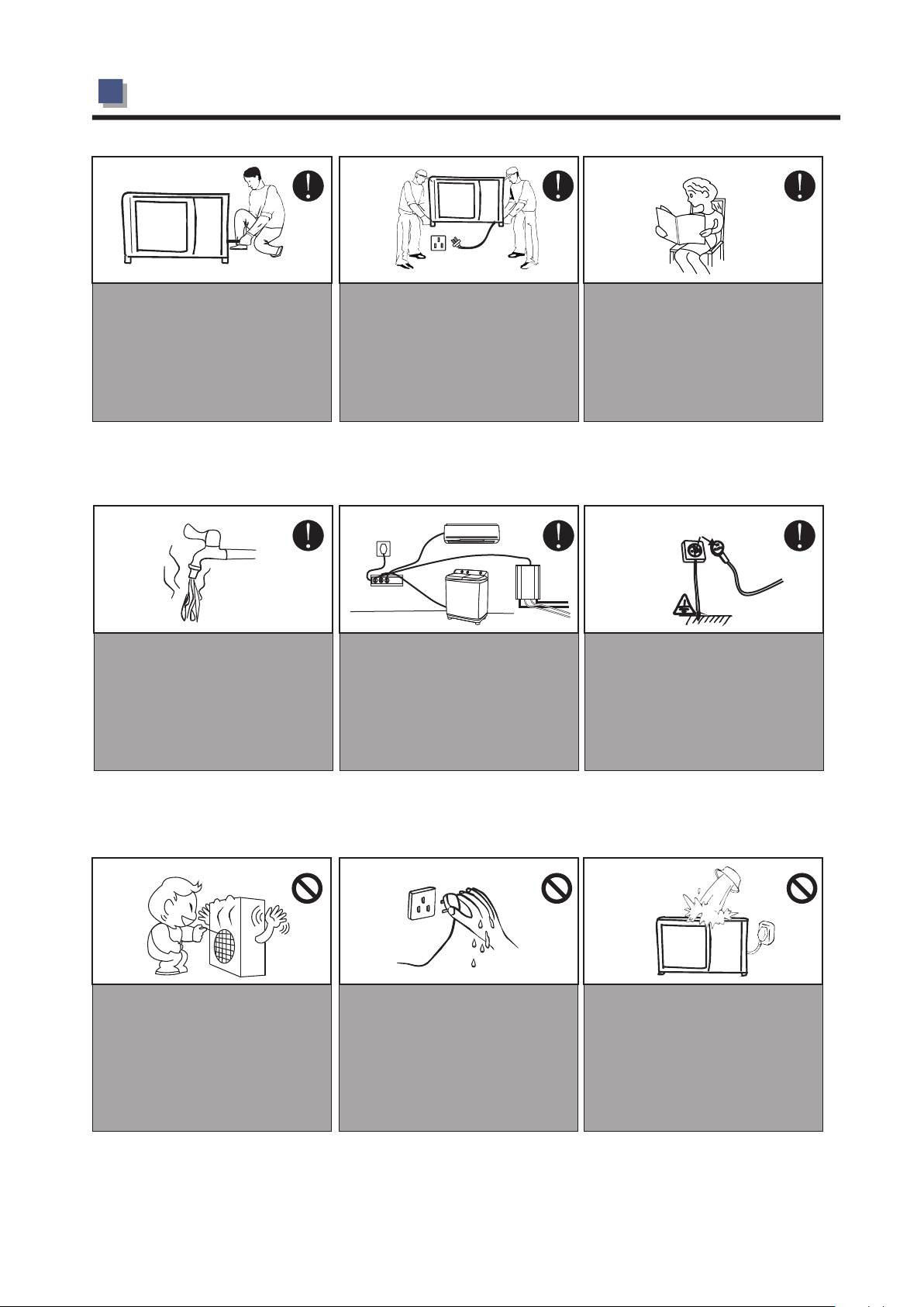
The installation, dismantlement and
maintenance of the unit must be
performed by qualified personnel.
It is forbidden to do any changes to
the structure of the unit. Otherwise
injury of person or unit damage
might happen.
Before taking shower, please always
add a mixture valve before water tap
and set it to proper temperature.
Make sure the power supply to the
heat pump unit is off before any
operations are done on the unit.
Use a dedicated socket for this unit,
otherwise malfunction may occur.
Be sure to read this manual before
use.
Ground wire
The power supply to the unit must
be grounded.
Do not touch the air outlet grill when
fan motor is running.
Do not touch the power plug with
wet hands.Never pull out the pulg
by pulling the power cable.
-4-
Water or any kind of liquid is
strictly forbidden to be poured into
the product, or may cause creepage
or breakdown of the product.
1.BEFORE USE
Steel
Copper
Fuse
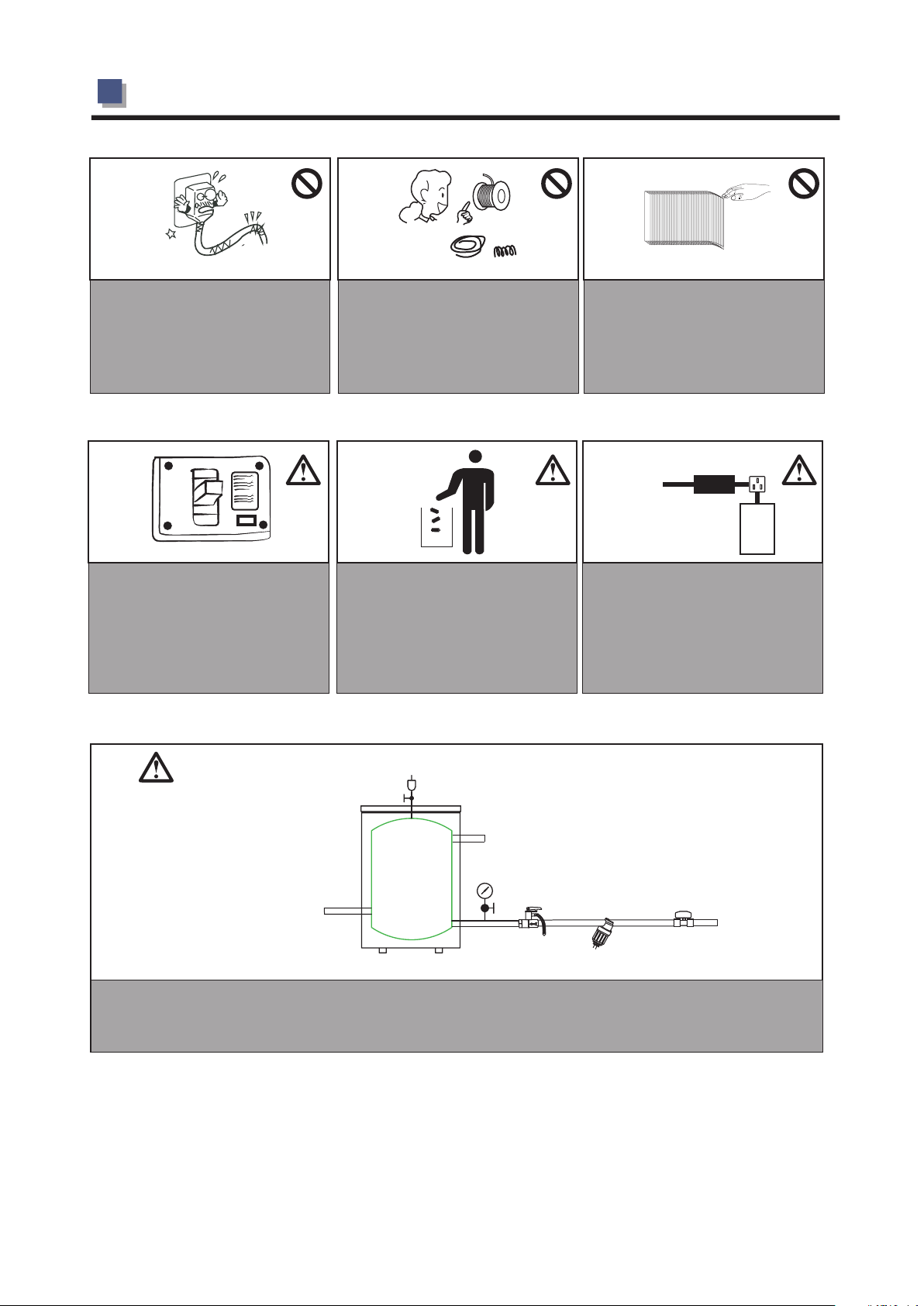
When the power cord gets loose or is
damaged, always get a qualified
person to fix it.
ON
OFF
It is mandatory to use a suitable
circuit breaker for the heat pump and
make sure the power supply to the
heater corresponds to the
specifications. Otherwise the unit
might be damaged.
Please select the correct fuse or
breaker as per recommended.
Steel wire or copper wire cannot
be taken as substitute for fuse or
breaker. Otherwise, damag ed
maybe caused.
Disposal of Scrap Batteries --Please discard the batteries as sorted
municipal waste at the accessible
collection point.
Be aware finger might be hurt by
the fin of the coil.
Main
Power Cable
Installation of a residual current
device (RCD) having a rated
residual operating current not
exceeding 30 mA is advisable.
RCD
Indoor
unit
System water filling
T/P valve
Connect to heating/cooling system
Buffer tank
Connect to heat pump
One way valve
Filter
1. It's suggested to use pure water for filling the system.
2. If use city water for filling, please soften the water and add a filter.
Note: After filling, the system of water system should be 0.15~0.6MPa.
City water inlet
-5-

1.BEFORE USE
1.4 Features and advantaged
This unit using the latest DC inverter techology.It can adjust its working frequency,so to give out
★
its output according to the loading.It can work down to -25℃ with good COP.
★ The unit is designed with easy installation that no refrigerant charging or copper pipe brazing is
required
on site.It can be widely used in house and villa.
★ The unit is with environment-friendly refrigerant R410A,which also provides one of the highest
energy effciency ratings in the industry.Output of the compressor and therefore the energy input
requirements are constantly monitored and adjusted at the most optimum level for the given
indoor and outdoor environmental conditions,and the user’s desired demands from the system.
★ Microprocessor control system contains several enhanced software features to make the
operation of the system most advantageous and pleasing,under varying environmental conditionds.
★ Special vibration absorbers on the compressor allow operation of the system with ultra low noise.
★ Microprocessor is programmed to allow operation under wide range of input voltages from
160V-260V and soft starting with lower current draw at each compressor start-up.
★ Auto-restart function keeps all settings in memory and automatically resumes the operation
after a power failure.
★ Compressor crankcase heater and bottom plate heater are available as options for extreme cold
conditions,enabling the unit to work in very low ambient temperatures with much lessened defrost
frequencies,Both these optional heaters are electronically controlled based on the outdoor ambient
temperatures and a sophisticated logic.
★ Programmable timer function provides unattended operation of the system.
★ Acrylic coated enhanced aluminum fins on the coil heat exchanger extends the fin life against
corrosion and allows easier rainwater wash-down as well as faster defrosts.
★ Copper tubing in all heat exchangers are made by the latest developments in the technology of
inner grooved tubing by extending the area of heat exchange in a more compact coil,therefore
increasing the operational efficiency.
-6-
1.BEFORE USE
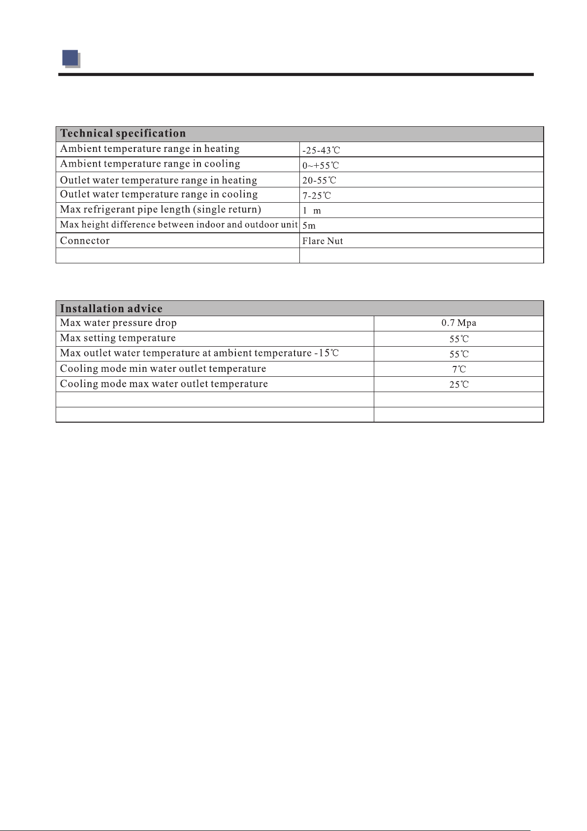
1.5 Specifications
Model AWH9 -V5+ AWH11 -V5+ AWH1 3 -V5+ AWH2 0 -V5+
Power Supply - Refrig eran t
Max. Heatin g Capaci ty
(1)
C.O.P
Heatin g Capaci ty Min./M ax.
Heatin g Power Input Min./M ax.
C.O.P Min./M ax.
Max. Heatin g Capaci ty
(2)
C.O.P
Heatin g Capaci ty Min./M ax.
Heatin g power input Min./M ax.
C.O.P Min./M ax.
Max. Coolin g Capaci ty
(3)
E.E.R
Coolin g Capaci ty Min./M ax.
Coolin g Power Input Min./M ax.
E.E.R Min./M ax.
Max. Coolin g Capaci ty
(4)
E.E.R
Coolin g Capaci ty Min./M ax.
Coolin g Power Input Min./M ax.
E.E.R Min./M ax.
(1)
(1)
(1)
(1)
(2)
(2)
(2)
(2)
(3)
(3)
(3)
(3)
(4)
(4)
(4)
(4)
Pdesig n W 6 047. 00
SCOP W/W 3.99
Compre ssor Type - Quanti ty/S ystem Twin Rotary / 1 Twin Rotary / 2
Quanti ty 1 1 2 2
Fan
Airflo w
Rated power W 76 7 6 76 x2 76x2
Noise Level Indoor /Out door dB(A ) 43/62 45/65 46/ 65 35/ 66
Wate r Side Heat
Exchan ger
Type Plate Heat Exchan ger Plate Heat Exchan ger Pl ate Heat Exchan ger Pla te Heat Exchan ger
Wate r Pressu re Drop kPa 23 23 26 35
Piping Connec tion Inch G1" G1" G1" G1 "
Allowa ble Wate r Flow Min. /Rated ./Ma x. L/S
Net Dimens ion
(L×D×H)
Packin g Dimens ion
(L×D×H)
Net Weig ht
Packin g Weig ht
Ambien t Temp . range
Outdoo r Unit mm 934X35 4X75 3 104 4X414X7 63 1124X46 0X1195 92 0X4 12X1 440
Indoor Unit mm 580X38 0X25 6.7 530X27 5X83 5
Outdoo r Unit mm 990X44 0X81 0 114 0X49 0X810 116 0X4 90X1 355 1005X5 05X1 570
Indoor Unit mm 695X45 0X31 5 620X35 0X90 5
Outdoo r Unit Kg 62. 5 7 5 113 100
Indoor Unit K g 23 39
Outdoo r Unit K g 72 .5 80 12 3 115
Indoor Unit Kg 28 42
Heatin g -25~45
Coolin g 0~55
Inlet water temp. range 10~50
Refrig eran t piping
dimens ions
Note:(1) Hea ting cond itio n: water i nlet /outlet te mper atur e: 30 /35 , Ambie nt temperatur e: DB 7 /WB 6 ;
( 2) He atin g c ondi tion: wa ter inl et/outl et tem pera ture: 40 /45 , Ambi ent tempe ratu re: DB 7 / WB 6 ;
( 3) Co olin g c ondi tion : wat er in let/ outlet temperatur e: 23 /18 , Amb ient temperatur e: DB35 /WB24 ;
( 4) Co olin g c ondi tion : wat er inlet/outl et temperat ure: 12 /7 , Am bien t tempera ture : DB3 5 /WB 24 ;
( 5) Th e spe cificat ions are subject to ch ange wi thout prior notice. Fo r act ual specificat ions of unit, please re fer to the s tickers on th e un it.
V/H z/Ph
220 - 240 /50/1 - R410A 220 - 240 /50/1 - R410A 220 - 240 /50/1 - R410A 220 -24 0/50/1 - R410A
kW 1 0.10
W/W 4.03
kW 4.33 / 10.10 4.67/11 .5 4.2/12 .6 8.6 6/20 .2
W 975/215 3 915/30 29 926/30 72 1950/4 300
11.5 12.6 20.2
3.82 3.89 4.03
W/W 4.02 / 4.65 3.82/5 .05 3.89/4 .77 4.02/4.6 5
kW 9.53
W/W 3.17
kW 4. 19 / 9.53 4.14/1 0.7 3.7 6/11.50 8 .38/ 19.06
W 1230/ 2990 1218 /362 4 1267 /3723 24 60/5 980
10.7 11.5 19.06
2.95 3.08 3.15
W/W 3.12 / 3.55 2.95/3 .56 2.9 7/3.28 3.15/3 .55
kW 6.84
W/W 2.09
kW 4. 10/ 6.84 4.33/9 .2 4. 29/10.3 7 5. 22/1 2.6
9.2 10.3 12 .6
2.68 3.29 2. 09
W 123 0 / 3280 993/346 5 957/ 3156 2460/6 650
W/W 2.09/3 .32 2.685/4 .11 3.29/4 .63 2. 09/3 .32
kW 5.05
W/W 1.58
kW 2. 34 / 5.05 2. 17/6.74 2. 34/7 .91 4. 68/10.1
6.74 7.9 10.1
2.15 2.63 1. 66
W 1 080/ 3200 924/31 32 100 0/3012 2 160/ 6400
W/W 1.58 / 2.40 2.15/ 3.0 2.33/3 .12 1. 66/2.4
8262 9556 13103
3.92 3.9 3.73
0.3
0.52 / 0.62
/
0.3
0.61 / 0.73 0.48 /0.79 /0.95
/
3
m / h
3000 3100 4200 3000x2
0.43 / 0.51
0.3
/
℃
℃
℃
Inch 3/8''~ 1/2' '
3/8''~ 1/2' ' 3 /8'' ~1/2'' 3/ 8''~ 5/8''
℃ ℃ ℃ ℃
℃ ℃ ℃ ℃
℃ ℃ ℃ ℃
℃ ℃ ℃ ℃
-7-
1.BEFORE USE
2
Safety valve release pressure
Minimum water inlet temperature in heating or hot water mode
Minimum water volume for a buffer tank
2.5 bar
23℃
60L
-8-
1.BEFORE USE
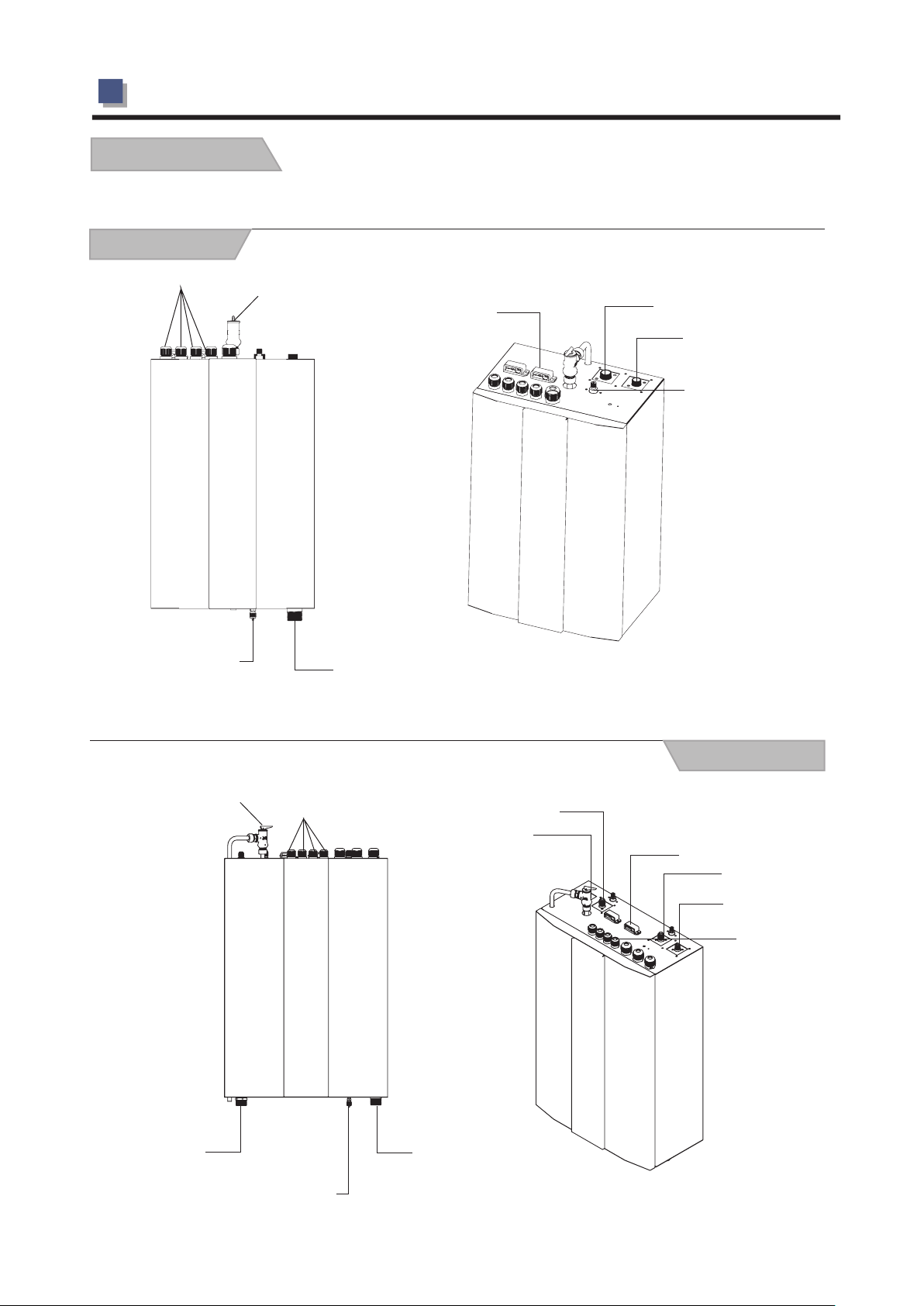
1.6 Part name
AWH9/11/13-V5+
Indoor
Cable Fixture
Needle valve for drain
Pressure release valve
Pipe Connector
Wire clip
1/2〞Connector
3/8〞Connector
Service valve
AWH20-V5+
Pressure release valve
Pipe Connector
Needle valve for drain
Cable Fixture
Indoor
1/2〞Connector
3/8〞Connector
Wire clip
1/2〞Connector
3/8〞Connector
Service valve
Pipe Connector
-9-
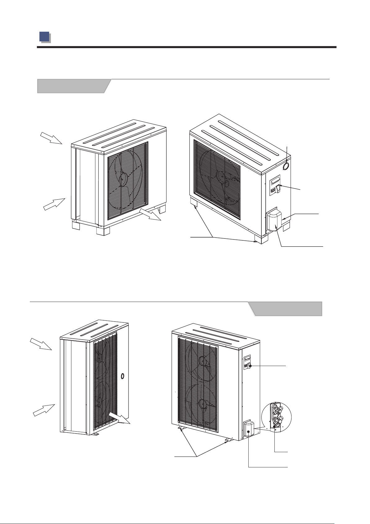
1.BEFORE USE
AW9/11-V5+
Outdoor
Air intlet
Air intlet
Pressure gauge
Handle
Pipe
Connector
AW13-V5+
Intlet
Outlet
Feet
Valve cover
Outdoor
Handle
Intlet
Outlet
Feet
-10-
Refrigerant connector
Valve cover
1.BEFORE USE
AWH20-V5+
Outdoor
Air intlet
Air intlet
Pressure gauge
Handle
Cable gland
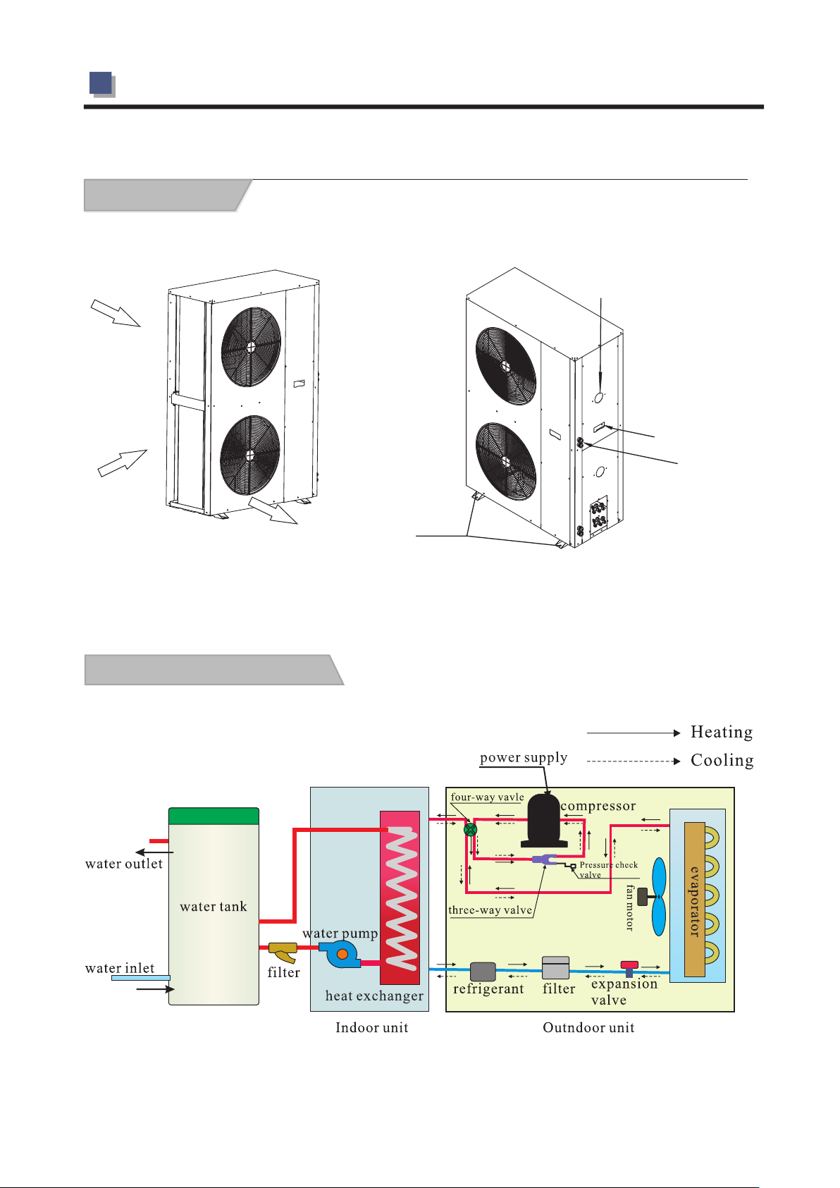
1.7 Working principle
Outlet
Feet
-11-
1.BEFORE USE
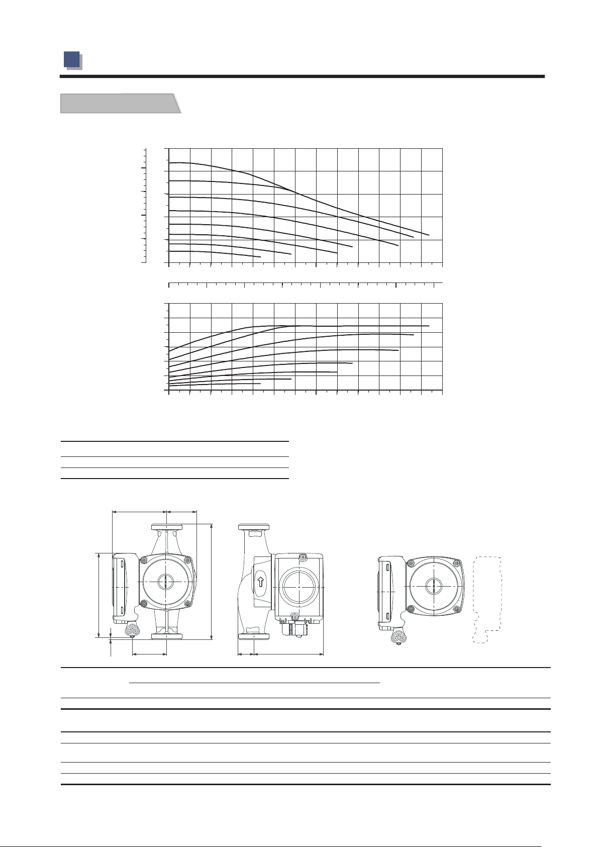
1.8 Water pump
UPM GEO 25-85 180,1X230V,50/60Hz
p
[kPa]
H
[m]
80
8
60
6
40
4
20
2
0 0
P1
0.4
0.0
0.0 0 .2
0.8
1.2
0.4
1.6
2.0
2.4 2.8
0.6
[W]
100
80
60
40
20
0
0.0
0.4
0.8
1.2
1.6
2.0
2.4 2.8
2.4 4.4
Electrical data,1X230V,50Hz
Speed P1 [W] I1/1 [A]
Min.
Max.
5.7
87
0.06
0.71
Dimensional sketches and position of control box
B3
B4
3.2 3.6 4 .0 4 .4
0.8
1.0
3.2 3.6 4 .0 4 .4
1.2
3
Q [m h]
Q [l/s]
3
Q [m h]
EEI
≤
0.23
L3
L1
L2
Pump t ype
UPM GEO 25-85 180 3.5 131 95 50 64 38 102 G11/2 2.59 160
B5
L1 L2 L3 B3 B4 B5 H1 H2
Technical data
System pressure :
Minimum inlet pressure:
Liquid temperat ure:
Motor protectio n: Overload protecti
Max. 1.0 MPa
0.05MPa (0.5 bar) at 95℃ liquid
temperature
-10
℃ to + 95 ℃ (TF 95)
H1
Dimensions [mm ]
( bar) Enclosure class: IPX4D10
on Approvals and marking: VDE, CE
H2
Connection
Insulation class:
Equipm ent class: I
Net weight
H
[kg]
Quantity per
pallet
-12-
2.INSTALLATION
2.1 Installation methods
Please observe
All drawings contains buffer tank , since this is normally used for better temperature balance form
heat pump and heating / cooling system . The sensors are therefore placed in the buffer tank . If you
don't have buffer tank in your system , the sensors needs to be put directly on the water lines . Make
sure that you get good readings by only connecting the sensors to cop per pip es or similar .
Installation drawing of unit connected directly to hea ting sy stem. (not all installers use buffer tan k).
a. With ex terna l water pump, add by pass between turn and return line between indoor unit and external
circulation pump
b. Witho ut exte rnal water pump, an adjustable bypass (ball valve) is required to ensure flow for heat pump
if thermostat close the flow in the heating system.
c. External circulation pump needs to be connecte d to indo or unit w ater pump terminal (P0)
Minimum piping dimensions required.
a. ≤ 6kW heat pump output, minimum 22 mm copper piping or similar
b. ≤ 13 kW heat pump output, minimum 28 mm copper piping or similar. For 13 kW heat pump 35 mm
copper can be required if it is much fittings and angles.
c. ≤ 20 kW heat pump output, minimum 35 mm copper piping or similar.
Please be aware of
All the sensors are put on the indoor unit . Please adjust the position o f senso rs acco rding to your
real application .
All sensors ( TW , TH and TC ) needs to be connected to the PCB to avoid failure codes , event hey
are not in use in your application .
Make sure to insulate the pipes and sensors if sensors are put direct ly on the w ater lines .
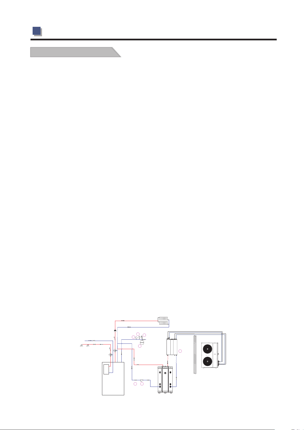
Application 1
For space heating
In this application heat pump is connected on the ret urn lin e of the heating system . The unit can be
controlled by fixed or variable water temperatu re ( curv e , based o n ambient temperature ) .
This heat pump has no internal back up , so an existing heating so urce li ke oil burner etc . needs to
be connected as back up . The installation also demand s that th e backup source have a working
controller to control the supply temperature to the heat ing sys tem . When the heating deman d
exceeds the heat pump capacity , the backup source au tomat ically starts supporting the heat pump .
This means the heat pump curve or temperature controller s hould b e set slightly above the existing
heating source controller . Then heat pump will always have the priority .
All sensors ( TW , TH and TC ) needs to be connected, even they have no function for the chosen
application. Locate water temperature senso rs on ret urn lin e if no buffer tank is installed. Mak e sure
the sensors have good contact with the pipe, and insulate th e pipes a nd sens ors.
Radiator
4
11
9
tap water
hot water supply
P
7
Indoor unit
6
Flexible
pipe 50cm
Buffer
tank
Outdoor unit
Oil fired boiler
2
1
-13-
2.INSTALLATION
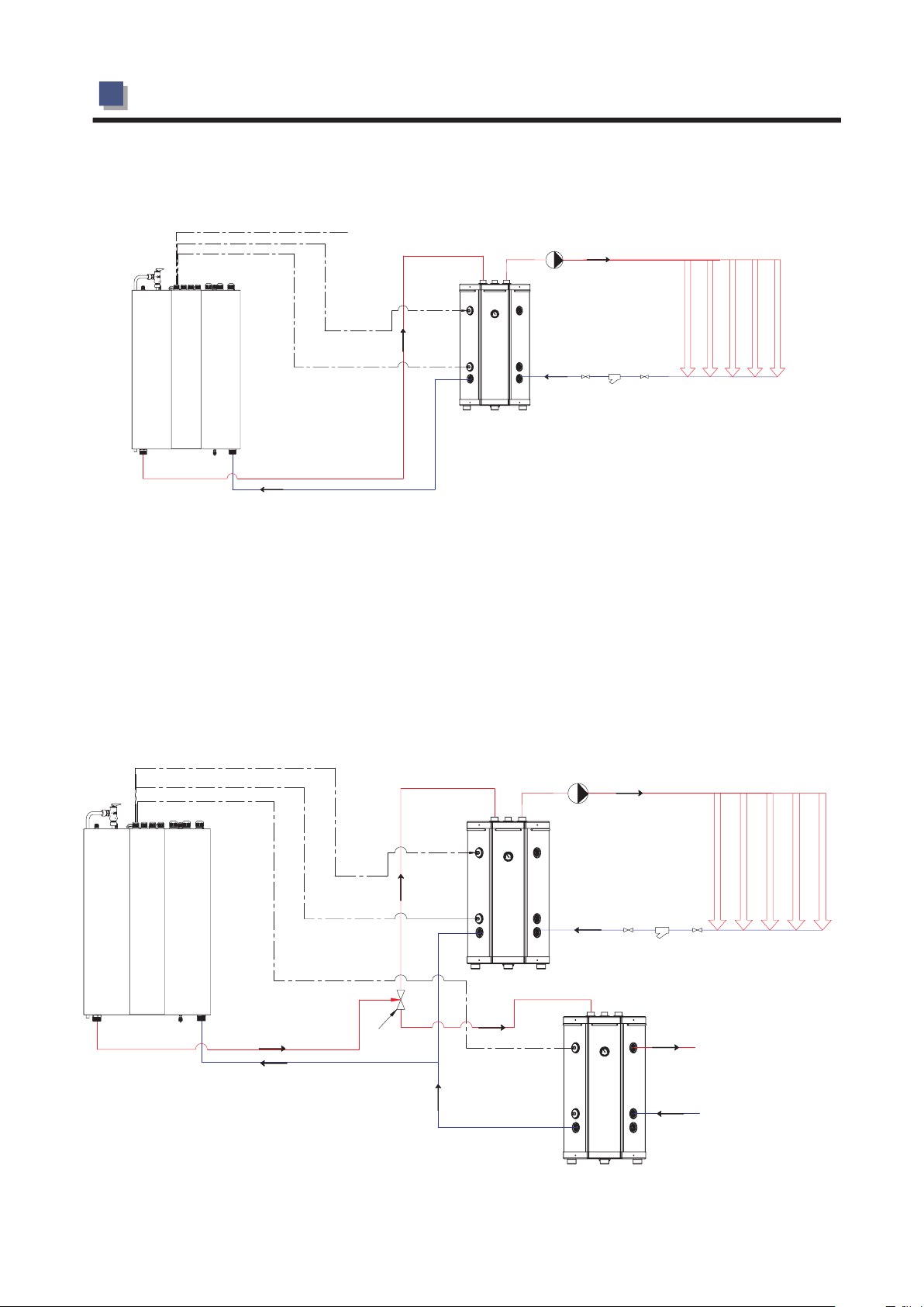
Application 2
for space heating/cooling
TW
TH
TC
Pump
Buffer
tank
Heating/Cooling
system
Place the TH (heating) sensor in the sensor pocket in the upper part of the buffer tank.
Place the TC (cooling) sensor in the sensor pocket in the lower part of the buffer tank.
If your system don' t contain a buffer tank, TH and TC sensor needs to be put directly
on the water lines. For more stable running of the heat pump, we suggest to place the
sensors on the return line and adjust the heating curve or cooling temperature accordingly
to fit the normal Delta T for your heating/ cooling system.
Heat pump setting temperature is now controlled at the actual location of these sensors.
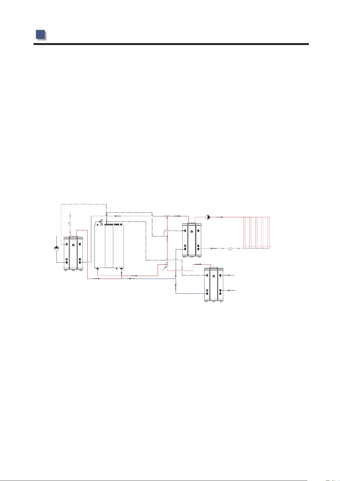
Application 3
for space heating/cooling+hot water
Changing
valve
TH
TC
TW
Pump
Bufer
tank
Heating/Cooling
system
Hot water outlet(heated
through coils in this
drawing)
City water inlet
-14-
2.INSTALLATION
This application needs a changing valve (accessories) to change the water direction according
to the set temperature for heating/cooling and hot water. Place the TH (heating) sensor in the
sensor pocket in the upper part of the buffer tank. Place the TC (cooling) sensor in the sensor
pocket in the lower part of the buffer tank. If your system don't contain a buffer tank, TH and
TC sensor needs to be put directly on the water lines. For more stable running of the heat pump,
we suggest to place the sensors on the return line and adjust the heating curve or cooling
temperature accordingly to fit the normal Delta T for your heating/cooling system.
Heat pump setting temperature is now controlled at the actual location of these sensors.
Place the TW (hot water) sensor in the upper or lower part of your accumulating water tank.
Hot water is in this system now heated through coils in the water volume. Heat pump can also
be connected to coils in a hot water storage tank (water heater). If so, it is required to have an
electric heater to increase the water temperature to 60 degrees once every week, which is
above the heat pump maximum outlet temperature of 52 degrees.
Observe: Never mix heating/cooling water and hot water.
Application 4
for space heating+cooling+hot water
TC
To fan coils
Buffer tank
Cooling
Changing
valve
TH
Pump
Buffer tank
Heating
TW
Heating system
Hot water outlet (heated
through coils in this
drawing)
City water inlet
This application needs a 2 changing valves (accessories) to change the water direction
according to the set temperature for heating, cooling and hot water. Place the TH
(heating) sensor in the sensor pocket in the upper part of the heater buffer tank. Place
the TC (cooling) sensor in the sensor pocket in the upper part of the cooling buffer tank.
If your system don' t contain buffer tanks, TH and TC sensor needs to be put directly
on the water lines. For more stable running of the heat pump, we suggest to place the
sensors on the return line and adjust the heating curve or cooling temperature
accordingly to fit the normal Delta T for your heating/cooling system.
Heat pump setting temperature is now controlled at the actual location of these sensors
.
Place the TW (hot water) sensor in the upper or lower part of your accumulating water
tank. Hot water is in this system now heated through coils in the water volume. Heat
pump can also be connected to coils in a hot water storage tank (water heater). If so,
it is required to have an electric heater to increase the water temperature to 60 degrees
once every week, which is above the heat pump maximum outlet temperature of 52
degrees.
Observe: Never mix heating/cooling water and hot water.
-15-
2.INSTALLATION
2.2 Installation precautions
1.The installation,dismantlement
and maintenance of the heat pump
must be performed by qualified
personnel.
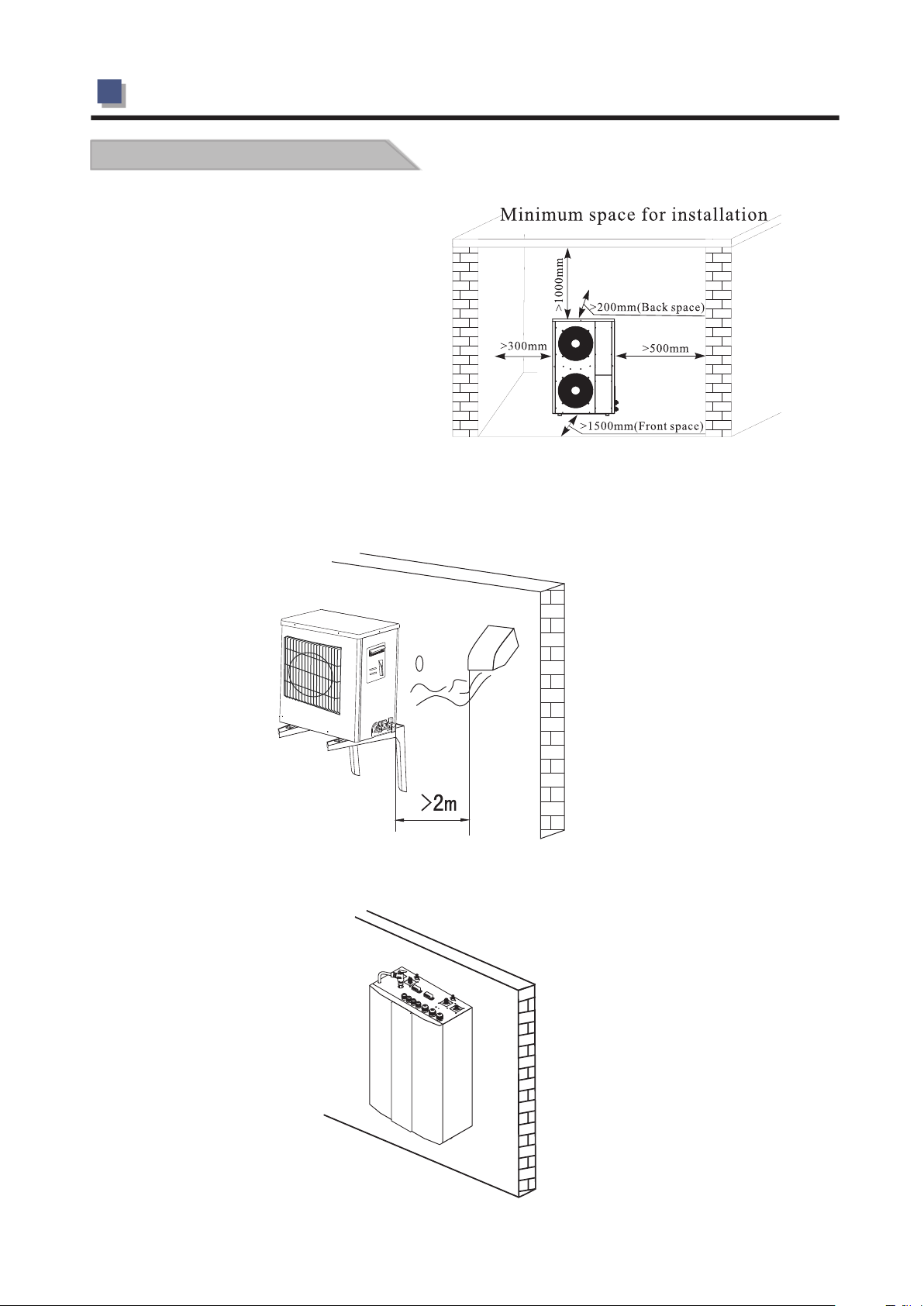
2.The unit must be installed outdoors
in an area with sufficient clearance to
provide free air citculation through
the coil.Please refer to the following
figure to choose the right place for
the unit.
3.The outdoor unit should be placed at least 2M away from the ventilation outlet of kitchen,to keep
the unit clean.
4.The indoor unit should be hung on the wall with the water connectors downwards.
-16-
2.INSTALLATION
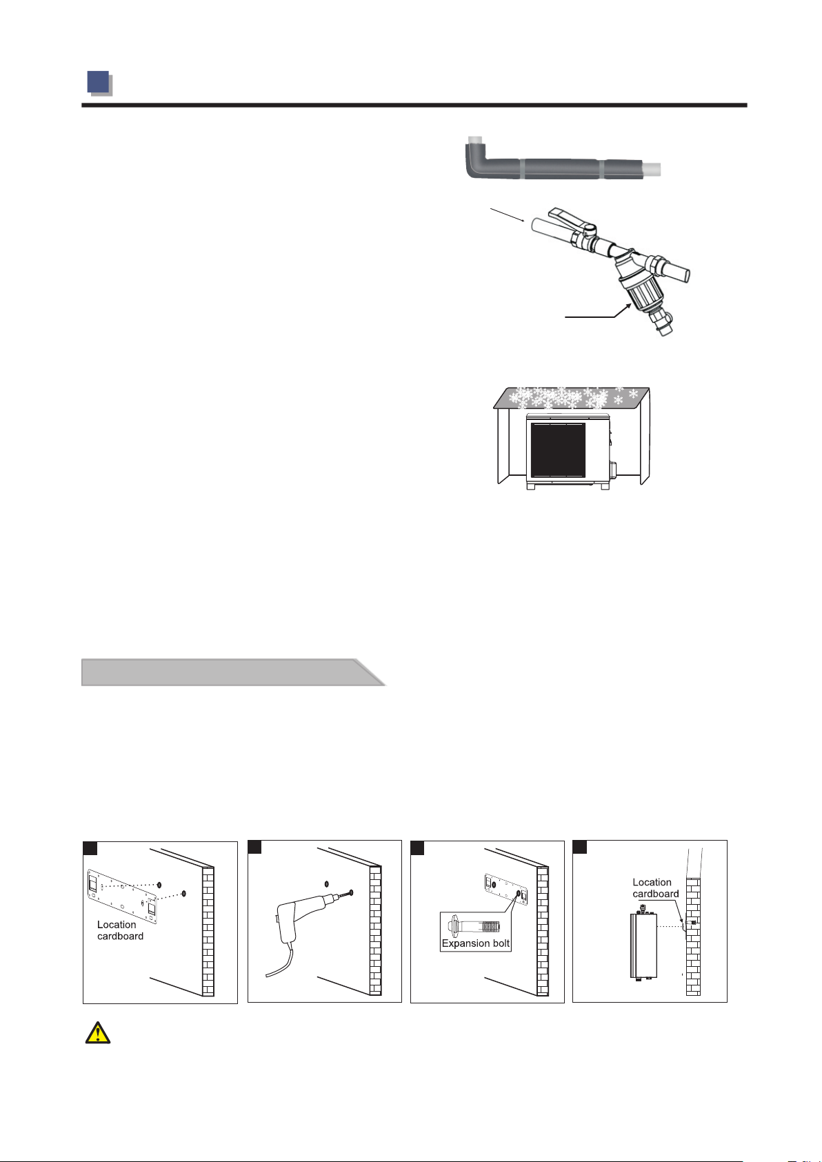
5.All the hot water pipe and water connections
should be insulated,to reduce the energy loss.
6. A mesh filter must be installed in front of the water
inlet of the unit and water tank, for keeping the
water quality and collecting impurity contained
in the water. Take care to keep the water filter
Water inlet
mesh towards the bottom. Check valve is
recommended to be installed at both sides of the
filter, so as to clean or change the filter in a easier way.
7.Shield the unit from direct sunshine,rain or snow,
but never cover the unit which will cause the bad
ventilation.
8. Install the unit and water tank close to each other as much as possible to reduce the distance
between them,so to reduce the energy loss
9.The unit should be free from corrosive and moisture surrounding.Otherwise the lifetime of the
unit might be shortened.
Filter
2.3 Installation of indoor unit
For the installation of the indoor unit, please refers to the followings:
1.Mark out the positions of the unit bracket on the wall.
2.Drill the holes on the wall.
3.Fix unit bracket with expansion bolts on the wall.
4.Then hand the indoor unit on the bracket.
1
Note:You must choose very firm wall for installation otherwise the bolts may get loose and
cause unit damage!
(refer fig.2)
(refer fig.4)
2
(refer fig.1)
(refer fig.3)
3
4
-17-
2.INSTALLATION
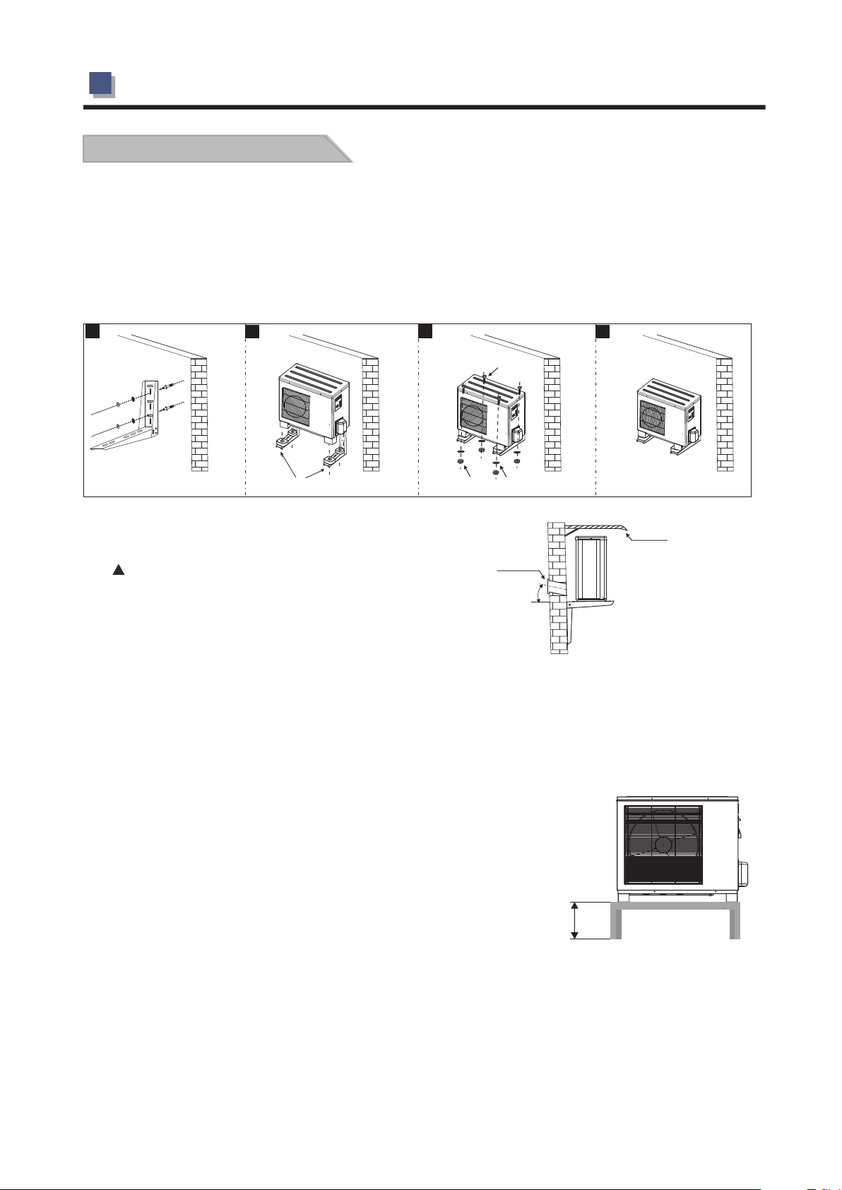
2.4 Outdoor installation
A:If needs to hang the outdoor unit on the wall, please do as followings:
1.Adjust the location of the wall according to the distance between two feet of the unit.
2.Fix the on the wall with expansion bolts.
brackets
3.Place the outdoor unit on the .A
vibration and noise.
4.Fix the unit to the bracket.
brackets
brackets Vibration absorbers are recommended to reduce
1
2
Vibrati on ab sorber
3
Bolt
Nut
Gasket
4
Shield
Sleeve
It is recommended to use a wall sleeve
to guide power cable and piping kits go
≥8°
through the wall.
B:On a concrete stand
User can either use the dedicated mounting bracket from the supplier, or prepare a suitable bracket
for the unit installation. Make sure the installation meets following requirements:
1. The unit must be installed on flat concrete blocks, or a dedicated mounting bracket. The bracket
should be able to support at least 5 times of unit’s weight.
2. All nuts must be tightened after the bracket is fixed; otherwise,
it may cause damage to the equipment;
3.User should double check and make sure the installation
of unit is firm enough.
4. The bracket can be of stainless steel, galvanized steel,
aluminum and other materials as required by the user.
5. Besides the mounting bracket, the user can also install
the outdoor unit on two concrete blocks, or a raised concrete
platform. Please make sure that the unit is securely fastened
after installation.
6.Please refer the dimension of outdoor unit when choose a suitable wall bracket.
For installation on ground where ambient temperature is below 0, use outdoor unit standings
for example the OUS35-55, in order to prevent the unit for freezing up. Concrete standings will
block the drains too much.
50cm
-18-
2.INSTALLATION
2.5 Wiring
AWH9/11/13-V5+
1.It is recommended to use a suitable breaker for the heat pump and make sure the power
supply to the heater corresponds to the specifications.Otherwise th unit might be
damaged.
2.The power supply to the heat pump unit must be grounded.
3.Cable should be fixed tightly,to ensure it won’t get lossen.
A:Main power cable
1.Main power cable has connected into the terminal block of indoor unit. Please find the cable on
top of indoor unit according to the label, and connect it to main power, as shown in the pictures below.
C
B
A
D
Main pow er in u ser side
A: Sensor cables
B: Signal cables
C: Main power cable
D: Power cable between
indoor and outdoor unit
B:Power cable between indoor and outdoor unit
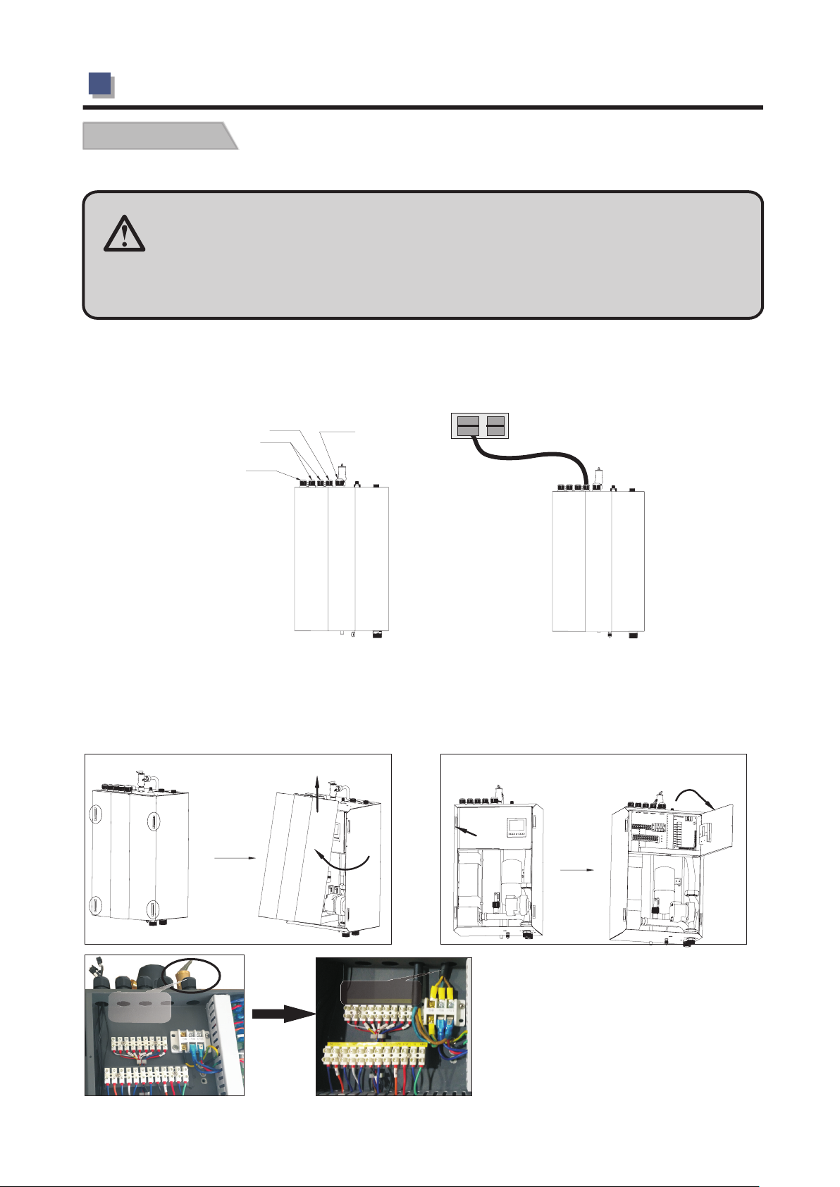
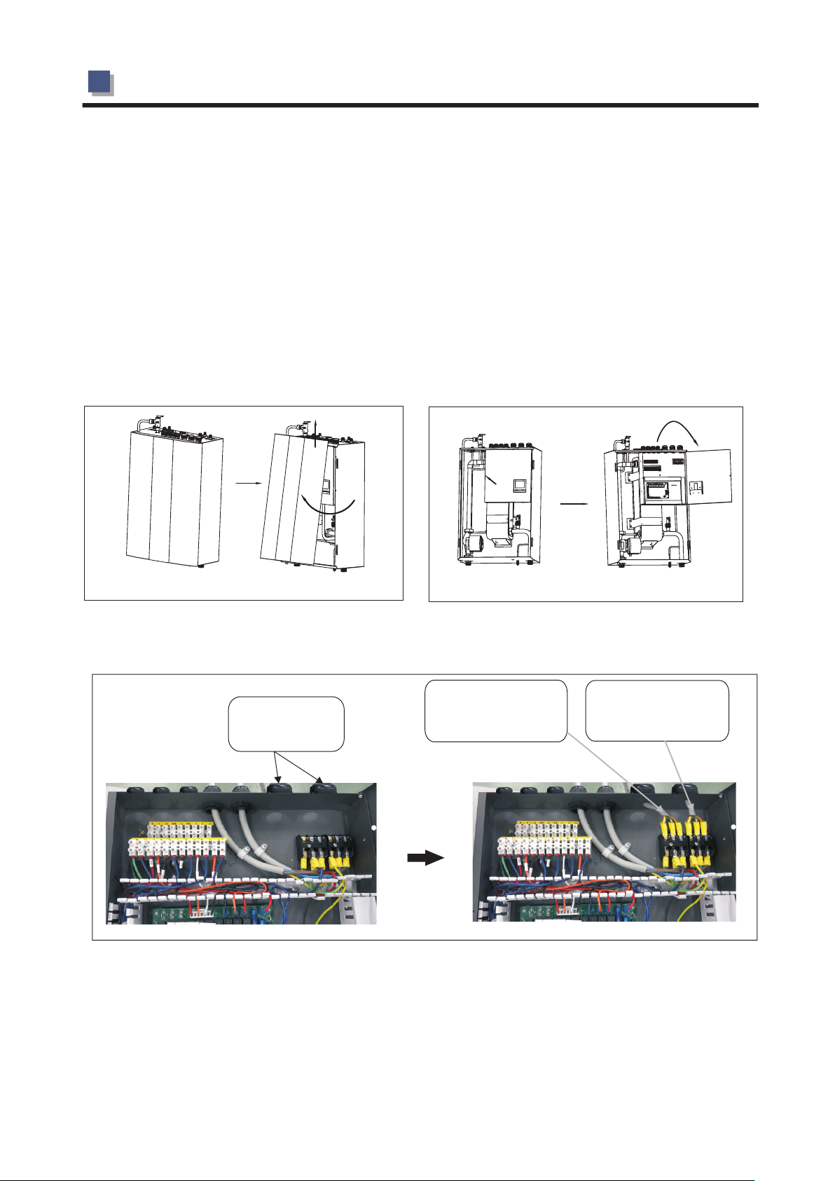
1. The indoor front panel is fixed by four magnets in two sides of door. Please take off the front panel as fig. 1.
2. Remove one screw in left side of electric box, then open the door of electric box to right side as fig. 2.
3. Prepare a power cable of 3 core 2.5mm2 and four cores with suitable length, insert the cable through
cable gland on top of the indoor unit.
Ins ert the c able
fro m this ca ble
gla nd
Fig. 1
Pow er cabl e
bet ween in door
and o utdoo r unit
Fig. 2
Fig. 3
-19-
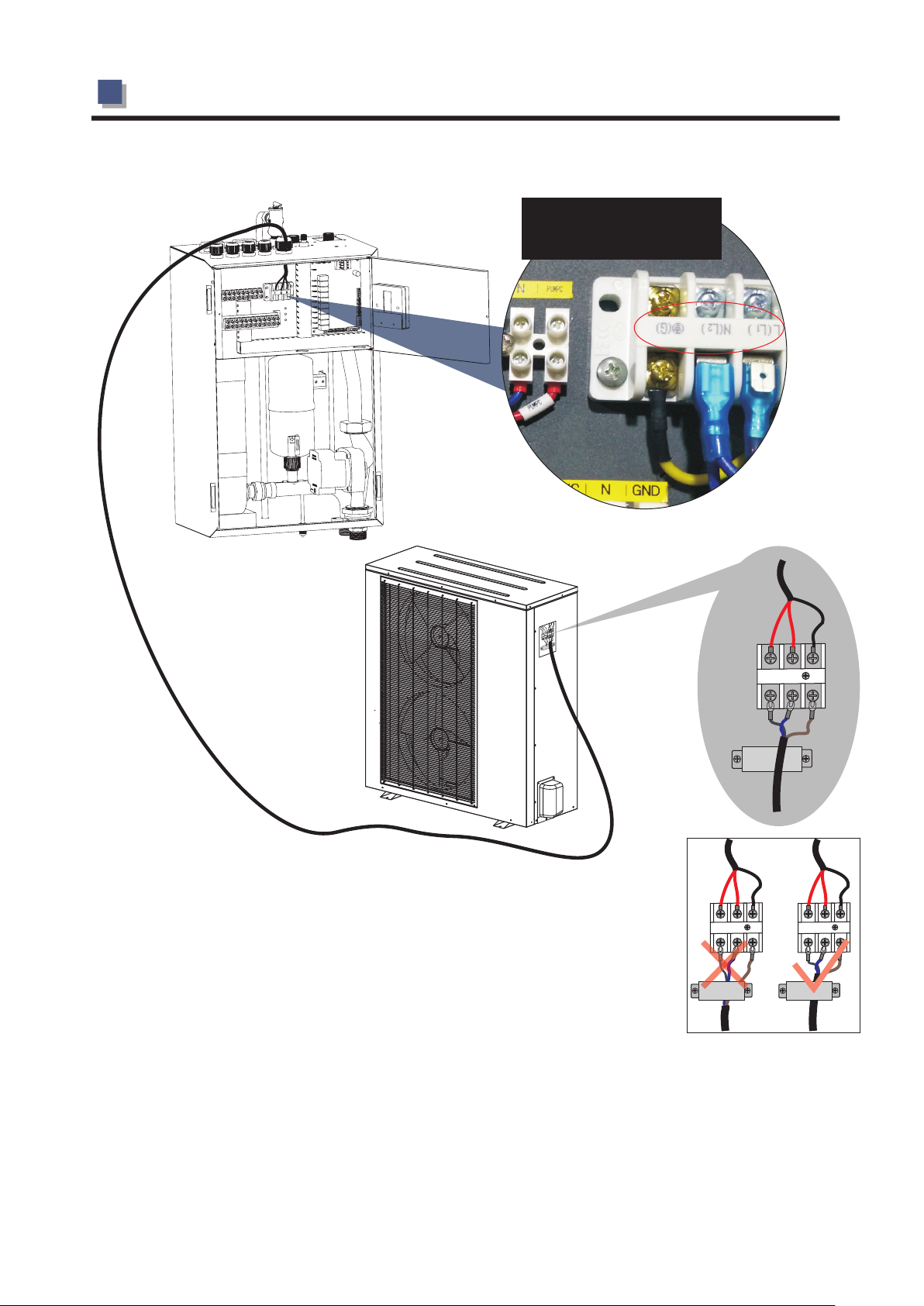
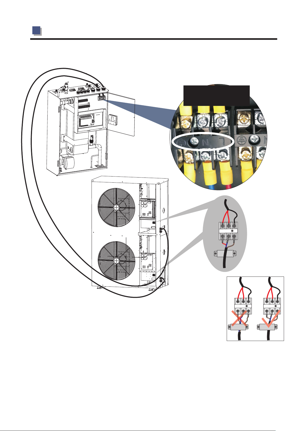
2.INSTALLATION
Shown as "L, N, G" on
wiring diagram
G N L
Notice: When fixing the power cable with the wire clip, please be careful to
clamp on the outer layer insulation, don’t clamp on the wires inside,
or it may cause damage on insulation layer of one-core wire.
4. Connect this power cable to "L,N and G" on indoor terminal block according to the wiring diagram of
indoor unit.
5. Fasten the cable gland to ensure the cable won't get loosen.
6. Connect the other side of the power cable to the outdoor unit, according to the wiring diagram. Fix the
cable with cable fixture, to ensure it won’t get loose.
-20-
2.INSTALLATION
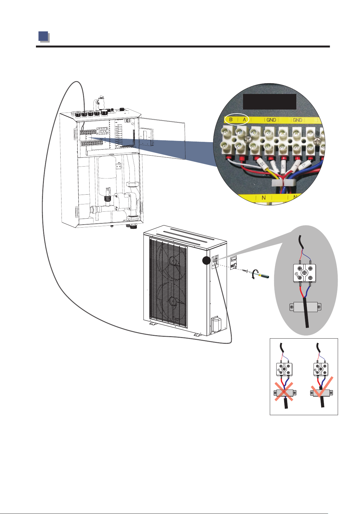
C. Signal cable between indoor and outdoor unit
Take the signal cable out from accessories bag.
corresponding
with each other
CS H S
HW
SH
ES
3
A B
Notice: When fixing the power cable with the wire clip, please be careful to
A B A B
clamp on the outer layer insulation, don’t clamp on the wires inside,
or it may cause damage on insulation layer of one-core wire.
1. Insert one end of this cable through the cable gland on top of the indoor unit, and connect this
cable to A, B on terminal block.
2. Fasten the cable gland to ensure the cable won't get loosen.
.
3 Connect the other end to the terminal block on outdoor unit. A, B on outdoor unit should be
connected with A, B on indoor unit, otherwise unit will show communication failure.
-21-
2.INSTALLATION
AWH20-V5+
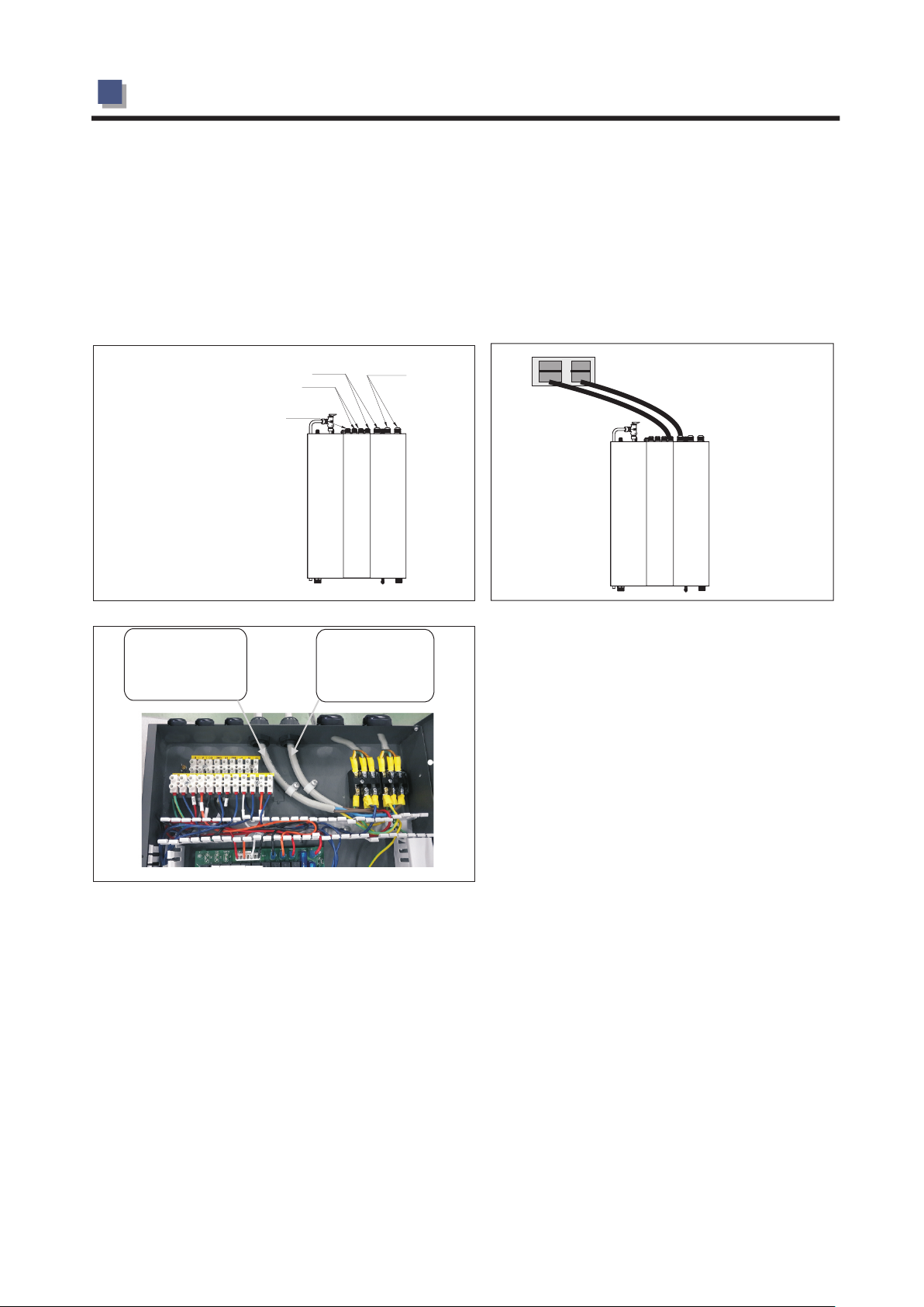
A:Main power cable
1. Main power cable has connected into the terminal block of indoor unit. Please find the cable on
top of indoor unit according to the label, and connect it to main power, as shown in the pictures
below.
A
A: Sensor cables
B: Signal cables
C: Main power cable
D: Power cable between
indoor and outdoor unit
Fig. 1
Power cable
indoor unit
for system 1
C
B
Power cable
indoor unit
for system 2
D
Main pow er in u ser side
Fig.2
Fig. 3
-22-
2.INSTALLATION
B:Power cable between indoor and outdoor unit
1. The indoor front panel is fixed by four magnets in two sides of door. Please take off the front
panel as fig. 1.
2. Remove one screw in left side of electric box, then open the door of electric box to right side
as fig.2.
3. Prepare 2 pos power cable of 3 core 2.5mm2 with suitable length, insert the cable through
cable gland on top of the indoor unit, as fig .3.
Fig. 1
Insert the cable
from this cable
gland
Power cable
betwee n ind oor
and outdoor unit ( stys tem 1)
Fig.3
Fig. 2
Power cable
between indoor
and outdoor unit ( sty ste m 2)
-23-
2.INSTALLATION
Shown as "L, N, G" on
wiring diagram
G
N
L
Notice: When fixing the power cable with the wire clip, please be careful to
clamp on the outer layer insulation, don’t clamp on the wires inside,
or it may cause damage on insulation layer of one-core wire.
2. Connect this power cable to "L,N and G" on indoor terminal block according to the wiring diagram of
indoor unit.
3. Fasten the cable gland to ensure the cable won't get loosen.
4. Connect the other side of the power cable to the outdoor unit, according to the wiring diagram. Fix the
cable with cable fixture, to ensure it won’t get loose.
-24-

2.INSTALLATION
C. Signal cable between indoor and outdoor unit
Take the signal cable out from accessories bag.
corresponding
with each other
CS H S
HW
ES
SH
A B
Notice: When fixing the power cable with the wire clip, please be careful to
A B A B
clamp on the outer layer insulation, don’t clamp on the wires inside,
or it may cause damage on insulation layer of one-core wire.
1. Insert one end of this cable through the cable gland on top of the indoor unit, and connect this
cable to A, B on terminal block.
2. Fasten the cable gland to ensure the cable won't get loosen.
3 Connect the other end to the terminal block on outdoor unit. A, B on outdoor unit should be
.
connected with A, B on indoor unit, otherwise unit will show communication failure.
-25-
2.INSTALLATION
When connecting the power cable between the outdoor unit and indoor unit, cables connected
to the terminal block in indoor unit must match these in outdoor unit.
For example, if the terminals and power cables are connected as →gree/yellow cable,
L→ red cable, N→blue cable, S→black cable in indoor unit, the connections in the outdoor
unit should be in the same way.
Installation sketch
E. Sensor cables
All temperature sensors are preinstalled in the unit, and the unit can be operated without any changes.
Still for different applications it is possible to move the sensors to the place you wish to have the units
temperature readings for the controller. For example if the unit is connected to a buffer tank or
accumulating water tank, it is more efficient to let the heat pump be controlled by the water
temperature in the water tank.
1. Disconnect the sensor with the quick connector inside the indoor unit.
2. Insert the sensor cable from indoor PCB through cable gland on top of indoor unit.
3. Connect the sensor cable which stick out on top of indoor unit with extension cable for sensor.
4. Connect the other side of extension cable with the sensor.
5. Place the sensor in right position, according to your application, as shown in the pictures below.
6.Make sure to let water temperature sensors to have good contact by using cooling past in sensor
pockets, and insulate sensors located directly on water pipes.
Sensor cables
A
Sensor cable connection
Indoor unit
Extension cable for sensor
Sensor
Place all sensors in right positions
-26-
2.INSTALLATION
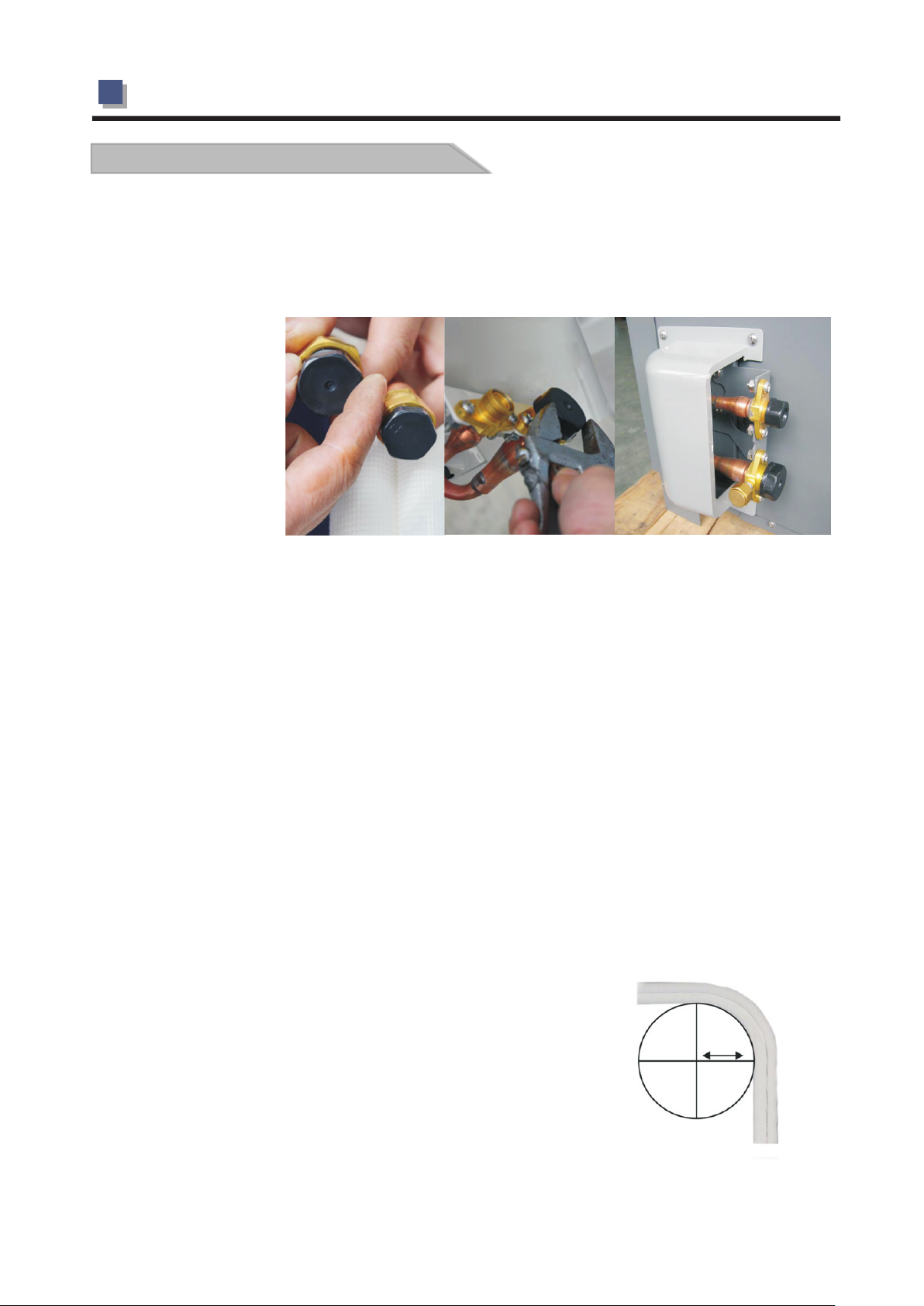
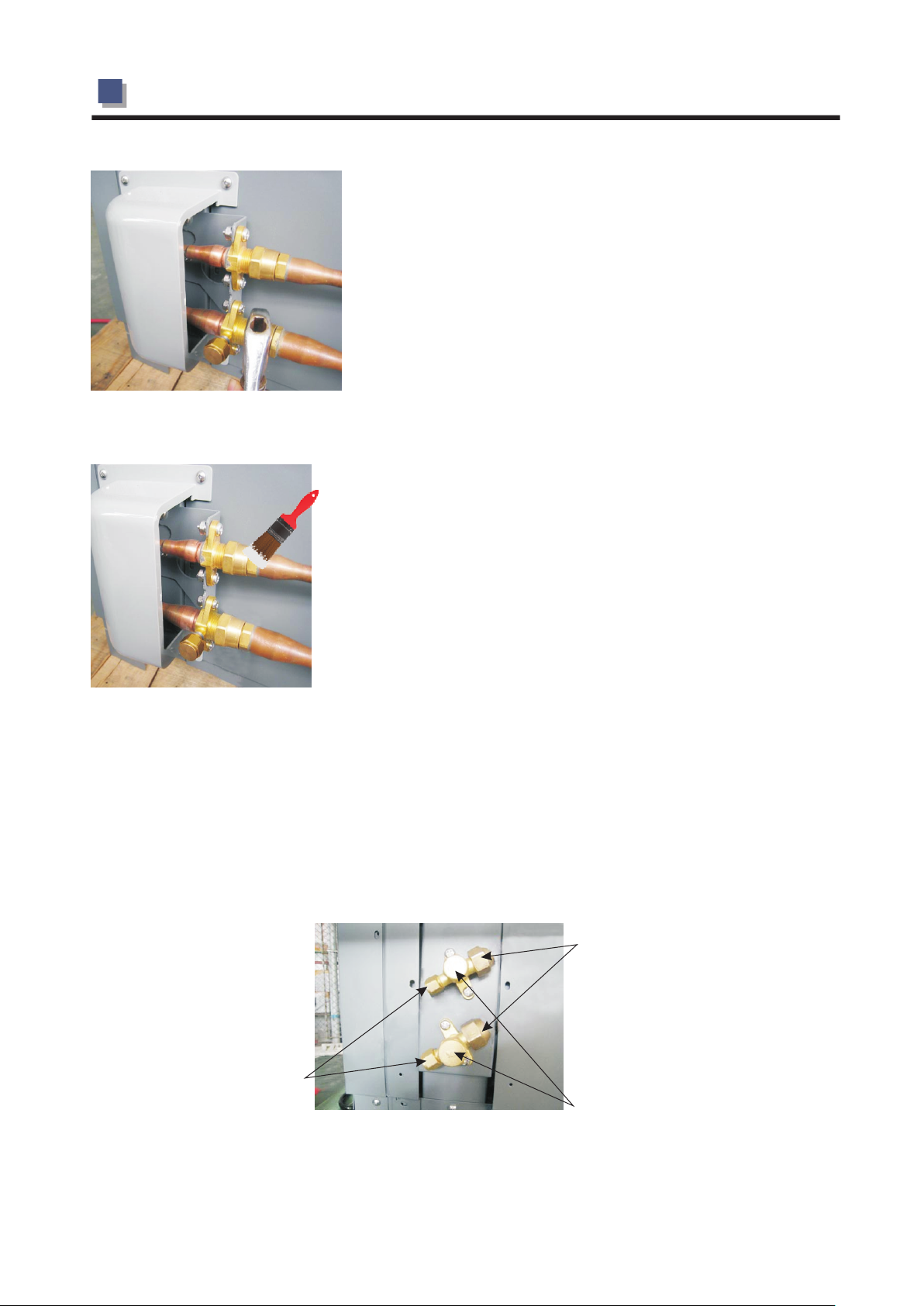
2.6 Connection of refrigerant pipe
AWH9/11/13-V5+
A:For the unit with quick connector
Begin routing from the indoor unit and straighten out the pipes as you go.On the pipe ends in the
installation kit are cap nuts for connection to the cannot be installed incorrectly.Hold the connection
in place with one spanner
and tighten the cap nut
with the other,as
otherwise the connection
can be damaged.
Conect the installation
kit’s pipes to the
connections on the indoor
unit.First screw together
the screw connections by hand and then tighten using the spanners.Tighten the connection fully
without stopping.A hissing noise can be heard.Hold the connection in place with one spanner and
tighten the cap nut with the other.Tighten to at least 18Nm.Use a torque wrench if you are unsure
Never turn the fixed connections.Use the spanner only as a counter hold during connection.If a
counter hold is not used,the connections can turn,which can destroy them.Tighten the connections
24 hours after installation has been completed.
IMPORTANT:
Note that the pipes in the installation kit are filled with gas and must not be cut under any
circumstances.
The plastic plugs on the ends of the pipe must not be removed until the pipes are to be connected.
If the pipes are bent and causing leakage, the couplings must be loosened so that the non-return
valves close.
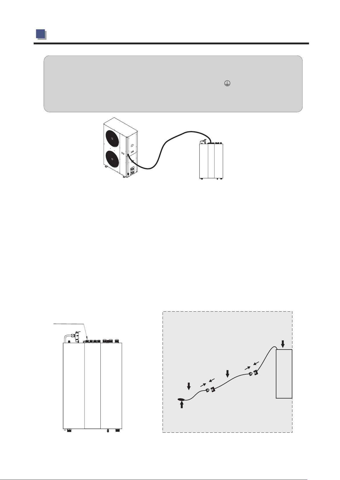
Route the pipes from the indoor unit and connect them in
the same way to the outdoor unit.
Refrigerant pipes must not be bent to a radius of less than
15cm(check with a cardboard template).Route the electrical
cable along the pipes.Bend the pipes carefully,a little at a
time.Do not bend the pipes too sharply.
-27-
Radius 15 cm
2.INSTALLATION
Connect the installation kit's pipes to the connections on the
outdoor unit.First screw together the screw connections by
hand and then tighten using the spanners.
Tighten the connection fully without stopping.A hissing noise
can be heard.Hold the connection in place with one spanner and
tighten the cap nut with the other.
Never turn the fixed connections.Use the spanner only as a
counter hold is not used,the connections can turn,which can
destroy them.Tigthen the connections 24 hours after
installation has been completed.
Check the seals and tighten the couplings again 12-24
hours after installation. Check for leaks by wetting with
soapy water. Also check the connections at the indoor unit.
If no bubbles appear, the couplings are properly connected
and tightened!
B:For the unit with flare nut connection
Note:When vacuuming the system,please don’t turn on the high/low pressure valve. Otherwise
refrigerant .leaks
Connector for
refrigerant pipe
Connector of
vacuum pump
High/Low
pressure valve
-28-
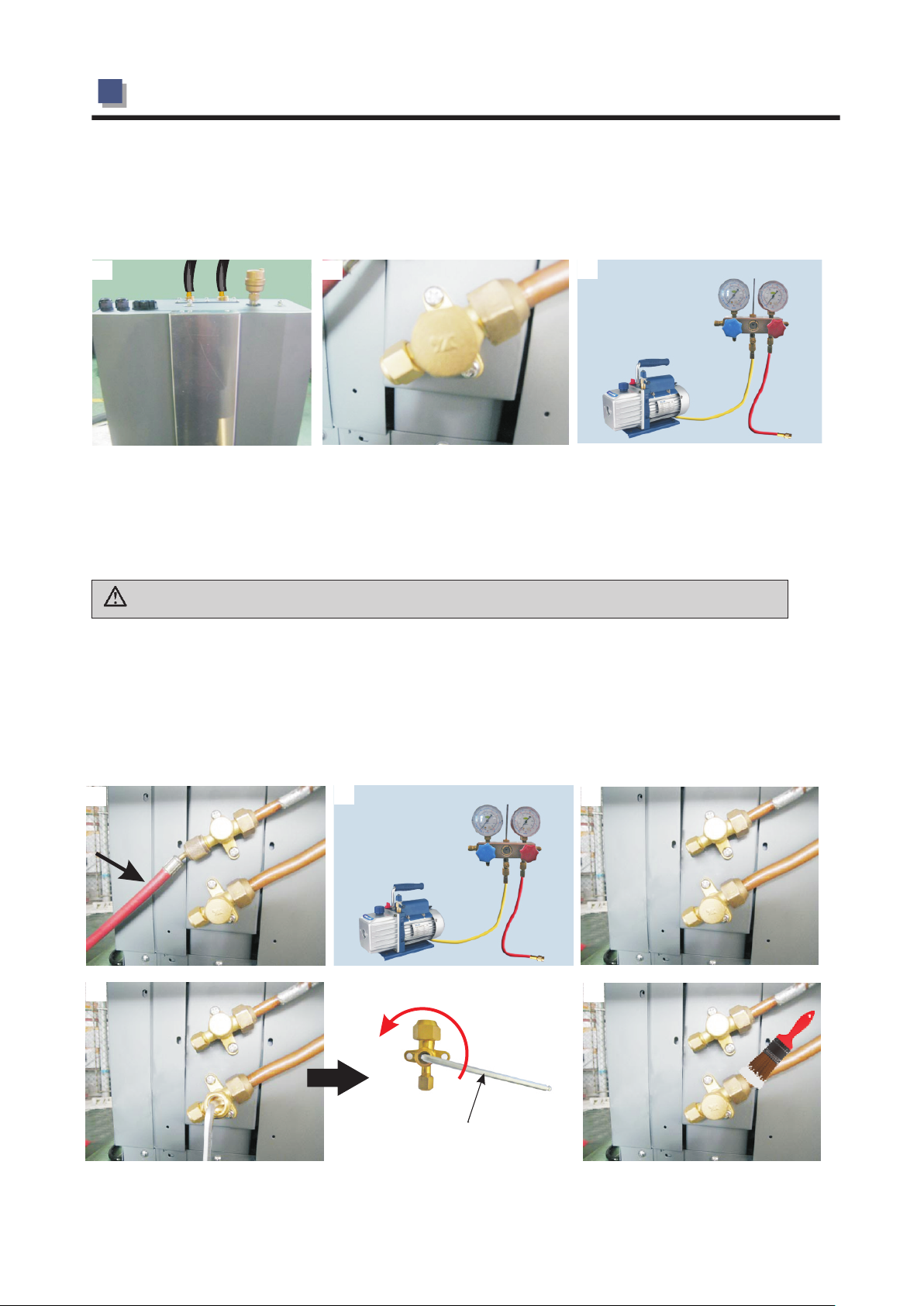
2.INSTALLATION
1.Connect the refrigerant piping to the indoor unit(refer fig.1).
2.Connect the other side of the refrigerant pipe to the the outdoor unit(refer fig.2).
3.
Prepare a vacuum pump and a pressure gauge, connect one tube of the pressure gauge to the
vacuum pump.
1
Connect the other tube of the pressure gauge to the outdoor unit.
4. (refer fig.4).
5. Open pressure gauge, and start the vacuum pump to vacuum the unit for around 10 minutes.
When the pressure gauge shows negative pressure, close the pressure gauge and stop vacuuming
(refer fig.5).
Attention:The liquid valve can't be opened until the vacuumizing has been totally finished.
6.Ture off the vacuum pump and install the cooper nut back to the high pressure connector
(refer fig.6).
(refer fig.3).
2
3
7.Use a 5mm hex wrench to open two valves on the unit as shown in the picture(refer fig.7).
8.
Check with leakage detector or soap water if there is any leakage. If not , then put back the copper
nuts onto the valves
4
7
(refer fig.8).
5
Hexagon Spanner M5:
In counter-clockwise
direction
6
8
-29-
 Loading...