

Page 1
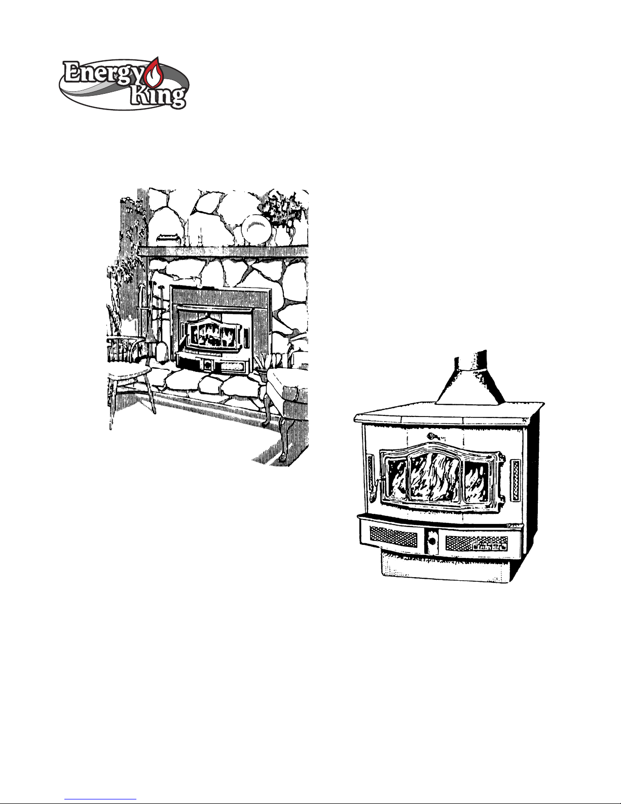
Bay 2000C Fireplace Insert & Freestanding Stove
Installation, Operation and Maintenance Instructions
Fireplace Inserts
Safety and emissions tested at Intertek Testing Services, Middleton, Wisconsin, to the appropriate standards for the
U.S. – to UL 127 for inserts and UL 1482 for freestanding models.
RJM Manufacturing, Inc.
PO Box 27 ♦ 1875 Olson Drive
Chippewa Falls, WI 54729
(715) 720-1794 ♦ Fax (715) 720-1797
Freestanding Stoves
Page 2

Congratulations on your purchase of an Energy King solid fuel appliance. Your stove or
insert is designed for a lifetime of durable, reliable performance and easy operation.
This manual describes the installation and operation of the Energy King Bay 2000C
freestanding stove and fireplace insert models. These heaters are tested to EPA
Certification for emissions.
If this stove is not properly installed, a house fire may result.
For your safety, follow the installation directions. Contact local
building or fire officials about restrictions and installation
inspection requirements in your area. You will also need to
determine if you are required to obtain a permit from the local
governing authority.
Please read this entire manual before you install and use your
new stove. Failure to follow instructions may result in property
damage, bodily injury, or even death.
Please keep this manual in a safe place for future reference.
Table of Contents
SAFETY NOTES – IMPORTANT.....................................................................................................................1
COMPONENTS...................................................................................................................................................2
INSTALLATION MATERIALS NEEDED FOR YOUR SAFETY................................................................3
FLOOR PROTECTOR........................................................................................................................................3
FIREPLACE INSERT INSTALLATION..........................................................................................................3
S
PECIFICATIONS – MODEL BAY 2000C.............................................................................................................3
LEARANCES TO COMBUSTIBLES ......................................................................................................................4
C
ENTING SYSTEM...............................................................................................................................................5
V
ONNECTION TO A MASONRY FIREPLACE.........................................................................................................6
C
EFORE INSTALLATION.......................................................................................................................................6
B
OUNT TRIM PANELS ........................................................................................................................................7
M
RASS TRIM .......................................................................................................................................................7
B
IRECT CONNECT ..............................................................................................................................................7
D
Rev 4/2006
Page 3

FREESTANDING STOVE INSTALLATION ..................................................................................................8
S
PECIFICATIONS – MODEL BAY 2000C.............................................................................................................8
ASE ASSEMBLY ................................................................................................................................................9
B
LUE ADAPTOR ..................................................................................................................................................9
F
LEARANCES TO COMBUSTIBLES ....................................................................................................................10
C
LOOR PROTECTOR.........................................................................................................................................10
F
ENTING SYSTEM.............................................................................................................................................11
V
HIMNEY CONNECTOR.....................................................................................................................................11
C
IRESTOPPING..................................................................................................................................................13
F
HIMBLE............................................................................................................................................................14
T
RICK CHIMNEY THIMBLE ASSEMBLY..............................................................................................................15
B
WARNINGS........................................................................................................................................................18
D
O NOT BURN..................................................................................................................................................18
ACKPUFFING...................................................................................................................................................18
B
VERFIRE.........................................................................................................................................................18
O
OPERATING YOUR ENERGY KING............................................................................................................19
W
HAT IS A CATALYTIC WOODSTOVE?.............................................................................................................19
SING YOUR CATALYTIC WOODSTOVE...........................................................................................................19
U
ROUBLESHOOTING YOUR CATALYTIC COMBUSTOR......................................................................................20
T
EPLACING YOUR CATALYTIC COMBUSTOR ...................................................................................................21
R
BURNING YOUR ENERGY KING STOVE..................................................................................................22
OPERATING THE CIRCULATING BLOWER............................................................................................23
WOOD.................................................................................................................................................................24
MAINTAINING YOUR ENERGY KING.......................................................................................................24
D
ISPOSAL OF ASHES........................................................................................................................................24
REOSOTE – FORMATION AND NEED FOR REMOVAL......................................................................................25
C
ARE OF GLASS...............................................................................................................................................25
C
ARE OF BRASS DOORS..................................................................................................................................25
C
ARE OF BLOWER............................................................................................................................................25
C
ASKET REPLACEMENT...................................................................................................................................26
G
TROUBLESHOOTING GUIDE.......................................................................................................................27
U
NIT DOES NOT BURN PROPERLY ....................................................................................................................27
NIT DOES NOT GIVE OFF ENOUGH HEAT.........................................................................................................27
U
NIT IS MAKING NOISE/DISTRIBUTION BLOWER IS VIBRATING..........................................................................28
U
LOWER IS NOT WORKING................................................................................................................................28
B
SE AND MAINTENANCE OF A CATALYST ........................................................................................................29
U
REQUENTLY ASKED QUESTIONS.....................................................................................................................30
F
Rev 4/2006
Page 4

SAFETY NOTES – IMPORTANT
1. Never use gasoline or similar liquids to start or “freshen” a fire. Keep all such liquids away from
your stove or inse
2. Watch your unit closely during operation. If any part starts to glow red or white, it is in an overfire
dition. Clos
con
3. Your unit is hot while in operation. Keep child
cause skin burns.
4. Never burn wet or green wood. Store all wood in a d
5.
Never burn garbage. This will damage the catalytic
6. If proce
firelogs that have been evaluated for the application in the fireplace and refer to firelog warnings
and caution markings on packaging prior to use.
7. Do not let an accumulation of either soot or creo
firebox.
8. Check your chimney system carefully before installation. If in doubt about its condition, contact a
profe
9. All fuel burning appliances require proper combustion air to operate and to avoid negative air
pre
10. Do not connect your solid fuel appliance
appliance.
11. Dispose of cool ashes with care. They should be
Please read and follow all the instructions on page 24 of this manual for proper storage and
disposal of ashes.
12. Comply with all minimum clearances to comb
13. Consult your local building codes before installation.
14. Build the fire directly on the firebrick. Do not elevate the fire by usi
15. You will need to cure the painted surfaces of your Energy King. For the first few
air control to a medium fire after ignition. This will allow the paint to cure in an even manner.
(The
16. Start your fire with paper and kindling. Adding of fuel
Do not burn large quantities of paper or foreign materials that create an extremely hot, quick fire.
17. The fuel loading door and ash pan must remain closed during operation. When reloading your
stove, alway
opening the doors.
ssed, solid fuel firelogs are used, do not poke or stir lo
ssional.
ssure in your ho
re may be small amounts of paint fumes on initial fires.)
18. For further information on using your woodstove, obtain a copy of the National Fire Protection
Association’s, “Using Coal and Woodstoves Safely,” NFPA No. NS-10-1978. The address of the
NFPA is 1 Batterymarch Park, P. O. Box 9101, Quincy, MA 02269-9101.
rt.
e the air controls completely until the glowing has stopped.
me. Negative air pressure will cause safety and operation problems.
s open the air
ren, clothing an
ry location, away from the elements.
combustor.
sote bu
to a chimney flue already
stored
ustibles
controls and the bypass, and wait a short period of time before
as they appear in this manual.
shou
d furniture away. Contact may
gs while they are
ild up in your chimney or inside the
venting another
in a non-combustible, metal container.
ng rates or a
ld be moderate as the fire progresses.
burning. Use only
ndirons.
fires, adjust the
1
Page 5
Components
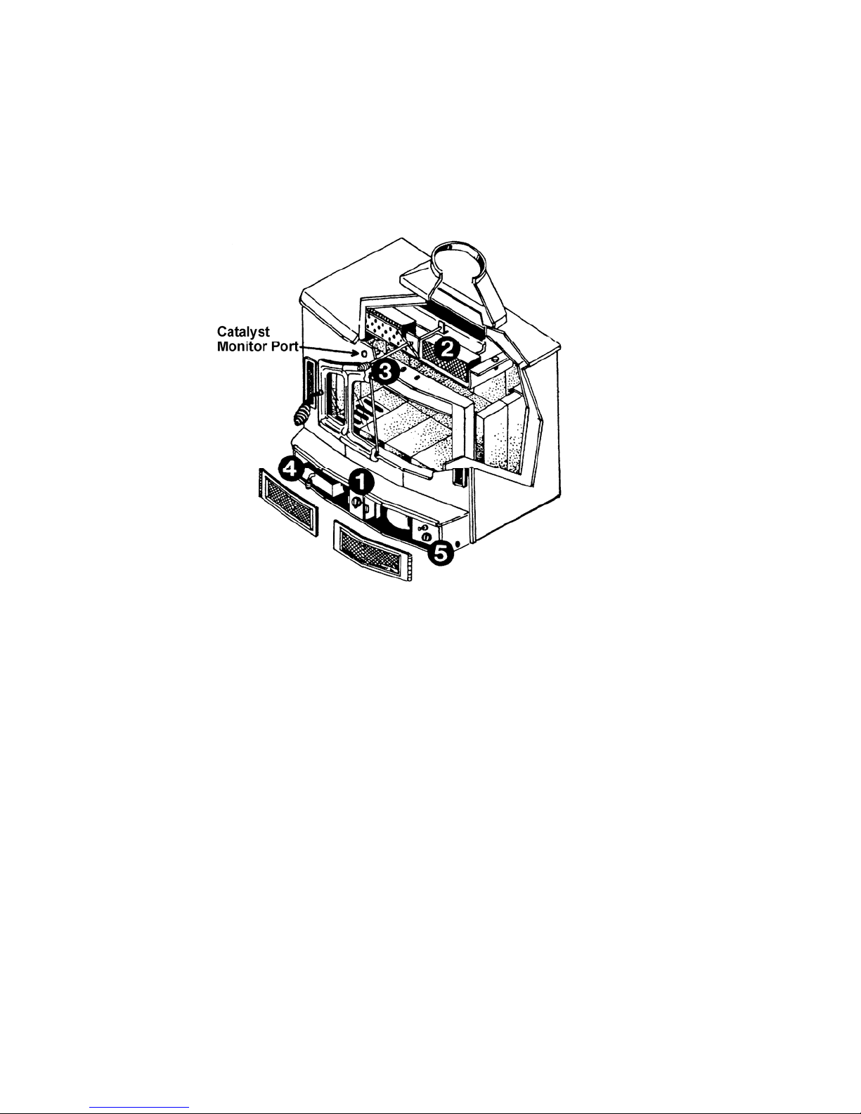
Familiarize yourself with the components of your stove before installation and operation. This owner’s
manual has been designed to assist you in installing, operating and maintaining your Energy King
stove efficiently and safely. Keep it in a safe place for future reference.
1. Manual Draft Control. Controls burn rate by regulating air entering the stove. It is located
beneath the loading door. Turn the control all the way to the right for maximum air intake, burn
rate and heat output, and all the way to the left for minimum air intake and heat output, with a low
burn rate.
2. Catalytic Combustors. The wood heaters contain catalytic combustors, which need periodic
inspection and replacement for proper operation. It is against the law to operate these stoves in a
manner inconsistent with operating instructions in this manual or if the catalytic element is
deactivated or removed. The catalytic combustors in these stoves are designed to burn the
smoke, carbon monoxide and particulate, which are not burned by the fire. Once the fire has
been established you can engage the catalytic combustors by shutting the bypass. (Minimum
catalytic light off will not occur until the stove reaches 500 degrees F.) (See the instructions on
page 21 for replacement of the catalytic combustors.)
3. Bypass. The bypass control is located above the loading door. The bypass control should be
pulled out all the way to allow smoke to bypass the catalytic combustor when first starting a fire
and until the unit reaches the 500-degree temperature necessary for light off. The catalytic
bypass should also be pulled out all the way when loading the stove with fuel.
4. Ash Pan. Designed for easy clean up of ash accumulation. Do not operate the stove with the
ash pan open, always keep it closed.
5. Blower. The blower is designed to provide additional heating value and forced air convection.
Three speeds allow easy adjustment.
2
Page 6
Installation Materials Needed for Your Safety
(Freestanding Stoves)
Chimney Connector. Also known as flue pipe or stovepipe, the chimney connector joins the stove to
the chimney. It should be 6 inch diameter, minimum 24 MSG black or 25 MSG blued steel.
Thimble. A manufactured or site-constructed device installed in combustible walls and ceilings
through which the chimney connector passes to the chimney. It is intended to keep walls from
igniting.
Chimney. You must use either an approved masonry chimney or a prefabricated 6-inch listed high
temperature (tested to 2100 degrees F.) residential and building type heating appliance chimney per
UL 103 or ULC S629. The chimney size should not be less than or more than three times greater
than the cross-sectional area of the flue collar. Components required by manufacturers for
installation such as the chimney support base, firestop (as appropriate), attic insulation shield,
insulated tee, etc., are necessary to assure a safe chimney installation. Use only components
manufactured for the chimney.
Floor Protector
Stove. Use a listed floor protector or any non-combustible material.
Insert. Use a listed floor protector or material having a thermo conductivity of K-O.84 BTU – inches
per foot square – hour – Fahrenheit degrees; or equivalent to 3/8” non-asbestos millboard.
Fireplace Insert Installation
Specifications – Model Bay 2000C
Height 23 ¾”
Width 33”
Depth 24”
Weight 460 lbs.
Maximum Log Size 21”
Minimum Fireplace Dimensions
Height 23 ¾”
Width 32”
Depth 16”
Surround Dimensions
Height 32” Width 45”
Heating Capacity
Low Burn Rate 11,400 BTU/Hr.
High Burn Rate 34,600 BTU/Hr.
Weighted Average Particulate Emissions Overall Efficiency 78.5%
2.5 grams per hour
(Unit was tested with blower, three-speed switch)
Efficiency calculated per CSA B415 Standard
3
Page 7

Clearances to Combustibles
Model Bay 2000C Fireplace Insert
A To Mantle 18”
B To Side Trim 9”
C To Top Trim 14”
D To Sidewall 16”
E Hearth Pad Extension to front 16”
F Hearth Pad Extension to Side 8”
Refer to NFPA 211 for clearance reduction methods.
4
Page 8
Venting System
Proper draft must be provided for your Energy King unit. Draft is the force that moves air from the
stove up through the chimney. The amount of draft in your chimney depends on the length of the
chimney, local geography, nearby obstructions, and other factors. Too little draft may cause
backpuffing into the room and plugging of the chimney or catalyst.
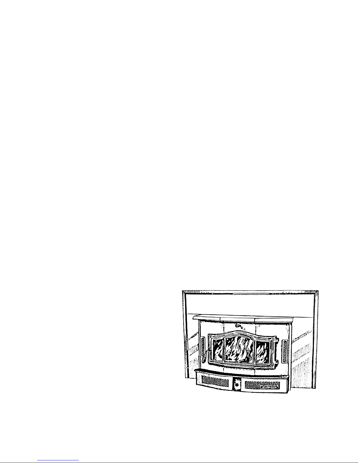
The Energy King fireplace insert model Bay 2000C is intended only for installation into a masonry fireplace
constructed in accordance with the requirements of the Standard for Chim neys, Fireplaces, Vents and Solid Fuel
Burning Appliances, NFPA No. 211, or applicable local code requirements. Please consult local building and
fire officials about fire restrictions and installation requirements. FOR USE WITH SOLID FUEL ONLY.
5
Page 9
Connection to a Masonry Fireplace
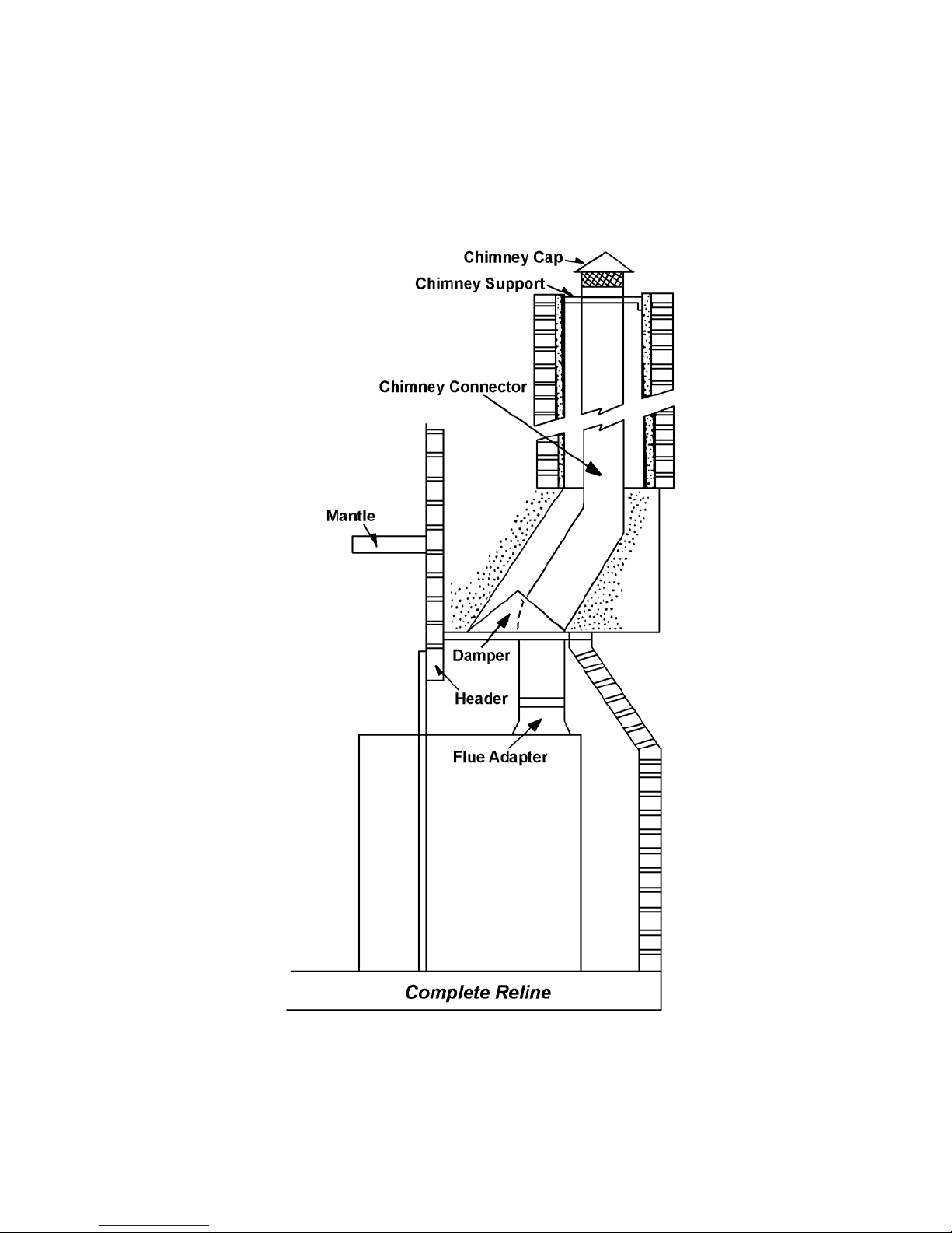
There are several kits available to connect the stove to a masonry fireplace. Look for a listed kit. The
kit is an adapter that is installed at the location of the fireplace damper. The existing damper may
have to be removed to allow installation of the kit. The key points of this type of stove connection are,
first, the connector pipe must extend up the chimney above where the fire clay liner starts. Secondly,
the areas of the kit installation and connector penetration should fit tightly and be sealed with high
temperature furnace cement unless the kit’s instructions state otherwise.
The tight fitting installation aids the proper draw of the chimney.
DO NOT REMOVE BRICKS OR MORTAR FROM MASONRY FIREPLACE. INSTALL AND USE
ONLY IN MASONRY FIREPLACE. USE A LISTED FLOOR PROTECTOR OR ANY NONCOMBUSTIBLE MATERIAL. FIREPLACE INSERT FLOOR PROTECTOR MUST EXTEND AT
LEAST 8 INCHES TO EACH SIDE OF UNIT AND 16 INCHES IN FRONT.
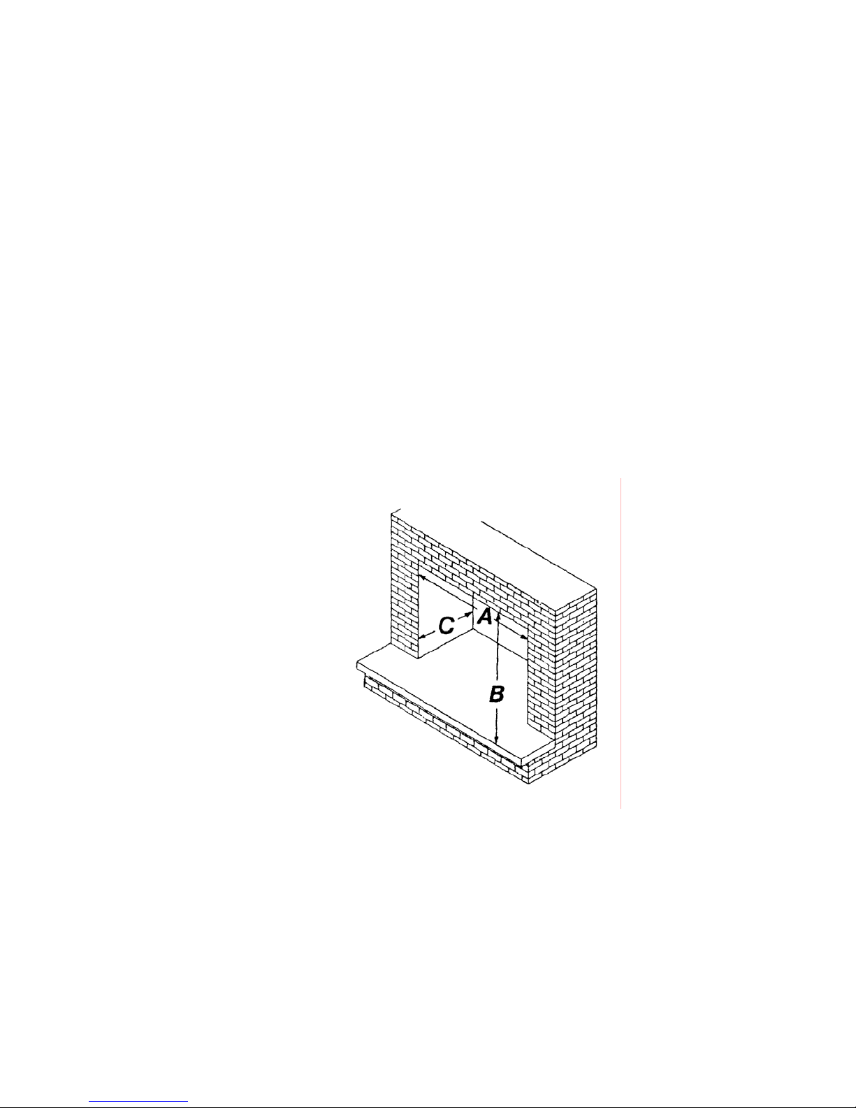
The Bay 2000C will insert into any masonry
fireplace that is at least (A) 32” wide, (B) 24” high,
and (C) 16” deep.
Before Installation
1. Check to make sure your masonry fireplace and chimney are in safe condition. Check the
chimney for cracks, loose mortar, and other signs of deterioration and blockage. The insert
should not be installed until it is determined that the chimney is safe for use. Since an oversized
flue contributes to the accumulation of creosote, the size of the flue should be checked to
determine that it is not too large for the insert.
The fireplace must be constructed to meet UBC Chapter 37 standards.
2. Clean the fireplace thoroughly.
3. Remove damper plate or block into open position with a non-combustible material.
4. Flue and chimney should be cleaned before installation.
6
Page 10

Mount Trim Panels
5. Measure from back of the unit to the front and mark on the sides the location of the support angle.
6. Place the angle on the side of the unit and mark the holes for the locking screws. Drill three 3/16”
holes and bolt in place on both sides of the unit.
7. Bolt side trim panels to the support angle with screws and tinnerman nuts.
8. Mount top panel to side panel.
Brass Trim
9. Place side brass pieces on the side of the trim panels and cut to length.
10. Place top brass piece on top trim panel and cut to length.
11. Place brass corner piece over the side and top pieces. Mark and drill two 3/16” holes through
brass.
12. Drill one 3/16” hole near the bottom of each side brass piece.
13. Using six brass bolts and nuts, bolt brass trim to trim panels.
14. Place insulation around trip panels. Slide insert into masonry fireplace. Be sure to center and
level unit in place. Push tight against fireplace front. Make sure unit is in far enough to allow
proper chimney hookup, and smoke outlet is behind fireplace lintel to assure safe operation. If
brick is rough, additional insulation may be needed. Use only HIGH HEAT insulation approved for
woodburning stoves and inserts.
Direct Connect
The 8” obround connection (cast iron) must be bolted securely to the fireplace and fastened to the
chimney liner. A 6” offset direct connection must be used when the installation utilizes a 6” flexible
stainless liner.
7
Page 11

Freestanding Stove Installation
Specifications – Model Bay 2000C
Height 35”
Width 33”
Depth 24”
Weight 510 lbs.
Maximum Log Size 21”
Heating Capacity
Low Burn Rate 11,400 BTU/Hr.
High Burn Rate 34.600 BTU/Hr.
Efficiency
Weighted Average Particulate Emissions
2.5 grams per hour
Overall Efficiency 78.5%
Efficiency calculated per C.S.A. B 415 Standard
The Bay 2000C Freestanding Stove must be connected
to a listed high temperature (2100 degrees F) residential
type and building heating appliance chimney per US 103
or ULC S629 or an approved masonry chimney with a
flue liner.
(Unit was tested with blower, three-speed switch.)
8
Page 12
Base Assembly
To assemble as a stove, you need to bolt the base to the bottom of the unit using five ¼”
self-tapping screws.
Remove door, brick and grate. Set unit on its back to mount the base. Place base with slotted holes
towards the unit and line up with punched holes on the bottom of the unit. Use the five ¼” self-tapping
bolts to mount securely.
Flue Adaptor
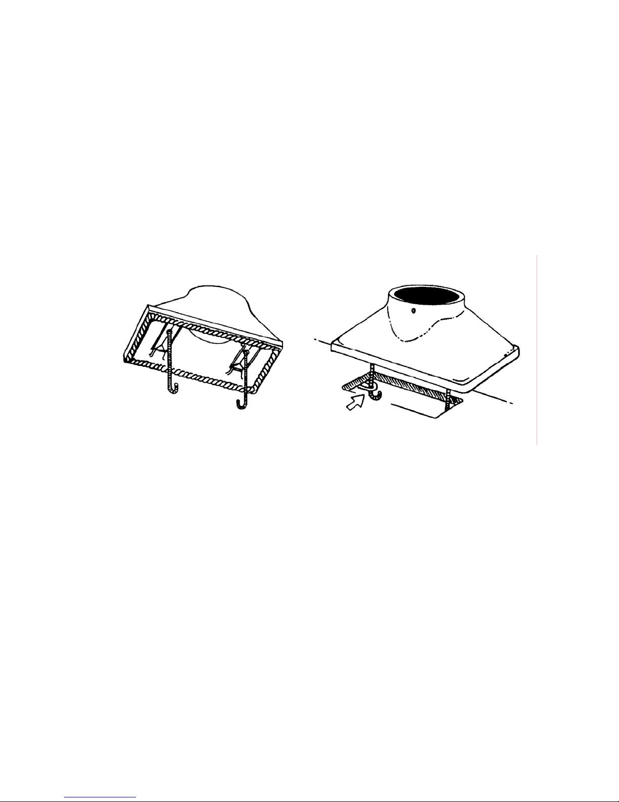
The flue adaptor must be secured atop the unit for freestanding stove installation.
To attach the adaptor:
1. Attach the flat gasket to the adapter.
2. Set the flue adapter onto the top of the flue opening.
3. Center the adapter evenly over the flue.
4. Locate the two J shaped threaded screws. Remove the nut and washer from each. Set them
aside.
5. Lower the J shaped screws into the flue adapter opening, and insert each through the holes in the
adapter and stove.
6. Reaching inside the flue adapter, replace the nut and washer on each J shaped screw.
7. Tighten securely, using a wrench.
9
Page 13
Clearances to Combustibles
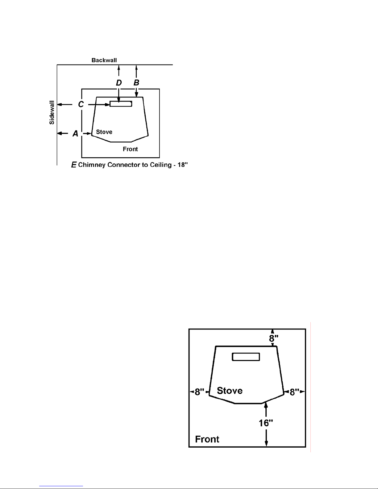
Model Bay 2000C Freestanding Stove
A Unit to Sidewall 16”
B Unit to Backwall 18”
C Chimney Connector to Sidewall 29”
D Chimney Connector to Backwall 18”
E Chimney Connector to Ceiling 18”
When locating your stove, consider safety, convenience, traffic flow, and the fact that the stove will
need a chimney and chimney connector.
Your stove should be located away from doors and hallways and in an open area to allow for
necessary clearances.
Keep furniture, drapes, curtains, wood, paper, and other combustibles far away from the stove.
Never install the stove in locations where gasoline, kerosene, charcoal lighter, or any other flammable
liquids are used or store.
DO NOT INSTALL THIS STOVE IN A MOBILE HOME.
A variety of prefabricated clearance reductions systems may be available through your stove dealer.
Always look for a safety listing label on the product when selecting a prefabricated clearance
reduction system and make sure it is designed for use with a woodstove. Follow exactly the
installation instructions provided with this system. Refer to NFPA 211 for clearance reduction
methods.
Floor Protector
The stove must be placed on a floor
protector if the floor is wood or other
combustible flooring. IF
CARPETING IS PRESENT, IT
MUST BE REMOVED. THE FLOOR
PROTECTOR MUST NOT BE
PLACED ON CARPET. The floor
protector must extend at least 8
inches from the sides and back of
the stove, and 16 inches from the
door of the stove. Insulate this area
with 3/8” millboard or equivalent (R
Factor = .75) The overall base size
is 50” x 50” minimum.
10
Page 14
Venting System
A chimney connector and chimney make up the venting system. Inside, chimney temperatures may
exceed 2000 degrees F. To protect against a chimney fire, the connector and chimney must be
properly installed and maintained. When a connection is made through a combustible wall to the
chimney, a thimble must be used. A chimney support package must be used when a connection is
made through the ceiling to a prefabricated chimney. These accessories are of primary importance to
provide safe clearances to combustible wall and ceiling materials.
The unit may be connected to either a code approved masonry chimney with a flue liner or a
prefabricated listed high temperature (tested to 2100 degrees F) residential and building type heating
appliance chimney per UL 103 or ULC S629. The chimney size should not be less than or more than
three times greater than the cross-sectional area of the flue collar. Do not connect it to a chimney
serving another appliance.
Proper draft must be provided for your Energy King unit. Draft is the force that moves air from the
stove up through the chimney. The amount of draft in your chimney depends on the length of the
chimney, local geography, nearby obstructions, and other factors. Too much draft may cause
excessive temperatures in the stove and may damage the catalytic combustor. Inadequate draft may
cause backpuffing into the room and plugging of the chimney or catalyst.
Chimney Connector
Your chimney connector should be 6-inch diameter, minimum 24
MSG black or 25 MSG blued steel. Aluminum and galvanized steel
should not be used, since they cannot withstand the high temperatures
a wood fire produces. Never use chimney connector pipe as a chimney.
You must connect your stove to a chimney like those illustrated in this
manual. DO NOT PASS CHIMNEY CONNECTOR THROUGH
COMBUSTIBLE WALL OR CEILING.
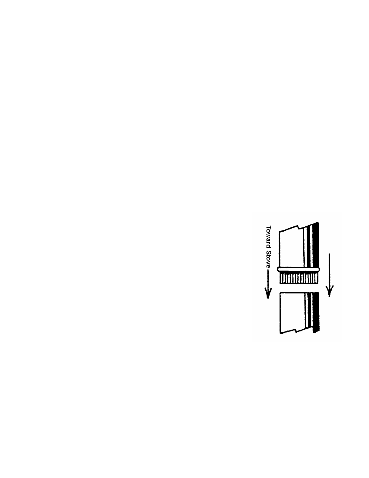
Chimney connector sections must be attached to the stove and to each
other with the crimped end toward the stove. This allows creosote to run
into the stove and not onto the outside of the pipe. All joints, including
transition to chimney connector, should be secured with three sheet
metal screws. Otherwise, in the event of a creosote fire, the connector
may vibrate apart.
For proper operation, the chimney connector should be as short as
possible. Horizontal lengths of chimney connector should have an
upward slope from the stove of ¼ inch per foot.
Maintain 18 inches clearance between the chimney conne ctor an d the
wall and ceiling unless a wall protection system is installed.
When installing the stove into a masonry chimney, be sure to check for
signs of deterioration and blockage. Once the chimney is determined to
be safe, installation can proceed. The size of the flue should also be
checked. The chimney must have a fire clay liner or stainless steel lining
must be installed. The stainless steel lining should be single wall pipe, 6
inches in diameter, a minimum 24 gauge. If a flue lining is used, an air
space between the flue liner and the chimney wall of ½ inch must be
maintained.
A list of the more important minimum requirements for a properly
constructed chimney follows.
11
Page 15
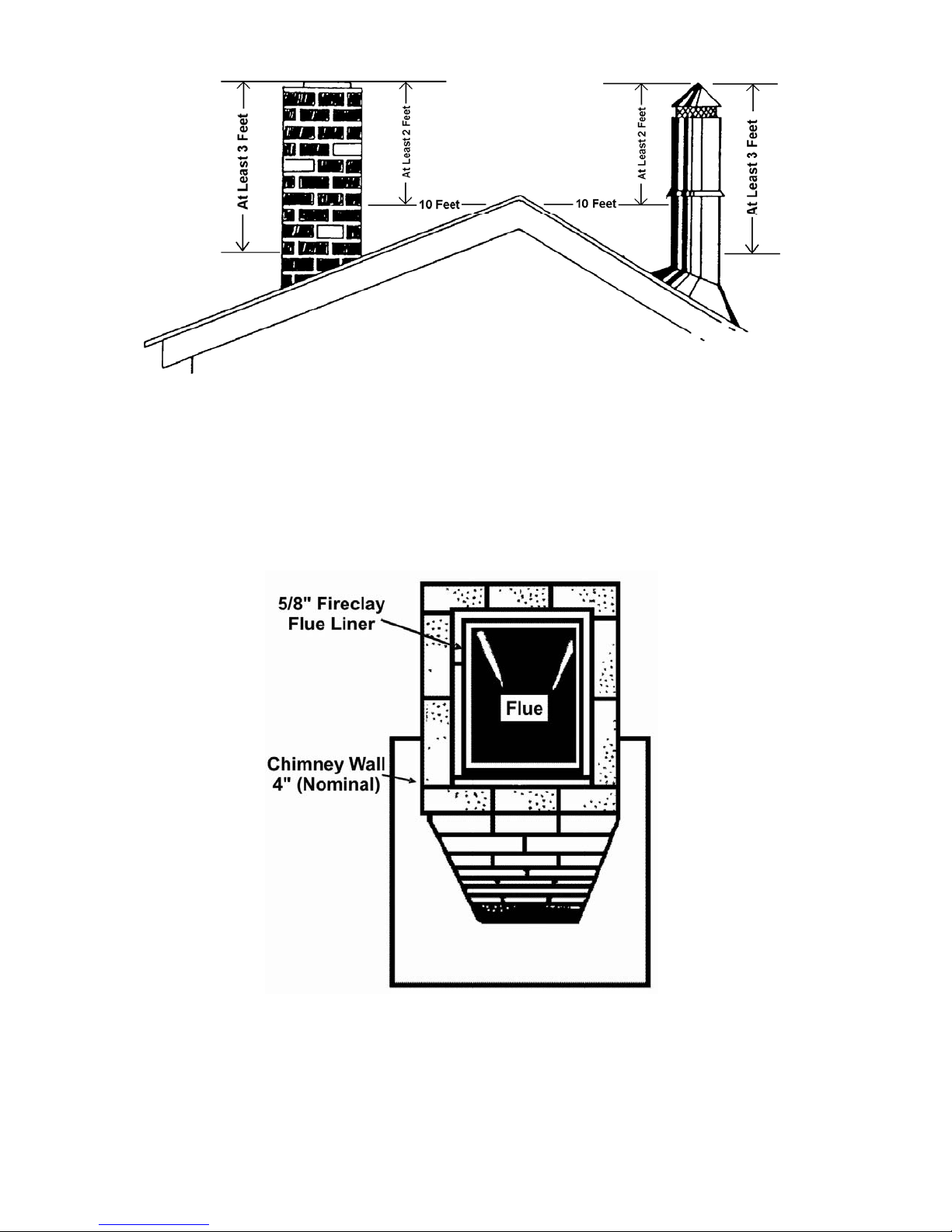
1. For proper operation and safety, the chimney must be at least 3 feet higher than the highest point
where it passes through the roof, and at least 2 feet higher than the highest part of the roof or
structure that is within 10 feet of the chimney, measured horizontally.
2. Class A chimneys on the outside of the house must have a minimum of one inch clearance to the
combustible structure, while a chimney inside the house and through the ceiling must have at
least two inches of clearance to the combustible structures. At all points where the chimney
passes through floors and/or ceiling, fire stops must be installed. An air space between the
chimney and insulation of 2 inches or more must be maintained.
3. The wall of the Class A chimney, if constructed of brick or modular block, must measure a
minimum of 4 inches nominal thickness. Mountain or rubble stone wall must be at least 12 inches
thick.
4. Installation of single wall pipe from the heater to the masonry flue should rise ½ inch per every
one foot of pipe distance from the heater to the chimney.
12
Page 16
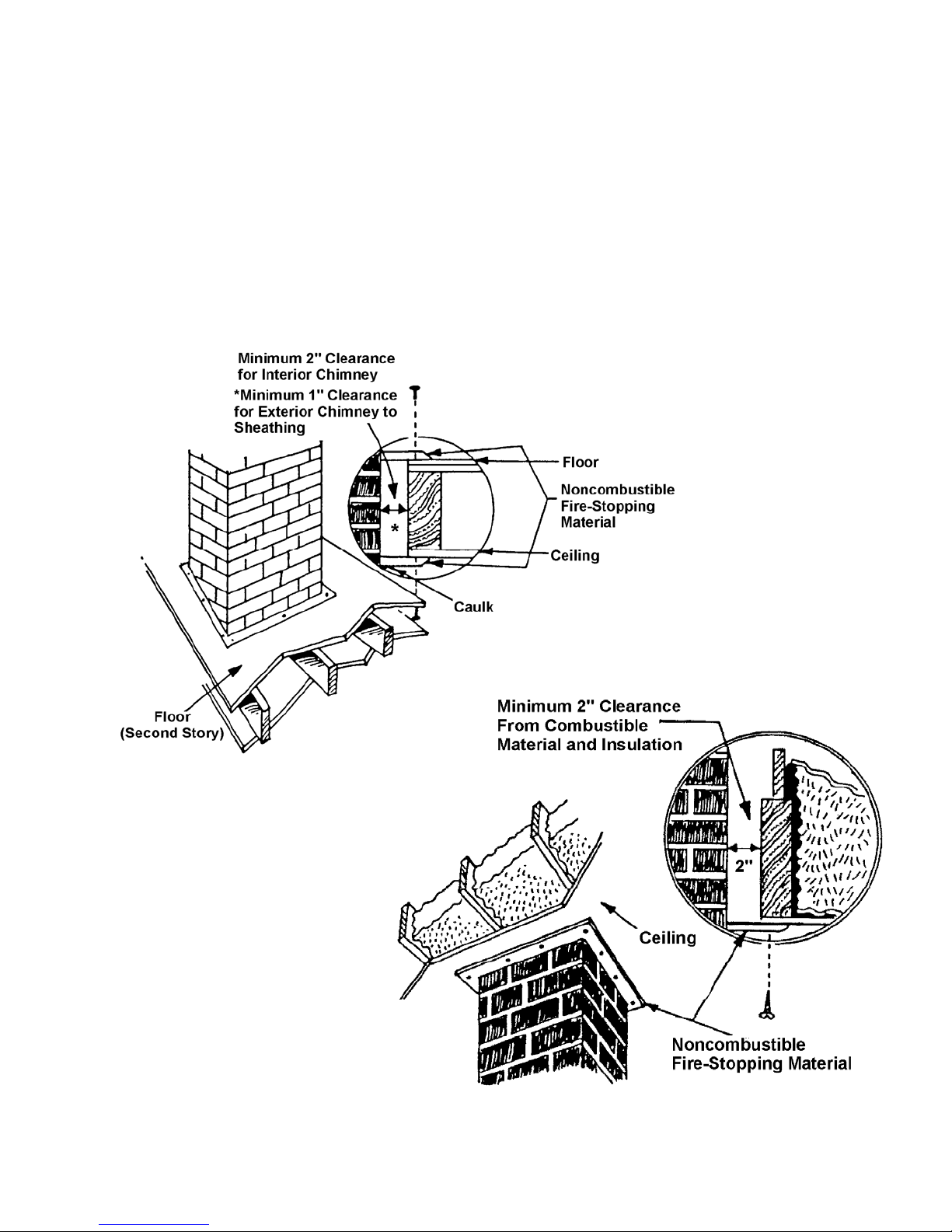
Firestopping
Remember that insulation must not contact the chimney. There must be air space around the
chimney.
Insulation must be 2 inches or more from the chimney.
DO NOT PASS CHIMNEY CONNECTOR THROUGH COMBUSTIBLE WALL OR CEILING. SEE
LOCAL BUILDING CODE AND MANUFACTURER’S INSTRUCTIONS FOR PRECAUTIONS
REQUIRED FOR PASSING THROUGH COMBUSTIBLE WALL OR CEILINGS .
13
Page 17
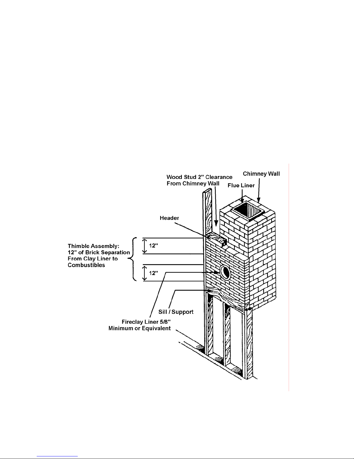
Thimble
When installation entails connection from
the stove through a combustible wall to a
masonry chimney, a thimble must be used.
Two of several methods of connection
through a combustible wall are illustrated
below. For alternatives, consult your local
building authority or NFPA 211.
Listed prefabricated metal thimbles can be
bought for use with woodstoves. The
manufacturer’s installation for the thimbles
must be strictly followed. Maintain all
designated clearance to combustible
materials.
14
Page 18
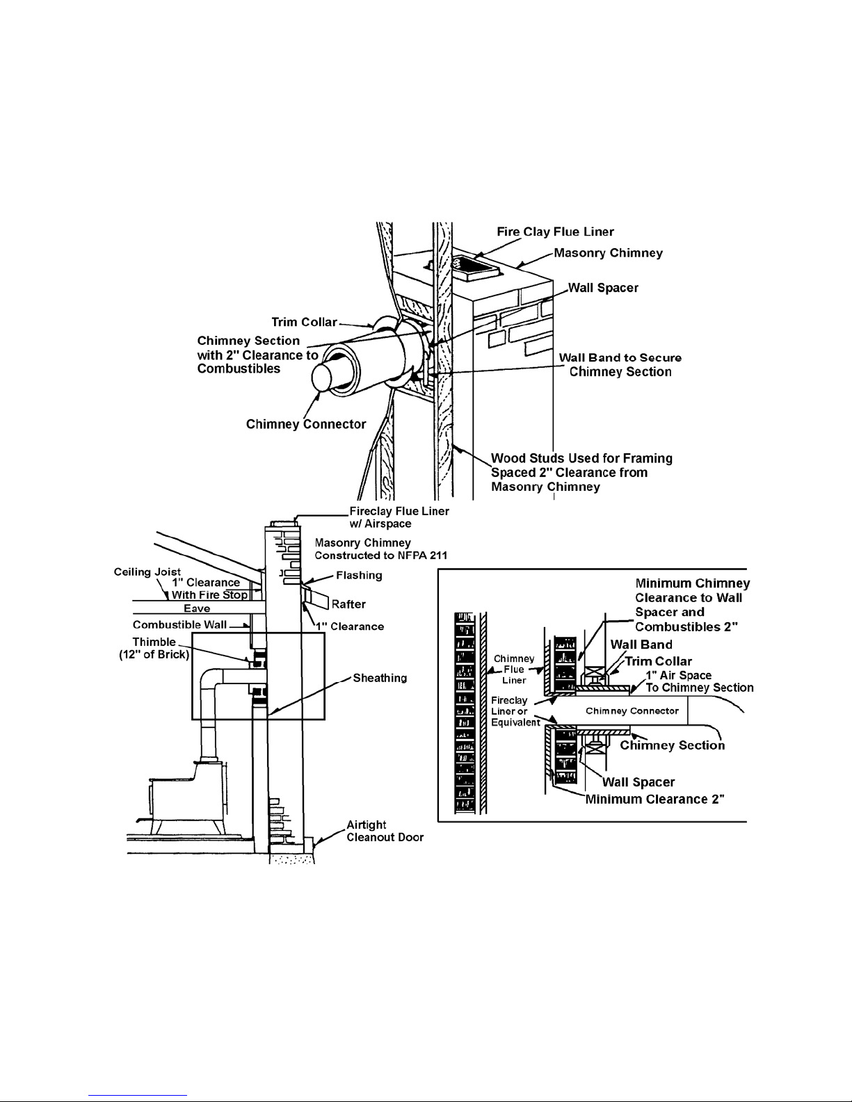
Brick Chimney Thimble Assembly
Construction of the brick thimble assembly requires 12 inches of brick around a fire clay liner. Be sure
the point of penetration allows an 18” clearance from the connector to the ceiling. An opening of 32
inches (for a 6-inch chimney connector) must be cut in the wall to maintain the required 12 inches of
brick separation from combustibles. It will be necessary to cut wall studs and install a header and sill
frame to maintain proper dimensions and to hold the weight of the brick.
Minimum 3 ½” (4 inch nominal) thick solid bricks are to be used. The fire clay liner (ASTM C35 or
equivalent), minimum 5/8 inch wall thickness, must not penetrate into the chimney beyond the inner
surface of the chimney flue liner and must be firmly cemented in place. If it is necessary to cut a hole
in the chimney liner, use extreme care to keep it from shattering. Refractory mortar must be used at
the junction to the chimney liner. After the assembly is complete, insert the chimney connector in the
fire clay liner. Do not push it beyond the inside edge of the chimney liner because this will affect the
draw of the chimney.
15
Page 19
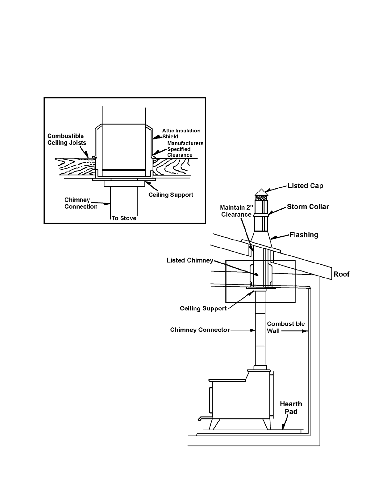
Install an attic insulation shield to maintain the specified clearance to insulation. Insulation in this air
space will cause a heat buildup that may ignite the ceiling joists.
This method of installation requires at a minimum a ceiling support package, an insulation shield and
roof flashing.
16
Page 20
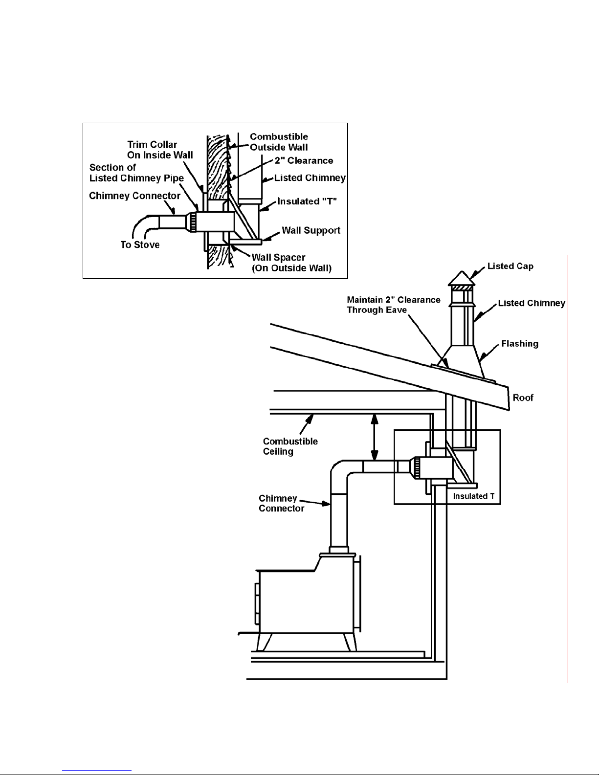
This method of installation requires at a minimum a wall pass through device, a wall support package
and insulated “T” section and roof flashing
17
Page 21

Warnings
This heater is designed to burn natural wood only. Higher efficiencies an
when burning air dried, seasoned hardwood, as compared to softwood or green or fre shly cut hardwoods.
d lower emissions generally result
DO NOT BURN
Treated wood
Colored paper
Garbage
Cardboard
Solvents
Coal
Trash
Burning treated wood, garbage, solvents, colored paper or trash may result in release of toxic fumes and may
poison or
Burning coal, cardboard, or loose paper can produce soot, or la
combustor, causing smoke spillage into the room, and rendering the combustor ineffective.
render ineffe
ctive the catalytic combustor.
rge flake
s of char or fly ash that can coat the
Backpuffing – Smoke from closed fuel door
If smoke enters the room when the fireplace door is closed, check for the following causes:
Proper draft has not had time to establish. Open draft control.
Blockage in the fireplace, stovepipe or chimney.
Leaks in the chimney.
Cold outside chimney.
Chimney is too short.
Chimney is too close to trees or a nearby high roof.
Overfire
Never operate the unit with fuel door or ash pan open.
Do not overfire. Using flammable liquids, too much wood, or burning trash in the fireplace, may result in
overfiring. If the chimney connector or fireplace glows red or even worse, white, the stove is overfired. This
condition may ignite creosote in the chimney, possibly causing a house fire.
If you overfire, immediately close the fireplace damper and doors to redu
Department immediately. DO NOT OPERATE THE STOVE AGAIN UNTIL IT IS DETERMINED THAT THE
CHIMNEY AND ITS LINING HAVE NOT BEEN DAMAGED AND ARE SAFE.
ce the air supp
ly to the fire. Call the Fire
18
Page 22

Operating Your Energy King
What is a Catalytic Woodstove?
A catalytic combustor is an element which, when used properly in a woodbu
carbon monoxide and particulate which are not burned by the fire. Think of it as an “after burner” which,
because of a “catalyst,” chemically breaks down smoke, carbon monoxide and particulate into substance s that
are burned at a low temperature.
rning appliance, will “burn” smoke,
Using Your Catalytic Woodstove
The most important thing to remember when operating a catalytic combustor eq
make sure you have achieved catalytic light off before you place the unit into the catalytic operational mode.
Light off simply means that you have achieved enough temperature within your unit to start the catalytic
combustor operating.
Catalytic burning, like all types of burning, requires three e
“smoke” is the fuel. The temperature needed to begin catalytic activity is generally 500 to 700 degrees F. This
is a temperature that is easily achieved when you build a fresh fire or when you reload your existing fire.
The use of a magnetic thermometer, a probe thermometer, or vari
today will be of help to you in determining if you have achieved the necessary temperature. The monitor port for
the temperature monitor equipment is located 2” to the left of the bypass pull rod.
Your Energy King stove is equipped with a bypass mech
to “bypass” the smoke around the combustor when you do not have the necessary 500 degrees to start
catalytic activity or when you are reloading your stove. To aid in catalytic light off, coals should be moved aside
at the front of the door opening and a tunnel made under the fuel.
The other important thing to remember when operating a catalytic
burning device) is to burn seasoned, dry wood only and not to use your wood burning stove or insert as a
“garbage incinerator.” A “catalyst” is an element that causes something to happen under conditions by which
they would not normally happen, without being consumed or used up by the reaction. In a wood burning
appliance, this simply means that the catalyst is allowing the smoke to be burned at 500 to 700 degrees F.
rather than the normal 1,100 to 1,200 degrees F. that it would take to burn all elements.
There are elements in garbage, other than dried, seasoned wood t
these elements are lead, sulfur, etc., and as they come in contact with the catalyst, they stick to it, covering it
up, so that the elements in wood smoke such as hydrocarbons, particulate and carbon monoxide ca nnot
contact the catalyst and are not burned. This process is referred to as “poisoning”, and after a period, the
catalyst is covered and your catalytic combustor will no longer work. How long this proce s s will take to
completely cover all the catalyst depends on what you burn in our stove.
ssential
anism, located above th
elements: fuel, oxygen and temperature. The
ous digital re
combusto
hat the catalyst will not rea
uipped stove or insert is to
adouts available on the market
e door. The bypass allows you
r equipped device (or any wood
ct with. Some of
19
Page 23

Troubleshooting Your Catalytic Combustor
Problem: Creosote accumulation or dirty smoke from the chimney
Possible causes Solution(s)
You are not getting light off in the combustor Make sure you have achieved 500 degrees F.
(necessary for light off) before engaging the
combustor.
You are burning wet wood or improper fuels. Burn only dry, seasoned wood.
Your bypass mechanism is not fully closing, When the stove is not burning, make sure that
allowing the smoke to go around the combustor the bypass mechanism is closing fully and that
rather than through the combustor. there are no obstructions
Replace your catalytic combustor.
Problem: Plugged combustor
Possible causes Solution(s)
You did not achieve light off temperature prior Make sure you have at least 500 degrees F.
to closing your bypass mechanism and necessary for light off) before you engage the
engaging your combustor. combustor.
You are burning materials that are coating Burn only dry, seasoned wood. Lightly brush the
the catalyst, such as heavy papers, wet face of the combustor with a soft bristle brush,
wood, garbage, etc. such as a paintbrush, to remove the accumulation.
Then build a hot fire in your stove, engage the
combustor half way, then two-thirds, then fully to burn
the accumulation off the combustor.
Your catalytic combustor is no longer Replace your catalytic combustor.
functioning and needs to be replaced.
How do I know my catalytic combustor is working?
Ask yourself the following questions. If your answers are yes, your catalytic combustor is working properly.
1. Am I burning less wood to get the same amount of heat?
2. Does my combustor glow red for a short amount of the time (approximately 1-1/2 hours) during my wood
load?
3. Is there substantially less creosote in my chimney?
4. Is the smoke exiting my chimney white in color and usually odorless?
5. Does a visual inspection of the combustor show it to be clean of any fly ash, creosote or soot?
If the answer to any of the above questions is no, the solutions outlined previously may help you to activate
your combustor again
20
Page 24
Replacing Your Catalytic Combustor
Visually inspect the catalytic combustor at least three times during the heating season to determine if
physical deterioration has occurred. Only replace the combustor if it is damaged or no longer
operating and use only Applied Ceramics Combustors. (See Applied Ceramics Warranty for
information on replacement)
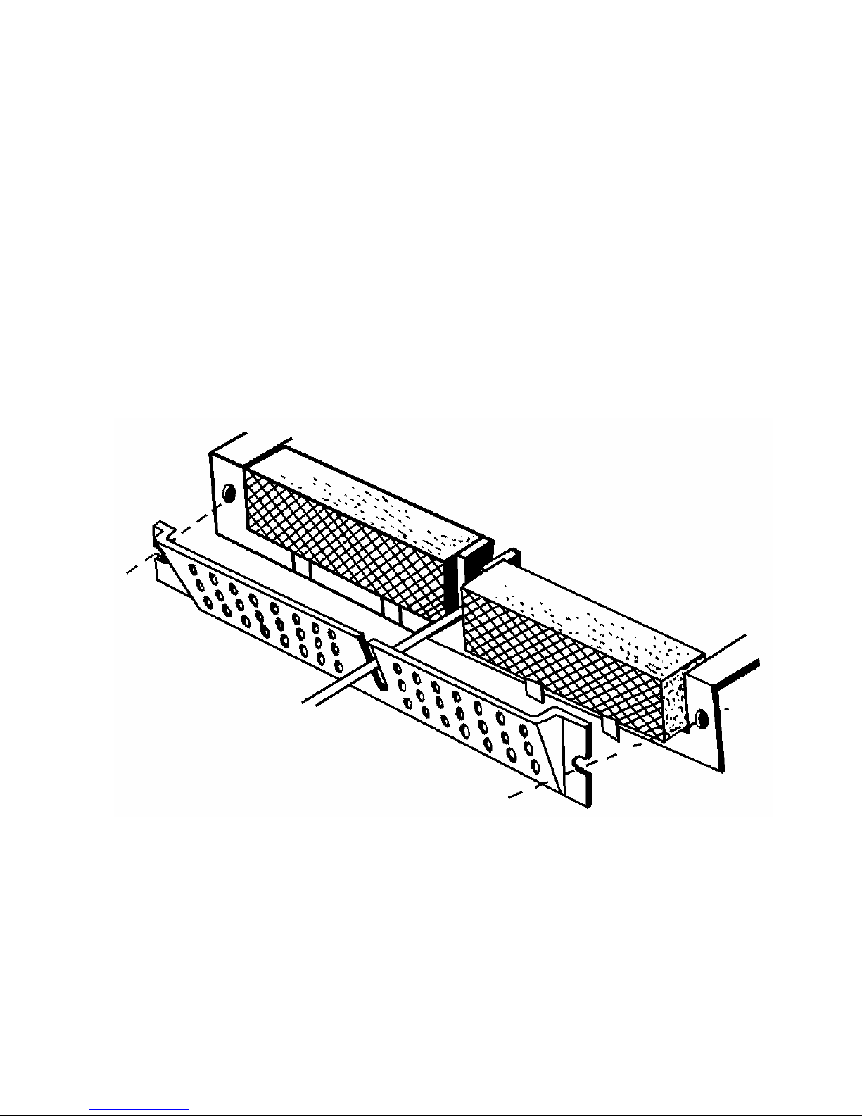
The Energy King fireplace has two catalytic combustors. To replace combustors, look up inside the
stove and locate the catalytic combustor retainer plate with holes across its surface. Remove the
bolts on each side of the plate and remove the plate. Next, remove the catalytic combustor. Position
the replacement catalytic combustors snugly and replace the retainer plate, tightly bolting the plate on
both sides.
21
Page 25
Burning Your Energy King Stove
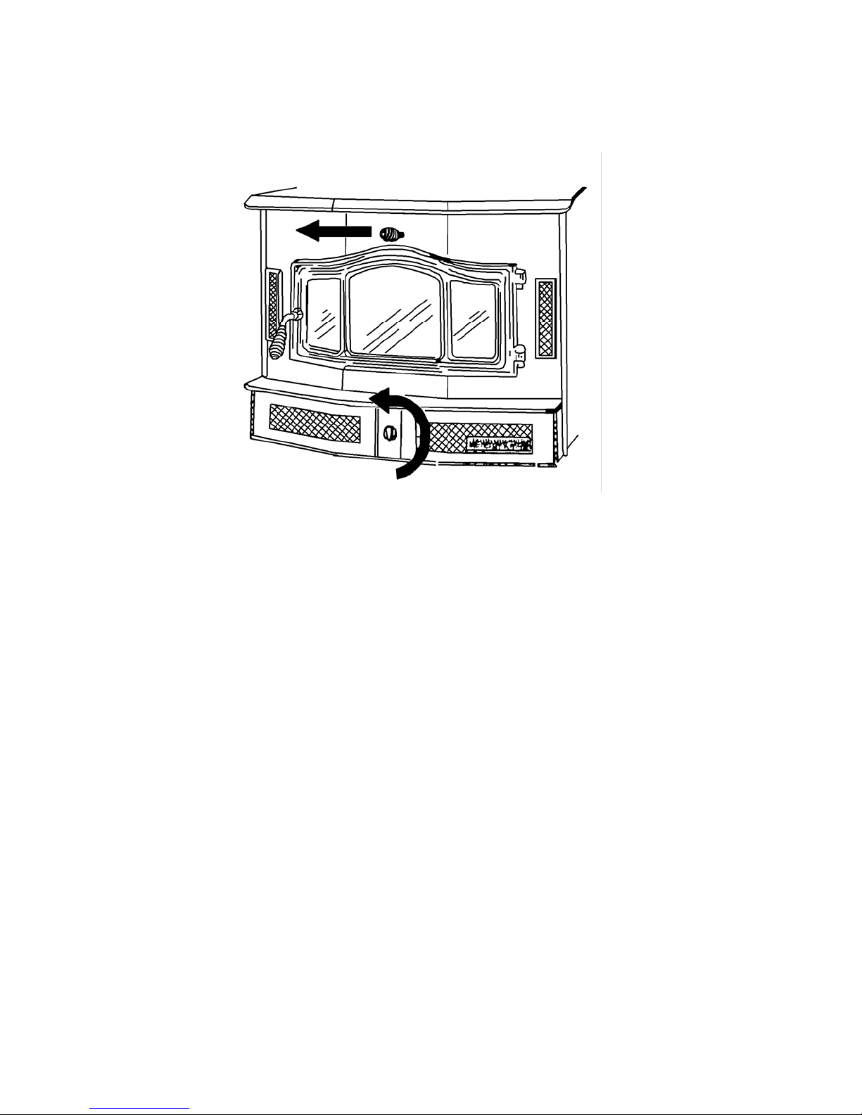
1. Before building a fire, open the bypass, located above the door, to the open position by pulling it
all the way out.
2. Open the air control, located above the door, by turning it all the way to the left.
3. Start your fire with paper and kindling on the firebrick refractory hearth. Do not elevate the fire
with grates or andirons.
4. Once the fire establishes coals, move the coals aside at the front of the door opening and form a
tunnel under the fuel. This will help light off to occur.
5. Add wood to the fire.
6. Continue to burn your fire with the air control fully open for 20 to 45 minutes. This insures that the
stove, catalyst, and fuel are all stabilized to proper operating temperature. Even though it is
possible to have gas temperatures reach 600 degrees F. within two or three minutes after a fire is
started, if the fire is allowed to die down immediately, it may go out or the combustor may stop
working. Once the combustor starts working, heat generated in it by burning the smoke will keep
it working.
7. After 45 minutes, close the bypass.
8. Close the air control half way for maximum fuel efficiency and burn time.
9. When fueling your Energy King, open the bypass and air control all the way and wait a short time
before opening the door. This will eliminate the risk of flame and smoke spillage.
10. Once the stove is fueled, reset the bypass to the closed position, and the air control to medium.
11. During the refueling and rekindling of a cool fire, or a fire that has burned down to the charcoal
phase, operate the stove at a medium to high fire rate for about ten minutes to insure that the
catalyst reached approximately 600 degrees F.
22
Page 26
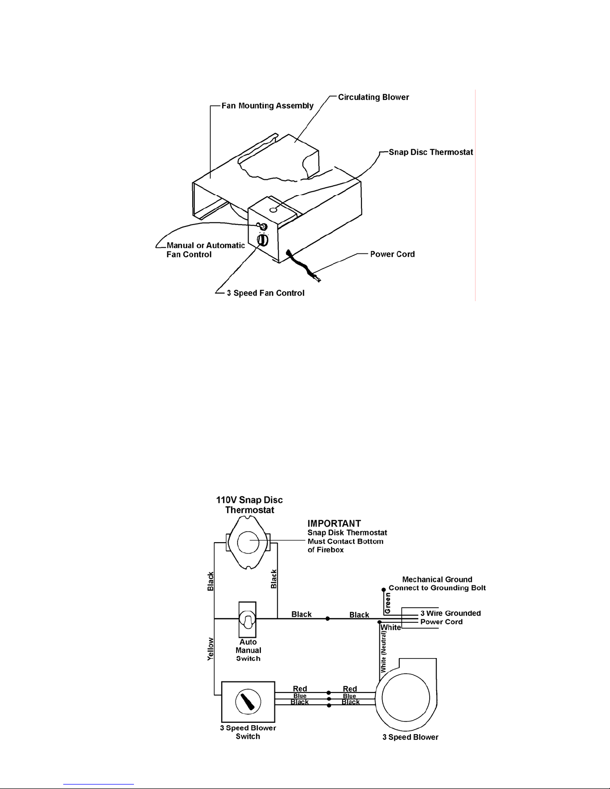
Operating the Circulating Blower
Blower Motor Rating: 115VAC/1.8 AMPS / 60HZ
Location: Behind cover door on right side of unit front.
WARNING: ROUTE POWER SUPPLY CORD AWAY FROM UNIT. NEVER COVER AIR INLETS
ON THE TWO COVER DOORS – Unit front.
The circulating blower operates on 110V., must be plugged into a three prong grounded plug. The
blower is controlled by operating a 3-speed switch (high, medium, low). Switch location – bottom of
the switch housing inside right cover door.
The fan is operated automatically by a thermostat located on the top of the switch housing. When
operating temperature is achieved, the thermostat will automatically turn on the fan to circulate hot air
form the air chamber. A toggle switch located on the upper half of the mounting plate will bypass the
thermostat and run the fan continuously.
DANGER: RISK OF ELECTRIAL SHOCK – DISCONNECT POWER BEFORE SERVICING UNIT.
Wire Diagram
23
Page 27
Wood
Choosing the kind of firewood to burn in your stove depends on what is available to you. If all you can
obtain is softwoods, obviously, that will be your choice.
Softwoods, such as pine and fir, are easily ignited and burn rapidly with hot flames. However, since
they burn so easily and quickly, you will have to spend more time loading your stove, especially in the
high burn rate. With softwoods, it will be much more difficult to achieve an overnight burn.
It is best to use more dense hardwoods for a longer lasting fire. It is also a good idea once the fire is
established to use larger diameter wood stacked tightly together. This will promote a longer bu rn time.
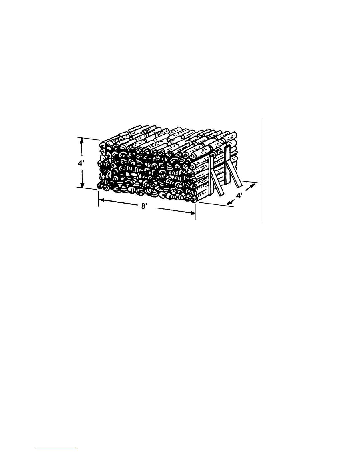
So that you have an idea of how firewood is sold, you should first know that the most common
measurement is the standard “Cord.” A cord is a nicely stacked pile of wood that measures, 4’ x 4’ x
8’. ALWAYS look for the driest wood especially if you must purchase wood by weight. Unseasoned,
wet wood is much heavier.
If your are going to cut your own wood, plan on drying your wood at least 6 months to 1 year. Stack
the wood in such a way as to allow air to circulate through the wood. Wood should be stored in a well
sheltered, ventilated area to allow proper drying during the year to come.
Maintaining Your Energy King
At the end of each heating season, clean the chimney. Vacuum out any ash accumulation. Replace
any worn gaskets or broken firebrick.
Disposal of Ashes
The ash pan is located in the left bottom access door. To remove ash pan, turn locking lever to the
left and pull out. Ashes should be removed year round and stored in a fireproof metal container with a
tight fitting lid. The container should be kept on a non-combustible floor or on the ground, well away
from all combustible materials, until all cinders have thoroughly cooled. If the ashes are disposed of
by burial in soil or otherwise locally dispersed, they should be retained in the closed container until all
cinders are thoroughly cool. An accumulation of too much ash restricts airflow an d reduces the
available burning area. A ½” to 1” layer of ash should be maintained, however, to support combustion
and insulate the bottom of the firebox. Be sure to lock ash pan in place by turning locking lever to the
right.
24
Page 28

Creosote – Formation and Need for Removal
When wood is burned slowly, it produces tar and other organi
moisture to form creosote. The creosote vapors condense in the relatively cool chimney flue of a
newly started fire or from a slow burning fire. Therefore, creosote residue accumulates on the flue
lining. When ignited, this creosote makes an extremely hot fire that may damage the chimney or even
destroy the house.
The chimney connector and chimney should be inspected at lea
season to determine if a creosote buildup has occurred. If creosote has accumulated, it should be
removed to reduce the risk of a chimney fire.
Inspect the system at the stove connection and at the chimney top. Cooler surfaces tend to build
reosote depos
c
bottom.
Creosote should be removed with a brush specificall
chimney sweep can perform this service. It is also recommended that before each heating season,
the entire system be professionally inspected, and cleaned and repaired if necessary.
its quicker, so it is important to check the chimney from the top as well as from the
y design
c vapors, which combine with expelled
st twice monthly durin
ed for the type of chimney in use. A
g the heating
Care of Glass
Your Energy King is equipped with a super heat resistant glass, available through your Energy
retailer. The glass can only be broken by impact or misuse. Never slam the door or impact the glass.
When loading fuel, be sure logs don’t touch the glass.
In case of breakage, glass must be replaced with a hig
Tempe
not operate the unit with cracked or broken glass. Replacement glass should be purchased from your
Energy King retailer or RJM Manufacturing, Inc. To remove the broken or damaged glass panel,
remove the glass retaining clips and carefully remove the glass panel. Insert the replacement glass
and attach the glass retaining clips.
The glass should be cleaned with a non-abrasive glass cleaner. Abrasive cleaners may scratch and
cau
red or ordinary glass will not withstand the high temperatures of the Energy King fireplace. Do
se the gl
ass to crack. Do not clean the glass when it is hot.
h temperature glass such as Robax.
King
Care of Gold Plated Door
A household glass cleaner and a soft cloth should be used to clea
clean the door when it is hot.
n the gold-plated door. Do not
Care of Blower
CAUTION: MOVING PARTS MAY CAUSE INJURY. DO NOT OPERATE UNIT WITH COVER
PLATE REMOVED.
se p
The blow
remove the clamping bolt located under the blower assembly, and pull out approximately 4”. Remove
the wire nuts that connect the power cord. (Black, white and green wire. ) Cle an the motor and blower
wheel by vacuuming away any dust or dirt. Place unit back into the opening, connect wires (black-toblack, white-to-white, green-to-mechanical ground.) Place unit in the rest of the way to the back fan
stop. Check to be sure wires are not cut or connections have not become loose. Place clamp bar over
bolt and tighten down. Connect power cord. Unit should now be ready to operate.
er assembly can be easily removed by following the
25
rocedures: Disconnect power,
Page 29
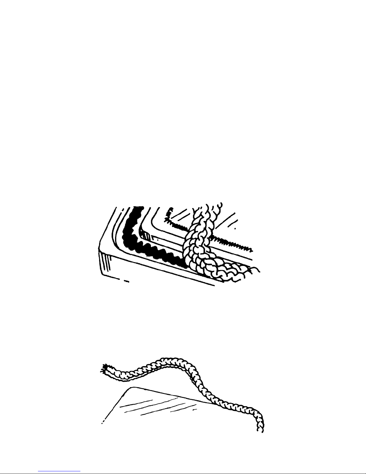
Gasket Replacement
Door and glass gaskets need to be replaced on an annual ba sis to insure that the stove remains
airtight. Failure of the door or glass gaskets will allow additional air to enter the stove and drastically
decrease the burn time of your fuel.
To check for gasket failure, start a fire in the stove. Once you have a well established fire, damper the
stove down. Next take a lit match and direct it along the edge of the door and stove. Do the same
along the inside edge of the door and glass. If you notice the flame from the match being drawn to the
gap, there is an air leak in the gasket and it needs to be replaced.
Door Gasket. To replace the door gasket, simply remove the door and lay it face down on a clean
soft surface, such as a towel. Find the ends of the gasket and pull it off. Take a screwdriver and
remove excess gasket glue from the channel. Take new stove gasket cement (available at your local
woodstove retailer or hardware store) and lay a medium to heavy bead around the gasket channel.
Take the new door gasket (also available at your local woodstove retailer or hardware store) and lay it
in the channel. Cut off any excess gasket rope. Reattach door and seal. Leave the door closed until
the gasket cement dries.
Glass Gasket. To replace the glass gasket, remove the glass retaining clips along the inside of the
stove door. Remove the glass. Remove the old gasket by pulling it off. Take the new gasket
(available at your local woodstove dealer) and peel off the protective paper. Place the new gasket
around the edge of the glass. Trim off any excess gasket. Replace glass and clips.
26
Page 30

Troubleshooting Guide
Unit does not burn properly
1. Check the wood; it must be dry. If moisture is sizzling
2. Test the draft. It should be .05/.06 (inches of water column).
3. Check to maker sure the flue is not obstructed. Also
ash buildup.
4. Check the airflow in the room. If it is too air tight, the unit cann
burn properly. You may need to bring outside air to the furnace or stove.
5. Check the chimney and stovepipe. They need to be ai
6. Check that only one appliance is hooked to the chimney.
7. Check the chimney for a downdraft. A cold chimney wil
ey. Proper insulation of chimney and/or installing a stainless steel liner sized for the unit
chimn
may remedy the problem.
8. Check your chimney for downdraft caused by taller surroun
may have to be extended or a chimney vent cap installed.
9. Check all gaskets for leaks: Door gaskets, glass ga
applicable).
Unit does not give off enough heat
Is the unit installed correctly?
1. Check to see if the unit has an adequate cold air return or inadequate hot air outlet.
2. Room may be too air tight, inadequate combustion air or return air.
3. Flue draft may be inadequate or too strong - .05/.06
4. Door gaskets may be leaking. In addition, glass ga
checked for leakage.
5. Check flue. Make sure it is not obstructed.
6. Check ductwork for leaks, cold and hot air ducts.
out the end, the wood is too wet.
check the baffle area in the
ot get enough co
r tight to make the unit draft prope
l keep flue gases from rising up the
ding trees or
skets, ash dr
(inches of wa
skets, ash dr
awer or door gaskets (where
awers or door gasket should be
buildings. The chimney
ter column) recommended.
unit for excessive
mbustion air to
rly.
27
Page 31

Unit is making noise/distribution blower is vibrating
With electrical power disconnected, check the following:
1. Che
2. Is the blower wheel contacting the housing? If so, real
3. Is foreign material inside the housing?
4. Is there a leak in the ductwork or is there loose ductwork?
5. Does the blower wheel/motor need to be cleaned or serviced?
6. Is the blower wheel set screw loo
ck for loose parts.
ign or replac
? If so, secure it properly.
se
Maintenance of blower assembly
After disconnecting the power source,
a) Remove dirt from blower wheel and housing.
b) Check tightness of wheel set screw.
c) Check the wiring to see if it is secure and well insulated.
d) Lubricate the motor according to the manufactu
lubricants.
rer’s in
structions. Remove any excess
e as required.
Blower is not working
1. Check for blown fuse or open circuit breaker.
2. Insufficient air flow
a) Motor speed is too low (multi speed units only).
b) Leaks in ductwork.
c) Dampers and/or registers closed.
d) Obstruction in system
e) Clogged filters
3. Too much air flow
a) Filters not in place (where applicable).
b) Motor speed too fast (multi-speed units only).
c) Registers or grills not installed.
d) Insufficient static pressure (SP). Che
system accordingly.
4. Motor overloaded - System static pressu
5. Thermostat is not opening damper (or turning on forced draft fan)
a) Check wall th ermostat.
b) Check the thermostat wires (po
c) Check wire connections.
d) Make sure heated area is calling for heat.
e) Check damp er asse mbly so that all parts move freely.
f) Damper motor or forced draft fan improperly wired – compare wiring on the unit to the
schemati
6. Excessive creosote
a) Make sure the units smoke pipe is vented into its own proper chimney.
b) Check length of flue pipe and all connections. Offsets in flue pipe will slow flue g
causing buildup.
c) Slow fires with excessive amounts of fuel can cause creosote buildup in smoke pipe and
chimn
c in the manu
ey.
al.
ck your stati
re too low. Check and co
short or broken wire).
ssible
28
c pressure (SP) calculations and correct
rrect system.
ase
s down
Page 32

Use and Maintenance of a Catalyst
1. Do not “Hot Fire” the stove. For many years, retailers and in
build an extra hot fire to burn the creosote deposits in the flue system. This advice may be
acceptable for non-cat stoves, but can be death to a catalyst. Why? Because the catalyst is
reducing the particulate, or creosote buildup, therefore, the need to Hot Fire is eliminated. Also,
see point #2.
2. Direct Flame contact is death to a catalyst. A catalyst burns th
gases such as CO, HC, and O2 ignite with each other in the presence of the catalyst, (while
passing through the honeycomb configuration). This is a chemical reaction. Direct flame inhibits
this reaction by changing the chemical makeup of the catalyst. The flame also breaks down the
substrate or ceramic. This problem is called flame impingement. Today’s modern stoves are
designed so that flame impingement is unlikely. However, a strong, fast draft
into the catalyst. Or a “hot fire,” with all the air controls and/or the ash door open, can literally
torch the catalyst. Controlling the draft also can reduce fly ash problems
3. The “Glow” misconception: A catalyst can glow d
uring
determination that a catalyst is not working simply because it does not “glow” is inaccurate.
During the low burn cycle, when the catalyst is doing the bulk of its work, it usually does not glow.
Also extremely dry wood (oak, ash, etc.) can burn clean enough not to produce a glow in the
converter.
4. Light off Temperature: CO conversion in the Applied Cerami
temperature. Usually a normal startup to produce a coal bed will produce more than sufficient
temperatures to begin catalytic combustion.
5. The catalyst is not consumed or “used up”. The natu
re of a catalytic rea
by The American Heritage Dictionary, Second College Edition:
Cat.a.lyst n. 1. Chem. A substance, usually present in small amounts relative to
ctants, tha
rea
t modifies and especially increases the rate of a chemical reaction without being
consumed in the process.
6. Why does a catalyst stop working? Most catalysts that are return
impingement, broken due to accidents or mishandling, or have nothing wrong with them but fly
ash buildup.
cts of wood burning such as potassium. This is chemical
A catalyst can be “saturated” with byp
rodu
saturation. The prohibitive chemical will fill in the chemical “holes” that the gases normally use for
reaction. This process of “saturation” can be slowed by regular maintenance of the catalyst.
“Saturation” can take several years. Burning garbage, painted woods, or large amounts of colored
paper can poison your unit. Poisoning however is very difficult to do. Burning colored paper causes
more of a fly ash problem than a risk of poisoning. NEVER BURN RUBBER OR PLASTIC.
When a catalyst has ceased to be effective, you will notice in
sweep will notice increased creosote in your system. Before you replace the unit, review this sheet. If
you find that your catalyst should be replaced, follow the instructions for warranty replacement that
were provided when your unit was purchased.
Cleaning the catalyst with plain water can reduce bui
ldup of the catalyst - retardi
Nothing but a soft brush, low-pressured air or plain water should be used to clean a catalyst. The
ceramic unit is fragile in comparison to the rest of the stove – so it should be handled with care. A
soak in warm or hot (not boiling water) for 20 minutes is ideal. Then allow the unit to cool at room
temperature and rinse under medium pressure under a faucet. Allow the unit to thoroughly dry before
reinstalling it or you will damage it. Then reinstall the unit according to the stove maker’s or retrofit
manufacturer’s instructions. A cleaning once every year is sufficient for most users. Clean it when you
have your flue system cleaned.
29
stallers have advised customers to
e byproduct
s in the smoke. The
can pull the flame
.
certain stages of combustion. The
cs cat
alyst begins at a very low
ction is defined as follows,
ed either a
sed fuel usage and your chimney
crea
re destroyed by flame
ng chemicals.
Page 33

Frequently asked questions
Q. “How can I tell if I am operating my woodstove properly?”
R. Check the exhaust coming out of your wood
stove chimney. The smoke i
barometer. If your fire is burning properly, you should only see the white transparent steam of
evaporating water, darker and opaque smoke will only be slightly visible. The darker the color of
the exhaust, the less efficiently you are operating the appliance. It may be necessary to adjust
the operation of your woodstove to decrease the opacity of the exhaust (that is, the density of the
smoke).
Q. “Once I have preheated my chimney, ho
w should I op
erate the stove?”
R. Although all woodstoves require preheating during startup and rel
afterwards vary somewhat. Woodstoves that use catalytic combustors require the monitoring of
temperatures and air supply to ensure that the catalyst engages at appropriate times in the
combustion cycle. Generally, catalytic stoves require lower combustion temperatures in the
firebox to burn cleanly. At 500-1000 degrees F., the catalyst ignites, burning the volatile gases
and particulate. Noncatalytic stoves attain much higher temperatures in the combustion path
before the gases and particulate burn. Always refer to your woodstove manufacturer’s operation
manual and follow the instructions for your particular make and model.
Q. Do I operate my stove differently in col
d vs. warm
weather conditions?”
R. Yes, during the warmer seasons of spring and fall, control the total heat output by limiting the
amount of fuel
(wood) rather than by closing down the air supply. Make shorter, hot fires using
more finely split wood. The actual air supply setting will vary according to your stove instructions,
but the fuel loadings will be consistently smaller. Let the fire burn out rather than smolder at low
air supply settings. When your home requires more heat, restart the fire with kindling as always,
but add smaller fuel loads. This allows your stove to operate at maximum efficiency and with
minimum emissions. Avoid the temptation of building a big fire and then starving it for air.
Q. “Is it important to have my
stove and chi
mney cleaned?”
R. Smoke rising through your chimney may condense and build up on the cooler in side walls
forming a subs
tance known as creosote. This volatile substance can ignite and burn in the
chimney. Many chimneys and installations are unable to withstand these dangerous creosote
fires; the results can be tragic.
Q. “How often should I have my chimney inspected and cleaned?”
R. A professional, certified chi
mney sweep
should inspect and clean your flue system regularly.
Frequent stove use may require monthly chimney inspection and cleaning while even minimal
use will require annual servicing.
Woodstove connectors (stovepipes)
should be
checked as often as every 2-4 weeks. Your
chimney sweep can show you the proper methods for these more frequent inspections.
Q. “Does it matter what kind of wood I use?”
ods, like maple or oak, and softwoods,
R. Your fuel supply should consist of a mixture of ha
rdwo
such as fir and pine. When first starting your fire, use softwoods. They ignite easily and burn
rapidly with a hot flame. Hardwoods provide a longer lasting fire and are best used after preheating the chimney. If hardwoods are unavailable, you can control your fire’s burn rate by using
larger pieces of wood.
s your operational
oading, their operation
30
Page 34

Q. “Is it important to season wood before burning it?”
R. The seasoning, or drying, process allows most of the natural moisture found in wo
od to
evaporate, making it easier to burn. A properly seasoned log will have 20%-30% moisture
content.
s dry very slowly. To properly season
Wood only dries from the surface inward; unsplit pie
ce
wood, split the logs as soon as possible and stack them in a dry spot for 6-18 months. Pile the
wood loosely, allowing air to circulate through the split logs. Hardwoods take longer to dry than
softwoods. Humidity and temperature levels also will impact drying time.
Q. “What’s the best way to load wood into my stove?”
ere they may stack too closely. Vary the
R. Avoid placing pieces of wood in parallel direction
s, wh
position of the wood in the firebox to maximize the exposed surface area of each piece of wood.
Only use wood properly sized for your stove’s fire chamber. Complete wood combustion requires
wood (fuel), temperature (heat), and oxygen (air) to burn completely and cleanly.
Q. “Is there anything I shouldn’t burn?”
R. Never burn garbage, plastic, foil, or any kind of chemically treated or painted wood. They all
uce noxious fume
prod
s that are dangerous and highly polluting. Additionally, if you have a
catalytic stove, the residue from burning plastics may clog the catalytic combustor.
Q. “When installing a woodstove, what’s the first thing I should consider?”
R. The woodstove and chimney work as a system. It is importa
zed properly, according to the manufacturer’s instructions. Whether venting into a masonry
be si
nt that the stove’s chimney system
or metal system, make sure the diameter of the chimney matches closely, but never smaller than,
the size of the stove’s flue outlet. Doing anything else adversely impacts emissions and safety.
done professionally?”
Q. “Can I install my own stove, or should I have the install
R. Preferably, a certified professional shou
ld install your stove. More than likely, this technician is
ation
familiar with your model and has installed many others like it. This experience can save you time,
money and frustration in the long run. Plus, it gives you the confidence that your stove is installed
properly and safely.
For owners who choose to install their own wood
stoves, follow the
manufacturer’s instructions
explicitly. NEVER proceed without professional advice if you have a question.
31
Page 35

ENERGY KING BAY 2000C
LIMITED WARRANTY
Who is covered?
You are covered under this warranty if you are the original purchaser of a new ENERGY KING solid-fuel
heating appliance and your purchase was made through an authorized distributor/dealer of the ENERGY
KING solid-fuel heating appliance.
How long does the coverage last?
The term of this warranty begins on the date of original purchase as evidenced by your purchase receipt,
subject to the terms, conditions and restrictions of this agreement. Coverage is extended to you for the
following time periods:
• Burn chamber. The burn chambe r is warranted for five (5) years on a prorated basis. The replacement
value will decrease each year until the maximum life of the warranty exhausts any replacement value.
Replacement value is reduced 20% per year and will be calculated on the cost of the burn chamber at the
time the part is repaired or replaced. We will provide you with a credit to be applied towards the cost of the
repair or replacement part.
• Castings. The castings are warranted for one (1) year and include, but are not limited to, the fuel loading
door, ash grate, flame grate, pipe connectors, and side vents.
• Electrical Components. The electrical components ar e warranted for one (1) year and include, but are not
limited to, the circulation blower, snap disc thermostat, power cord, and three-speed switch.
What is covered by this warranty?
This warranty covers any defects in materials or workmanship in your new ENERGY KING solid-fuel heating
appliance.
What is not covered by this warranty?
This limited warranty does not apply:
If your appliance has not been installed, operated and maintained in strict accordance with instructions
provided in the Installation, Operation and Maintenance Manual.
If any part has been damaged in shipment, modified, altered, tampered with, abused, or has been subject
to accident or misuse.
If your appliance has been altered or repaired in a manner which, in our sole judgment, affects its
performance, stability or reliability.
If parts not made or supplied by us have been used in connection with the appliance, if in our sole
judgment, such use affects its performance, stability or reliability.
To transportation charges on appliances and appliance parts submitted for repair or replacement under
this warranty.
To expendable, replaceable or wear items, such as firebrick, gaskets/seals, paint, handles and other
items that in our judgment are expendable, replaceable or wear items.
To any heating system or systems to which the appliance may be attached.
To any of the smoke pipes, heat pipes, chimney, hardware, ducting, vents, or other accessories used for
the installation and venting or ducting of the appliance.
We are not responsible for installation and will not be liable in any respect under the terms of the warranty for
injury or damage to the building structure in which the appliance has been installed, or to the person or
persons and property therein, arising out of the use, or installation of the ENERGY KING appliance. The
appliance must be installed in compliance with the local, state and national building and fire codes and
regulations of the area and in strict adherence to the Manufacturer’s recommendations.
What will we do to correct problems?
We will repair, or at our option, replace any ENERGY KING solid-fuel heating appliance or appliance part,
which upon inspection shows a defect in materials or workmanship.
Rev 05/10/10 ENERGY KING Bay 2000C Owner’s Manual U. S. Warranty Page 1 of 2
Page 36

How can you get service?
If warranty service is needed during the warranty period, notify your authorized ENERGY KING dealer. If
there is no ENERGY KING dealer in your area, contact RJM Manufacturing, Inc. directly. Provide your name,
address, phone number, serial number and model number of the Fireplace, date of purchase, name and
address of installer and a description of the problem.
Disclaimer of Implied Warranties & Consequential Damages
Our obligation under this limited warranty, to the extent allowed by law, is in lieu of all warranties, implied or
expressed, including implied warranties of merchantability and fitness for a particular purpose and any liability
for incidental and consequential damages with respect to the sale or use of the items warranted. Such
incidental and consequential damages shall include but not be limited to: transportation / freight charges, cost
of installation, duty, taxes, charges for service or adjustment, loss of income, rental or substitute equipment,
and expenses due to loss, damage, detention or delay in the delivery of equipment or parts resulting from
acts beyond our control.
Some states do not allow the exclusion or limitation of incidental or consequential damages, or limitation of
implied warranties, so the limitations or exclusions in this limited warranty may not apply to you.
NO EMPLOYEE OR REPRESENTATIVE OF RJM MANUFACTURING, INC. IS AUTHORIZED TO CHANGE
THIS LIMITED WARRANTY IN ANY WAY OR GRANT ANY OTHER WARRANTY UNLESS SUCH CHANGE
IS MADE IN WRITING BY AN OFFICER OF RJM MANUFACTURING, INC. AT ITS HOME OFFICE.
YOUR RESPONSIBILITY UNDER THE WARRANTY
It is your responsibility to ensure that the appliance is installed in compliance with local, state and federal
building and fire codes regulating installation and inspection.
It is your responsibility to complete the warranty card and return it to the address indicated within 30 days of
the purchase. You must also keep your receipt as proof of date of purchase. Failure to do so will mean that
you may not later make a claim under this warranty.
It is your responsibility to read the Installation, Operation & Maintenance Manual and to install, operate and
maintain the appliance in accordance with all instructions and safety procedures. Failure to do so is a misuse
of the appliance.
It is your responsibility to inspect the appliance and to have any part(s) repaired or replaced when continued
operation would cause damage or excessive wear to other parts or cause a safety hazard.
It is your responsibility for any cost incurred by the distributor/dealer for travel to or transportation of the
product for the purpose of performing a warranty obligation or inspection.
Rev 05/10/10 ENERGY KING Bay 2000C Owner’s Manual U. S. Warranty Page 2 of 2
RJM Manufacturing, Inc.
1875 Olson Drive
Chippewa Falls, WI 54729
(715) 720-1794 ♦ Fax (715) 720-1797
Email: [email protected]
www.energyking.com
Page 37

APPLIED CERAMICS VERSAGRID CATALYTIC CONVERTER
L
IMITED LIFETIME WARRANTY
APPLIED CERAMICS warrants to the consumer who purchases a Versagrid Catalytic
Converter as a component in an E.P.A. certified solid fuel appliance, to replace at no
charge to the consumer the Versagrid Catalytic Converter that ceases to function
within three (3) years from the date of purchase by the original consumer, provided that
the following conditions are met:
1. A copy of the original bill of sale that includes place
and date of purchase must be submitted with the
warranty claim.
2. The original Versagrid Catalytic Converter must be
returned to APPLIED CERAMICS.
3. The Versagrid Catalytic Converter must not have
been mechanically abused, nor must the wrong fuels
have been used on the appliance.
If after three years, the Versagrid Catalytic Converter fails to function, the prorated
warranty will allow replacement at the following special price schedule:
Year 4 $85.00
Year 5 $95.00
Year 6 $105.00
Year 7 and after – at current retail price
Conditions 1, 2, and 3 also apply to the Prorated portion of the warranty.
Any E.P.A. certified solid fuel appliance will receive one replacement catalyst for each
defective catalyst returned during the three year period. The consumer will be
responsible for removal, any servicing, and return of any items required for filing the
warranty claim. This warranty is APPLIED CERAMICS exclusive warranty and
APPLIED CERAMICS disclaims any other express or implied warranty for the Versagrid
Catalytic Converter, including any warranty or merchantability of fitness for a particular
use.
All warranty claims must include $10.50 for postage and handling. Please allow 2 – 3
weeks for delivery. Order online at www.appliedceramics.com and save 10%.
Mail Address: UPS Address:
Applied Ceramics Applied Ceramics
Customer Service Department Customer Service Department
PO Box 29664 5555 Pleasantdale Road
Atlanta, GA 30359 Doraville, GA 30340
Telephone: (770) 448-6888
04/21/09
 Loading...