

ENERGY KING 2000C Installation, Operation And Maintenance Instructions
Bay 2000C Fireplace Insert & Freestanding Stove
Installation, Operation and Maintenance Instructions
Fireplace Inserts
Safety and emissions tested at Intertek Testing Services, Middleton, Wisconsin, to the appropriate standards for the
U.S. – to UL 127 for inserts and UL 1482 for freestanding models.
RJM Manufacturing, Inc.
PO Box 27 ♦ 1875 Olson Drive
Chippewa Falls, WI 54729
(715) 720-1794 ♦ Fax (715) 720-1797
Freestanding Stoves

Congratulations on your purchase of an Energy King solid fuel appliance. Your stove or
insert is designed for a lifetime of durable, reliable performance and easy operation.
This manual describes the installation and operation of the Energy King Bay 2000C
freestanding stove and fireplace insert models. These heaters are tested to EPA
Certification for emissions.
If this stove is not properly installed, a house fire may result.
For your safety, follow the installation directions. Contact local
building or fire officials about restrictions and installation
inspection requirements in your area. You will also need to
determine if you are required to obtain a permit from the local
governing authority.
Please read this entire manual before you install and use your
new stove. Failure to follow instructions may result in property
damage, bodily injury, or even death.
Please keep this manual in a safe place for future reference.
Table of Contents
SAFETY NOTES – IMPORTANT.....................................................................................................................1
COMPONENTS...................................................................................................................................................2
INSTALLATION MATERIALS NEEDED FOR YOUR SAFETY................................................................3
FLOOR PROTECTOR........................................................................................................................................3
FIREPLACE INSERT INSTALLATION..........................................................................................................3
S
PECIFICATIONS – MODEL BAY 2000C.............................................................................................................3
LEARANCES TO COMBUSTIBLES ......................................................................................................................4
C
ENTING SYSTEM...............................................................................................................................................5
V
ONNECTION TO A MASONRY FIREPLACE.........................................................................................................6
C
EFORE INSTALLATION.......................................................................................................................................6
B
OUNT TRIM PANELS ........................................................................................................................................7
M
RASS TRIM .......................................................................................................................................................7
B
IRECT CONNECT ..............................................................................................................................................7
D
Rev 4/2006

FREESTANDING STOVE INSTALLATION ..................................................................................................8
S
PECIFICATIONS – MODEL BAY 2000C.............................................................................................................8
ASE ASSEMBLY ................................................................................................................................................9
B
LUE ADAPTOR ..................................................................................................................................................9
F
LEARANCES TO COMBUSTIBLES ....................................................................................................................10
C
LOOR PROTECTOR.........................................................................................................................................10
F
ENTING SYSTEM.............................................................................................................................................11
V
HIMNEY CONNECTOR.....................................................................................................................................11
C
IRESTOPPING..................................................................................................................................................13
F
HIMBLE............................................................................................................................................................14
T
RICK CHIMNEY THIMBLE ASSEMBLY..............................................................................................................15
B
WARNINGS........................................................................................................................................................18
D
O NOT BURN..................................................................................................................................................18
ACKPUFFING...................................................................................................................................................18
B
VERFIRE.........................................................................................................................................................18
O
OPERATING YOUR ENERGY KING............................................................................................................19
W
HAT IS A CATALYTIC WOODSTOVE?.............................................................................................................19
SING YOUR CATALYTIC WOODSTOVE...........................................................................................................19
U
ROUBLESHOOTING YOUR CATALYTIC COMBUSTOR......................................................................................20
T
EPLACING YOUR CATALYTIC COMBUSTOR ...................................................................................................21
R
BURNING YOUR ENERGY KING STOVE..................................................................................................22
OPERATING THE CIRCULATING BLOWER............................................................................................23
WOOD.................................................................................................................................................................24
MAINTAINING YOUR ENERGY KING.......................................................................................................24
D
ISPOSAL OF ASHES........................................................................................................................................24
REOSOTE – FORMATION AND NEED FOR REMOVAL......................................................................................25
C
ARE OF GLASS...............................................................................................................................................25
C
ARE OF BRASS DOORS..................................................................................................................................25
C
ARE OF BLOWER............................................................................................................................................25
C
ASKET REPLACEMENT...................................................................................................................................26
G
TROUBLESHOOTING GUIDE.......................................................................................................................27
U
NIT DOES NOT BURN PROPERLY ....................................................................................................................27
NIT DOES NOT GIVE OFF ENOUGH HEAT.........................................................................................................27
U
NIT IS MAKING NOISE/DISTRIBUTION BLOWER IS VIBRATING..........................................................................28
U
LOWER IS NOT WORKING................................................................................................................................28
B
SE AND MAINTENANCE OF A CATALYST ........................................................................................................29
U
REQUENTLY ASKED QUESTIONS.....................................................................................................................30
F
Rev 4/2006

SAFETY NOTES – IMPORTANT
1. Never use gasoline or similar liquids to start or “freshen” a fire. Keep all such liquids away from
your stove or inse
2. Watch your unit closely during operation. If any part starts to glow red or white, it is in an overfire
dition. Clos
con
3. Your unit is hot while in operation. Keep child
cause skin burns.
4. Never burn wet or green wood. Store all wood in a d
5.
Never burn garbage. This will damage the catalytic
6. If proce
firelogs that have been evaluated for the application in the fireplace and refer to firelog warnings
and caution markings on packaging prior to use.
7. Do not let an accumulation of either soot or creo
firebox.
8. Check your chimney system carefully before installation. If in doubt about its condition, contact a
profe
9. All fuel burning appliances require proper combustion air to operate and to avoid negative air
pre
10. Do not connect your solid fuel appliance
appliance.
11. Dispose of cool ashes with care. They should be
Please read and follow all the instructions on page 24 of this manual for proper storage and
disposal of ashes.
12. Comply with all minimum clearances to comb
13. Consult your local building codes before installation.
14. Build the fire directly on the firebrick. Do not elevate the fire by usi
15. You will need to cure the painted surfaces of your Energy King. For the first few
air control to a medium fire after ignition. This will allow the paint to cure in an even manner.
(The
16. Start your fire with paper and kindling. Adding of fuel
Do not burn large quantities of paper or foreign materials that create an extremely hot, quick fire.
17. The fuel loading door and ash pan must remain closed during operation. When reloading your
stove, alway
opening the doors.
ssed, solid fuel firelogs are used, do not poke or stir lo
ssional.
ssure in your ho
re may be small amounts of paint fumes on initial fires.)
18. For further information on using your woodstove, obtain a copy of the National Fire Protection
Association’s, “Using Coal and Woodstoves Safely,” NFPA No. NS-10-1978. The address of the
NFPA is 1 Batterymarch Park, P. O. Box 9101, Quincy, MA 02269-9101.
rt.
e the air controls completely until the glowing has stopped.
me. Negative air pressure will cause safety and operation problems.
s open the air
ren, clothing an
ry location, away from the elements.
combustor.
sote bu
to a chimney flue already
stored
ustibles
controls and the bypass, and wait a short period of time before
as they appear in this manual.
shou
d furniture away. Contact may
gs while they are
ild up in your chimney or inside the
venting another
in a non-combustible, metal container.
ng rates or a
ld be moderate as the fire progresses.
burning. Use only
ndirons.
fires, adjust the
1
Components
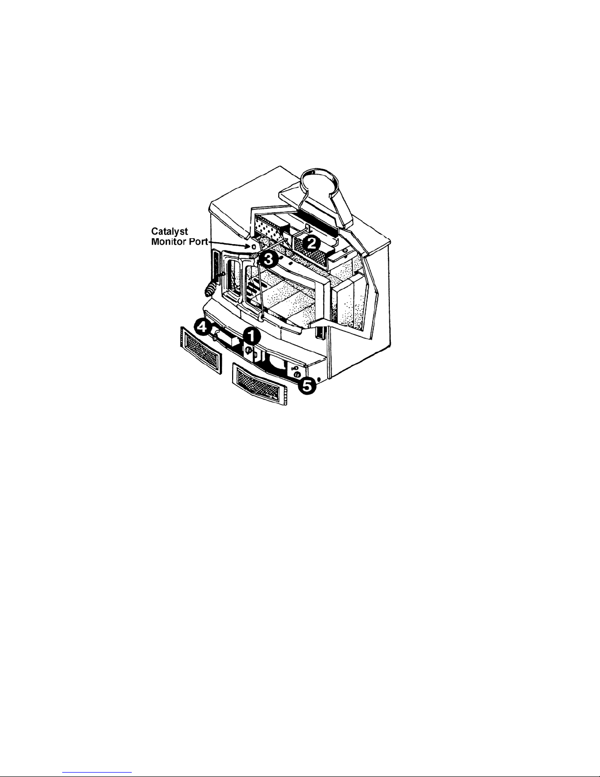
Familiarize yourself with the components of your stove before installation and operation. This owner’s
manual has been designed to assist you in installing, operating and maintaining your Energy King
stove efficiently and safely. Keep it in a safe place for future reference.
1. Manual Draft Control. Controls burn rate by regulating air entering the stove. It is located
beneath the loading door. Turn the control all the way to the right for maximum air intake, burn
rate and heat output, and all the way to the left for minimum air intake and heat output, with a low
burn rate.
2. Catalytic Combustors. The wood heaters contain catalytic combustors, which need periodic
inspection and replacement for proper operation. It is against the law to operate these stoves in a
manner inconsistent with operating instructions in this manual or if the catalytic element is
deactivated or removed. The catalytic combustors in these stoves are designed to burn the
smoke, carbon monoxide and particulate, which are not burned by the fire. Once the fire has
been established you can engage the catalytic combustors by shutting the bypass. (Minimum
catalytic light off will not occur until the stove reaches 500 degrees F.) (See the instructions on
page 21 for replacement of the catalytic combustors.)
3. Bypass. The bypass control is located above the loading door. The bypass control should be
pulled out all the way to allow smoke to bypass the catalytic combustor when first starting a fire
and until the unit reaches the 500-degree temperature necessary for light off. The catalytic
bypass should also be pulled out all the way when loading the stove with fuel.
4. Ash Pan. Designed for easy clean up of ash accumulation. Do not operate the stove with the
ash pan open, always keep it closed.
5. Blower. The blower is designed to provide additional heating value and forced air convection.
Three speeds allow easy adjustment.
2
Installation Materials Needed for Your Safety
(Freestanding Stoves)
Chimney Connector. Also known as flue pipe or stovepipe, the chimney connector joins the stove to
the chimney. It should be 6 inch diameter, minimum 24 MSG black or 25 MSG blued steel.
Thimble. A manufactured or site-constructed device installed in combustible walls and ceilings
through which the chimney connector passes to the chimney. It is intended to keep walls from
igniting.
Chimney. You must use either an approved masonry chimney or a prefabricated 6-inch listed high
temperature (tested to 2100 degrees F.) residential and building type heating appliance chimney per
UL 103 or ULC S629. The chimney size should not be less than or more than three times greater
than the cross-sectional area of the flue collar. Components required by manufacturers for
installation such as the chimney support base, firestop (as appropriate), attic insulation shield,
insulated tee, etc., are necessary to assure a safe chimney installation. Use only components
manufactured for the chimney.
Floor Protector
Stove. Use a listed floor protector or any non-combustible material.
Insert. Use a listed floor protector or material having a thermo conductivity of K-O.84 BTU – inches
per foot square – hour – Fahrenheit degrees; or equivalent to 3/8” non-asbestos millboard.
Fireplace Insert Installation
Specifications – Model Bay 2000C
Height 23 ¾”
Width 33”
Depth 24”
Weight 460 lbs.
Maximum Log Size 21”
Minimum Fireplace Dimensions
Height 23 ¾”
Width 32”
Depth 16”
Surround Dimensions
Height 32” Width 45”
Heating Capacity
Low Burn Rate 11,400 BTU/Hr.
High Burn Rate 34,600 BTU/Hr.
Weighted Average Particulate Emissions Overall Efficiency 78.5%
2.5 grams per hour
(Unit was tested with blower, three-speed switch)
Efficiency calculated per CSA B415 Standard
3

Clearances to Combustibles
Model Bay 2000C Fireplace Insert
A To Mantle 18”
B To Side Trim 9”
C To Top Trim 14”
D To Sidewall 16”
E Hearth Pad Extension to front 16”
F Hearth Pad Extension to Side 8”
Refer to NFPA 211 for clearance reduction methods.
4
Venting System
Proper draft must be provided for your Energy King unit. Draft is the force that moves air from the
stove up through the chimney. The amount of draft in your chimney depends on the length of the
chimney, local geography, nearby obstructions, and other factors. Too little draft may cause
backpuffing into the room and plugging of the chimney or catalyst.
The Energy King fireplace insert model Bay 2000C is intended only for installation into a masonry fireplace
constructed in accordance with the requirements of the Standard for Chim neys, Fireplaces, Vents and Solid Fuel
Burning Appliances, NFPA No. 211, or applicable local code requirements. Please consult local building and
fire officials about fire restrictions and installation requirements. FOR USE WITH SOLID FUEL ONLY.
5
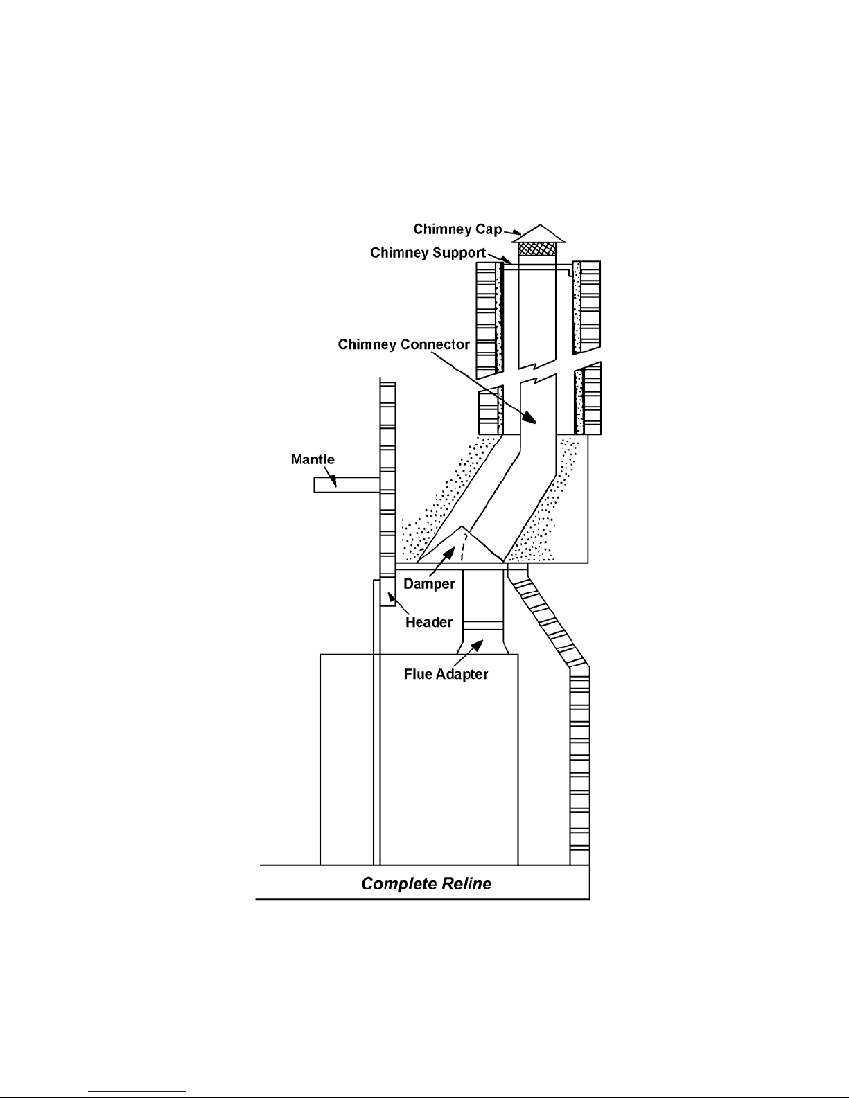
Connection to a Masonry Fireplace
There are several kits available to connect the stove to a masonry fireplace. Look for a listed kit. The
kit is an adapter that is installed at the location of the fireplace damper. The existing damper may
have to be removed to allow installation of the kit. The key points of this type of stove connection are,
first, the connector pipe must extend up the chimney above where the fire clay liner starts. Secondly,
the areas of the kit installation and connector penetration should fit tightly and be sealed with high
temperature furnace cement unless the kit’s instructions state otherwise.
The tight fitting installation aids the proper draw of the chimney.
DO NOT REMOVE BRICKS OR MORTAR FROM MASONRY FIREPLACE. INSTALL AND USE
ONLY IN MASONRY FIREPLACE. USE A LISTED FLOOR PROTECTOR OR ANY NONCOMBUSTIBLE MATERIAL. FIREPLACE INSERT FLOOR PROTECTOR MUST EXTEND AT
LEAST 8 INCHES TO EACH SIDE OF UNIT AND 16 INCHES IN FRONT.
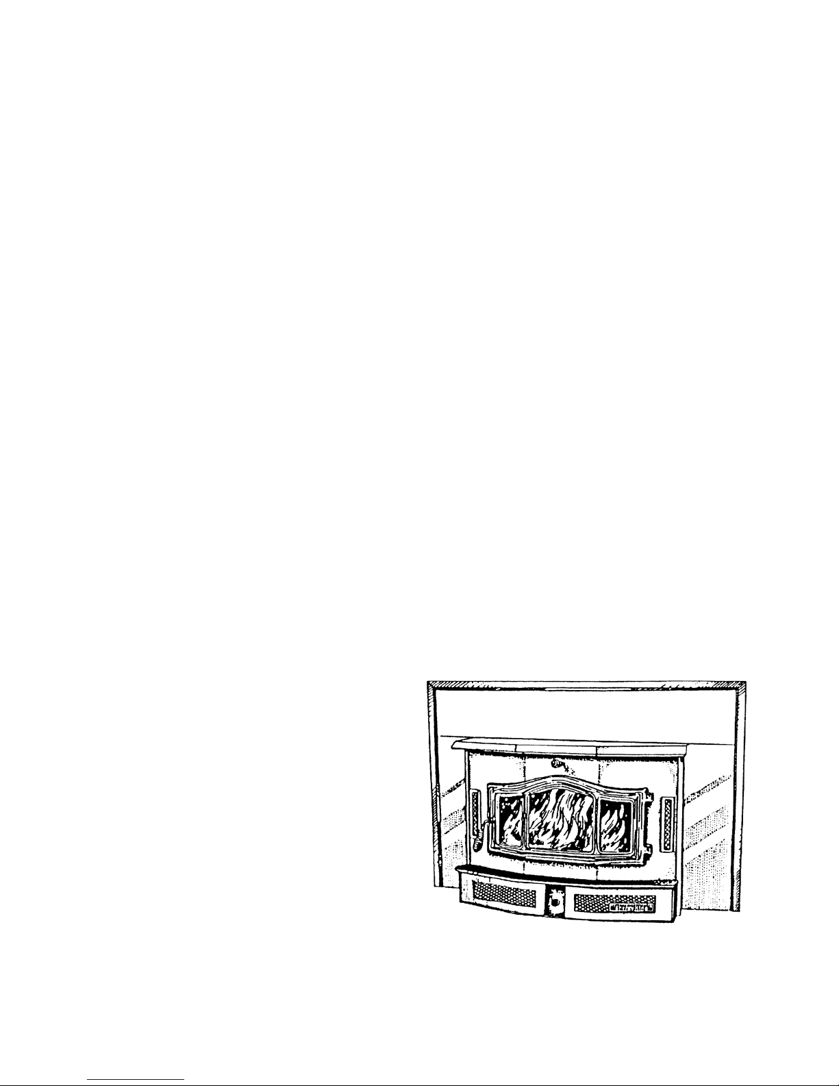
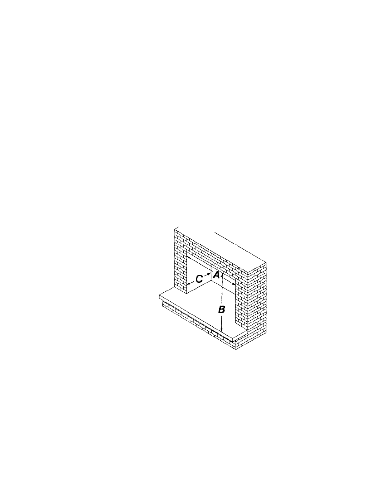
The Bay 2000C will insert into any masonry
fireplace that is at least (A) 32” wide, (B) 24” high,
and (C) 16” deep.
Before Installation
1. Check to make sure your masonry fireplace and chimney are in safe condition. Check the
chimney for cracks, loose mortar, and other signs of deterioration and blockage. The insert
should not be installed until it is determined that the chimney is safe for use. Since an oversized
flue contributes to the accumulation of creosote, the size of the flue should be checked to
determine that it is not too large for the insert.
The fireplace must be constructed to meet UBC Chapter 37 standards.
2. Clean the fireplace thoroughly.
3. Remove damper plate or block into open position with a non-combustible material.
4. Flue and chimney should be cleaned before installation.
6

Mount Trim Panels
5. Measure from back of the unit to the front and mark on the sides the location of the support angle.
6. Place the angle on the side of the unit and mark the holes for the locking screws. Drill three 3/16”
holes and bolt in place on both sides of the unit.
7. Bolt side trim panels to the support angle with screws and tinnerman nuts.
8. Mount top panel to side panel.
Brass Trim
9. Place side brass pieces on the side of the trim panels and cut to length.
10. Place top brass piece on top trim panel and cut to length.
11. Place brass corner piece over the side and top pieces. Mark and drill two 3/16” holes through
brass.
12. Drill one 3/16” hole near the bottom of each side brass piece.
13. Using six brass bolts and nuts, bolt brass trim to trim panels.
14. Place insulation around trip panels. Slide insert into masonry fireplace. Be sure to center and
level unit in place. Push tight against fireplace front. Make sure unit is in far enough to allow
proper chimney hookup, and smoke outlet is behind fireplace lintel to assure safe operation. If
brick is rough, additional insulation may be needed. Use only HIGH HEAT insulation approved for
woodburning stoves and inserts.
Direct Connect
The 8” obround connection (cast iron) must be bolted securely to the fireplace and fastened to the
chimney liner. A 6” offset direct connection must be used when the installation utilizes a 6” flexible
stainless liner.
7

Freestanding Stove Installation
Specifications – Model Bay 2000C
Height 35”
Width 33”
Depth 24”
Weight 510 lbs.
Maximum Log Size 21”
Heating Capacity
Low Burn Rate 11,400 BTU/Hr.
High Burn Rate 34.600 BTU/Hr.
Efficiency
Weighted Average Particulate Emissions
2.5 grams per hour
Overall Efficiency 78.5%
Efficiency calculated per C.S.A. B 415 Standard
The Bay 2000C Freestanding Stove must be connected
to a listed high temperature (2100 degrees F) residential
type and building heating appliance chimney per US 103
or ULC S629 or an approved masonry chimney with a
flue liner.
(Unit was tested with blower, three-speed switch.)
8
Base Assembly
To assemble as a stove, you need to bolt the base to the bottom of the unit using five ¼”
self-tapping screws.
Remove door, brick and grate. Set unit on its back to mount the base. Place base with slotted holes
towards the unit and line up with punched holes on the bottom of the unit. Use the five ¼” self-tapping
bolts to mount securely.
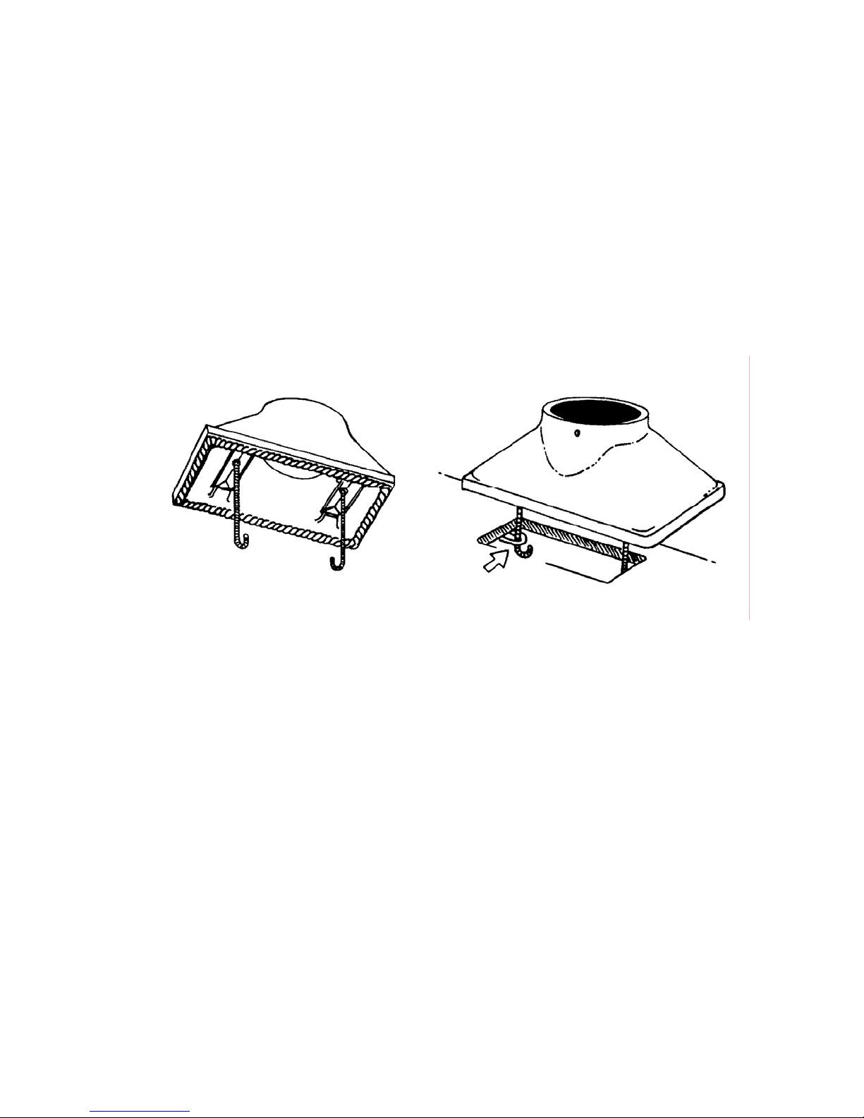
Flue Adaptor
The flue adaptor must be secured atop the unit for freestanding stove installation.
To attach the adaptor:
1. Attach the flat gasket to the adapter.
2. Set the flue adapter onto the top of the flue opening.
3. Center the adapter evenly over the flue.
4. Locate the two J shaped threaded screws. Remove the nut and washer from each. Set them
aside.
5. Lower the J shaped screws into the flue adapter opening, and insert each through the holes in the
adapter and stove.
6. Reaching inside the flue adapter, replace the nut and washer on each J shaped screw.
7. Tighten securely, using a wrench.
9
 Loading...