

ENERGY KINETICS SYSTEM 2000 Ascent Combi, SYSTEM 2000 Ascent Plus Combi, SYSTEM 2000 Ascent EK1T+ Owners And Installation Manual
ASME certified by EKI.
Certificate plate is under
the jacket on the steel
vessel.
National Board
Listed
.
MH28303
UL 726;
Low-Press Boiler
For Polypropylene Venting
Energy Kinetics is an ENERGY
For Conventional Venting
Ascent™ Combi and
Ascent™ Plus Combi
STAR® Partner and a leading
manufacturer of ENERGY
Ascent Oil – August 2019 1
STAR® heating equipment.
Model EK1T & EK1T+ Oil Fired
OWNER AND INSTALLATION MANUAL
Energy Kinetics, Inc.
www.energykinetics.com
INSTALLER: HANG THIS INSTRUCTION MANUAL AND ACCESSORY INSTRUCTIONS VISIBLY NEXT
TO THE BOILER USING THE SUPPLIED POUCH.
Boilers
Manufactured By:
51 Molasses Hill Road
Lebanon, NJ 08833
(908) 735-2066

HOMEOWNER/USER: READ AND SAVE THIS INSTRUCTION MANUAL AND ACCESSORY INSTRUCTIONS FOR
WARNING:
Have the burner/boiler started up and serviced at least once annually by a qualified service technician.
Professional care is necessary to properly service your equipment and verify it is operating reliably.
Failure to properly maintain the equipment could result in severe personal injury, death or substantial
property damage.
WARNING:
You must keep the area around the burner/boiler free from the following. Failure to comply could result in
severe personal injury, death or substantial property damage due to potential fire, explosion or equipment
damage from corrosive flue products.
Do not store or use gasoline or other flammable vapors or liquids near or in the same room as the
burner.
Do not use or store laundry products, paint, varnish, thinner or other such chemicals near or in the
same room as the burner/boiler. These chemicals cause creation of acids in the burner, heat
exchanger and vent system that can cause severe damage.
Do not store combustible materials near or in the same room as the boiler or any other combustion
appliance.
CAUTION:
DO NOT TAMPER WITH THE UNIT OR CONTROLS – CALL YOUR SERVICE PERSONNEL.
WARNING:
Improper installation, adjustment, alteration, service or maintenance can cause property damage,
personal injury (exposure to hazardous materials) or loss of life. Refer to the user’s information manual
provided with this boiler. Installation and service must be performed by a qualified installer, service
agency or the oil supplier (who must read and follow the supplied instructions before installing, servicing,
or removing this boiler. This boiler contains materials that have been identified as carcinogenic, or
possibly carcinogenic, to humans).
FUTURE REFERENCE.
PLEASE READ THIS FIRST
Special Attention Flags
Please pay particular attention to the following flags when you see them throughout this manual.
DANGER: Notifies you of hazards that WILL cause severe personal injury, death or substantial property damage.
WARNING: Notifies you of hazards that CAN cause severe personal injury, death or substantial property damage.
CAUTION: Notifies you of hazards that WILL or CAN cause minor personal injury or property damage.
NOTICE: Notifies you of special instructions on installation, operation, or maintenance that are important, but not
normally related to injury or property damage hazards.
Best Practice: Suggestions of best practices developed over many years of experience by professionals.
WARNING: Installation and service must be performed by a qualified installer, service agency or the oil supplier.
Retain this manual for use by your qualified service technician only. Should you observe unusual or
abnormal operation of the burner or boiler, contact your qualified service technician immediately. Do not
attempt to service or repair this product yourself.
WARNING: If the information in this manual is not followed exactly, a fire or explosion may result, causing property
damage, personal injury or loss of life.
WARNING: Do not store or use gasoline or other flammable vapors and liquids in the vicinity of this
or any other oil appliance.
Provide unobstructed combustion air openings sized and located per boiler manual and
applicable codes.
Ascent Oil – August 2019 2

Homeowner/User: General care and maintenance of your boiler:
Please read through the information provided for you in this manual. Ask your qualified service technician to explain
normal operation of your equipment.
Daily inspect the space around the burner/boiler to verify the area is clean and free of the materials listed above.
Monthly watch the operation of your burner/boiler through an operating cycle to verify normal operation. If you notice
unusual conditions or equipment behavior, contact your qualified service technician. Follow the instructions on the
next page to shut down the burner/boiler while waiting for the technician.
Ascent Oil – August 2019 3

TABLE of CONTENTS
TABLE of CONTENTS .............................................................................................................................................................. 4
HOMEOWNER/USER NOTE: ................................................................................................................................................... 5
RECORD OF INSTALLATION .................................................................................................................................................. 6
SCOPE ...................................................................................................................................................................................... 6
INSTALLER NOTE: .................................................................................................................................................................. 7
ASCENT COMBI and ASCENT PLUS COMBI BOILER ......................................................................................................... 8
PRINCIPLE OF OPERATION ................................................................................................................................................... 8
RECEIVING and UNPACKING ................................................................................................................................................. 9
LOCATION and CLEARANCE ................................................................................................................................................. 9
COMBUSTION AIR ................................................................................................................................................................. 10
CONVENTIONAL CHIMNEY VENTING – ASCENT COMBI ONLY ...................................................................................... 11
L-VENT CHIMNEY – ASCENT COMBI ONLY ....................................................................................................................... 12
POLYPROPYLENE VENTING – ASCENT PLUS COMBI ONLY .......................................................................................... 12
FUEL SYSTEMS ..................................................................................................................................................................... 12
OIL BURNER SETTINGS ....................................................................................................................................................... 13
OIL BURNER MOUNTING ...................................................................................................................................................... 13
GENERAL ASSEMBLY .......................................................................................................................................................... 14
ZONE CONTROL .................................................................................................................................................................... 17
BOILER BYPASS CIRCULATOR........................................................................................................................................... 18
FILLING WITH WATER, VENTING, and PURGING .............................................................................................................. 18
BOILER WATER TREATMENT .............................................................................................................................................. 19
ANTI-FREEZE ......................................................................................................................................................................... 19
WINTERIZING ......................................................................................................................................................................... 19
LINE VOLTAGE WIRING DIAGRAMS ................................................................................................................................... 20
WIRING and CONTROLS ....................................................................................................................................................... 21
ELECTRICAL CONNECTION - LINE VOLTAGE ................................................................................................................... 21
LOW VOLTAGE WIRING ........................................................................................................................................................ 21
HYDROSTAT CONTROL SETTINGS .................................................................................................................................... 21
ADVANCED SETTINGS ......................................................................................................................................................... 22
SELECTING ADVANCED SETTINGS .................................................................................................................................... 22
EMERGENCY WIRING ........................................................................................................................................................... 23
TROUBLESHOOTING THE SAFETY PRESSURE SWITCHES (ASCENT PLUS ONLY) .................................................... 24
PREPARE FOR START UP .................................................................................................................................................... 25
START UP PROCEDURE ....................................................................................................................................................... 25
BOILER OPERATION AND SAFETY CHECKS .................................................................................................................... 25
OIL BURNER OPERATION .................................................................................................................................................... 26
ANNUAL TUNE UP & INSPECTION ...................................................................................................................................... 27
HOT WATER MAINTANENCE ............................................................................................................................................... 31
REPLACEMENT PARTS ........................................................................................................................................................ 32
Ascent Oil – August 2019 4

HOMEOWNER/USER NOTE:
EMERGENCY SHUT DOWN INSTRUCTIONS:
Turn power off to boiler by switching the “Oil Burner Emergency Switch” (typically located at the top of basement
stairway or at boiler room entrance) to the OFF position. Shut off oil supply valve.
NOTICE
Do not use this boiler if any part has been under water. Immediately call a qualified service technician to inspect the
boiler and to replace any part of the control system which has been under water and replace any other parts that may pose
a safety risk.
IN CASE OF NO HEAT
In case of no heat coming from the boiler, perform the following actions or call a qualified service agency for help.
Look at the LEDs on the burner control. If the screen shows “LOCKOUT” or the red LED is on (constantly on the
Beckett Genisys or legacy controls), then press and hold in the reset button for one second. The burner will then
try to relight. If the burner relights successfully, then no further action is needed.
If the burner goes into lock out again, contact a qualified service agency for help.
ANNUAL MAINTENANCE
The Ascent Combi boiler requires an annual tune-up by a qualified service agency to maintain top efficiency and peak
performance and to verify proper performance of all safety devices.
PERIODIC MAINTENANCE
The Ascent Combi boiler requires minimal attention from the user.
- Daily inspect the space around the burner/boiler to verify the area is clean and free of any flammable or combustible
materials.
- Once a month it is recommended that the owner/user inspect the boiler and to watch the operation of the boiler. The
owner/user should:
Inspect flue connections.
o Look for evidence of deterioration from corrosion or other sources. Watch the flue pipes during a startup of the
boiler and look and smell for evidence of escaping flue products.
o For a chimney installation, particularly examine the joint between the boiler outlet and the flue pipe. Also
examine the joint between the flue pipe and the base of the chimney.
Inspect for evidence of water, such as leakage from the safety pressure relief valve.
Watch the Ascent Hydrostat control during one heating cycle of the boiler.
Verify the pressure gauge on the boiler is reading between 5 psi and 30 psi.
Verify the temperature gauge on the boiler reads no more than 220F at the end of a heating call.
If any of the above items seem unusual or out of the ordinary, then immediately call your qualified service agency.
Ascent Oil – August 2019 5

RECORD OF INSTALLATION
INSTALLER NAME:
INSTALLER ADDRESS:
INSTALLER CITY, STATE:
DATE INSTALLED:
NOTES:
SCOPE
This manual covers the Energy Kinetics Ascent Combi Boiler. The boiler is designed and equipped and has been
tested to generate hot water in a low pressure closed loop system. The boiler is a major component of a closed loop
system that can be used as a heat source for hydronic, radiant, domestic hot water, spa, and/or pool heating systems. Call
Energy Kinetics to obtain piping and wiring instructions for applications, such as hydronic heating, radiant heating, domestic
hot water, swimming pool heating, multiple boilers, primary/secondary injection loops, etc. The installer of the system is
responsible for the final design of the system and for adding the balance of the needed parts to complete the system.
COMMONWEALTH OF MASSACHUSETTS
When the boiler is installed within the Commonwealth of Massachusetts:
This product must be installed by a licensed plumber
If antifreeze is used, a reduced pressure backflow preventer device shall be used.
Ascent Oil – August 2019 6

INSTALLER NOTE:
ALL INSTALLATIONS MUST BE MADE IN ACCORDANCE WITH ALL NATIONAL, STATE AND LOCAL,
PLUMBING, HEATING AND ELECTRICAL CODES THAT MAY DIFFER FROM THIS MANUAL AND IN
ACCORDANCE WITH THE FOLLOWING CODES, AS APPLICABLE:
N.F.P.A. No. 70: National Electrical Code A.N.S.I. / N.F.P.A. No. 211: Chimneys, Fireplaces, Vents and Solid Fuel
Burning Appliances
A.N.S.I. / N.F.P.A. No. 31: Installation of Oil Burning Equipment
If this oil fired boiler is converted to gas fired by field mounting a listed gas conversion burner, then install in
accordance with A.N.S.I. Z223.1/N.F.P.A. No. 54: National Fuel Gas Code
These codes are available from:
National Fire Protection Association
1 Batterymarch Park
Quincy, MA 02269-9101.
A hot water boiler installed above radiation level or as required by the Authority having jurisdiction, must be
provided with a low water cutoff device.
A boiler should be installed in such a manner that, if the pressure vessel or any connection thereto should leak,
the resulting flow of water will not cause damage to the area in which it is installed.
A hot water storage tank should be installed in such a manner that, if the storage tank or any connection thereto
should leak, the resulting flow of water will not cause damage to the area in which it is installed.
A boiler’s pressure relief valve, hot water storage tank T&P relief valve, backflow preventer, and all other
devices must be piped to the nearest drain to avoid damage in the event the valve is actuated.
Make sure relief discharge pipes from all reliefs are properly placed to safely contain discharge. Make sure
relief discharge pipes, such as from a boiler or a hot water storage tank, will safely contain hot water and/or
boiling water. Make sure relief discharge pipes, such as from a boiler or a radiant heating system, will safely
contain water treated with boiler chemicals and/or antifreeze. Reliefs include the boiler pressure relief valve, the
back flow preventer discharge port, and the domestic hot water tank temperature and pressure relief valve. Any
other reliefs, such as from radiant heating systems, must also follow these guidelines.
Ascent Oil – August 2019 7

ASCENT COMBI and ASCENT PLUS COMBI BOILER
IMPORTANT MESSAGE TO HOMEOWNER/USER: These instructions should be carefully read and kept for future
reference to gain the best performance from your Ascent Combi boiler.
CONGRATULATIONS ON YOUR PURCHASE OF THE ASCENT BOILER with its highly efficient low mass hydronic
heat exchanger, the Energy Converter. It is the product of years of engineering and advanced design, which brings
together in a single system all elements needed to provide efficient home heat and hot water. This operation and
maintenance information has been prepared so that you may better understand and use your Energy Kinetics Ascent
Boiler and Heating System.
PRINCIPLE OF OPERATION
The Ascent Combi Boiler comprises a heat source, the energy converter, circulating water, and an on demand
domestic hot water plate heat exchanger. The Ascent Plus Combi Boiler additionally includes an expanded heat transfer
surface and extended flue pass with a power venter that uses dilution air to allow advanced polypropylene venting.
The Boiler maintains a minimum temperature (in stock configuration, see “advanced settings”) until a heating zone or
zone controller (supplied by Energy Kinetics or sourced locally) signals a call for heat, or the domestic water flow switch
signals hot water flow in excess of about ½ GPM. The Ascent Hydrostat control receives the call for heat or hot water and
turns on the heat and/or hot water/bypass circulators, and turns on the burner if the boiler is not hot enough to satisfy the
demand.
The Ascent Energy Converter is the product of advanced thermal engineering. It is designed with two separate
passageways, nearly 8 feet long, coiled around each other. Water travels along one passageway from your home toward
the center of the unit and heated gases travel from the unit center toward the vent. This is a “forced circulation counterflow” design and it provides very efficient transfer of heat from the burning fuel to the circulating water. The superior
insulation of the boiler minimizes heat losses to the surroundings, resulting in directing heat to your home in an efficient and
quiet manner.
Ascent Combi and Ascent Plus Combi have high annual efficiency because they are very well insulated low mass
designs with a moderate amount of water so excess heat is not wasted as is commonly found in cast iron and steel boilers.
They are also designed to produce domestic hot water at much lower temperatures than those required in tankless coil
boilers, allowing significantly lower idle temperatures and lower heat loss in standby mode.
Your Ascent boiler begins to supply heat and hot water almost instantly. This rapid response means that your rooms
can be heated quickly to temperature. The Ascent Combi can heat water with up to 175,000 BTU/hr (140,000 BTU/hr for
the Ascent Plus Combi) input, enough for two simultaneous showers in a typical house with standard flow fixtures. With the
factory installed backflush and cleaning ports, the boiler and plate heat exchanger may be easily serviced to keep peak hot
water production for the life of the system.
A modern retention head oil burner fires into the center of the Ascent boiler where a high temperature, stainless steel
alloy combustion chamber provides ideal conditions for “near perfect” and efficient combustion.
The Ascent Boiler is designed with a hinged front cover that allows full access to the inside of the boiler for inspection
and cleaning. All access for pressure vessel service is from the front, so the Combi Boiler can be placed near a wall or into
a closet.
Ascent Oil – August 2019 8
TIP:
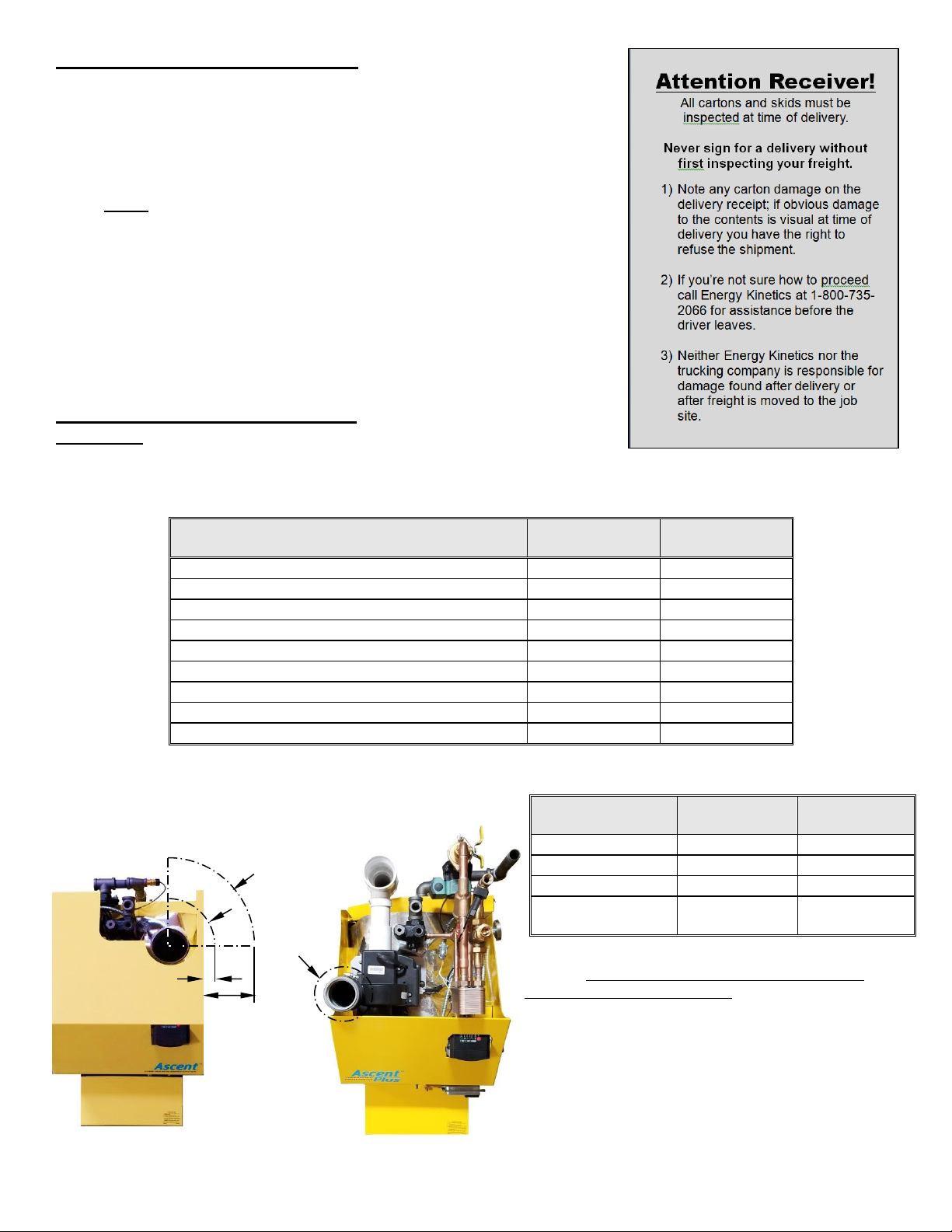
RECEIVING and UNPACKING
Installation Clearances from Boiler Surfaces,
Inches
Clearance to
Combustibles
Clearance for
Service
Front of boiler (not including burner)*
10”
20”
Left side of boiler body
0
5”
Right side of boiler body
0
12”
Back of boiler body
4”
4”
Top of boiler body
10”
16”
Bottom of boiler legs to floor
0
0
Ascent Combi L-Vent: from flue pipe “A”
3”
3”
Ascent Combi Standard Flue: from flue pipe “B”
9”
9”
Ascent Plus Combi Polypropylene “C”
0”
0”
Ascent Combi
Ascent Plus
Combi
Weight
377 lbs
405 lbs
Water Content
3 gallons
3 gallons
Air Inlet Pipe Size
2" PVC
3" PVC
Boiler Flue Outlet
5" Flue Pipe
3"
Polypropylene
Figure 1A, Top View of Boiler
Flue Connection Clearance to Combustibles
Ascent Combi
Ascent Plus Combi
C
B
7” A7/8”
Inspect shipment upon receipt for external damage. Walk
around the freight and identify and address any unusual signs of
handling with the shipper before signing for the delivery. This is
a fast and easy way to resolve all transportation damage claims.
When unpacking and uncrating, inspect each item for internal
damage. Any damage found should immediately be reported to the freight
carrier before installation. The receiver is responsible for following the claims
procedure of the freight carrier. The freight carrier is responsible for taking
prompt action on all claims. Replacements for parts damaged in shipment are
available upon receipt of a signed copy of a claim report (concealed damage
claims should be filed immediately against the freight carrier by the consignee).
After unpacking, check each item against the packing list. Inspect it
thoroughly for loose parts, instruction sheets and packing lists. Immediately
report any missing items. It is wise to complete the installation before discarding
packing material. Store all parts where they will not be damaged or lost prior to
installation.
LOCATION and CLEARANCE
DANGER: Provide clearance to combustible surfaces in accordance with all
local and national codes. Follow National Fire Protection
Association Bulletin NFPA Installation of Oil Burning Equipment
and all applicable codes.
Ascent Oil – August 2019 9
* Minimum recommended clearance to allow door to fully open.
Place the unit as near to the chimney or vent as
possible allowing clearance for front cleaning and
service as shown in Figure 1B. Installing the boiler with
the burner parallel to a wall is sometimes advisable to
allow access to front and rear components in spaces
with limited depth.
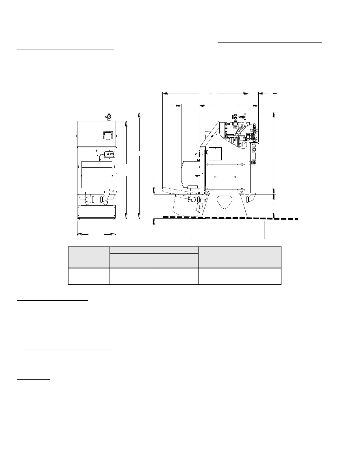
12"
40"
4
3
4
"
44
1
2
"
20"
52"
47
3
4
"
30"
"A"
"B"
Figure 1B - Boiler Clearance for Cleaning and Service
Burner
Dim “A”
Open Door
Leg Bottom to Floor
Clearance “B” (minimum)
W/O Silent
Burner Cover
With Silent
Burner Cover
Carlin EZ-1
9”
9-1/2”
12”
Level bottom of stand,
or slightly higher in back
Installations should utilize the Energy Kinetics boiler stand or a suitable solid, stable, level, and smooth foundation for the
boiler. If not using an Energy Kinetics supplied stand, provide a solid, level, and smooth foundation with clearance for door
opening and service. Place the unit as near to the chimney or vent as possible allowing clearance for front cleaning and
service as shown in Figure 1A and 1B. Installing the boiler with the burner parallel to a wall is sometimes advisable to allow
access to front and rear components in spaces with limited depth.
NOTICE: The Ascent Combi is manufactured with the BACK of the boiler higher than the front to assist in air removal. A
spirit level placed front to back on the lower side of the base near the floor will read level. The stand design compensates
and properly pitches the boiler ¼ to ½ a bubble off level, with the back of the boiler higher. Adjust the levelling feet or by
shimming the base at the floor as necessary.
COMBUSTION AIR
The Ascent Combi Boiler must be installed in an area where adequate fresh air is available to support combustion. An
optional sealed air box (Silent Burner Cover, included in the Combi Plus model) allows combustion air to be piped from
outside the building. Piping of outside air directly to the boiler is highly recommended because it completely isolates the
boiler from the home environment, it greatly reduces operating noise from the boiler, and it can lower idle loss in some
cases.
Boiler with outside air piping: In modern houses with tight construction, the connection of the Silent Burner Cover to
an outside air source to provide combustion air is highly recommended on the Ascent Combi. It is required on the Ascent
Plus Combi for sidewall vent installations. The outside air source should be located high enough above grade to be at least
12” above expected snow accumulation.
WARNING: Combustion air must be supplied for the Ascent Plus Combi for sidewall vent installations, although it is
optional for the Ascent Combi. It may be supplied with up to 50 feet in equivalent length through
polypropylene or PVC pipe. For the EK1T Ascent Combi use 2" pipe, and for the EK1T+ Ascent Plus Combi
use 3” pipe. Each 90 degree elbow is the equivalent of 5 feet of straight pipe. For example, if three 90
degree elbows are used, then the length of pipe run may be up to 35 feet. For longer runs up to 65
equivalent feet increase pipe size by 1"(to 3” for the Ascent Combi and to 4” for the Ascent Plus Combi). A
Tek-screwed or un-cemented joint allows the air inlet pipe to be disconnected so the swing down door may
open.
Ascent Oil – August 2019 10

WARNING: Modern buildings of tight construction, as well as the operation of attic and exhaust fans, kitchen ventilation
systems, clothes dryers or fireplaces may create conditions of unsatisfactory combustion or venting.
Provisions must be made to use combustion air that communicates with a well-ventilated attic or with the
outdoors (such as using a louver or grate). The opening should have a free area of not less than one (1)
Boiler without outside air piping:
square inch per 4,000 BTU per hour of the total input rating.
WARNING: The confined space shall be provided with two permanent openings, one near the top of the enclosure and
one near the bottom. Each opening shall have a free area of not less than one square inch per 1,000 BTU
per hour of the total input rating of all appliances in the enclosure, freely communicating with interior areas
having adequate infiltration from the outside.
CONVENTIONAL CHIMNEY VENTING – ASCENT COMBI ONLY
DANGER: Improper chimney installation or operation may cause flue gas leakage and/or carbon monoxide leakage,
which may lead to severe injury or death.
When connecting an Energy Kinetics Ascent Combi boiler to an existing chimney, be sure to follow all applicable local,
state, and national codes that may differ from this manual, and in accordance with the following codes, as applicable:
NFPA No. 31: Installation of Oil Burning Equipment
NFPA No. 211: Chimneys, Fireplaces, Vents and Solid Fuel Burning Appliances
If this oil fired boiler is converted to gas fired by field mounting a listed gas conversion burner, then install in accordance
with ANSI Z223.1/NFPA No. 54: National Fuel Gas Code
In retrofit installations, have chimney thoroughly cleaned. Carefully inspect chimney, base of chimney, and liner prior to
installation of the Ascent Combi Boiler.
WARNING: Masonry chimneys must have a tile or metal liner. The liner must:
1) Extend above the masonry.
2) Have an insulating air gap, isolating the liner from the chimney, allowing for rapid heat-up and draft
establishment.
3) Be sealed at each joint to prevent air infiltration and damage from condensation.
NOTICE: Inspect Chimney and Chimney base after initial three months of heating season.
The installation of a chimney cap is recommended. The base of the chimney must always have a drop leg below the
flue connector to allow scale and condensation to accumulate without blocking the flue pipe. Do not block the flue opening
by inserting the flue connecter too deeply into the chimney.
Best Practice: If drop leg is in excess of 12 inches deep, backfill with loose gravel or sand to obtain a maximum of 12-inch
depth. Use of fiberglass insulation to backfill the drop leg is also a practical method. All cleanout doors should be closed,
and if practical also sealed with silicone, to prevent cold air entry into chimney. Cleanout doors that are sealed with silicone
can still be opened every tune up to inspect and clean the drop leg, and then resealed with silicone for another year. Pay
particular attention to cleanout doors that are located out of doors.
CAUTION: If liner is not sound or if existing tile liner fails to contain intermittent condensation, or if excessive debris is
found at the base of the chimney, then it is recommended to install a properly sized metal liner approved for use with oil
heat appliances.
The metal liner diameter and length should be as recommended by the metal liner manufacturer. Corrugated metal
liners should be at least 5”diameter for EK1T Ascent Combi (a 6” diameter chimney liner may be required at 1.25 GPH firing
rate). Energy Kinetics has 5” flexible metal chimney connectors available to be used between the boiler flue collar and the
chimney. Call Energy Kinetics for details on metal liners.
Chimney connectors should be positioned to create the shortest possible run of flue pipe to the chimney. If a 6”
diameter chimney liner is used, it is recommended that the chimney connector be 6” diameter too by using a short piece of
5” pipe and a 5” to 6” adapter close to top cover opening. The overall horizontal length of flue piping should not exceed 15
feet. Long runs or low firing rates may require insulated flue pipe such as L-Vent or All-Fuels to keep the temperature at
base of chimney adequate for draft and to prevent corrosion of piping and connectors.
Because the Ascent Combi boiler uses a power burner, the flue pipe may experience some positive pressure on start
up. Energy Kinetics recommends that all pipe joints be sealed with high temperature silicone sealant to ensure passage of
all combustion products to the chimney.
Normally, pitch horizontal flue pipe up toward chimney approximately ¼” per foot. For existing installations, it is
permissible for the flue connection of the boiler to be higher than the chimney thimble, provided adequate draft is
established.
Ascent Oil – August 2019 11
 Loading...