

ENERGY KINETICS EK3 Frontier Owners & Installation Manual
EK3 Frontier
Oilheat Commercial Boiler
Owner & Installation Manual
Manufactured By:
Energy Kinetics, Inc.
51 Molasses Hill Road
MH28303
UL 726;
CAN/CSA-B140.7-05
CAN/CSA-B140.0-03
CAN/CSA-B139-M91
Low-Press Boiler
INSTALLER: HANG THIS INSTRUCTION MANUAL AND ACCESSORY
INSTRUCTIONS VISIBLY NEXT TO THE BOILER USING THE
SUPPLIED POUCH.
OWNER: READ AND SAVE THIS INSTRUCTION MANUAL AND ACCESSORY
INSTRUCTIONS FOR FUTURE REFERENCE.
Lebanon, NJ 08833
(908) 735-2066
www.energykinetics.com
Seventh Edition October 2015
National Board Listed
ASME Certified

Please Read This First…..
Special Attention Flags
Please pay particular attention to the following flags when you see them throughout this manual.
DANGER: Notifies you of hazards that WILL cause severe personal injury, death or substantial property damage.
WARNING: Notifies you of hazards that CAN cause severe personal injury, death or substantial property damage.
CAUTION: Notifies you of hazards that WILL or CAN cause minor personal injury or property damage.
NOTICE: Notifies you of special instructions on installation, operation, or maintenance that are important, but not
normally related to injury or property damage hazards.
WARNING: Retain this manual for use by your qualified service technician only. Should you observe unusual or
abnormal operation of the burner or boiler, contact your qualified service technician immediately. Do
not attempt to service or repair this product yourself.
WARNING:
WARNING:
Have the burner/boiler started up and serviced at least once annually by a qualified service
technician. Professional care is necessary to properly service your equipment and verify it is
operating reliably. Failure to properly maintain the equipment could result in severe personal injury,
death or substantial property damage.
You must keep the area around the burner/boiler free from the following. Failure to comply could
result in severe personal injury, death or substantial property damage due to potential fire, explosion
or equipment damage from corrosive flue products.
Do not store or use gasoline or other flammable vapors or liquids near or in the same room
as the burner.
Do not use or store laundry products, paint, varnish, thinner or other such chemicals near or
in the same room as the burner/boiler. These chemicals cause creation of acids in the
burner, heat exchanger and vent system that can cause severe damage.
Do not store combustible materials near or in the same room as this boiler
combustion appliance.
CAUTION:
WARNING:
DO NOT TAMPER WITH THE UNIT OR CONTROLS – CALL YOUR SERVICE PERSONNEL.
Improper installation, adjustment, alteration, service or maintenance can cause property damage,
personal injury (exposure to hazardous materials) or loss of life. Refer to the user’s information
manual provided with this boiler. Installation and service must be performed by a qualified installer,
service agency or the gas supplier (who must read and follow the supplied instructions before
installing, servicing, or removing this boiler. This boiler contains materials that have been identified
as carcinogenic, or possibly carcinogenic, to humans).
General care and maintenance
Please read through the information provided for you in this manual. Ask your qualified service technician to
explain normal operation of your equipment.
Daily inspect the space around the burner/boiler to verify the area is clean and free of the materials listed
above.
Periodically watch the operation of your burner/boiler through an operating cycle to verify normal operation. If
you notice unusual conditions or equipment behavior, contact your qualified service technician. Follow the
instructions on the next page to shut down the burner/boiler while waiting for the technician.
or any other
EK3 Frontier Boiler Manual 1 Seventh Edition- October 2015

TABLE OF CONTENTS
Page Topic Page Topic
1
2
3
3
4
5
6
6
7
7
7
8
8
9
9
9
9
10
10
11
11
11
11
11
11
12
12
12
12
13
13
Please read this first
Table of Contents
Owner/User Note
Emergency Shut Down Instructions
Record of Installation
System 2000 EK3 Frontier Boiler
Principle of Operation – System 2000
Principle of Operation - Digital Manager
Receiving and Unpacking
Moving the Boiler
Location and Clearance
Combustion Air
Chimney Venting
L-Vent Chimney
Side Wall/Power Venting
Fuel Systems
Oil Burner Settings
Oil Burner Mounting
Beckett CF 500 Oil Burner Operation
Aquastat Settings
General Assembly
Boiler Mounting
Zone Control
Boiler Bypass Circulator
Filling with Water, Venting and Purging
Boiler Water Treatment
Anti-Freeze
Winterizing
Piping & Wiring Diagrams
Wiring and Controls
Electrical Connection – Line Voltage
14
14
14
14
15
15
16
17
18
19
19
20
20
20
20
21
21
22
23
24
24
24
25
27
35
38
42
43
44
Back
Cover
Prepare for Start Up
Digital Manager, Install
Digital Manager, Low Voltage Wiring
Start Up Procedure
Digital Manager Option Switch Settings
Security System Interface Wiring
10 & 15 Zone Manager Install Instructions
Digital Manager Operation
Digital Energy Manager Check
2 Minute Digital Manager Diagnostics
Additional Manager Tests
Digital Manager Sensor Testing
Line Voltage Relays
Line Voltage
Surge Suppression
Trouble Shooting with the Digital Manager
Operation without the Digital Manager
Diagnostics with the Digital Manager
Annual Maintenance
Amulet Replacement
Flame Former Replacement
Replace Parts
SYS-08-019 EK3 w/Dig Mgr, w/Single Zone Inj
SYS-08-020 EK3 w/Dig Mgr, w/Heat & DHW & Inj
SYS-08-021 EK3 w/Dig Mgr, w/Heat & DHW
SYS-04-019 Mult EK3 Boiler Installation
Common Flue Pipe Sizing
EK3 Frontier Boiler Spec Drawing
Footprint Drawing, Four EK3 Boilers
Limited Five Year Warranty for
Commercial/Industrial Boilers
EK3 Frontier Boiler Manual 2 Seventh Edition- October 2015

OWNER/USER NOTE:
EMERGENCY SHUT DOWN INSTRUCTIONS:
Turn power off to boiler by switching the “Oil Burner Emergency Switch” (typically located at the
top of basement stairway or at boiler room entrance) to the OFF position. If unable to locate the “Oil
Burner Emergency Switch” then switch the “System Emergency Switch” located at the boiler, on the
left hand side of the system junction box located on the top right hand side of the boiler. Shut off oil
supply valve.
NOTICE
Do not use this boiler if any part has been under water. Immediately call a qualified service technician to inspect
the boiler and to replace any part of the control system and any gas control which has been under wate r.
IN CASE OF NO HEAT
In case of no heat coming from the boiler, perform the following actions or call a qualified service
agency for help.
Look at the Digital Manager and write down all lights showing on the Digital Manager.
o Refer to the Digital Manager Operation Summary for the meaning of the lights.
o Reset the Digital Manager by turning off and back on the System Switch on the left side
of the Manager.
Remove the burner cover and look at the two LEDs on the burner control. If the red LED is on
constantly, then press and hold in the reset button for one second. The burner will then try to
relight. If the burner relights successfully, then no further action is needed.
If the burner goes into lock out again, contact a qualified service agency for help.
ANNUAL MAINTENANCE
The SYSTEM 2000 boiler requires an annual tune-up by a qualified service agency to maintain top efficiency and
peak performance and to verify proper performance of all safety devices.
PERIODIC MAINTENANCE
The SYSTEM 2000 boiler requires minimal attention from the user.
- Daily inspect the space around the burner/boiler to verify the area is clean and free of any flammable or combustible
materials.
- Once a month it is recommended that the owner/user inspect the boiler and to watch the operation of the boiler. The
owner/user should:
Inspect flue connections.
o Look for evidence of deterioration from corrosion or other sources. Watch the flue pipes during a start up of
the boiler and look and smell for evidence of escaping flue products.
o For a chimney installation particularly examine the joint between the boiler outlet and the flue pipe. Also
examine the joint between the flue pipe and the base of the chimney.
Inspect for evidence of water, such as leakage from the safety pressure relief valve.
Watch the Digital Manager during one heating cycle of the boiler.
Verify the pressure gauge on the boiler is reading between 5 psi and 30 psi.
Verify the temperature gauge on the boiler reads no more than 220F at the end of a heating call.
If any of the above items seem unusual or out of the ordinary, then immediately call your qualified service agency.
EK3 Frontier Boiler Manual 3 Seventh Edition- October 2015

EK3 Owner & Installation Manual
RECORD OF INSTALLATION
INSTALLER NAME:
INSTALLER ADDRESS:
INSTALLER CITY, STATE:
DATE INSTALLED:
NOTES:
SCOPE
This manual covers the Energy Kinetics System 2000 EK3 Frontier Boiler. The boiler is designed and
equipped and has been tested to generate hot water in a low pressure closed loop system. The boiler is a
major component of a closed loop system that can be used as a heat source for hydronic heating, hydronic air
handler, radiant, domestic hot water, spa, and/or pool heating systems. Call Energy Kinetics to obtain piping
and wiring instructions for applications, such as hydronic heating, radiant heating, domestic hot water,
hydronic air handler, swimming pool heating, multiple boilers, injection loops, etc. The installer of the system
is responsible for the final design of the system and for adding the balance of the needed parts to complete the
system.
COMMONWEALTH OF MASSACHUSETTS
When the boiler is installed within the Commonwealth of Massachusetts:
This product must be installed by a licensed plumber
If antifreeze is used, a reduced pressure backflow preventer device shall be used.
INSTALLER NOTE:
ALL INSTALLATIONS MUST BE MADE IN ACCORDANCE WITH ALL NATIONAL, STATE AND LOCAL,
PLUMBING, HEATING AND ELECTRICAL CODES THAT MAY DIFFER FROM THIS MANUAL AND IN
ACCORDANCE WITH THE FOLLOWING CODES, AS APPLICABLE:
N.F.P.A. No. 70: National Electrical Code
A.N.S.I. / N.F.P.A. No. 31: Installation of Oil Burning Equipment
A.N.S.I. / N.F.P.A. No. 211: Chimneys, Fireplaces, Vents and Solid Fuel Burning Appliances
Canadian Electrical Code, Part I
If this oil fired boiler is converted to gas fired by field mounting a listed gas conversion burner, then install in
accordance with A.N.S.I. Z223.1/N.F.P.A. No. 54: National Fuel Gas Code
These codes are available from:
National Fire Protection Association
1 Batterymarch Park
Quincy, MA 02269-9101.
Canadian Standards Association
5060 Spectrum Way
Mississauga, Ontario
L4W 5N6
CANADA
A boiler should be installed in such a manner that, if the pressure vessel or any connection thereto should leak, the
resulting flow of water will not cause damage to the area in which it is installed. A boiler’s pressure relief valve,
backflow preventer, and all other devices must be piped to the nearest drain to avoid damage in the event the valve is
actuated.
EK3 Frontier Boiler Manual 4 Seventh Edition- October 2015
Sixth Edition October 2010
SYSTEM 2000® EK3 FRONTIER OILHEAT BOILER - COMMERCIAL - RESIDENTIAL
IMPORTANT MESSAGE: These instructions should be carefully read and kept for future reference to gain the best
performance from your System 2000 Frontier boiler.
CONGRATULATIONS ON THE PURCHASE OF A SYSTEM 2000 BOILER with its highly efficient low mass
hydronic heat exchanger, the Energy Converter. It is the product of years of engineering and advanced design, whi ch
brings together in a single system all the elements needed to provide an efficient source for heat and hot water. This
operation and maintenance information has been prepared so that you may better understand and use your Energy
Kinetics Frontier Boiler and Heating System.
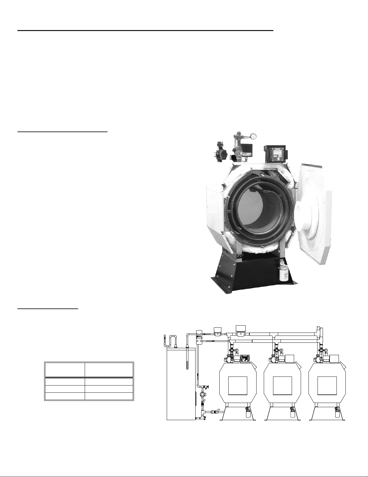
The EK3 Frontier is ASME certified and National Board listed, perfect for commercial installations. The
required manual reset high temperature limit and the manual reset low water cutoff are both included. The boiler is
packaged with circulators, piping, controls, wiring, and burner mounted. The boiler will fit through a 34” doorway.
The EK3 Frontier comes with the System 2000 Digital Manager control system with built in energy recovery
cycle.
Oil Heat EK3 Packages Include:
Energy Converter (boiler) Flue 7” at 45 degrees,
Front Service, thru side swing door, right side hinge.
EK3 Firing Rates: 2.25 gph to 3.00 gph,
Beckett CF500 Burner
o Primary control with oil delay
o Oil valve
o 20,000 peak volt Igniter
o 1/3 HP burner motor
o Two stage ‘B’ fuel pump
One Flexible Oil Line
Wiring Harness w/ Door Switch and Service Outlet
o Manual reset high temperature limit
o Manual reset low water cutoff
Complete supply, return, bypass piping
o Bypass Circulator, Taco 007
o Injection Circulator, Taco 0012IFC
o Air Purge with two (2) Air Vents
o T&P Gauge
o One (1) 3/4” Drain Valve
o ASME 30 psi Relief Valve
Cold start, cold finish operation with energy recovery
Return temperature sensor for condensing protection
Relay for control of injection circulator included.
EK3 Options Include:
Air Inlet Box kit for field mounting
Smart oil filter kit
Fabricated steel base
Additional flex oil line (required for 2 pipe installs)
Domestic hot water making is an option, consult
the factory for hot water zone kits.
Input (GPH)
Gross Output
(BTU/hr)
2.25 272,000
2.60 313,000
3.00 357,000
EK3 with Digital Manager,
Easy access, front opening door.
SYSTEM 2000
HEAT EXCHANGER
Shown with optional base
MODEL 18U
LEBANON, NJ 08833
SYSTEM 2000
ENERGY MANAGER
THERMOSTAT
HEATING
HOT WATER
Z4
THW
1
1
ZHW
T1
2
2
Z1
T2
3
3
Z2
T3
Z344A1
A2
24VAC
CHIMNEYLESS
ONLY
INDUCER
TEMP. SENS.
IND
B
BURNER
EN
ERGY
B1
S
KIN
ETICS
CIRCULATOR
Lebanon, New Jersey
B2
R
POWER
190
CIRC
T4
170
CAUTION
160
150
24 VAC CONNECTION ONLY.
140
READ INSTRUCTIONS BEFORE
130
MAKING ANY CONNECTIONS
120
100
ALARM
T
R
A
M
S
R
E
L
T
I
F
EK3 Frontier Boiler Manual 5 Seventh Edition- October 2015
T
R
A
M
S
R
E
L
T
I
F
T
R
A
M
S
R
E
L
T
I
F

SYSTEM 2000 - PRINCIPLE OF OPERATION
SYSTEM 2000 comprises a heat source, the energy converter, circulating water, and five (or more) zones controlled
by an electronic control, the Digital Manager.
The Boiler sits cold until a thermostat calls for heat. The Digital Manager receives the call for heat and turns on the
bypass circulator and burner. Water circulates within the boiler as it warms up to operating temperature. When ready,
the supply circulator and zone valve(s) open and deliver heat to the zone(s) calling for heat. When the thermostats are
satisfied, the Digital Manager turns off the burner and enters the energy recovery stage. The circulators and zone valve
stay energized to deliver the heat remaining in the boiler to the last zone calling or to the domestic hot water storage tank.
When energy recovery is complete and the Boiler has been cooled off, the Digital Manager turns off the system and
waits for another thermostat (or tank aquastat) to call for heat. SYSTEM 2000 runs the burner only when you need heat
and delivers that heat only where you need heat.
The System 2000 Energy Converter is the product of advanced thermal engineering. It is designed with two separate
passageways, nearly 18 feet long, coiled around each other. Water travels along one passageway from the heat emitters
toward the center of the unit. Heated gases travel from the unit center toward the chimney. This is a “forced circulation
counter-flow” design and it provides very efficient transfer of heat from the burning fuel to the circulating water. The
superior insulation of the boiler minimizes heat losses to the surroundings, resulting in heat directed to the desired zones
in an efficient and quiet manner.
SYSTEM 2000 has an extremely high annual efficiency (over 99% of steady state) because it runs only when your
heat zones or hot water storage tank needs heat. Energy recovery is completed at the end of each heat call, virtually
eliminating off cycle losses.
Your System 2000 holds a minimal quantity of water so it begins to supply heat in about two minutes. This rapid
response means that your rooms can be heated quickly to temperature. The System 2000 EK3 Frontier can provide
heated water up to 357,000 BTU’s per hour.
A modern retention head oil burner fires into the center of System 2000 where a high temperature, light weight
ceramic flame former provides ideal conditions for “near perfect” efficient, pollution-free combustion. Your S ystem 2000
is tightly sealed so all products of combustion pass only to the chimney.
DIGITAL MANAGER - PRINCIPLE OF OPERATION
The left side of the Manager is the input side, which provides 24-volt power supply and connections for thermostats.
The right side is the output side, which starts the burner, circulators, zone valves or zone circulators and the domestic hot
water circulator. See photo of the Manager on the cover.
Lights on the Digital Manager indicate zone(s) calling for heat (left side) and (right side) lights in dicate active zone(s),
burner operation and circulator operation. These function lights are an aid in servicing. The following is a typical cycle.
1. SYSTEM WAITING FOR A CALL: The boiler is turned off and sits cold, waiting until a call for heat. The red power
light on the Manager is glowing.
2. CALL FOR HEAT: A room thermostat call starts the cycle. The thermostat light on the left side will turn on for that
zone.
3. PRE-HEAT: Output lights for the bypass circulator and burner turn on, the bypass circulator starts, and the burner
begins firing. Water circulates within the boiler and through the bypass as it warms up to operating temperature.
4. HEAT: Once the boiler water has heated up to 140º F (about two minutes), the Manager will turn on the zone output
light on the right side. The zone valve will open, the main supply (injection) circulator will start and hot water will flow
to the zone needing heat. The burner runs as long as there is a thermostat calling and as long as heat is being
delivered to the zone. The burner may shut off if the return temperature exceeds 170º F/190º F (RED burner light
turns off) or if the high limit temperature is exceeded (RED burner light stays on, but the high limit aquastat shuts the
burner off).
5. ANOTHER CALL FOR HEAT: If another zone calls for heat while the burner is already running and the return
temperature is above 140F, the zone output will turn on, immediately supplying heat to the zone.
6. MONITOR RETURN TEMPERATURE: The Manager continually senses the return temperature and will turn off the
zone outputs if the return temperature drops below 120º F (130º
closed, the boiler water will quickly reheat and once the return temperature reaches 140º F (150º
is ON), then the Manager will reopen the zone valve and start the supply circulator.
7. THERMOSTAT SATISFIED: The thermostat light on the left side will go out. The burner light and the burner will then
turn off.
8. ENERGY RECOVERY: The bypass circulator, main supply (injection) circulator, and zone valve remain energized.
The circulating water will remove the energy from the converter, sending the heat to the last zone that called. The
energy recovery stage continues until the return temperature has dropped sufficiently or until maximum timing has
been reached. The boiler is now sitting cold, waiting for the next call for heat. Maximum timing for heat recovery
stage is usually set at twenty minutes for space heating zones and is fixed at five minutes for the Hot Water zone.
(See Digital Manager Option Switch Settings).
F if Option Switch #1 is ON). With the zone outputs
F if Option Switch #1
EK3 Frontier Boiler Manual 6 Seventh Edition- October 2015
RECEIVING and UNPACKING
Inspect shipment upon receipt for external damage. When unpacking and uncrating, inspect each item for internal damage.
Any damage found should immediately be reported to the freight carrier before installation. The receiver is responsible for
following the claims procedure of the freight carrier. The freight carrier is responsible for taking prompt action on all claims. If
freight cannot be inspected at the time of delivery, sign the bill of lading “Subject to Inspection” and inspect the shipment as
soon as possible after receipt. Replacements for parts damaged in shipment are available upon receipt of a signed copy of a
claim report (concealed damage claims should be filed immediately against the freight carrier by the consignee).
After unpacking, check each item against the packing list. Inspect it thoroughly for loose parts, instruction sheets and
packing lists. Immediately report any missing items. It is wise to complete the installation before discarding packing material.
Store all parts where they will not be damaged or lost during installation.
MOVING THE BOILER
The boiler is shipped bolted to a pallet. Use a pallet jack or fork lift to move the boiler while mounted on the pallet. The
boiler has two features designed to help with moving the boiler. There are four welded in nuts at the top of the front and rear
covers that can be used to screw in eyebolts or lifting bolts. Use a chain hoist or cherry picker to lift the boiler. The boiler legs
have four holes to accept 3/4” iron pipe. Remove the boiler drain from underneath the front of the boiler and slide (2) 6 foot
pieces of 3/4” iron pipe into the holes from side to side of the boiler. Use the two pipes to lift, steer, and stabilize the boiler. Use
of a wheeled dolly or cart is recommended once the boiler has been removed from the pallet.
If the front door and burner are removed, then the boiler can be hand trucked from the front and will fit through a 34” door.
Use pieces of wood (4x4’s) to space the boiler shell from the hand truck uprights, so the mounting studs and the junction box
will be protected.
The boiler is 33” wide and will fit through a 34” door when moving from front to back. If the front door and burner are
removed and the manual reset aquastat on the rear is removed, the boiler will be 32” front to back and will fit through a 33” door
when moving sideways. If the aquastat well on the rear is also removed, then the boiler will be 31” front to back and will fit
through a 32” door when moving sideways. When the front door has been removed, the door mounting studs will be exposed
and can be easily damaged unless proper care is taken. It is recommended that pieces of wood be attached to help protect the
studs from impact.
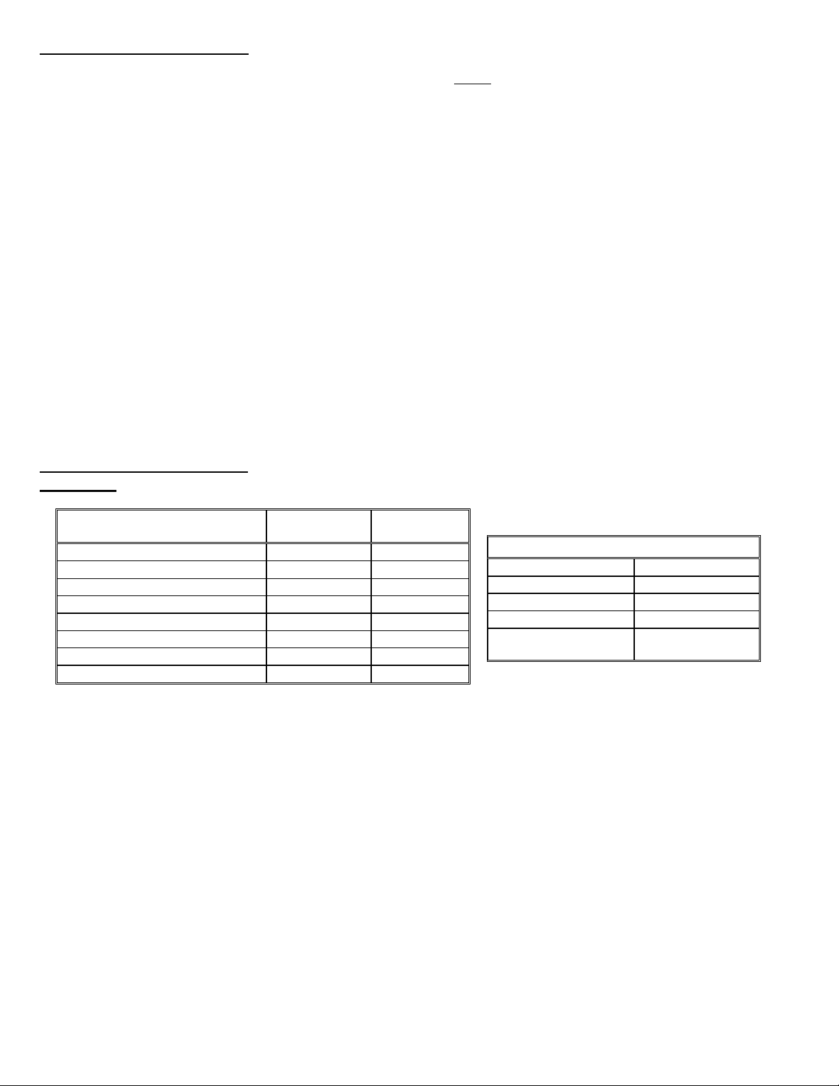
LOCATION and CLEARANCE
DANGER: Provide clearance to combustible surfaces in accordance with all local and national codes. Follow National Fire
Protection Association Bulletin NFPA Installation of Oil Burning Equipment and all applicable codes.
Installation Clearances from
Boiler Surfaces, Inches
Front of boiler 13 36*
Left side of boiler body 0 2
Right side of boiler body 0 16*
Back of boiler body 7 36
Top of boiler body 13 16
Bottom of boiler legs to floor 0 0
L-Vent: from flue pipe 3 3
Standard Flue: from flue pipe 9 9
* Minimum recommended clearance to allow door to fully open.
Clearance to
Combustibles
Clearance for
Service
Boiler Weight and Water Content
Weight 675 lbs
Water Content 7-1/2 gallons
Air Inlet Pipe Size 4 "
Boiler Flue Outlet 7 “
Supply & Return
Piping
1-1/2”
EK3 Frontier Boiler Manual 7 Seventh Edition- October 2015

COMBUSTION AIR
The System 2000 Boiler must be installed in an area where adequate fresh air is available to support co mbustion.
The EK3 Frontier can be provided with a sealed Air Box that can be piped to air outside the building.
Boiler with outside air piping: Piping of outside air directly to the boiler is highly recommended becau se it completely
isolates the boiler from the interior environment, as well as greatly reducing operating noise from the boiler. In multiple
boiler installations, each boiler air intake should be piped separately. The outside air source must be located high enough
above grade to be at least 12” above expected snow accumulation. Use 4” PVC to pipe in the fresh air, 20 feet max and
five 90 degree elbows or less. Up to 40 feet max using 5” PVC and five 90 degree elbows or less.
Boiler without outside air piping:
WARNING: The confined space shall be provided with two permanent openings, one near the top of the enclosure and
one near the bottom. Each opening shall have a free area of not less than one square inch per 1,000 BTU
per hour of the total input rating of all appliances in the enclosure, freely communicating with interior areas
having adequate infiltration from the outside.
WARNING: Modern buildings of tight construction, as well as the operation of attic and exhaust fans, kitchen ventilation
systems, clothes dryers or fireplaces may create conditions of unsatisfactory combustion or venting.
Provisions must be made to use combustion air that communicates with a well-ventilated attic or with the
outdoors (such as using a louver or grate). The opening should have a free are a of not less than one (1)
CHIMNEY VENTING
square inch per 4,000 BTU per hour of the total input rating.
WARNING: Masonry chimneys must have a tile or metal liner. The liner must:
1) Extend above the masonry.
2) Have an insulating air gap, isolating the liner from the chimney, allowing for rapid heat-up and draft
establishment.
3) Be sealed at each joint to prevent air infiltration and damage from condensation.
NOTICE: Inspect Chimney and Chimney base after initial three months of operation.
The installation of a chimney cap is recommended. The base of the chimney must always have a drop leg below the
flue connector to allow scale and condensation to accumulate without blocking the flue pipe.
CAUTION: If drop leg is in excess of 12 inches deep, backfill with loose gravel or sand to obtain a maximum of 12-
inches depth. All clean out doors must be sealed to prevent cold air entry into chimney.
In retrofit installations, have chimney thoroughly cleaned. Carefully inspect chimney, base of chimney, and liner prior
to installation of System 2000 Boiler.
CAUTION: If liner is not sound, or if existing tile liner fails to contain intermittent condensation, or if excessive debris is
found at the base of the chimney, then it is recommended to install a properly sized metal liner approved for use with oil
heat appliances.
The metal liner diameter and length should be as recommended by the metal liner manufacturer. Corrugated metal
liners should be at least 8" diameter. Connection of a flexible metal liner directly to the flue collar of the boiler is an
acceptable connection method and is recommended. Alternatively, a flexible metal vent connector may be used between
the flue collar of the boiler and a flexible metal liner. Call Energy Kinetics for details on metal liners.
Chimney connectors should be positioned to create the shortest possible run of flue pipe to the chimney. The overall
horizontal length of flue piping should not exceed 15 feet. Long runs or low firing rates may require insulated flue pipe
such as L-Vent or All-Fuels to keep the temperature at base of chimney adequate for draft and to prevent corrosion of
piping and connectors.
Because the System 2000 boiler uses a power burner, the flue pipe may experience some positive pressure on start
up. Energy Kinetics recommends that all pipe joints be sealed with high temperature silicone sealant to ensure passage
of all combustion products to the chimney.
Normally, pitch horizontal flue pipe up toward chimney approximately ¼” per foot. For existing installations, it is
permissible for the flue connection of the boiler to be higher than the chimney thimble, provided adequate d raft is
established.
If a minimum of +0.08” w.c. draft overfire is not present after sufficient burner run time to heat up the chimney, there is
a problem that will need to be corrected. Call Energy Kinetics for help resolving draft problems. Under normal
circumstances, there is NO need for a DRAFT REGULATOR and one should not be installed. Call Energy Kinetics with
questions about flue pipe sizing.
WARNING: No solid fuel appliance or fireplace should be installed in a flue common with this heating appliance. The
flue gas exit of the venting system must be at least three (3) feet above the point at which it passes through the roof and
at least two (2) feet higher than any portion of a building within 10 feet horizontally of its location.
EK3 Frontier Boiler Manual 8 Seventh Edition- October 2015

L-VENT CHIMNEY
SYSTEM 2000 Boilers typically have flue gas temperatures between 350º F and 450º F during normal operation.
Due to the low flue gas temperatures, L-Vent chimney pipe is suitable for use with SYSTEM 2000 Boilers. L-Vent
chimney pipe may require smaller chase dimensions than other chimney pipe materials and should be considered for new
installations with SYSTEM 2000 Boilers. Call Energy Kinetics for help locating sources of L-Vent.
1. L-Vent must be U.L. Listed to U.L. 641.
2. L-Vent to be installed in accordance with the vent manufacturer’s instructions.
3. System 2000 and L-Vent must be installed in strict compliance with all State and Local Codes and with the
regulations of the authorities having jurisdiction, which may differ from and which take precedence over these
instructions or the vent manufacturer’s instructions.
SIDE WALL/POWER VENTING
Energy Kinetics currently does not offer a kit for sidewall venting or power venting of the EK3 Frontier.
FUEL SYSTEMS
NOTICE: Inspect and if needed, replace oil lines according to local codes. Oil lines must be absolutely airtight. Use
only flared joints on all copper tubing and use thread sealant suitable for oil on all iron pipe threaded joints. Do not use
Teflon tape on fuel system joints. Check all joints and connections for leaks after installation. A high quality fuel filter
should be installed in the fuel line. A high quality UL Listed 10-micron fuel filter is recommended. When changing the
fuel filter, be sure to lubricate cartridge gasket with motor oil, not heating oil.
It is recommended that Frontier systems be equipped with a (optional) fuel filter and a (optional ) flexible fuel line. Call
Energy Kinetics to obtain optional UL Listed fuel filter and optional UL Listed flexible fuel line. The flexible fuel line allows
the door to open without disconnecting the fuel supply. The flexible line connects the fuel pump to the Smart Filter. The
fuel filter can be mounted on the right hand side of the standard base. A fusible link shutoff valve should be installed at
the inlet of the fuel filter or as required by the authority having jurisdiction. If the oil supply is higher than the burner, then
an anti-siphon valve (OSV) should be installed.
All piping systems should conform with pump manufacturer’s specifications that are attached to each new pump. The
burner is capable of burning No. 1 or No. 2 heating oil.
CAUTION: DO NOT USE GASOLINE, CRANKCASE DRAININGS, OR ANY OIL CONTAINING GASOLINE.
NOTICE: Order an additional flexible fuel line for two-pipe systems. A two-stage pump is required if lift from oil tank
exceeds approximately ten (10) feet. Follow instructions provided by pump manufacturer on single and two pipe
connections for bypass plug usage and other specific installation requirements.
CAUTION: ALWAYS KEEP THE OIL SUPPLY VALVE SHUT OFF IF THE BURNER IS SHUT DOWN FOR AN
EXTENDED PERIOD OF TIME.
OIL BURNER SETTINGS
EK3 Frontier Boilers are shipped from the factory preset for 2.25 GPH firing rate. The SYSTEM 2000 Boiler can be
fired over a range of firing rates to suit the needs of the application. The following table lists approximate settings for oil
burners based on testing performed at Energy Kinetics.
CAUTION: Final settings for each burner and firing rate for a particular installation must be determined by using
combustion test equipment and following the instructions given under "Start Up Procedure".
CAUTION: The EK3 Frontier has been tested for use with chimney venting. Consult factory for sidewall vent
applications.
Model
Input
GPH
Nozzle @ Pump Pressure
Output
Btu/Hr
Beckett CF 500
2.25* 2.00 Hago 45º P@ 130 psi 272,000 Head: 0.5 Shutter: 4.0 Band: 0.0
EK3
2.60 2.25 Hago 45º P@ 135 psi 313,000 Head: 1.5 Shutter: 5.5 Band: 0.0
3.00 2.50 Hago 45º P@ 145 psi 357,000 Head: 2.5 Shutter: 7.0 Band: 0.0
* Factory Setting
EK3 Frontier Boiler Manual 9 Seventh Edition- October 2015

OIL BURNER MOUNTING
The burner is premounted at the factory. If field installation or replacement of Energy Kinetics supplied burner is
required, follow these instructions. Start by checking nozzle and electrode position per manufacturer’s specifications prior
to assembly to unit. The EK3 Frontier boiler uses the Beckett CF500 burner. The CF500 burner will accept the Frontier
amulet, EK part number 10-0718. The amulet must be modified by trimming back the inside front edge. The inside front
edge has a lip designed to protect the head. The CF500 head requires that the inside lip be trimmed flush with the insid e
diameter of the amulet. Test fit the amulet by inserting the amulet into the boiler opening. If the amulet doesn't easily
slide into the boiler, then gently sand the outside diameter of the amulet until it will fit into the boiler opening. Test fit the
amulet onto the burner head. The amulet for the Beckett CF500 burner has smooth interiors. If the amulet is a tight fit on
the burner head, then slightly moisten inside the amulet with water.
Place a 1/2" bead of retort cement onto the burner tube at the flange to air tube joint, and slide the (moistened)
amulet over the burner head and against the flange. Ensure proper seating of the amulet by pressing the amulet onto the
burner with a flat object. If needed, trim the front edge of the amulet to be recessed behind the front shroud of the burner
head. Leave the excess retort cement at the amulet to flange joint and the cement will provide an airtight seal of the air
tube flange to the boiler face. If needed, add extra retort cement to seal the air tube flange to the boiler face and to the
insulation inside the boiler door. The EK3 does run with some positive pressure in the combustion a rea and enough
retort cement must be used to provide a proper seal against that positive pressure.
Once the amulet has been seated and trimmed, and retort cement added, then install the burner into the boiler by
carefully inserting the air tube with amulet into the boiler opening while aligning the burner flange holes with the boiler
studs. Install flat washers and nuts onto the boiler studs and tighten all nuts evenly.
BECKETT CF500 OIL BURNER OPERATION
NOTICE: For reliable operation, set Air-Fuel mixture conservativ ely based on installation conditions. CO2/O2
and draft readings should be taken through 1/4" test port in front jacket opening just to right of burner. Sample tube mu st
extend at least eight (8) inches into front cover to obtain accurate readings. Smoke test and stack temperature should be
taken at flue outlet.
NOTICE: For accurate efficiency calculations, measure flue gas temperature in flue pipe. Overfire temperatures will
be higher than flue gas temperature measured in the flue pipe. Be sure to measure CO
stack temperature at the flue outlet. If using a digital flue gas analyzer, use a separate thermocouple inserted into the flue
outlet to measure flue temperature while drawing the gas sample from the over fire port.
Installation Conditions CO
Normal Conditions
Active Area (Washer, Dryer, Shop)
Outside Oil Tank
12.5% 4.2%
12.2% 4.6%
12.0% 4.9%
Setting O2 Setting
2
Note 1: For combinations of above, use lowest CO2 level or highest O2 level.
Note 2: When Air Box is used, CO
must be checked with air box cover in place.
2
AFTER 15 MINUTES RUNNING, CHECK AND RECORD:
1. DRAFT AT FLUE OUTLET …………………………………. -0.02” to -0.12” w.c.
2. DRAFT AT OVER FIRE ……………………………… +0.08" to -0.02” w.c.
3. DRAFT LOSS ……………………………… 0.06" to 0.10” w.c.
4. CO
………………………………………………………………. See table above
2/O2
5. STACK TEMPERATURE …………………………………………. 350
6. SMOKE TEST …………………………………………………….. Verify 0 smoke at breech
Draft over fire with a chimney should be -0.02” to +0.08” w.c.
If not, recheck chimney, chimney base and flue pipe for blockage or clean out door openings.
Draft Loss Definition: The draft loss through boiler is found by subtracting the overfire draft reading from the breech
draft reading. For example, if the breech draft is -0.04" w.c., and overfire draft is +0.02" w.c., then subtracting the two
readings gives a draft loss of 0.06" w.c., which is acceptable. If the draft loss exceeds 0.10" w.c., then the boiler may
need to be cleaned or there may be some other blockage that will need to be addressed.
1. DANGER: Verify proper operation of high limit aquastat:
a. With a Digital Manager:
i. Remove all heat and hot water calls (No input lights on left side of manager).
ii. Turn System switch off, then remove red sensor lead from the left side quick connect.
iii. Restore power. The 100
shortly, in less than a minute.
iv. At approximately 205
o
light will flash on the manager’s temperature display, and the burner should start
o
F to 215o F, the high limit aquastat should shut off burner.
v. Turn off power and reconnect the red sensor lead.
2.
DANGER: Verify proper operation of boiler pressure relief valve by following instructions on pressure relief valve,
which calls for a 'try lever test'. Make sure discharge pipe is properly placed to safely contain discharge and open
relief valve using the try lever.
in the over fire port and the
2/O2
o
to 450o F
EK3 Frontier Boiler Manual 10 Seventh Edition- October 2015

AQUASTAT SETTINGS
With Digital Manager:
11D18 automatic reset high limit, set at 205 o F, 10F Differential (195 o F/205 o F)
L4006E manual reset high limit, set at 210
Or, Carlin EZ-Temp manual reset high limit, set at 210
DANGER: Double check that the manual reset high limit aquastat is set to 210
GENERAL ASSEMBLY
Assembly of various packaged units is illustrated throughout this manual. The use of non-Energy Kinetics supplied
pump, controls and accessories should follow good practices. The diagrams and locations presented in the manual are
recommended.
BOILER MOUNTING
PIPING SO THE DOOR CAN OPEN: To avoid conflicts with the door opening, piping should be in accordance with
the boiler specifications drawing and the piping schematics in this manual. The door opens to the right hand side of the
boiler. The burner and air box also need clearance when the door opens. Do not locate any piping in front of the boiler
unless clearance from the door is verified. This also applies to the oil line piping and the combustion air piping. NOTICE:
Air inlet pipe must be disconnected to allow door to swing open.
BOILER PITCH: The Frontier pressure vessel is manufactured with the rear higher to allow for proper air removal. This
pitch is carefully set at the factory when the boiler is built. Be sure to level the stand prior to mounting the boiler on a
stand. When the stand is level, the pitch is correct and the back of the boiler will be higher than the front.
ZONE CONTROL
ZONE CONTROL BY VALVE: The SYSTEM 2000 Boiler is designed to provide multi-zone control of the heating system
and optionally can supply domestic hot water. Energy Kinetics recommends full port, 24-volt zone valves for control of
each heating zone. A system with a single heating zone still requires a zone valve to provide control for preheat of unit
and to maintain minimum temperature during operation.
ZONE CONTROL BY CIRCULATOR: Zone control by circulators requires a flow valve, circul ator and 24-volt relay (fan
type such as Honeywell R8225B) for each zone. The boiler bypass circulator is still used in these cases.
NOTICE: Refer to piping schematic for location of zone circulators.
ZONE PURGING: Valves to isolate and purge individual zones should be installed according to good piping practices.
EXPANSION TANK SIZING: The type and size of expansion tank depends on the total system water volume. The EK3
Frontier contains 7-1/2 gallons of water.
NOTICE: Sizing must consider cold start and hot operation due to system concepts of energy recovery and rapid heat
up.
BOILER BYPASS CIRCULATOR
NOTICE: Systems are piped at the factory with the boiler bypass circulator. The bypass circulator piping
and wiring must not be changed from the factory configuration. The bypass circulator runs whenever the burner
is powered for heat and ensures the proper flow rate through the boiler.
FILLING WITH WATER, VENTING, and PURGING
When piping is completed and all accessories installed, the Converter and piping should be filled with water. The
Converter purges itself of air when properly installed. NOTICE: AIR VENT CAPS MUST REMAIN OPEN. Vent caps
should be removed and kept in a safe location. Each zone should be purged until a steady stream of water without air
passes out of purge hose. Vent all radiation.
NOTICE: DO NOT START BURNER UNTIL CONVERTER AND SYSTEM ARE FULL OF WATER. Fill to normal
cold system pressure, 10 to 12 psi on pressure gauge. Before placing system in operation, carefully check for leaks
throughout system. Tighten pipe joints, circulator flanges; check gaskets, etc., as needed.
o
F
o
F
o
F. Do not exceed a setting of 210 o F.
EK3 Frontier Boiler Manual 11 Seventh Edition- October 2015

BOILER WATER TREATMENT
Addition of boiler water treatment is recommended to reduce lime buildup inside the boile r. Energy Kinetics
recommends addition of one quart of 8-Way Boiler Treatment per 30 gallons system water. 8-Way Boiler Treatment is
recommended to treat water up to medium hardness. Call Energy Kinetics for more details about boiler water treatment
and about hard water conditions.
ANTI-FREEZE
Only non-toxic antifreeze (such as Propylene Glycol) should be used if adding anti-freeze to a system that produces
domestic hot water. Hard water should not be used in combination with generic antifreeze. Energy Kineti cs supplies a
quality inhibited Propylene Glycol anti-freeze with orange dye and an antifoam agent. 8-Way Boiler Treatment can be
added to Energy Kinetics anti-freeze and is recommended in areas of medium water hardness. NOTICE: Thoroughly
clean system prior to adding antifreeze. TSP is recommended for removing flux and other oil based compounds.
Once system has been cleaned and flushed, then add antifreeze to obtain approximately a 30% by volume mixture of
antifreeze in water. Call Energy Kinetics for assistance in calculating how much anti-freeze to add to system.
WINTERIZING
NOTICE: If the SYSTEM 2000 Boiler may be exposed to freezing temperatures, then anti-freeze should be added.
When a property is winterized by draining all domestic water piping, then the SYSTEM 2000 Boiler must be protected. It
is not recommended to drain the SYSTEM 2000 Boiler, because introducing air into the boiler can cause rusting inside
the boiler shell and also because the Energy Converter has a spiral water passage that can not be completely drained of
water. When draining the domestic water piping system, be sure to drain the domestic side of the plate heat exchanger.
If the hydronic system will not be drained, then add enough anti-freeze to protect the entire hydronic system including the
boiler, piping, radiation, circulators, etc. If the hydronic system will be drained, then add shut off valves to isolate the
boiler and add anti-freeze to the boiler only, as follows. Drain water from the boiler and then add anti-freeze to the boiler.
Refill boiler with water and run boiler circulator through the bypass to distribute antifreeze within boiler. Propylene Glycol
in water will provide the following freeze protection: 30% down to +8F, 40% to -8F, and 50% to -27F. Energy Kinetics
recommends using 30% anti-freeze to obtain the best boiler performance. Use over 30% anti-freeze only if lower
temperature freeze protection is mandatory. Caution: Always keep the fuel supply valve shutoff if the burner is shut
down for an extended period of time.
PIPING and WIRING DIAGRAMS
All piping and threaded accessory connections should follow good practice using approved joint sealants.
Use Energy Kinetics Smart Thread Sealant P/N 10-0620
Digital Manager Use the Digital Manager control with one or more zones directly off the boiler is needed and benefit
from the Digital Manager energy recovery cycle, such as for large load with multiple zones (5 10 & 15 zone versions
of the Digital Manager are available), primary/secondary injection (5 10 & 15 zone ERC Controls are avail able) with
multiple boilers, or as a dedicated hot water maker. The Digital Manager has built in condensing p rote ctio n. Tekmar
multiple boiler controls are recommended, for 2, 4, 9, or more boilers.
For piping and wiring boilers with a Digital Manager and single zone injection, refer to drawing SYS-08-019. This
drawing shows the factory wiring of the Digital Manager boiler.
For piping and wiring boilers with a Digital Manager with heat, domestic hot water and injection, refer to drawing
SYS-08-020. The factory wiring must be field modified per this drawing. The blue leads from the 24V relay mounted to
the system junction box must be moved. One from Z1 lug to the Circ lug and the other one wired in parallel with the zone
valve end switches which are fed from the 24VAC lug.
For piping and wiring boilers with a Digital Manager with heat and domestic hot water, refer to drawing SYS-08-021.
The factory wiring must be field modified per this drawing. The blue leads from the 24V relay mounted to the system
junction box must be moved. One from Z1 lug to the Circ lug and the other one wired in parallel with the zone valve end
switches which are fed from the 24VAC lug.
For piping and pipe sizing of Primary/Secondary Loops, refer to drawing SYS-04-019.
NOTE: When zoning with zone valves, make sure the piping/wiring configuration prevents “dead-heading ” of the 0012
system circlator. Four wire zone valves as shown in drawings SYS-08-020 and 08-021 use end switches to pull in a relay
that starts the system circulator after the valve has opened. A bypass installed on the end of the supply and return
headers that is adjusted by a ball valve allows 2 wire zone valves to be used as shown in drawing SYS-08-023.
EK3 Frontier Boiler Manual 12 Seventh Edition- October 2015

WIRING and CONTROLS
The Frontier Heating System is furnished with controls and basic accessories as illustrated and described in this
manual. Control, burner and accessory instruction sheets and system wiring diagrams should be attached to this manual
for future reference.
DANGER: All wiring must comply with the NEC and any local codes. All wiring for installations in Canada must be
done in accordance with the Canadian Electrical Code, Part I.
ELECTRICAL CONNECTION - LINE VOLTAGE
POWER SUPPLY: 120 VOLT 60 HZ, 15 Amperes
System 2000 requires 120 VAC. The supply voltage must be within 108 VAC min / 132 VAC max for reliable
operation of the boiler and the Manager. An easy way to check the supply voltage is to plug a voltmeter in at the service
outlet located on the side of the system junction box.
DANGER: Make All Connections with Power Off at Main Circuit Box
Connect power from a separate 15 AMP fused circuit. Install 3rd wire grounding for proper bond between all electrical
accessories. The system switch is included so power can be shut off at the unit for servicing.
the green pigtail to ground.
WARNING: The junction box is wired at the factory with the service outlet always powered, even with the System
Emergency Switch turned off. To have the service outlet controlled by the System Emergency Switch, move the service
outlet black lead to top lug of system switch. A manual reset low water cut-off is factory installed by Energy Kinetics.
Pigtails are provided for the line voltage power connection. Connect black pigtail to hot, white pigtail to neutral, and
EK3 Frontier Boiler Manual 13 Seventh Edition- October 2015
 Loading...