

ENERGY KINETICS EK2C, EK3C, EK1C Installation & Service Manual

front center of the vesse l.
MH27877
This product meets the
Board Listed
Accel CS features
access
Gas Fired Hot Water Boiler
EK1C, EK2C, EK3C
INSTALLATION & SERVICE MANUAL
INSTALLER: PLEASE HANG THIS INSTRUCTION MANUAL AND ACCESSORY INSTRUCTIONS VISIBLY
CONSUMER: PLEASE RETAIN THIS INSTRUCTION MANUAL AND ACCESSORY INSTRUCTIONS FOR
ANSI Z21.13b-2012
Low-Press Boiler
2MF1
NEXT TO THE BOILER USING THE SUPPLIED POUCH.
FUTURE REFERENCE.
Accel CS Boiler - Gas Heat - Eighth Edition – January, 2015
Accel CS
MANUFACTURED BY:
ENERGY KINETICS, INC.
51 Molasses Hill Road
Lebanon, NJ 08833
(908) 735-2066
www.energykinetics.com
Energy Star® guidelines
for efficiency.
™
Removable panels
for easy internal
National
ASME certified by EKI.
Certificate plate is on the
Please Read This First
Special Attention Flags
Please pay particular attention to the following flags when you see them throughout this manual.
DANGER: Notifies you of hazards that WILL cause severe personal injury, death or substantial property
damage.
WARNING: Notifies you of hazards that CAN cause severe personal injury, death or substantial property
damage.
CAUTION: Notifies you of hazards that WILL or CAN cause minor personal injury or property damage.
NOTICE: Notifies you of spec ial instructions on inst allation, operation, or maintenance that are important, but
not normally related to injury or property damage hazards.
BEST PRACTICE: Notifies you of recom mendations made by Energy Kinetics for the installers, which will help ensure
optimum operation and longevity of the equipment.
WARNING: If the information in this manual is not followed exactly, a fire or explosion may
WARNING: Do not store or use gasoline or other flammable vapors and liquids in the vicinity of
Provide unobstructed combustion air openings sized and located per boiler manual
result, causing property damage, personal injury or loss of life.
this or any other gas appliance.
and applicable codes.
WHAT TO DO IF YOU SMELL GAS
• Do not try to light any appliance.
• Do not touch any electrical switc h; do not us e
any phone in your building.
• Immediately call your gas s upplier from an outside phone.
• Follow the gas supplier’ s ins tr uc t ions.
• If you cannot reach your gas supplier , c al l t he fir e department.
WARNING: Installation and service must be performed by a qualified installer, service agency or
the gas supplier.
Retain this manual for use by your qualified service techni ci an onl y .
Should you observe unusual or abnormal operation of the burner or boiler, contact
your qualified service technician immediately. Do not attempt to service or repair this
product yourself.
Accel CS Boiler - Gas Heat - Eighth Edition – January, 2015 1

WARNING:
Have the burner/boiler started up and serviced at least once annually by a
qualified service technician. Professional care is necessary to properly service
your equipment and verify it is operating reliably. Failure to properly maintain the
equipment could result in severe per
sonal injury, death or substantial property
WARNING:
You must keep the area around the burner/boiler free from the following.
•
Do not store or use gasoline or other flammable vapors or liquids near or in
•
or store laundry products, paint, varnish, thinner or other such
chemicals near or in the same room as the burner/boiler. These chemicals
cause creation of acids in the burner, heat exchanger and vent system that
•
bustible materials near or in the same room as the
•
Failure to comply could result in severe personal injury, death or
substantial property damage due to potential fire, explosion or equipment
damage from corrosive flue pr oducts.
Please read through the information provided for you in this manual. Ask your qualified
d free of the
Periodically watch the operation of your burner/boiler through an operating cycle to verify
normal operation. If you notice unusual conditions or equipment behavior, contact your
the instructions on the next page to shut down the
burner/boiler while waiting for the technician.
damage.
the same room as the burner.
Do not use
can cause severe damage.
Do not store com
burner/boiler.
General care and maintenance
service technician to explain normal operation of your equipment.
Daily inspect the space around the burner/boiler to verify the area is clean an
materials listed above.
qualified service technician. Follow
WARNING: Improper installation, adjustment, alteration, service or maintenance can cause
property damage, personal injury (exposure to hazardous materials) or loss of life. Refer to the
user’s information manual provided with this boiler. Installation and service must be performed by
a qualified installer, service agency or the gas supplier (who must read and follow the supplied
instructions before installing, servicing, or removing this boiler. This boiler contains materials that
have been identified as carcinogenic, or possibly carcinogenic, to humans).
Accel CS Boiler - Gas Heat - Eighth Edition – January, 2015 2
FOR YOUR SAFETY READ BEFORE OPERATING
A. This burner does not have a pilot. It is equipped with an ignition device which automatically
B. BEFORE OPERATING, smell all around t he boiler area for gas. Be sure to smell next to the
• If you cannot reach your gas supplier, call the fire department.
C. Use only your hand to turn the gas “shutoff” valve. Never use tools. If the handle will not turn
may result in a fire or explosion.
D. Do not use this boiler if any part has been under water. Immediately call a qualified service
control, which has been under water.
OPERATING INSTRUCTIONS
1. STOP! Read the safety information above.
TO TURN OFF GAS TO THE BURNER
1. Set thermostat(s) to their lowest setting.
WARNING: If you do not follow these instructions exactly, a fire or explosion
may result causing property damage, personal injury or loss of life.
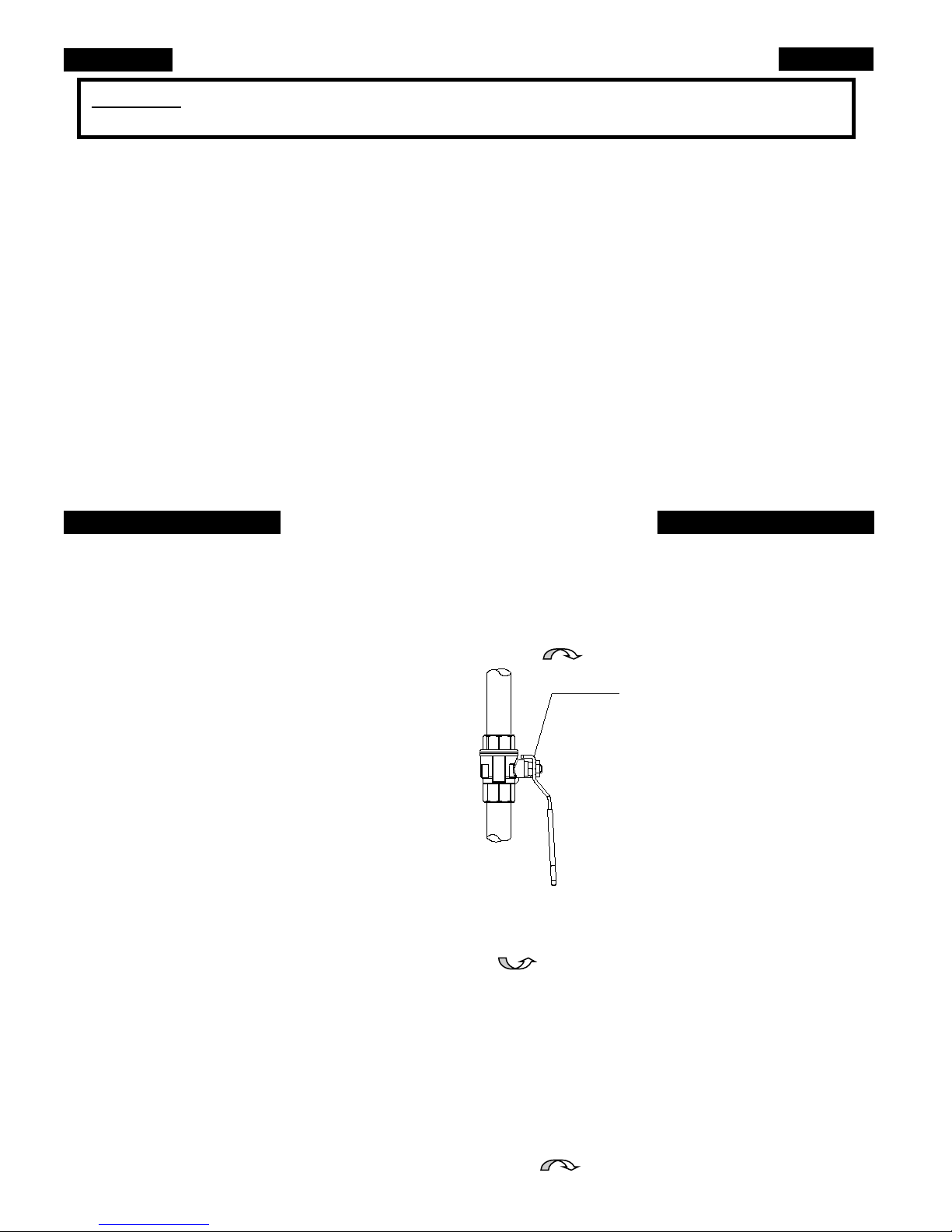
External manual
gas shutoff valve,
supplied by installer.
A typical ball valve is shown,
some models do not have a
handle, your installation may
vary.
lights the burner. DO NOT try to light the burner by hand.
floor because some gas is heavier than air and will settle on the floor. See below.
WHAT TO DO IF YOU SMELL GAS
• Do not try to light any appliance.
• Do not touch any electric switch; do not use any phone in your building
• Immediately call your gas supplier from a neighbor’s phone. Follow the gas supplier’s
instructions.
by hand, don’t try to repair it, call a qualified service technician. Force or attempted repair
technician to inspect the boiler and to replace any part of the control system and any gas
2. Set the thermostat(s) and aquastat(s) to their lowest setting.
3. Turn the service switch located on the front panel “OFF”.
4. This burner is equipped with an ignition device which autom atically lights the burner. Do not try
to light the burner by hand.
5. Turn the external manual gas valve ha ndle clockwise to the “CLOSED” position (valve
handle will be perpendicular to gas piping).
6. Wait five (5) minutes to clear out any gas. Then smell for gas, including near the floor. If you
smell gas, STOP! Follow the safety information above. If you don’t smell gas, go to the next
step.
7. Turn manual gas valve handle c ounterclockwise to the “OPE N ” posi t ion (valve handle
will be parallel to gas piping).
8. Set thermostat(s) to desired sett ing.
9. Turn on all electric power to the burner and boi ler.
10. If the burner/boiler will not operate, follow the inst r uctions “TO TURN OFF GAS TO THE
BURNER” below and call your service technician or gas suppl ier.
3. Turn the external manual gas valve handle clockwise to the “CLOSED” position.
Accel CS Boiler - Gas Heat - Eighth Edition – January, 2015 3
2. Turn the service switch on the Accel CS front panel “OFF”.

INSTALLER NAME:
INSTALLER ADDRESS:
INSTALLER CITY, STATE:
DATE INSTALLED:
NOTES:
RECORD OF INSTALLATION
All installations m ust be made in accordance with all State and Loc al Codes, which may differ from this manua l and in
accordance with the following Codes, as applicable:
National Fuel Gas Code, ANSI Z223.1/NFPA 54:
Installation Codes, CAN/CGA B149
National Electrical Code, ANSI/NFPA 70
Canadian Electrical Code Part I, CSA 22.1, Electrical Code
Chimneys, Fireplaces, Vents and Solid Fuel Burning Appliances, ANSI/NFPA 211
Where required by the authority having jurisdiction, the installation must conform to the Standard for:
ANSI/ASME CSD-1 Controls and Safety Devices for Automatically Fired Boilers
These codes are available from:
National Fire Protection Association
1 Batterymarch Park
Quincy, MA 02269-9101.
A hot water boiler installed above radiation level or as required by the Authority having jurisdiction, must be provided with a
low water cutoff device.
Make sure relief discharge pipes from all reliefs are properly placed to safely contain discharge. Make sure relief discharge
pipes, such as from a boiler or a hot water storage tank, will safely contain hot water and/or boiling water. Make sure relief
discharge pipes, such as from a boiler or a radiant heating system, will safely contain water treate d with bo iler chemicals
and/or antifreeze. Reliefs include the boiler pressure relief valve, the back flow preventer discharge port, and the domestic
hot water tank temperature and pressure relief valve. Any other reliefs, such as from radiant heating systems, must also
follow these guidelines.
Accel CS Boiler - Gas Heat - Eighth Edition – January, 2015 4
TABLE OF CONTENTS
Page
Topic
Page
Topic
1
Please Read This First
34
Boiler Water Treatment
4
Record of Installation
34
Winterizing
6
Accel CS Boiler
34
Wiring and Controls
Principle of Operation
Principle of Operation
7
Receiving and Unpacking
35
Hydronic Circulators
8
Clearance to Combustibles and Service
35
Low Voltage Wiring
8
Boiler Weight, Water Content
35
Installation with More than Five Zones
9
Boiler Dimensions
35
Condensing Energy Manager Operation
10
Venting and Combustion Air
37
Condensing Energy Manager Interface
10
Removal from Common Vent System
38
Condensing Energy Manager Option Switches
12
Length of Run, Intake and Vent
40
Hydronic Control Settings
13
Sidewall Vent Limitations
40
Auto Reset High Limit
14
Vent Outlet Location
40
Sola User Interface
15
Venting Materials And Venting Options
42
Prepare for Start Up
17
Venting with EK Sidewall Vent Kit
42
Start Up Procedure
18
Venting with PP, low profile
43
Air Free Method of Measuring CO
19
Venting with PP, snorkel style
44
Gas Valve Setup Procedure
20
Venting with PP, snorkel style below grade
46
Troubleshooting with the Energy Manager
21
Venting with PP, concentric hood
46
Operating Without an Energy Manager
22
Venting with PP, vertical through chase
47
Diagnostics with the Accel CS display
23
Hanging of Vent Piping
48
Lockouts, holds and alerts
24
Combustion Air
50
Flashing light on Manager
24
Condensate Drain Trap
50
Monitor light on the Manager
25
Gas Piping
50
Pump Exercise
26
Gas Pipe Sizing
50
Frost Protection
27
Gas Supply Pressure
51
Temperature Sensors
28
LPG Orifice
52
Drawings - Piping
29
Converting from one gas to another
58
Drawings – Wiring
29
Gas Valve Description
66
Annual Tune Up & Inspection
30
General Assembly
66
Burner head removal
30
Boiler Mounting
67
Top insulation replacement
30
Boiler Mounting on Boiler Base
67
Commercial Installation Kit
30
Wall Mounting The EK1C Boiler
68
Replacement Parts
31
Hydronic Piping
70
Exploded View of Boiler
Cover
Cover
33
Filling with Water, Venting and Purging
Accel CS Boiler
6
Condensing Energy Manager
7
34 Line Voltage – Electrical Connections
35 Surge Suppression
Inside
31 Zone Control
32 Domestic Hot Water
Accel CS Boiler - Gas Heat - Eighth Edition – January, 2015 5
Back
Back
Limited Lifetime Warranty
Warranty Transfer Agreement

Accel CS BOILER
IMPORTANT MESSAGE TO HOMEOWNER: These instructions should be carefully read and kept for future reference to
gain the best performance from your Accel CS boiler.
CONGRATULATIONS ON YOUR PURCHASE OF THE Accel CS BOILER with its highly efficient condensing low mass
hydronic heat exchanger, modulating burner and state of the art zone and domestic hot water control. It is the product of
years of engineering and advanced design, which brings together in a single system all elements needed to provide
efficient home heat. This operation and maintenance information has been prepared so that you may better understand
and use your Energy Kinetics Accel CS boiler and Heating System.
The Accel CS Boiler basically consists of a heat source (gas burner with control), an energy converter, piping, sheet
metal chassis and outer covers. For a typical residence, the installation may include a circulating water pump and up to five
zones controlled by the electronic Condensing Heat and Hot Water Hybrid Energy Recovery Control (Condensing Energy
Manager). For a typical multi-boiler light commercial situation, the installation may include a multi-boiler control along with
the appropriate primary/secondary piping. To support both types of installations, Energy Kinetics provides suggested piping
and wiring schematic drawings, which will be provided upon request. For any questions about installations not already
explained within this manual, consult Energy Kinetics Tech Support at 800-323-2066.
Accel CS BOILER - PRINCIPLE of OPERATION
The Boiler remains cold until a thermostat calls for heat. The Condensing Energy Manager receives the call for heat and
opens the respective heat or hot water zone, turns on the main circulator and burner. When the thermostats are satisfied,
the Condensing Energ y Manager turns off the burner and enters the energy recovery stage. The circulator and zone (zone
valve or zone circulator) stay energized to deliver the heat remaining in the boiler to your home.
When energy recovery is complete and the Boiler has cooled off, the Condensin g Energy Manager turns off the system
and waits for another thermostat (or tank thermostat) to call for heat. The Accel CS runs the burner onl y when you need
heat and delivers that heat only where you need heat.
The Accel CS Energy Converter is the product of advanced thermal engineering. It is designed with thirty seven fire
tubes, optimized to produce the maximum condensation with water side baffles to direct hydronic water flow and improve
heat transfer. This is a “forced circulation counter-flow” design that provides very efficient transfer of heat from the burning
fuel to the circulating water. The superior insulation of the boiler minimizes heat losses to the surroundings, resulting in
directing heat to your home in an efficient and quiet manner.
The Accel CS has an extremely high annual efficiency (over 99% of steady state) because it runs only when your home
needs heat. Energy recovery is completed at the end of each heat call, virtually eliminating off cycle losses.
Your Accel CS holds a small volume of water and it begins to supply heat very quickly. Maximizing condensing operation
by operating with lower boiler temperatures during war mer outdoor weather can cause longer and slower responses to
thermostat calls. The innovative SmartBoost™ function accelerates the response to recovery from thermostat night
setbacks for enhanced comfort and savings. Depending on the model, the Accel CS can heat water with input rates of up
to 399,000 BTU’s per hour.
The Accel CS boiler is designed with a removable burner flange and condensate collector that allows access to the inside
of the boiler for inspection and cleaning. All access for service is from the front, top, and bottom and the Accel CS boiler
may be floor mounted on a stand, or may be optionally mounted on a wall.
Accel CS Boiler - Gas Heat - Eighth Edition – January, 2015 6

CONDENSING ENERGY MANAGER - PRINCIPLE of OPERATION
The left side of the Co nde n s ing Energy Manager is the input side, which provides 24-volt power supply and connections
for thermostats. The right side is the output side, which powers the zone valves or zone circulators and signals the burner
and main circulator control.
Lights on the Condensing Energy Manager indicate what is calling for heat on left side and right side lights indicate active
zone(s), burner operation and Smart Pump and/or Injection zone operation. These function lights are an aid in servicing.
The following is a typical cycle.
1. SYSTEM WAITING FOR A CALL: There is not an active thermostat call, and the boiler is off and remains c old, waiti ng
until a call for heat. The red power light on the Condensing Ener g y Manager is glowing.
2. CALL FOR HEAT: A room thermostat call starts the cycle. The thermostat light on the left side will turn on for that zone.
3. HEAT: Output lights for the zone output and heat demand turn on, the main circulator starts, the zone opens and the
burner begins its firing cycle with pre-purge followed b y igniti on. The boiler water circulates through the boiler and the
active zone, heating up the water and the connected radiation. The controls include the option for outdoor reset and will
set the boiler supply temperature as needed based on the outdoor temperature and the outdoor reset settings.
4. HOT WATER CALL: A hot water call is similar to a heat call, except hot water is most effectively and efficiently
produced and delivered when the boiler supply temperature is between 165ºF and 180ºF. For this reason, upon a call
for domestic hot water, the supply set point temperature of the Accel CS boiler is increased to 182ºF. The boiler will
heat up the boiler side of the plate heat exchanger. Once the boiler supply temperature has reached 140ºF, the
domestic hot water circulator is turned on. With domestic water pumping through the domestic side of the plate heat
exchanger and boiler water pumping through the boiler side of the plate heat exchanger, the water in the storage tank
will be heated quickly and efficiently. The temperature of the domestic water coming out of the plate heat exchanger is
determined by the flow rate of the domestic water. Partially close the ball valve below the smart pump to reduce the flow
and increase the temperature, or partially open the ball valve below the smart pump to increase the flow and decrease
the temperature. The plate heat exchanger is so effective at heat transfer that this operating temperature still allows a
high level of condensation of the flue gas for peak efficiency. Note that this is much more effective than a tank with an
internal coil during heating and in the Energy Recovery Cycle. The burner runs as long as there is a thermostat calling
and as long as heat is being delivered to the zone. Hot water priority is always active during a hot water call, so the
heating zone outputs will be turned off for the duration of the hot water call or up to 25 minutes, which ever comes first.
5. THERMOSTAT SATISFIED: The thermostat light on the left side will go out. The burner will then turn off.
6. ENERGY RECOVERY: The circulator and zone valve remain energized. The circulating water will remove the energy
from the boiler, sending the heat to the last zone that called. The energy recovery stage continues until the boiler
temperature has dropped sufficiently or until maximum timing has been reached. The boiler is now sitting cold, waiting
for the next call for heat. Maximum timing for heat recovery stage is twenty minutes for space heating zones and is five
minutes for the hot water zone. Zone four has the option to shorten maximum heat recovery timing to five minutes.
RECEIVING and UNPACKING
Inspect shipment upon receipt for external damage. Further inspect any items that appear damaged by opening shipping
packaging before signing for the freight. Refuse any individual shipping cartons or packages that are damaged or appear to
be damaged. Contact Energy Kinetics and freight carrier.
After unpacking, check each item against the packing list. Inspect it thoroughly for loose parts, instruction sheets and
packing lists. Immediately report any missing items. It is wise to complete the installation before discarding packing
material. Store all parts where they will not be damaged or lost during installation. Any claims for damage or shortage in
shipment must be filed immediately against the transportation company by the consignee.
Accel CS Boiler - Gas Heat - Eighth Edition – January, 2015 7

CLEARANCE to COMBUSTIBLES and SERVICE
Installation Clearances from Boiler Surfaces, Inches
Clearance to Combustibles
Clearance for Service
Front of boiler
0 inches
20 inches
Left side of boiler body
0 inches
0 inches
Right side of boiler body
0 inches
0 inches
Back of boiler body
0 inches
1 inch
Top of boiler body
0 inches
20 inches
Bottom of boiler chassis to floor (Without boiler base)
0 inches
12 inches*
Stainless Steel Class III Vent Pipe (Z-Flex Z-Vent III)
Refer to Manufacturer Specs.
Refer to Manufacturer Specs.
Polypropylene (Centrotherm & DuraVent)
Refer to Manufacturer Specs.
Refer to Manufacturer Specs.
PVC and CPVC Ven t Pip e
Not Recommended
Not Recommended
Boiler Weight and Water Content
Model
Weight, dry
Weight, filled with
water and w/stand
Water Content
In Gallons
Supply and
Return Pipe Size
Air Inlet Pipe Size
In Inches
Boiler Flue Outlet
In Inches
EK1C
197 lbs
267 lbs
5
1” NPT
3”
3”
EK2C
275 lbs
377 lbs
6-1/2
1-1/4” NPT
4”
4”
EK3C
360 lbs
512 lbs
12
1-1/2” NPT
4”
4”
"W"
SUPPLY
"D"
"A"
"B"
EK1C FLUE CONNECTOR
EK1C AIR INLET
EK2C & EK3C FLUE
CONNECTOR
EK2C & EK3C AIR INLET
Due to the low stack temperature of the condensing boiler, the Accel CS boile r may be installed with zero clearance to
combustibles. Specifically, with zero clearance to top, bottom, left, right, front and back.
DANGER: Provide clearance to combustible surfaces in accordance with all local and national codes. Follow National Fire
Protection Association Bulletin NFPA Installation of Gas Burning Equipment and all applicable codes.
NOTICE: Do not install on c arpeting. Place th e unit as near to the vent as possible allowi ng clearance for c leaning and
service. If not using an Energy Kinetics supplied stand or wall mounting brackets, provide a solid, level, smooth
foundation with cleara nce for opening covers for service and enough s pace under the unit f or the condensate
trap.
NOTICE:
When determining boiler location, consider hydronic piping, venting, air intake and wiring.
*Minimum recommended clearance to allow a condensate trap/neutralizer/pump.
Figure 1A - Boiler Dimensions - Top View
Accel CS Boiler - Gas Heat - Eighth Edition – January, 2015 8
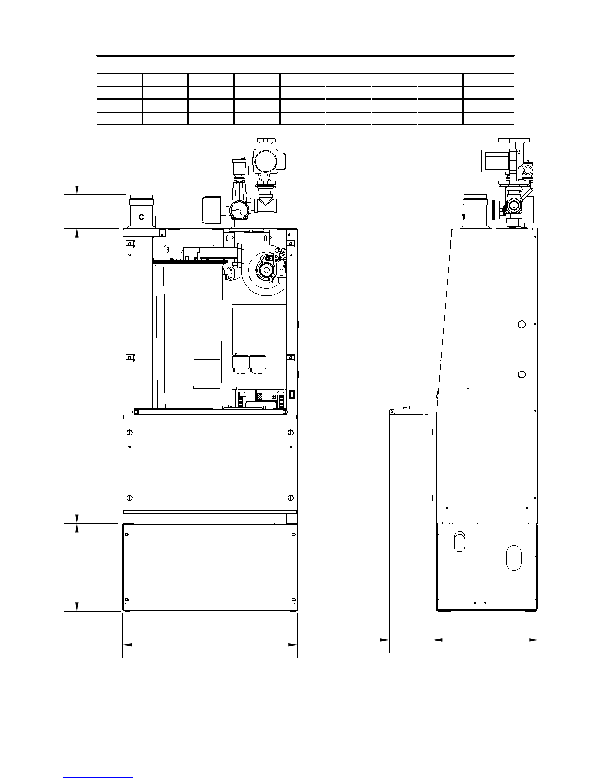
DIMENSIONS
Model
“H”
“HT”
“HB”
“W”
“D”
“D2”
“A”
“B”
EK1C
40-5/8”
4-5/8”
12”
25-7/8”
15”
10”
3-7/8”
4-13/16”
EK2C
45-3/8”
6-1/2”
12”
28-1/8”
18-1/2”
10”
5-1/8”
6-1/2”
EK3C
47-1/4”
5-1/2”
12”
32”
22-3/8”
10”
4-5/8”
10”
"W"
"HB"
"H"
"HT"
"D2"
"D"
Figure 1B - Boiler Dimensions - Front and Side Views
Accel CS Boiler - Gas Heat - Eighth Edition – January, 2015 9

Model Firing Rate Range
Max In
(BTUs)
Min In
(BTUs)
Max Out
(BTUs)
Min Out
(BTUs)
EK1C
Standard 120,000 24,000 114,000 22,800
“Smart” Rate 90,000 18,000 85,500 17,100
Standard 200,000 40,000 190,000 38,000
EK2C
“Smart” Rate 150,000 30,000 142,500 28,500
Standard 399,000 79,800 379,050 75,810
EK3C
“Smart” Rate 300,000 60,000 285,000 57,000
VENTING AND COMBUSTION AIR
Overview
The Accel CS boiler is a direct vented condensing boiler. Venting of the burnt flue gases requires approved flue piping
listed herein. Fresh air for combustion must be supplied to the boiler from outdoors using approved intake piping listed
below. The boiler cabinet doors must be in place and tightened during normal operation. When venting through the side of
a building, fresh air intake and flue gas venting must enter and exit on the same side of the building. When venting through
a chimney (where the chimney is used as a chase for a liner rated for positive pressure condensing operation), fresh air can
be piped alongside the liner inside the chimney chase or fresh air can also be taken from the basement.
The Accel CS boiler can be vented using the Energy Kinetics stainless steel sidewall vent system using Z-Vent III
stainless steel piping for the vent connections. The Energy Kinetics stainless steel sidewall vent system has been used for
many years to vent the System 2000 family of boilers and has a proven track record of operation.
The Accel CS boiler can also be vented using approved polypropylene venting systems such as manufactured by
Centrotherm and by DuraVent. The Accel CS boiler may not be vented usin g PVC , CPVC, or ABS piping.
BEST PRACTICE: Pipe the combustion Air Inlet directly to the outdoors, even if venting vertically through a liner inside a
chimney chase to avoid any of the contaminations often found in indoor air and to improve overall
efficiency of operation.
The installation of the flue vent and combustion air piping must comply with local codes and requirements and with the
National Fuel Gas Code NFPA 54, ANSI Z223.1 for installations in the USA or with CSA B149.1 or B149.2 for installations
in Canada
NOTICE: The Accel CS boiler requires a special venting system designed for pressurized venting rated ANSI Z21.13
Category 4. As such, the flue gas will condense in the flue and provision must be made to accommodate this.
DANGER: All flue piping must be tightly sealed as per the pipe manuf ac tur er’s recom mendation to insure against leakag e
WARNING: Sidewall venting (direct vent) requires outside air to be piped directly to the boiler.
WARNING: No solid fuel appliance or fireplace should be installed in a flue common with this heating appliance.
of noxious fumes, deadly carbon monoxide and/or condensate water.
WARNING: You may use any of the vent and air piping options covered in this manual. Do not use any other method or
WARNING: Do not insulate the plastic flue pipes as excessive sagging of the plastic sections could result.
material when installing this appliance.
REMOVAL FROM COMMON VENT SYSTEM
DANGER: When any existing appliance, such as a boiler, is removed from a common venting system, the common
venting system is likely to be too large for proper venting of the appliances remaining connected to it. Testing
of the remaining venting system must be performed according to the following procedure.
At the time of removal of the existing appliance, the following steps shall be followed with each appliance remaining
connected to the common venting system placed in operation, while the other appliances remaining connected to the
common venting system are not in operation.
1. Seal any unused openings in the common venting system.
2. Visually inspect the venting system for proper size and horizontal pitch and determine there is no blockage or
restriction, leakage, corrosion and other deficiencies which could cause an unsafe condition.
3. Insofar as is practical, clos e all building doors and windows , and all doors between the space in w hich the appliances
remaining connected t o the common venting system are loc ated and other spaces of the building . Turn on clothes
dryers and any appliance not c onnected to the common venting system. T urn on any exhaust fans, suc h as range
Accel CS Boiler - Gas Heat - Eighth Edition – January, 2015 10

hoods and bathroom ex hausts, so the y will operate at m aximum speed. Do not operate a s umm er exhaust fan. C lose
fireplace dampers.
4. Place in operation th e appliance be ing inspected. F ollow the light ing instructions . Adjust ther mostat so applia nce will
operate continuously.
5. Test for spillage after five minutes of main burner operation. Use a draft gauge or pressure gauge to verify that the vent
pipe at the breech of the appliance is under draft (negative pressure) relative to the room.
6. Repeat steps 4 and 5 for each appliance connected to the common venting system, one appliance at a time.
7. After it has been determined that e ach appliance remaining connec ted to the common venting system properly vents
when tested as outlined above, return doors, windows, exhaust fans, fireplace dampers and any other gas-burning
appliance to their previous condition of use.
8. Any improper operation of the comm on venting system should be cor rected so the installation conf orm s to the National
Fuel Gas Code, ANSI Z2 23.1/NFPA 54 and/or CAN/ CGA B149 Installat ion Codes. When resizing an y portion of the
common venting s ystem, the comm on venting s ystem should be r esized to app roach the m inimum size as determined
using the appropriate ta bles in Part 11 of the National Fuel Gas Code, ANSI Z223.1/NF PA 54 and/or CAN/CGA B149,
Installation Codes.
Accel CS Boiler - Gas Heat - Eighth Edition – January, 2015 11
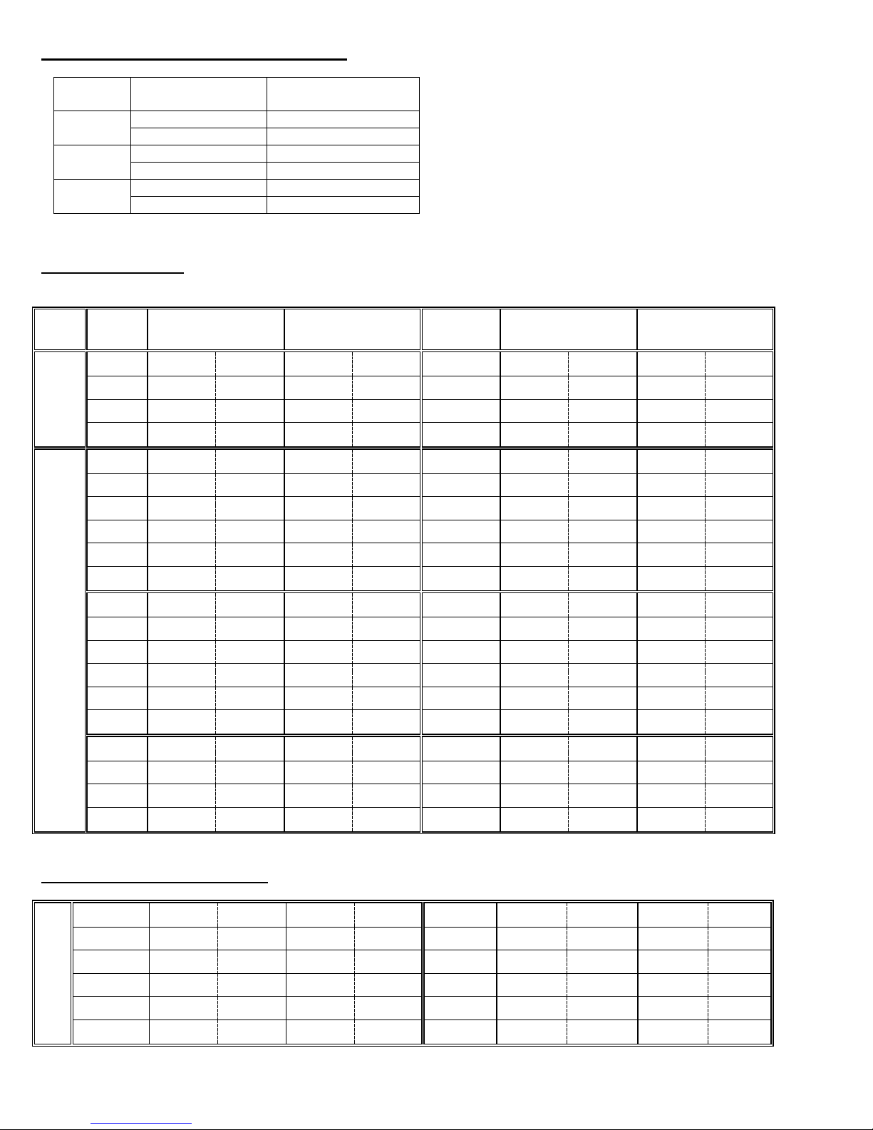
LENGTH OF RUN, INTAKE AND VENT
Vent
Size
Natural
Gas
EK1C
Low
High
Low
High
EK1C
Low
High
Low
High
15'
1400
6000
1200
4600
15'
1500
6200
1300
4800
25'
1500
6200
1200
4800
25'
1600
6400
1300
5000
50'
1600
6500
1200
5000
50'
1600
6700
1300
5200
EK1C
Low
High
Low
High
EK1C
Low
High
Low
High
15'
1300
5900
1200
5600
15'
1300
6200
1200
5900
25'
1300
6000
1200
5700
25'
1300
6200
1200
5900
50'
1400
6100
1300
5800
50'
1300
6300
1300
6000
75'
1400
6100
1300
5900
75'
1400
6400
1300
6100
100'
1500
6200
1400
6000
100'
1400
6400
1300
6100
EK2C
Low
High
Low
High
EK2C
Low
High
Low
High
15'
1200
5100
1000
4100
15'
1300
5600
1100
4300
25'
1200
5300
1000
4200
25'
1300
5700
1100
4400
50'
1300
5500
1100
4300
50'
1300
5800
1100
4500
75'
1400
5700
1100
4400
75'
1400
5900
1200
4600
100'
1400
5800
1100
4500
100'
1400
6000
1200
4700
EK3C
Low
High
Low
High
EK3C
Low
High
Low
High
15'
1400
6700
1200
5400
15'
1600
7200
1300
5600
25'
1500
7000
1200
5800
25'
1600
7500
1300
5900
50'
1600
7800
1200
6200
50'
1700
7800
1300
6400
EK3C
Low
High
Low
High
EK3C
Low
High
Low
High
15'
1500
7100
1200
5400
15'
1500
7300
1200
5600
25'
1500
7100
1200
5400
25'
1500
7400
1200
5700
50'
1500
7200
1200
5500
50'
1600
7600
1200
5800
75'
1600
7200
1200
5500
75'
1600
7800
1300
5900
100'
1600
7300
1300
5600
100'
1600
7800
1300
6000
Inlet & Outlet
Pipe Size
2”
50 Feet
3”
100 Feet
3”
50 Feet
4”
100 Feet
3”
50 Feet
4”
100 Feet
Model
EK1C
EK2C
EK3C
Fan Speed Set Guide:
Use the following chart to select the optimal fan speed range based on your venting parameters.
Maximum Length*
*Air Inlet and Vent Pipe:
Subtract 5 feet from the maximum length for each
elbow added. A total equivalent length of 50 feet is
allowed. For example, if (5) ninety degree elbows are
used, subtract 5 x 5 ft = 25 feet from the maximum of
50 equivalent feet, for a maximum of 50 ft – 25 ft =25
feet of straight pipe allowed.
LPG Standard RPMs Alternate RPMs
Standard RPMs Alternate RPMs
2”
Venting
3” Venting
Fan Speed Set Guide (Continued)
4” Venting
Accel CS Boiler - Gas Heat - Eighth Edition – January, 2015 12

Vent Pipe Joint Connections
WARNING: Joint connections not meeting full insertion can leak, causing severe personal injury, death or substantial
property damage.
DANGER: Fasteners (screws, rivets, etc.) must not penetrate the components of the vent system either when joining
pipes and fittings or using support straps. Drilling holes in the components is not permitted. Exception: For
exterior components onl y, one stainless steel screw per joint may be used to fix direction of vent.
CAUTION: Damaged gaskets can cause leakage of dangerous levels of carbon monoxide or property damage due to
condensate leaks.
Each female end of each component uses a gasket installed by the vent manufacturer. Check each
component to ensure the gasket is present and not damaged from shipping.
Stainless Steel: Pipe insertion at joint must be at least 1.75” minimum
Gear clamps must be tightened to a minimum of 40 in/lbs with a maximum of 50 in/lbs.
WARNING: Over tightening the gear clamp can cause the seal to fail. DO NOT use power tools when tightening gear
clamps.
Polypropylene: Locking rings must be used at each interior connection to meet the requirements of ULC-S636 & UL-1738.
SIDEWALL VENT LIMITATIONS
The Accel CS boiler and the vent system must be carefully installed, adjusted and maintained. It should be annually
checked and adjusted if necessary.
The conventional chimney can absorb, unseen, the many things that can go wrong with a combustion system such as
poor ignition, improper air adjustment, accumulation of pet hair or lint on the inlet shutter, component malfunctions,
improper setup or installation, etc.
With sidewall venting, the eff ect of these conditi ons ca n result in an ex haust that may contain odors or incompletely
burned fuel. These flue products, while still effectively discharged outside the home, may cause discoloration to siding or
areas immediately surrounding the vent. The flue by-products may be corrosive and can cause damage to nearby objects
such as condensers, playground equipment, landscaping, shrubs, etc. The exhaust may emit odors similar to a poorly
tuned car exhaust. This would normall y not be appare nt when dis char ge d fr om a chimney well above the roofline.
No one can guarantee that at all times the exhaust will be without a trace of odor or corrosive by-products for all the
reasons described above which may be beyond the control of the homeowner, manufacturer, installer or service company.
Periodic cleaning of the area around the vent may be required if the appearance is objectionable in the vie w of the
homeowner. This cannot be the responsibility of the manufacturer, installer or service company.
Accel CS Boiler - Gas Heat - Eighth Edition – January, 2015 13
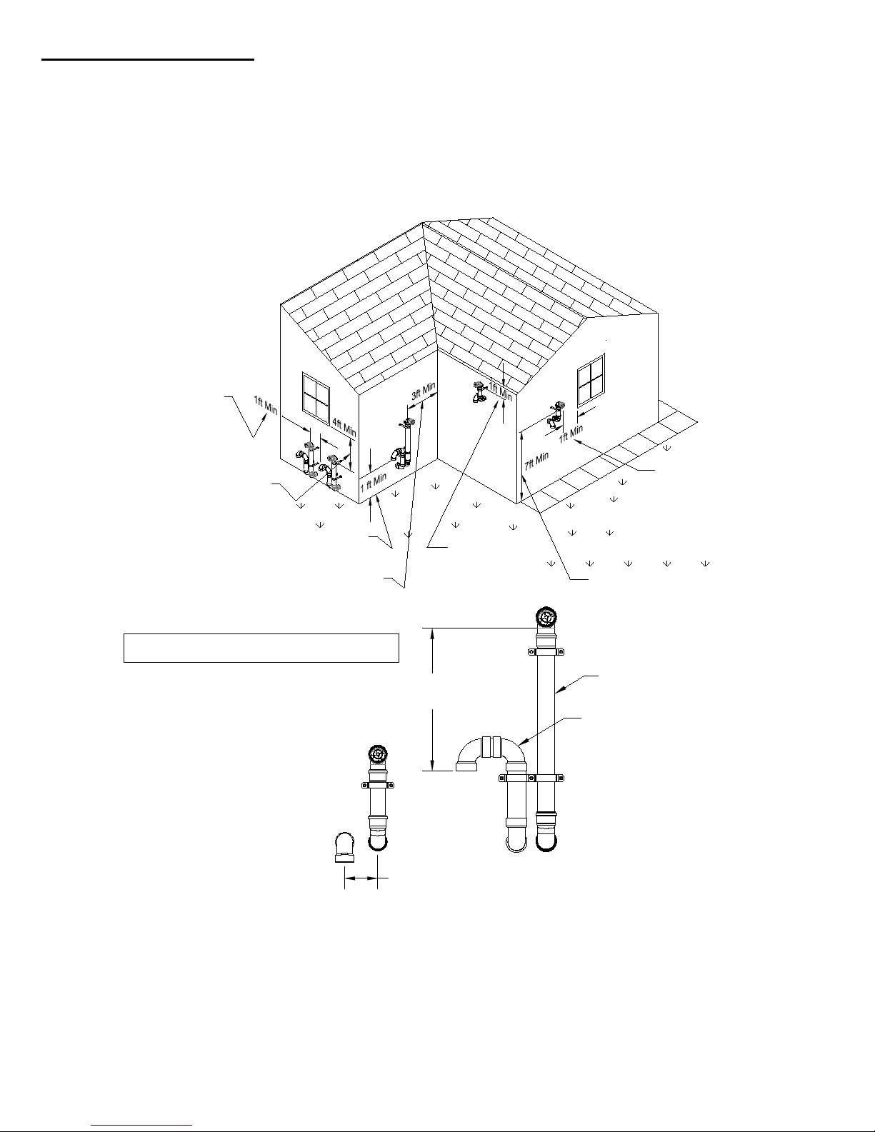
VENT OUTLET LOCATION
Vent must be at least 1 ft.
from any doors or
windows. (Energy Kinetics
recommends 4 ft minimum
whenever possible)
Vent must be at least 3 ft.
from inside corners.
Recommend 10 ft.
Air in-let must be at least 1 ft. above anticipated snow
level. (Energy Kinetics recommends 2ft minimum
whenever possible).
Vent must be at least 4 ft.
below windows (though not
recommended)
Vent must be at least 7 ft. above
public walkways
SIDEWALL VENT/INLET TERMINATION
LOCATION REQUIREMENTS
Vent termination must be at least 3ft above any
forced air intakes within 10 feet.
Vent must be at
least 1 ft. below
the soffit of roof of
the structure.
Multiple boiler Vent/Inlet
terminations must have
1ft min clearance
between edge of inlet
opening and adjacent
termination
12"-15"
Above Air Inlet
Vent Must Be PPS
Air Inlet May Be Piped
with PPS or PVC
4" Min Horizontal Separation
The hood or exhaust pipe should be located so that proper clearances are maintained, according to local code. Per the
National Fuel Gas Code NFPA 54 ANSI Z223.1, the flue gas outlet termination of a direct vent application with an input
over 50,000 Btu/hr shall be located at least 1 ft from any door, window, or air inlet to the structure.
Note that the Accel CS boiler meets the definition of a direct vent appliance as used in NFPA 31 & NFPA 54.
Regardless of input, the flue gas outlet terminal and air intake shall be located at least 1 ft. above grade or at least 1 ft.
above expected snow level, whichever is higher. Although not requ ir ed, En erg y Ki netics recom mends at least 2 ft.
above grade whenever possible. Both the vent hood and air intake must be at least 5 ft. from any supply tank vents.
The vent terminal shall not be installed closer than 3 ft. from an inside corner of an L-shaped structure and must
be at least 1 ft. from the soffit of the roof of the structure.
Accel CS Boiler - Gas Heat - Eighth Edition – January, 2015 14
VENTING MATERIALS AND OPTIONS
Where to obtain venting materials
Manufacturer
Material
Product
Telephone
Web Address
Energy Kinetics EK1 or EK 2
sidewall vent kit
Z-Flex
Stainless steel
Z-Vent III, 2”, 3” or 4”
800-654-5600
www.novaflex.com
Centrotherm
Polypropylene
Innoflue, 2”, 3” or 4”
877-434-3432
www.centrotherm.us.com
DuraVent
Polypropylene
PolyPro, 2”, 3”, or 4”
800-835-4429
www.duravent.com
Venting material must be Listed by a nationally recognized testing agency.
Manufacturer
Material
Agency
Minimum Thickness
Energy Kinetics
Stainless steel
UL
0.020”
Z-Flex
Stainless steel
UL
0.020”
Centrotherm
Polypropylene
ETL
0.020”
DuraVent
Polypropylene
ETL
0.020”
Approved Vent and Air Inlet Pipe Mater ial
Item
Material
Standards
Stainless Steel (AL29-4C)
UL-1738
UL-1738
ULC-S636
Stainless Steel (AL29-4C)
UL-1738
UL-1738
ULC-S636
PVC Schedule 402
ANSI/ASTM D1785
UL-1738
ULC-S636
CPVC Schedule 402
ASTM F441
ABS Schedule 402
ASTM F628
Notes:
2. Use of PVC, CPVC, or ABS is only allowed for Air Inlet piping
The Accel CS Boiler can generate exiting flue gas temperatures between room temperature and 230oF, depending on
the modulated firing rate and the boiler water temperature. The Accel CS boiler can be safely vented using a variety of
venting materials. Approved materials include stainless steel, such as 316, 316L, 316Ti or AL 29-4C. Plastic venting
products made from polypropylene are approved. Plastic venting products made from other plastics, such as PVC, CPVC,
or ABS are not approved. Any of the plastic pipe materials may be safely used for air intake piping, but not for venting.
The venting materials for the Accel CS boiler may be obtained from Energy Kinetics, from Z-Flex, from Centrotherm or
from DuraVent. The Z-Flex, Centrotherm and DuraVent products may also be obtained from any stocking distributor that
carries these products.
Energy Kinetics Stainless steel
Appliance Adapter1
Vent Pipe & Fittings1
Air Inlet Pipe & Fittings
Polypropylene
Polypropylene (PPs)
Polypropylene (PPs)
800-323-2066 www.EnergyKinetics.com
1. Only Stainless Steel and Polypropylene material permitted for Venting
The Accel CS boiler may be vented using several different options, materials, and methods.
1) Energy Kinetics EK1 or EK2 sidewall vent kit using 3” Z-Vent III piping.
2) Sidewall venting using Polypropylene in 2”, 3” or 4” diameters.
a) Two pipe with low profile termination (2” & 3” only).
b) Two pipe with snorkel termination.
c) Concentric through the wall (2/4”, 3/5” or 4/6”).
3) Vertically with Polypropylene in 2”, 3” or 4” diameters.
a) Using a chimney as a chase.
WARNING: Sidewall vent systems must have outside air connected to the boiler and both intake and vent hood must be
located on the same side of the structure. Vertically vented systems should have outside air connected to the boiler.
The Accel CS boilers have a flue collar made of Z-Vent III AL29-4C stainless steel - 3” on the EK1C / 4” on the EK2C &
EK3C. If the boiler is vented using Z-Vent III stainless steel vent materials, then the venting may be directly connected to
the flue outlet. If the boiler is vented using either of the two polypropylene materials, then a stainless steel to polypropylene
appliance adapter is required. The fresh air inlet pip e si ze at the boiler is 3” on th e EK1C / 4” on the EK2C & EK3C. PVC
pipe may be used for air inlet only. When using one of the approved polypropylene terminations, it may be necessary to
adapt from PVC to polypropylene using the appropriately sized PVC to polypropylene adapter.
Accel CS Boiler - Gas Heat - Eighth Edition – January, 2015 15
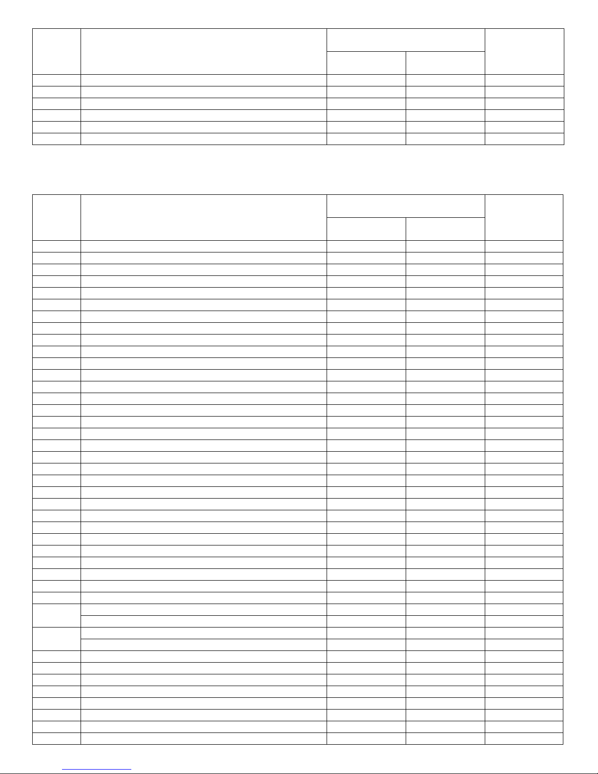
Item Description
Energy Kinetics stocks and sells
Centrotherm PPs Vent Items
Energy Kinetics
Part No.
Centrotherm
Part No.
1
3” Appliance adapter, stainless to PPs
10-1000
ISSA0303
N/A 1 3” Appliance adapter, stainless to PPs
10-0194
N/A
N/A 2 2” Intake adapter, PVC to PPs
10-1023
ISAGL0202
2PPS-AD
3
3” Intake adapter, PVC to PPs
10-1013
ISAGL0303
3PPS-AD
4
4” Intake adapter, PVC to PPs
10-1024
ISAGL0404
4PPS-AD
5
5” Intake adapter, PVC to PPs
10-1025
ISAGL0505
5PPS-AD
Energy Kinetics stocks and sells
Centrotherm PPS Vent Items
Energy Kinetics
Part No.
Centrotherm
Part No.
4
2” Locking ring, typical
10-1017
IANS02
2PPS-LB
5
2” Wall mount brackets
10-1020
IASC02
2PPS-WSM
6
2” Bird screen
10-1022
IASPP02
2PPS-BG
7
2” PPs elbow, 45º
10-1021
ISELL0245
2PPS-E45
8
2” PPs elbow, 87/90º, long radius, bl ac k
10-1016-B
ISELL0287UV
2PPS-E90B
9
2” PPs elbow, 87/90º, long, gray
10-1016
ISELL0287
2PPS-E90
10
2” PPs pipe, 2 ft long, black
10-1015-24B
ISVL022UV
N/A
11
2” PPs pipe, 3 ft long, black
N/A
N/A
2PPS-36B
12
2” PPs pipe, 3 ft long, gray
10-1015-36
ISVL023
2PPS-36
13
2” Low profile wall mount termination
10-1029
ISLPT0202
N/A
14
3” Locking ring, typical
10-1010
IANS03
3PPS-LB
15
3” Wall mount brackets
10-1009
IASC03
3PPS-WSM
16
3” Bird Screen
10-1007
IASPP03
3PPS-BG
17
3” PPs elbow, 45º, black
10-1006
ISELL0345UV
3PPS-E45B
17
3” PPs elbow, 45º, gray
10-1001
ISELL0345
3PPS-E45
18
3” PPs elbow, 87/90º, lo ng r adius, bl ac k
10-1008
ISELL0387UV
3PPS-E90B
19
3” PPs elbow, 87/90º, long, gray
10-1003
ISELL0387
3PPS-E90
20
3” PPs pipe, 2 ft long, black
10-1004
ISVL032UV
N/A
21
3” PPs pipe, 3 ft long, black
N/A
N/A
3PPS-36B
22
3” PPs pipe, 3 ft long, gray
10-1002-36
ISVL033
3PPS-36
23
3” to 2” PPs Reducer
10-1019
ISRD0302
3PPS-R2
24
3” Low Profile Wall Mount Termination
10-1012
ISLPT0303
3PPS-HTP
25
3” Side Wall Vent Termination, EK Style Nozzle
ISEK03
N/A
26
3” ICTC adapter for Centrotherm
N/A
ICTC335
N/A
27
3”/5” Elbow, 45º
N/A
ICEL3545
N/A
28
3”/5” Elbow, 87º
N/A
ICEL3587
N/A
29
3”/5” Concentric pipe, 1 ft long
N/A
ICVLAL351
N/A
30
3”/5” Concentric pipe, 2 ft long
N/A
ICVLAL352
N/A
31
3”/5” Concentric pipe, 3 ft long
N/A
ICVLAL353
N/A
32
3”/5” Concentric wall termination, 5” OD
N/A
ICWT352
3PPS-HK
33
Joint lube, Centrocerin for Centrotherm
10-1011
IACE50
N/A
34
2” Wall plate, round rubber, black
10-1032
IAWP02B
N/A
2” Wall plate, square metal, black
N/A
N/A
2PPS-WPB
35
3” Wall plate, round rubber, black
10-1008
IAWP03B
N/A
3” Wall plate, square metal, black
N/A
N/A
3PPS-WPB
36
2” Horizontal Drain Tee
10-1026
ISHDT02
37
3” Horizontal Drain Tee
10-1027
ISHDT03
38
3” Test Port
10-1028
ISTP03
3PPS-TP
39
2” X 35 ft Flex Vent Length
10-1030
IFCK0235
3PPS-FLEX35
40
2” Coupler, Solid wall to Flex
10-1033
IFS02
2PPS-FAM
50
2” X 35 ft Flex Chimney Kit
10-1030
IFCK0235
N/A
51
3” X 35 ft Flex Chimney Kit
10-1014
IFCK0335
N/A
52
4” X 35 ft Flex Chimney Kit
10-1048
IFCK0435
N/A
DuraVent Part
No.
There are several parts that are used for all arrangements such as the locking rings needed for each joint, elbows,
straight runs of pipe, etc. These common parts are listed here and will not be listed on any of the following arrangements.
Typical venting parts. Order additional venting parts as needed for the job.
Item Description
DuraVent
Part No.
Accel CS Boiler - Gas Heat - Eighth Edition – January, 2015 16
53
4” Locking ring, typical
10-1041
IANS04
54
4” Wall mount brackets
10-1045
IASC04
55
4” Bird screen
10-1044
IASSS04
56
4” PPs elbow, 45º, black
10-1042
ISEL0445UV
57
4” PPs elbow, 45º, grey
10-1043
ISEL445
58
4” PPs elbow, 87/90º, long radius, black
10-1049
ISEL0487UV
59
4” PPs elbow, 87/90º, long, gray
10-1039
ISEL0487
60
4” PPs pipe, 2 ft long, black
10-1040
ISVL042UV
61
4” PPs pipe, 3 ft long, gray
10-1038
ISVL043
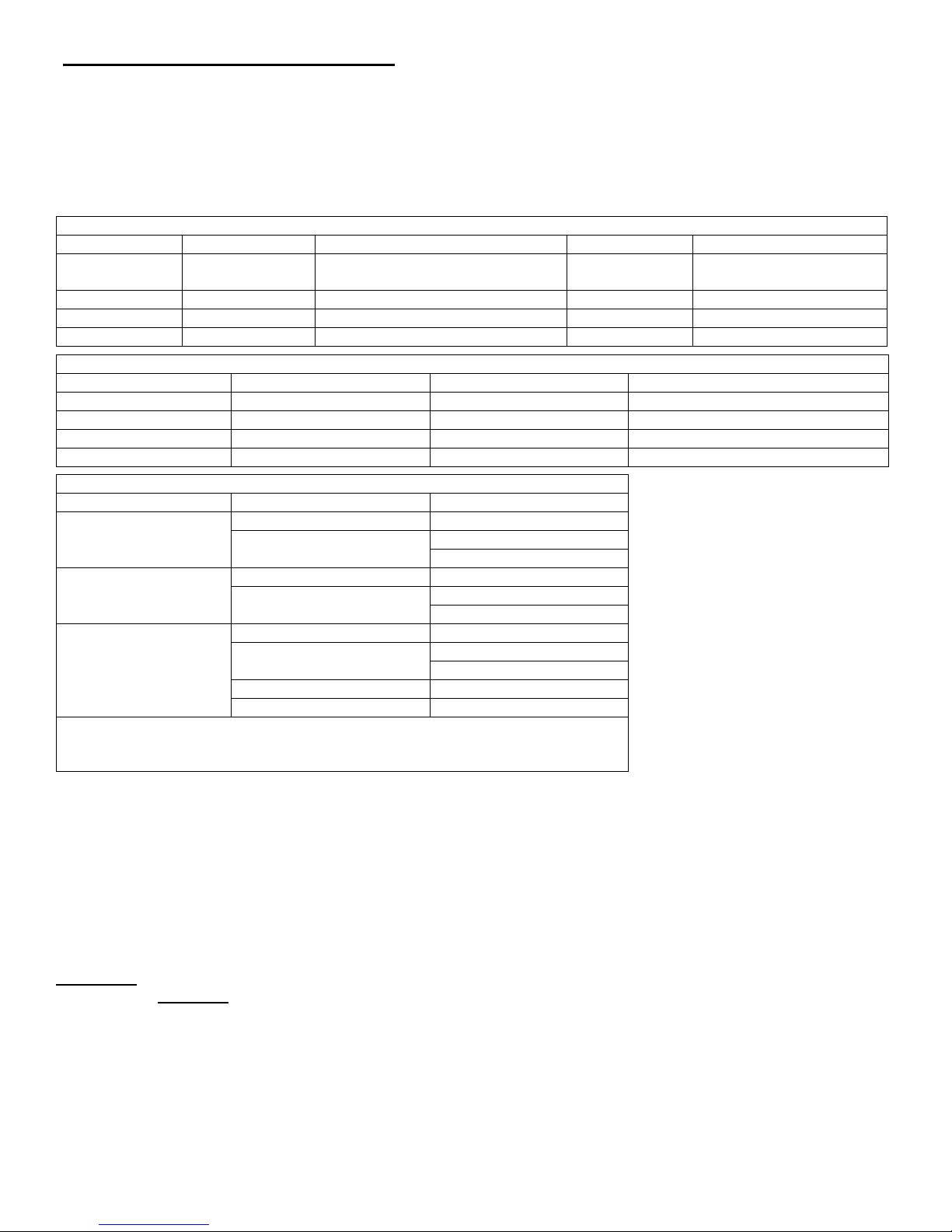
Item
Energy
No.
41
Combo Vent Hood (Includes: hood, trim ring, silicone sealant, mtg hardware, elbow & shield)
10-0332-1*
42
Non-Combo Hood (Includes: hood, trim ring, silicone sealant, mtg hardware, elbow & shield)
10-0333-1**
43
Extra Pipe 3ft Length
10-0191-P33
44
Extra Pipe 1ft Length
10-0191-P31
45
Extra 90 degree Elbow
10-0191-E390
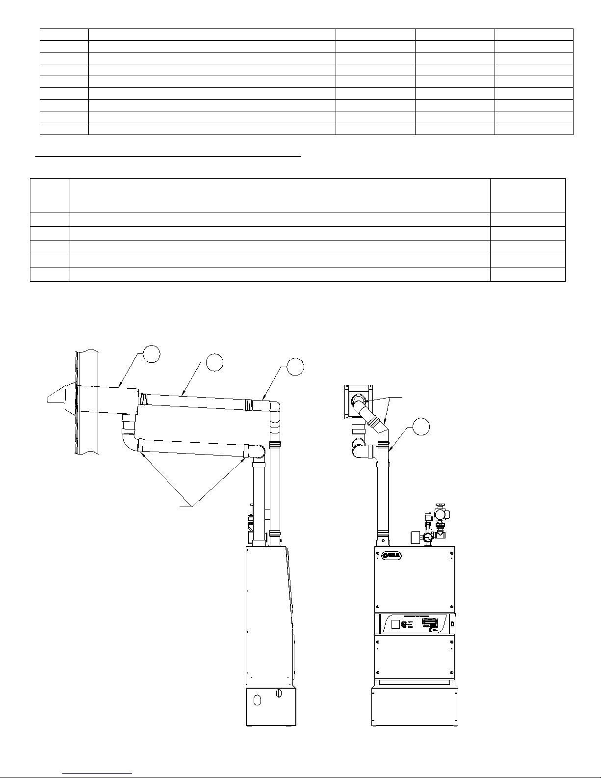
Use Swing Joint(s) to Attain Pitch
on Horizontal Run(s)
Inlet Piping Supplied by Installer
When using PVC Air Inlet Piping,
Fix Each Joint with a Stainless Steel
Screw or Glue with PVC Cement
43
45
41
41
Stainless Steel, Gasketed,
Positive Pressure Vent Piping.
Kit Includes:
(1) Sealed 3" Elbow
(3) Lengths of 3" x 3' Pipe
Order extra Pipe and Elbows as needed
VENTING WITH ENERGY KINETICS SIDEWALL VENT KIT
3” Stainless Steel Vent Kit and Optional Parts
Description
Kinetics Part
*Kit includes: Sidewall Vent Hood, (1) 90 deg. Elbow & Shield, (1) Trim Plate, (4) SS Mounting Screws & Inserts, (1) Tube
Silicone Sealant.
**Replaces Combination Vent Hood with Non-Combo, Vent Only Hood
Accel CS Boiler - Gas Heat - Eighth Edition – January, 2015 17
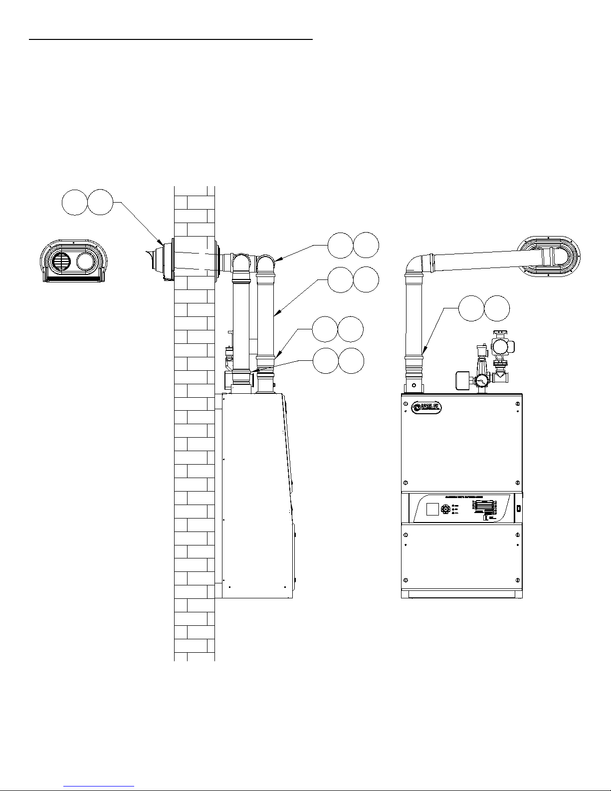
SIDEWALL VENTING WITH POLYPROPYLENE – Low Profile
24
1
3
12
9
13
19
22
23
23
4*
14*
* Locking rings must be used
on each joint located indoors
2” or 3” Low Profile Wall Mount Termination.
Part No: Description:
10-0584 Low Profile Vent Kit 2in PPs
10-0585 Low Profile Vent Kit 3in PPs
Low Profile Parallel Wall Termination incorporates air intake and exhaust into a single aesthetically pleasing
termination. Part is paintable to match exterior of structure. Interior wall plate and bird screen included. Exterior exhaust
can be extended or re-directed with PPS-UV black elbows or vent lengths. External joints may be fastened with stainless
steel screws. Vent lengths and elbows sold separately.
Accel CS Boiler - Gas Heat - Eighth Edition – January, 2015 18
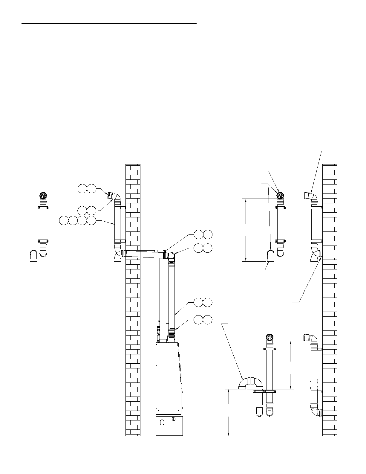
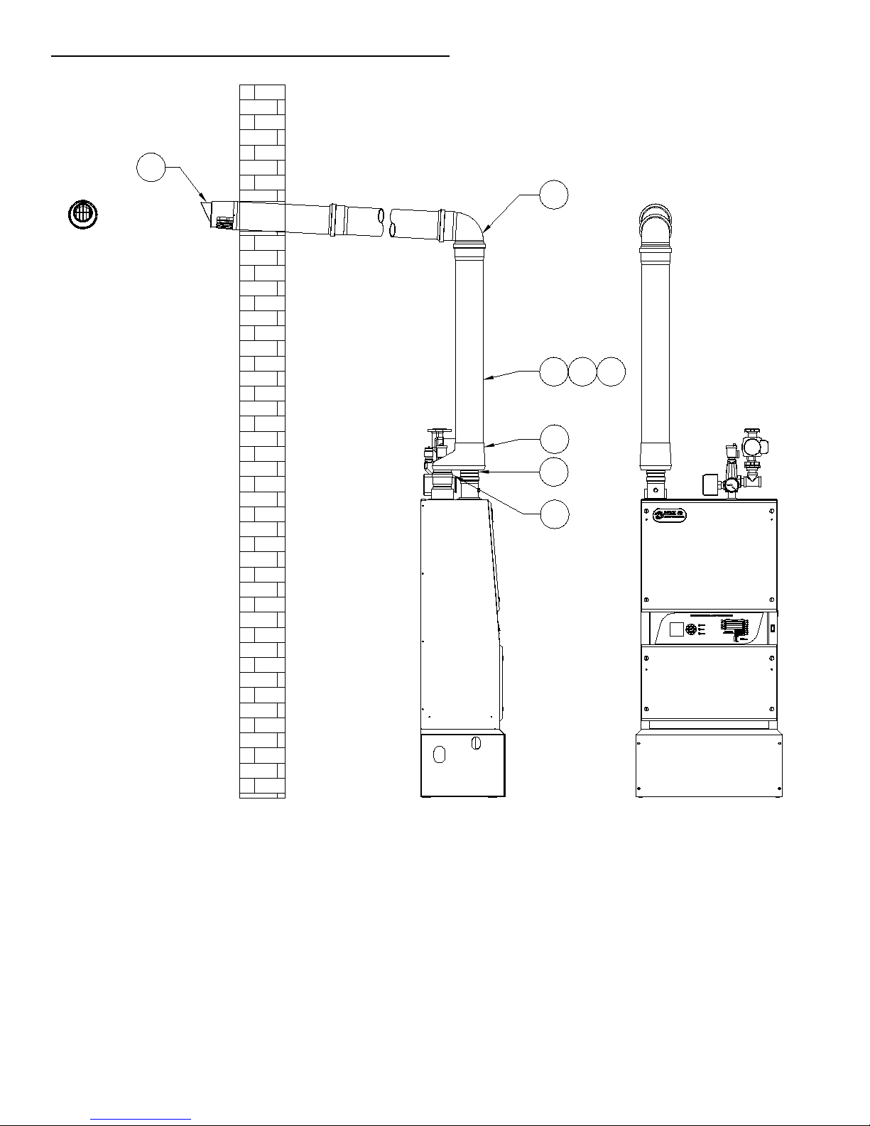
SIDEWALL VENT I NG WITH POLYPROPYLENE – Snorkel style
12"Min/15"Max
Vert Separation
Elbows Should be Flush
with Wall/Outer Plate
Bird Screens must
be Installed in both
openings
Exterior Vent Components
May be Fixed Using One
Stainless Steel Screw
Air Inlet Terminations
Must Point Down
Vent Terminations
Must Point Outwards
12" Min / 15" Max
Vertical Separation
12"Min Above
Expected Snow Level
Air Inlet Terminations
Must Point Down
16
18
21
1
12
8
23
A Short Piece of Vent Pipe
Should be Installed into Bell
of the Elbow First, Then the
Bird Screen Installed into it.
6
7
201110
22
19
4*
14*
* Locking rings must be used on
each joint located indoors
UV Resistant parts should be
used on all exterior venting.
2” or 3” non-concentric side wall vent termination, snorkel style.
Part No: Description:
10-0581 Sidewall Vent Kit 2in PPs
10-0580 Sidewall Vent Kit 3in PPs
10-0587 Sidewall Vent Kit 4in PPs
VENTING GUIDELINES WHEN USING TWO PIPES (SNORKEL STYLE)
1. Vertical Separation: The exhaust vent must be above the air inlet between 12” and 15”. The air inlet must be a
minimum of 12” (24” preferred) above maximum anticipated snow level.
2. Horizontal Separation: The horizontal distance between the air inlet and the exhaust vent must be a minimum of 4”
center to center.
3. The outdoor portion of a snorkel style vent should be limited to 4 feet between elbows. Longer runs may require
insulation and/or a chimney chase to prevent condensation and freezing in the vent; the chase must provide access
for vent pipe inspection
2” Non-concentric side wall vent termination kit, snorkel style
3” Non-concentric side wall vent termination kit, snorkel style
4” Non-concentric side wall vent termination kit, snorkel style
Accel CS Boiler - Gas Heat - Eighth Edition – January, 2015 19
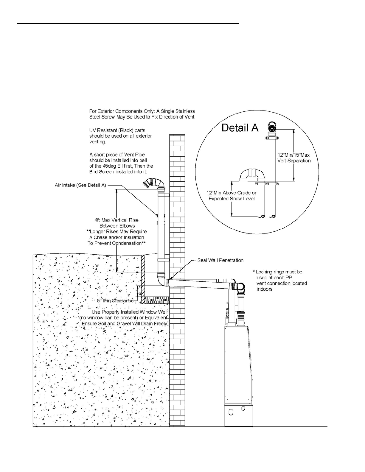
BELOW GRADE SIDEWALL VENTING WITH POLYPROPYLENE – Snorkel style
2” or 3” non-concentric side wall vent termination, snorkel style.
VENTING GUIDELINES WHEN USING TWO PIPES (SNORKEL STYLE)
1. Use a properly insta lled w in do w well (no windo w pres e nt) or equivalently constructed well with adequate drainage
2. Wall penetration must be at least 5” above the bottom of the window well.
3. Vertical rise must be limited to 4 feet maximum between elbows (see figure below); longer runs may require a
chimney chase and/or insulation on the vent to prevent condensation and freezing.
4. Vertical Separation: The exhaust vent must be above the air inlet between 12” and 15”.
5. Horizontal Separation: The horizontal distance between the air inlet and the exhaust vent must be a minimum of 4”
center to center.
Accel CS Boiler - Gas Heat - Eighth Edition – January, 2015 20
SIDEWALL VENT I NG WITH POLYPROPYLENE - Concentric
32
1
3
29
28
26
30 31
Concentric through the wall termination, with 3” piping
Note:
For Centrotherm: Made from black PPS-UV outer and PPS-UV inner, the concentric wall termination incorporates flue
gas termination and combustion air intake. Use with InnoFlue® Concentric or with InnoFlue® SW by adding an ICTC
Adapter.
For DuraVent: Includes 2 appliance adapters, white wall plate, white fire stop, co-linear adapter, White Termination with
Bird Guard Screen, UV resistant.
Accel CS Boiler - Gas Heat - Eighth Edition – January, 2015 21

VENTING VERTICALLY WITH POLYPROPYLENE
Description
Centrotherm
Part No.
DuraVent Part
No.
2” Chimney Liner Kit, with 35 ft of flex
IFCK0235
N/A
3” Chimney Liner Kit, with 35 ft of flex
IFCK0335
N/A
3” Chimney Liner Kit, with 35 ft of flex
IFCK0435
N/A
2” Chimney Liner Kit, order flex separately
N/A
2PPS-FKL
3” Chimney Liner Kit, order flex separately
N/A
3PPS-FKL
4” Chimney Liner Kit, order flex separately
N/A
4PPS-FKL
2” Flex lining, 35 feet
IFVL02035
2PPS-FLEX35
3” Flex lining, 35 feet
IFVL03035
3PPS-FLEX35
4” Flex lining, 35 feet
IFVL04035
4PPS-FLEX35
Part No: Description:
10-0582 Chimney Vent Kit 2in PPs
10-0583 Chimney Vent Kit 3in PPs
10-0586 Chimney Vent Kit 4in PPs
The Accel CS boiler may be installed with polypropylene vent materials
vertically through the roof of a building.
Combustion air may be piped alongside the vertical vent using a dedicated
polypropylene lin er or PVC p ip e. Combustion air may also be taken directly
from the boiler room, although piping combustion air directly from the
outdoors is the best practice.
Chimney Liner
A masonry chimney will not stand up to the corrosive nature of the flue gas
from a condensing boiler. The chimney therefore must have a liner installed
that complies with UL 1738. An existing chimney may be used as a chase
for an approved liner.
Any chimney liner must be made from AL29-4C stainless steel alloy or
approved polypropylene product that is designed for positive pressure
venting. The chimney liner length must be added to the rest of the flue
piping to determine the allowable maximum length.
Optional Venting parts, order as needed for the job.
Notes:
For Centrotherm: Includes all components necessary to line a chimney from chimney termination to base support. Rigid
vent lengths, elbows and adapters required to connect chimney kit base support to appliance are sold separately.
Kit includes 35 feet of flex.
For DuraVent: Use for a vertical flex lining system. Includes black UV resistant chimney cap, rigid flue vent, flex support
bracket, 4 spacers in 3” kits, male and female flex adapters with gaskets, extended support elbow, wall plate and Appliance
adapter. Flex sold separately.
Accel CS Boiler - Gas Heat - Eighth Edition – January, 2015 22
 Loading...