

ENERGY KINETICS System 2000, EK2 Frontier, EK1 Frontier Installation & Service Manual

®
Frontier Boilers
This product meets the Energy Star®
guidelines for efficiency.
®
National
Board Listed
EK1 Frontier and EK2 Frontier
INSTALLATION & SERVICE MANUAL
GAS HEAT EDITION
Manufactured By:
Energy Kinetics, Inc.
MH27877
ANSI Z21.13-2005
CSA 4.9-2005
Low-Press Boiler
INSTALLER: PLEASE HANG THIS INSTRUCTION MANUAL AND ACCESSORY INSTRUCTIONS VISIBLY
CONSUMER: PLEASE RETAIN THIS INSTRUCTION MANUAL AND ACCESSORY INSTRUCTIONS FOR
51 Molasses Hill Road
Lebanon, NJ 08833
(908) 735-2066
www.energykinetics.com
NEXT TO THE BOILER USING THE SUPPLIED POUCH.
FUTURE REFERENCE.
ASME certified by EKI.
Certificate plate is under
the jacket on the steel
vessel.
Frontier Gas Heat – PN 10-2027 – July 2016
PLEASE READ THIS FIRST
Special Attention Flags
Please pay particular attention to the following flags when you see them throughout this manual.
DANGER: Notifies you of hazards that WILL cause severe personal injury, death or substantial property damage.
WARNING: Notifies you of hazards that CAN cause severe personal injury, death or substantial property damage.
CAUTION: Notifies you of hazards that WILL or CAN cause minor personal injury or property damage.
NOTICE: Notifies you of special instructions on installation, operation, or maintenance that are important, but not
normally related to injury or property damage hazards.
WARNING: If the information in this manual is not followed exactly, a fire or explosion may
result, causing property damage, personal injury or loss of life.
WARNING: Do not store or use gasoline or other flammable vapors and liquids in the vicinity of
this or any other gas appliance.
Provide unobstructed combustion air openings sized and located per boiler manual
and applicable codes.
WHAT TO DO IF YOU SMELL GAS
Do not try to light any appliance.
Do not touch any electrical switch; do not use
any phone in your building.
Immediately call your gas supplier from an outside phone.
Follow the gas supplier’s instructions.
If you cannot reach your gas supplier, call the fire department.
WARNING: Installation and service must be performed by a qualified installer, service
agency or the gas supplier.
Retain this manual for use by your qualified service technician only.
Should you observe unusual or abnormal operation of the burner or
boiler, contact your qualified service technician immediately. Do not
attempt to service or repair this product yourself.
Frontier Gas Heat – PN 10-2027 – June 2018 2

WARNING:
WARNING:
Have the burner/boiler started up and serviced at least once annually by a
qualified service technician. Professional care is necessary to properly service
your equipment and verify it is operating reliably. Failure to properly maintain the
equipment could result in severe personal injury, death or substantial property
damage.
You must keep the area around the burner/boiler free from the following. Failure
to comply could result in severe personal injury, death or substantial property
damage due to potential fire, explosion or equipment damage from corrosive flue
products.
Do not store or use gasoline or other flammable vapors or liquids near or in
the same room as the burner.
Do not use or store laundry products, paint, varnish, thinner or other such
chemicals near or in the same room as the burner/boiler. These chemicals
cause creation of acids in the burner, heat exchanger and vent system that
can cause severe damage.
Do not store combustible materials near or in the same room as the
burner/boiler.
GENERAL CARE AND MAINTENANCE
Please read through the information provided for you in this manual. Ask your qualified
service technician to explain normal operation of your equipment.
Daily inspect the space around the burner/boiler to verify the area is clean and free of the
materials listed above.
Periodically watch the operation of your burner/boiler through an operating cycle to verify
normal operation. If you notice unusual conditions or equipment behavior, contact your
qualified service technician. Follow the instructions on the next page to shut down the
burner/boiler while waiting for the technician.
WARNING: Improper installation, adjustment,
alteration, service or maintenance can cause
property damage, personal injury (exposure to
hazardous materials) or loss of life. Refer to the
user’s information manual provided with this boiler.
Installation and service must be performed by a
qualified installer, service agency or the gas
supplier (who must read and follow the supplied
instructions before installing, servicing, or
removing this boiler. This boiler contains materials
that have been identified as carcinogenic, or
possibly carcinogenic, to humans).
Frontier Gas Heat – PN 10-2027 – June 2018 3

FOR YOUR SAFETY READ BEFORE OPERATING
WARNING: If you do not follow these instructions exactly, a fire or explosion
A. This burner does not have a pilot. It is
equipped with an ignition device which
automatically lights the burner. Do not try
to light the burner by hand.
B. Before OPERATING, smell all around the
boiler area for gas. Be sure to smell next to
the floor because some gas is heavier than
air and will settle on the floor. See below.
WHAT TO DO IF YOU SMELL GAS
Do not try to light any appliance.
Do not touch any electric switch; do not
use any phone in your building
Immediately call your gas supplier from a
neighbor’s phone. Follow the gas
supplier’s instructions.
If you cannot reach your gas supplier, call
the fire department.
may result causing property damage, personal injury or loss of life.
C. Use only your hand to turn the gas control
knob. Never use tools. If the knob will not
turn by hand, don’t try to repair it, call a
qualified service technician. Force or
attempted repair may result in a fire or
explosion.
D. Do not use this boiler if any part has been
under water. Immediately call a qualified
service technician to inspect the boiler and
to replace any part of the control system
and any gas control, which has been under
water.
OPERATING INSTRUCTIONS
1. STOP! Read the safety information above.
2. Set the thermostat(s) to their lowest setting.
3. Turn off all electrical power to the burner/boiler.
4. This burner is equipped with an ignition device which automatically lights the burner.
5. Do not try to light the burner by hand.
6. Turn Gas control knob clockwise to OFF.
7. Wait five (5) minutes to clear out any gas. Then smell for gas, including near the floor. If you
smell gas, STOP! Follow the safety information above. If you don’t smell gas, go to the next
step.
8. Turn Gas control knob counterclockwise to ON.
9. Set thermostat(s) to desired setting.
10. Turn on all electric power to the burner and boiler.
11. If the burner/boiler will not operate, follow the instructions “TO TURN OFF GAS TO THE
BURNER” below and call your service technician or gas supplier.
TO TURN OFF GAS TO THE BURNER
1. Set thermostat(s) to their lowest setting.
2. Turn off all electric power to the burner and boiler if service is to be performed.
3. Turn Gas control knob clockwise to OFF. Do not force.
Frontier Gas Heat – PN 10-2027 – June 2018 4

TABLE OF CONTENTS
EK1 Frontier and EK2 Frontier ................................................................................................................................................ 1
INSTALLATION & SERVICE MANUAL .................................................................................................................................... 1
GAS HEAT EDITION ................................................................................................................................................................. 1
PLEASE READ THIS FIRST ..................................................................................................................................................... 2
TABLE OF CONTENTS ............................................................................................................................................................ 5
SCOPE ....................................................................................................................................................................................... 6
SYSTEM 2000
SYSTEM 2000 BOILER - PRINCIPLE of OPERATION ........................................................................................................... 7
DIGITAL MANAGER - PRINCIPLE of OPERATION ................................................................................................................ 7
RECEIVING and UNPACKING ................................................................................................................................................. 8
LOCATION and CLEARANCE ................................................................................................................................................. 8
CLEARANCE for CLEANING and SERVICE ........................................................................................................................... 9
COMBUSTION AIR .................................................................................................................................................................. 9
VENTING ................................................................................................................................................................................... 9
CHIMNEY CONNECTOR ........................................................................................................................................................ 10
CHIMNEY VENTING ................................................................................................................................................................ 10
L-VENT CHIMNEY ................................................................................................................................................................... 10
B-VENT CHIMNEY .................................................................................................................................................................. 11
SIDEWALL VENTING ............................................................................................................................................................. 11
VENTING MATERIALS ........................................................................................................................................................... 11
REMOVAL FROM COMMON VENT SYSTEM ....................................................................................................................... 11
GAS BURNER MOUNTING .................................................................................................................................................... 12
GAS BURNER SETTINGS ...................................................................................................................................................... 12
GAS PIPING SYSTEMS .......................................................................................................................................................... 12
GENERAL ASSEMBLY ........................................................................................................................................................... 13
BOILER MOUNTING ............................................................................................................................................................... 13
PIPING ..................................................................................................................................................................................... 15
ZONE CONTROL .................................................................................................................................................................... 15
FILLING WITH WATER, VENTING, and PURGING .............................................................................................................. 16
BOILER WATER TREATMENT .............................................................................................................................................. 16
ANTI-FREEZE.......................................................................................................................................................................... 16
WINTERIZING.......................................................................................................................................................................... 16
LINE VOLTAGE WIRING DIAGRAMS ................................................................................................................................... 17
WIRING and CONTROLS ....................................................................................................................................................... 17
ELECTRICAL CONNECTION - LINE VOLTAGE ................................................................................................................... 18
LOW VOLTAGE WIRING ........................................................................................................................................................ 18
START UP PROCEDURE ....................................................................................................................................................... 24
The AIR-FREE METHOD of MEASURING CO ...................................................................................................................... 25
GAS BURNER OPERATION ................................................................................................................................................... 25
OUTPUT SIDE ................................................................................................................................................................ 27
2-Minute Energy Manager Diagnostic .................................................................................................................................. 28
Step 1: ..................................................................................................................................................................................... 28
Make sure you have no thermostat calls (turn thermostats down or disconnect after labeling zones). ...................... 28
Additional Manager Tests ..................................................................................................................................................... 29
Line Voltage Relays ............................................................................................................................................................... 30
Surge Suppression ................................................................................................................................................................ 30
NOTE for sidewall vent systems: Add a 120VAC jumper from BURN to IND. This will run the inducer continuously,
so caution should be used in systems without antifreeze.ANNUAL TUNE UP & INSPECTION .................................... 32
Step 3 Inspect Flue Passage ................................................................................................................................................ 33
Annual Tune Up & Inspection ............................................................................................................................................... 34
Step 3 Open Front ................................................................................................................................................................ 34
REPLACEMENT PARTS ......................................................................................................................................................... 35
AMULET REPLACEMENT ...................................................................................................................................................... 35
COMBUSTION CHAMBER REPLACEMENT ......................................................................................................................... 35
®
FRONTIER BOILER ........................................................................................................................................ 7
Frontier Gas Heat – PN 10-2027 – June 2018 5

RECORD OF INSTALLATION
INSTALLER NAME:
INSTALLER ADDRESS:
INSTALLER CITY, STATE:
DATE INSTALLED:
NOTES:
SCOPE
This manual covers the Energy Kinetics System 2000 Frontier Boiler. The boiler is designed and equipped and has
been tested to generate hot water in a low pressure closed loop system. The boiler is a major component of a closed loop
system that can be used as a heat source for hydronic, radiant, domestic hot water, spa, and/or pool heating systems. Call
Energy Kinetics to obtain piping and wiring instructions for applications, such as hydronic he ating, radiant heating, domestic
hot water, swimming pool heating, multiple boilers, injection loops, etc. The installer of the system is responsible for the
final design of the system and for adding the balance of the needed parts to complete the system.
COMMONWEALTH OF MASSACHUSETTS
When the boiler is installed within the Commonwealth of Massachusetts:
This product must be installed by a licensed plumber
If antifreeze is used, a reduced pressure backflow preventer device shall be used.
INSTALLER NOTE:
ALL INSTALLATIONS MUST BE MADE IN ACCORDANCE WITH ALL NATIONAL, STATE AN D LOCAL,
PLUMBING, HEATING AND ELECTRICAL CODES THAT MAY DIFFER FROM THIS MANUAL AND IN
ACCORDANCE WITH THE FOLLOWING CODES, AS APPLICABLE:
N.F.P.A. No. 70: National Electrical Code
Canadian Electrical Code, Part I
A.N.S.I. / N.F.P.A. No. 211: Chimneys, Fireplaces, Vents and Solid Fuel Burning Appliances
A.N.S.I. Z223.1 / N.F.P.A. No. 54: National Fuel Gas Code
If this gas fired boiler is converted to oil fired by field mounting a listed oil burner, then install in accordance
with A.N.S.I. / N.F.P.A. No. 31: Installation of Oil Burning Equipment
These codes are available from:
National Fire Protection Association
1 Batterymarch Park
Quincy, MA 02269-9101.
A hot water boiler installed above radiation level or as required by the Authority having jurisdiction, must be
provided with a low water cutoff device.
A boiler should be installed in such a manner that, if the pressure vessel or any connection thereto should leak,
the resulting flow of water will not cause damage to the area in which it is installed.
A hot water storage tank should be installed in such a manner that, if the storage tank or any connection thereto
should leak, the resulting flow of water will not cause damage to the area in which it is installed.
A boiler’s pressure relief valve, hot water storage tank T&P relief valve, backflow preventer, and all other
devices must be piped to the nearest drain to avoid damage in the event the valve is actuated.
Make sure relief discharge pipes from all reliefs are properly placed to safely contain discharge. Make sure
relief discharge pipes, such as from a boiler or a hot water storage tank, will safely contain hot water and/or
boiling water. Make sure relief discharge pipes, such as from a boiler or a radiant heating system, will safely
contain water treated with boiler chemicals and/or antifreeze. Reliefs include the boiler pressure relief valve, the
back flow preventer discharge port, and the domestic hot water tank temperature and p ressure relief valve. Any
other reliefs, such as from radiant heating systems, must also follow these guidelines.
Frontier Gas Heat – PN 10-2027 – June 2018 6

SYSTEM 2000® FRONTIER BOILER
IMPORTANT MESSAGE TO HOMEOWNER: These instructions should be carefully read and kept for future reference to
gain the best performance from your System 2000 Frontier boiler.
CONGRATULATIONS ON YOUR PURCHASE OF THE SYSTEM 2000 BOILER with its highly efficient low mass hydronic
heat exchanger, the Energy Converter. It is the product of years of engineering and advanced design, which brings
together in a single system all elements needed to provide efficient home heat. This operation and maintenance
information has been prepared so that you may better understand and use your Energy Kinetics Frontier Boiler and
Heating System.
SYSTEM 2000 BOILER - PRINCIPLE of OPERATION
SYSTEM 2000 comprises a heat source, the energy converter, circulating water and five (or more) zones controlled by an
electronic control, the Digital Manager.
The Boiler sits cold until a thermostat calls for heat. The Digital Manager receives the call for heat and turns on the
main circulator and burner. Water circulates within the boiler as it warms up to operating temperature. When ready, the
zone valves open and deliver heat to the zones calling for heat. When the thermostats are satisfied, the Digital Manager
turns off the burner and enters the energy recovery stage. The circulator and zone valve stay energized to deliver the heat
remaining in the boiler to your home.
When energy recovery is complete and the Boiler has been cooled off, the Digital Manager turns off the system and
waits for another thermostat (or tank aquastat) to call for heat. SYSTEM 2000 runs the burner only when you need heat
and delivers that heat only where you need heat.
The System 2000 Energy Converter is the product of advanced thermal engineering. It is designed with two separate
passageways, nearly 10 feet long, coiled around each other. Water travels along one passageway from your home toward
the center of the unit and heated gases travel from the unit center toward the chimney. This is a “forced circulation counterflow” design and it provides very efficient transfer of heat from the burning fuel to the circulating water. The superior
insulation of the boiler minimizes heat losses to the surroundings, resulting in directing heat to your home in an efficient and
quiet manner.
SYSTEM 2000 has an extremely high annual efficiency (over 99% of steady state) because it runs only when your
home needs heat. Energy recovery is completed at the end of each heat call, virtually eliminating off cycle losses.
Your System 2000 holds a minimal quantity of water so it begins to supply heat in about 90 seconds. This rapid
response means that your rooms can be heated quickly to temperature. The System 2000 EK-1 Frontier can heat water up
to 100,000 BTU’s per hour and the EK-2 Frontier up to 200,000 BTU/hr.
A modern power burner fires into the center of System 2000 where a high temperature, light weight ceramic chamber
provides ideal conditions for “near perfect” efficient, pollution-free combustion. Your System 2000 is tightly sealed so all
products of combustion pass only to the chimney.
The FRONTIER Boiler is designed with a hinged front cover that allows access to the inside of the boiler for inspection
and cleaning. All access for service is from the front, so the FRONTIER Boiler can be placed directly against a wall or into
a closet.
DIGITAL MANAGER - PRINCIPLE of OPERATION
The left side of the Manager is the input side, which provides 24-volt power supply and connections for thermostats.
The right side is the output side, which starts the burner, circulator and zone valves or zone circulators. See photo of the
Manager on the cover.
Lights on the Digital Manager indicate what is calling for heat (left side) and (right side) lights indicate active zone(s),
burner operation and circulator operation. These function lights are an aid in servicing. The following is a typical cycle.
1. SYSTEM WAITING FOR A CALL: The boiler is turned off and sits cold, waiting until a call for heat. The blue power
light on the Manager is on.
2. CALL FOR HEAT: A room thermostat call starts the cycle. The thermostat light on the left side will turn on for that
zone.
3. PRE-HEAT: Output lights for the main circulator and burner turn on, the circulator starts, and the burner begins firing.
The boiler water circulates through the energy converter via the bypass line, heating up the water.
4. HEAT: Once the boiler water has heated up to 150
light on the right side. The zone valve will open and hot water will flow to the zone needing heat. The burner runs as
long as there is a thermostat calling and as long as heat is being delivered to the zone. The burner may shut off if the
return temperature exceeds 170
o
F/190o F (RED burner light turns off) or if the high limit temperature is exceeded (RED
burner light stays on, but the high limit aquastat shuts the burner off).
5. ANOTHER CALL FOR HEAT: If another zone calls for heat while the burner is already running and the return
temperature is above 150
o
F, the zone output will turn on, immediately supplying heat to the zone.
o
F (about 90 seconds), the Manager will turn on the zone output
Frontier Gas Heat – PN 10-2027 – June 2018 7
6. MONITOR RETURN TEMPERATURE: The Manager continually senses the return temperature and will turn off the
zone outputs if the return temperature drops below 120
closed, the boiler water will quickly reheat and once the return temperature reaches 140
o
F (130o F if Option Switch #1 is ON). With the zone outputs
o
F (150o F if Option Switch #1
is ON), then the Manager will reopen the zone valves.
7. THERMOSTAT (or Aquastat) SATISFIED: The thermostat light on the left side will go out. The burner light and the
burner will then turn off.
8. ENERGY RECOVERY: The circulator and zone valve remain energized. The circulating water will remove the energy
from the converter, sending the heat to the last zone that called. The energy recovery stage continues until the return
temperature has dropped sufficiently or until maximum timing has been reached. The boiler is now sitting cold, waiting
for the next call for heat. Maximum timing for heat recovery stage is usually set at twenty minutes for space heating
zones and is fixed at five minutes for Zone HW. (See Digital Manager Option Switch Settings).
.
RECEIVING and UNPACKING
Inspect shipment upon receipt for external damage. When unpacking and uncrating, inspect each item for internal
damage. Any damage found should immediately be reported to the freight carrier before installation. The receiver is
responsible for following the claims procedure of the freight carrier. The freight carrier is responsible for taking prompt
action on all claims. If freight cannot be inspected at the time of delivery, sign the bill of lading “Subject to Inspection” and
inspect the shipment as soon as possible after receipt. Replacements for parts damaged in shipment are available upon
receipt of a signed copy of a claim report (concealed damage claims should be filed immediately against the freight carrier
by the consignee).
After unpacking, check each item against the packing list. Inspect it thoroughly for loose parts, instruction sheets and
packing lists. Immediately report any missing items. It is wise to complete the installation before discarding packing
material. Store all parts where they will not be damaged or lost during installation.
LOCATION and CLEARANCE
DANGER: Provide clearance to combustible surfaces in accordance with all local and national codes. Follow National
Fire Protection Association Bulletin NFPA Installation of Gas Burning Equipment and all applicable codes.
Installation Clearances from Boiler Surfaces, Inches Clearance to Combustibles Clearance for Service
Front of boiler 15 1/2 20
Left side of boiler body 0 0
Right side of boiler body 0 0
Back of boiler body 4 4
Top of boiler body 16 16
Bottom of boiler legs to floor 0 16*
B-Vent (gas only): from flue pipe 3 3
L-Vent: from flue pipe 3 3
Standard Flue: from flue pipe 9 9
*Minimum recommended clearance to allow the door to fully open.
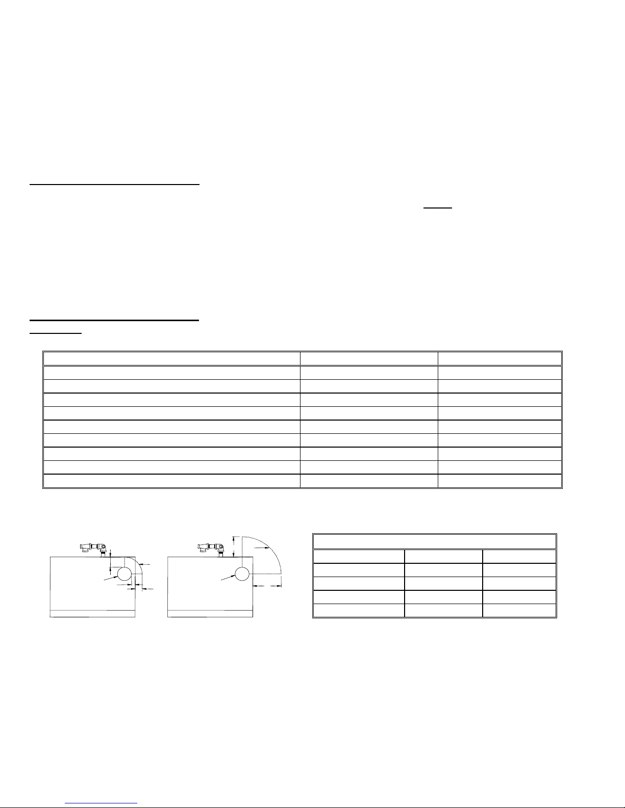
Figure 1A. Top View of Boiler -
Flue Connection Clearance to Combustibles
TYPICAL FLUE
CONNECTION
(A) L-VENT OR PELLET VENT
3”
1"
3”
TYPICAL FLUE
2"
CONNECTION
(B) STANDARD VENT PIPE
6"
9”
8"
Boiler Weight and Water Content
Model EK-1 Frontier EK-2 Frontier
Weight 270 lbs 350 lbs
Water Content 2-1/2 gallons 4 gallons
Air Inlet Pipe Size 2 " 3 "
Boiler Flue Outlet 4 " 6 "
Frontier Gas Heat – PN 10-2027 – June 2018 8
CLEARANCE for CLEANING and SERVICE
Installations should utilize one of Energy Kinetics boiler stands to provide a solid, level, and smooth foundation for the
boiler. NOTICE: Do not install on carpeting. Place the unit as near to the chimney or vent as possible allowing clearance
for front cleaning and service as shown in Figure 1B. If not using an Energy Kinetics supplied stand, provide a solid, level,
smooth, foundation with clearance for door opening and service. NOTICE: The stand must be level to allow for proper
venting of air from the boiler. The Frontier is manufactured with the BACK of the boiler higher than the front to assist in air
removal.
* Height of Frontier on a Low Profile Base
** Height of Frontier on a Standard Boiler Base
EK1: 41" / EK2: 49"
EK1: 21-1/2"
24"
SYSTEM 2000
ENERGY MANAGER
HOT WATER
Z4
THW
1
1
ZHW
T1
2
2
Z1
T2
3
3
T3
Z2
4
4
Z3
A1
A2
24VAC
INDUCER
TEMP. SENS.
B
S
R
T4
9"
IND
ERGY
EN
BURNER
B1
ETICS
KIN
CIRCULATOR
Lebanon, New Jersey
B2
CIRC
CAUTION
30"
48"*
56"**
9"*
17"**
EK2: 29-1/2"
12-3/4"
Figure 1B – Boiler Clearance for Clearing and Service
73"
9"
30"
34"
24"
THW
1
T1
2
T2
3
T3
4
A1
A2
TEMP. SENS.
B
EN
S
KIN
Lebanon, New Jersey
R
T4
CAUTION
NOTE:
Tank Stand
Allows The Boiler
To Be Mounted
Over Top Of a 40
Gal Lo-Boy Tank.
29-1/4"
SYSTEM 2000
ENERGY MANAGER
HOT WATER
Z4
1
ZHW
2
Z1
3
Z2
4
Z3
24VAC
INDUCER
IND
ERGY
BURNER
B1
ETICS
CIRCULATOR
B2
CIRC
NOTE:
All piping
(hydronic, gas &
inlet air) must
allow clearance
for door opening.
EK1: 41" / EK2: 49"
EK1: 21-1/2"
EK2: 29-1/2"
11-5/8"
COMBUSTION AIR
The System 2000 Boiler must be installed in an area where adequate fresh air is available to support combustion. The
Frontier is provided with a sealed Air Box that can be piped to air outside the building. Piping of outside air directly to the
boiler is highly recommended because it completely isolates the boiler from the home environment, as well as greatly
reducing operating noise from the boiler.
Boiler with outside air piping: In modern houses with tight construction the connection of the Air Box to an outside air
source to provide combustion air is highly recommended. The outside air source must be lo cated high enough above grade
to be at least 12” above expected snow accumulation.
WARNING: For systems with sidewall venting, combustion air piping from outside the building is required. The
Energy Kinetics sidewall vent kit contains specific instructions for installation that must be followed. Combustion air may be
supplied through PVC pipe. For EK-1 use, 2" pipe up to 20 feet in length with up to (5) 90-degree elbows. For EK-2 use, 3"
pipe up to 20 feet in length with up to (5) 90-degree elbows. A total equivalent length of 45 feet is allowed. Each 90-degree
elbow is the equivalent of 5 feet of straight pipe. For example, if three 90-degree elbows are used, then the length of pipe
run may increase to 35 feet. An unglued or Tek-screw joint allows the door to swing down when the air inlet pipe is
disconnected.
WARNING: Modern buildings of tight construction, as well as the operation of attic and exhaust fans, kitchen ventilation
systems, clothes dryers or fireplaces may create conditions of unsatisfactory combustion or venting. Provisions must be
made to use combustion air that communicates with a well-ventilated attic or with the outdoors (such as using a louver or
grate). The opening should have a free area of not less than one (1) square inch per 4,000 BTU per hour of the total input
rating.
Boiler without outside air piping:
WARNING: The confined space shall be provided with two permanent openings, one near the top of the enclo sure and
one near the bottom. Each opening shall have a free area of not less than one square inch per 1,000 BTU per hour of the
total input rating of all appliances in the enclosure, freely communicating with interior areas having adequate infiltration from
the outside.
VENTING
When connecting the Gas Heat version of the Energy Kinetics SYSTEM 2000 boiler to gas vents or chimneys, all vent
installations shall be in accordance with Part 7, Venting of Equipment, of the National Fuel Gas Code, ANSI Z223.1/NFPA
54, or Section 7, Venting Systems and Air Supply for Appliances, of the CAN/CGA B149, Installation Codes, or applicable
provisions of the local Building Codes. Vent connectors serving appliances vented by natural draft shall not be connected
into any portion of mechanical draft systems operating under positive pressure.
WARNING: No solid fuel appliance or fireplace should be installed in a flue common with this heating appliance.
Frontier Gas Heat – PN 10-2027 – June 2018 9

CHIMNEY CONNECTOR
Chimney connectors should be positioned to give the shortest possible run of flue pipe to the chimney. The overall
horizontal length of single wall flue piping should not exceed approximately 15 feet. Long runs may require insulated flue
pipe such as B-Vent or L-Vent to keep the temperature at base of chimney adequate for draft and to prevent corrosion of
piping and connectors. Because the System 2000 boiler uses a power burner, the flue pipe may experience some positive
pressure on start up. Energy Kinetics recommends that all pipe joints be sealed with high temperature silicone sealant to
ensure passage of all combustion products to the chimney.
Horizontal portions of the venting system shall be properly supported to prevent dips or sagging. Follow vent pipe
manufacturer’s instructions for proper support of the vent pipe at the intervals specified by the vent pipe manufacturer.
Pitch horizontal flue pipe up toward chimney not less than ¼” per foot.
CHIMNEY VENTING
WARNING: Masonry chimneys must have a tile or metal liner. The liner must:
1) Extend above the masonry.
2) Have an insulating air gap, isolating the liner from the chimney, allowing for rapid heat-up and draft establishment.
3) Be sealed at each joint to prevent air infiltration and damage from condensation.
NOTICE: Inspect Chimney and Chimney base after initial three months of heating season.
The installation of a chimney cap is recommended. The base of the chimney must always have a drop leg below the
flue connector to allow scale and condensation to accumulate without blocking the flue pipe.
CAUTION: If drop leg is in excess of 12 inches deep, backfill with loose gravel or sand to obtain a maximum of 12-inch
depth. All clean out doors must be sealed to prevent cold air entry into chimney.
In retrofit installations, have chimney thoroughly cleaned. Carefully inspect chimney, base of chimney, and liner prior to
installation of System 2000 Boiler.
CAUTION: If liner is not sound or if existing tile liner fails to contain intermittent condensation, or if excessive debris is
found at the base of the chimney, then it is recommended to install a properly sized metal liner approved for use with gas
heat appliances.
The metal chimney liner diameter and length should be as recommended by the metal chimney liner manufacturer.
Corrugated metal liners should be at least 5" diameter for EK-1 and 6" diameter for EK-2. Call Energy Kinetics for details
on metal liners.
Chimney connectors should be positioned to create the shortest possible run of flue pipe to the chimney. Energy
Kinetics has flexible metal chimney connectors available that are 5’ in length and are to be used between the boiler flue
collar and the chimney. Chimney connectors are 5” diameter with 5” X 4” adapter for EK1 and 6” diameter for EK2. The
overall horizontal length of flue piping should not exceed 15 feet. Long runs or low firing rates may require insulated flue
pipe such as L-Vent or All-Fuels to keep the temperature at base of chimney adequate for draft and to prevent corrosion of
piping and connectors.
Because the System 2000 boiler uses a power burner, the flue pipe may experience some positive pressure on start
up. Energy Kinetics recommends that all pipe joints be sealed with high temperature silicone sealant to ensure passag e of
all combustion products to the chimney.
Normally, pitch horizontal flue pipe up toward chimney approximately ¼” per foot. For existing installations, it is
permissible for the flue connection of the boiler to be higher than the chimney thimble, provided adequate d raft is
established.
If a minimum of -0.02” w.c draft over fire is not present after sufficient burner run time to heat up the chimney, there is a
problem that will need to be corrected. Call Energy Kinetics for help resolving draft problems. Under normal
circumstances, there is NO need for a DRAFT REGULATOR and one should not be installed. Call Energy Kinetics with
questions about flue pipe sizing.
WARNING: No solid fuel appliance or fireplace should be installed in a flue common with this heating appliance. The flue
gas exit of the venting system must be at least three (3) feet above the point at which it passes through the roof and at least
two (2) feet higher than any portion of a building within 10 feet horizontally of its location.
L-VENT CHIMNEY
Gas Heat SYSTEM 2000 Boilers at high firing rates may have flue gas temperatures between 470o F and 530o F during
normal operation. When flue gas temperatures are below 570
Gas Heat SYSTEM 2000 Boilers. Type L gas vent chimney pipe is double walled and may allow smaller chase dimensions
than other chimney pipe materials and should be considered for new installations with Gas Heat SYSTEM 2000 Boilers.
A Type L gas vent system shall extend at least five (5) feet of height above the breech of the boiler.
Refer to the section on Gas Vent Termination in the National Fuel Gas Code to determine Minimum Height from Roof to
Lowest Discharge Opening required.
Type L gas vent must be U.L. Listed to U.L. 641. Type L gas vent to be installed and supported in accordance with the
vent manufacturer’s instructions.
o
F, Type L gas vent chimney pipe is suitable for use with
Frontier Gas Heat – PN 10-2027 – June 2018 10

Gas Heat System 2000 boilers and Type L gas vent must be installed in strict compliance with all State and Local
Codes and with the regulations of the authorities having jurisdiction, which may differ from and which take precedence over
these instructions or the vent manufacturer’s instructions.
B-VENT CHIMNEY
Gas Heat SYSTEM 2000 Boilers at factory default firing rates have flue gas temperatures between 350o F and 450o F
during normal operation. Refer to the burner settings table for the default firing rates. Due to the low flue gas
temperatures, Type B gas vent chimney pipe is suitable for use with Gas Heat SYSTEM 2000 Boilers. Type B gas vent
chimney pipe is double walled and may require smaller chase dimensions than other chimney pipe materials and should be
considered for new installations with Gas Heat SYSTEM 2000 Boilers.
A Type B gas vent system shall extend at least five (5) feet of height above the breech of the boiler.
Refer to the section on Gas Vent Termination in the National Fuel Gas Code to determine Minimum Height from Roof to
Lowest Discharge Opening required.
Type B gas vent must be U.L. Listed to U.L. 441. Type B gas vent to be installed and supported in accordance with the
vent manufacturer’s instructions.
Gas Heat System 2000 boilers and Type B gas vent must be installed in strict compliance with all State and Local
Codes and with the regulations of the authorities having jurisdiction, which may differ from and which take precedence over
these instructions or the vent manufacturer’s instructions.
SIDEWALL VENTING
1. System 2000 Boilers may be installed with Energy Kinetics' sidewall vent kit in accordance with kit instructions.
WARNING: Sidewall vent systems must have outside air connected to the air box and both air box air intake and
2.
vent hood must be located on the same side of the structure.
3. NOTICE: The sidewall vent inducer should be located above the boiler flue outlet, preferably a minimum of four feet
vertical distance, which will provide some natural draft to the boiler (and cooling of the burner) in case of a powe r
failure. When installing a sidewall venting system from another manufacturer, ensure that the manufacturer’s
instructions are followed. Vent manufacturer should confirm that the equipment is suitable for use with System 2000.
4. Set the draft at the over fire of the boiler to between -.10" to -.12" w.c. with the burner running, after allowing time for
sufficient warm-up. Check/adjust CO
5. To provide power to the sidewall vent, install the plug-in relay supplied with the sidewall vent kit into the junction box
relay board and set the Digital Manager Option Switch #2 to the “ON” (down) position. This enables the “Inducer” light
and allows the Digital Manager to control the inducer. Refer to Digital Manager section for option switch settings and
inducer timing details.
VENTING MATERIALS
Gas Heat SYSTEM 2000 Boilers at factory default firing rates generate exiting flue gas temperatures between 350o F
and 450
o
F during normal operation. The Frontier Gas boiler can be safely vented using a variety of venting materials.
Venting materials should be listed by a nationally recognized testing agency. Any venting material used must be at least
0.020” thickness. Approved materials include stainless steel, such as 316, 316L, 316Ti or AL 29-4C. For gas only
installations, aluminum is also approved. Plastic venting of any type, such as PVC, CPVC, ABS, or PP, is not approved.
Plastic pipe may be safely used for air intake piping, but not for venting.
REMOVAL FROM COMMON VENT SYSTEM
When any existing appliance, such as a boiler, is removed from a common venting system, the common venting system
is likely to be too large for proper venting of the appliances remaining connected to it. Testing of the remaining venting
system must be performed according to the following procedure.
At the time of removal of the existing appliance, the following steps shall be followed with each appliance remaining
connected to the common venting system placed in operation, while the other appliances remaining connected to the
common venting system are not in operation.
1. Seal any unused openings in the common venting system.
2. Visually inspect the venting system for proper size and horizontal pitch and determine there is no blockage or
restriction, leakage, corrosion and other deficiencies, which could cause an unsafe condition.
3. Insofar as is practical, close all building doors and windows and all doors between the space in which the appliances
remaining connected to the common venting system are located and other spaces of the building. Turn on clothes
dryers and any appliance not connected to the common venting system. Turn on any exhaust fans, such as range
hoods and bathroom exhausts, so they will operate at maximum speed. Do not operate a summer exhaust fan. Close
fireplace dampers.
4. Place in operation the appliance being inspected. Follow the lighting instructions. Adjust thermostat so appliance will
operate continuously.
5. Test for spillage after five minutes of main burner operation. Use a draft gauge or pressure gauge to verify that the
vent pipe at the breech of the appliance is under draft (negative pressure) relative to the room.
6. Repeat 4) and 5) for each appliance connected to the common venting system, one appliance at a time.
7. After it has been determined that each appliance remaining connected to the common venting system properly vents
when tested as outlined above, return doors, windows, exhaust fans, fireplace dampers and any other gas-burning
appliance to their previous condition of use.
Frontier Gas Heat – PN 10-2027 – June 2018 11
. Re-check the draft at over fire and adjust draft if necessary.
2
8. Any improper operation of the common venting system should be corrected so the installation conforms with the
National Fuel Gas Code, ANSI Z223.1/NFPA 54 and/or CAN/CGA B149, Installation Codes. When resizing any
portion of the common venting system, the common venting system should be resized to approach the minimum size
as determined using the appropriate tables in Part 11 of the National Fuel Gas Code, ANSI Z223.1/NFPA 54 and/or
CAN/CGA B149, Installation Codes.
GAS BURNER MOUNTING
SYSTEM 2000 Boilers are shipped from the factory with the gas burner mounted. The burner flanges are designed to
insert the burner head 2-3/8” into the boiler. Energy Kinetics installs a ceramic sleeve, (the amulet), to protect the burner
head from the heat of combustion, and then seals the air tube flange joint with a high-grade retort cement.
NOTICE: Gas burners for field installation or for field replacement should be installed according to burner manufacturer
instructions, according to installation instructions below, and with consultation from Energy Kinetics for any special
considerations or adjustments.
Follow these instructions for field installation of Energy Kinetics supplied burners. Start by checking electrode and
flame sense rod position per manufacturer’s specifications prior to assembly to unit. Test fit the amulet by inserting the
amulet into the boiler opening. If the amulet doesn't easily slide into the boiler, then gently sand the outside diameter of the
amulet until it will fit into the boiler opening. Test fit the amulet onto the burner head. The amulet for the Carlin burners has
a smooth interior. If the amulet is a tight fit on the burner head, then slightly moisten inside the amulet with water.
Place a 3/8" bead of retort cement onto the burner head at the flange to air tube joint, and slide the (moistened) amulet
over the burner head and against the flange. Ensure proper seating of the amulet by pressing the amulet onto the burner
with a flat object. Leave the excess retort cement at the amulet to flange joint and the cement will provide an airtight seal of
the air tube flange to the boiler face.
The Carlin amulet does not have an edge and when fully seated the amulet will be flush with the front of the Carlin
burner head. If needed, trim the front edge of the amulet to be flush with the front of the burner head.
Once the amulet has been seated and trimmed, then install the burner into the boiler by carefully inserting the air tube
with amulet into the boiler opening while aligning the burner flange holes with the boiler studs. Install flat washers and nuts
onto the boiler studs and tighten all nuts evenly.
GAS BURNER SETTINGS
EK-1 Boilers are shipped from the factory preset for 120,000 Btu/Hr firing rate and EK-2 Boilers are shipped from the
factory preset for 200,000 Btu/Hr firing rate. The SYSTEM 2000 Boiler can be fired over a range of firing rates to suit the
needs of the application. The following table lists approximate settings for Carlin EZ-Gas burners ba sed on extensive
testing.
CAUTION: Final settings for each burner and firing rate for a particular installation must be determined by using
combustion test equipment and following the instructions given under "Start Up Procedure".
Burner Orifice
Input
Model
Btu/Hr
Chimney
Vent
Sidewall
Natural Gas LPG 1 Slot 2 Slot inches
Drill size
Approximate air
band setting
UTL - air tube
insertion length
Diffuser
80,000 N Y #8 (0.199) #25 (0.149) 25 2-3/8” B
100,000 N Y #1 (0.228) #16 (0.177) 35 2-3/8” B
EK-1
EK-2
* Default Factory Setting
GAS PIPING SYSTEMS
120,000 * Y Y C (0.242) #13 (0.189) 45 2-3/8" B
150,000 Y Y J (0.277) 7/32 (0.219) 60 2-3/8" B
175,000 N Y N (0.302) C (0.0242) 40 2-3/8” A
200,000 * Y Y 21/64 (0.328) 17/64 (0.266) 50 2-3/8" A
225,000 Y Y T (0.358) 9/32 (0.281) 60 2-3/8" A
250,000 Y N X (0.397) 5/16 (0.312) 70 2-3/8" A
The boiler and its individual shutoff valve must be disconnected from the gas supply piping system during any pressure
testing of the gas supply piping system at test pressures in excess of 1/2 psi (3.5 kPa, 14 in wc).
The boiler must be isolated from the gas supply piping system by closing its individual manual shutoff valve during any
pressure testing of the gas piping system at test pressures equal to or less than 1/2 psi (3.5 kPa, 14 in wc).
A manual shut off valve and a sediment trap must be provided in the gas piping upstream of the electric combination
gas valve at the boiler. The boiler and its gas connection must be tested for gas leakage before placing the boiler in
operation.
Frontier Gas Heat – PN 10-2027 – June 2018 12
 Loading...