

ENERGY KINETICS EK1, System 2000, EK2 Owners And Installation Manual
®
Standard Boiler
Owner and Installation Manual
Oil Heat Edition
This product meets the Energy
®
Star
guidelines for efficiency
Energy Kinetics, Inc.
Manufactured By:
51 Molasses Hill Road
Lebanon, NJ 08833
(908) 735-2066
www.energykinetics.com
INSTALLER: PLEASE HANG THIS INSTRUCTION MANUAL AND ASSESSORY INSTRUCTIONS VISIBLY
NEXT TO THE BOILER USING THE SUPPLIED POUCH.
CONSUMER: PLEASE RETAIN THIS INSTRUCTION MANUAL AND ACCESSORY INSTRUCTIONS FOR
FUTURE REFERENCE.
ASME certified by EKI.
Certificate plate is under the
jacket on the steel vessel.
TWENTY NINTH EDITION – JULY 2005

RECORD OF INSTALLATION
INSTALLER NAME:
INSTALLER ADDRESS:
INSTALLER CITY, STATE:
DATE INSTALLED:
NOTES:
INSTALLER NOTE:
ALL INSTALLATIONS MUST BE MADE IN ACCORDANCE WITH ALL STATE AND LOCAL CODES THAT MAY
DIFFER FROM THIS MANUAL.
All installations must be made in accordance with all State and Local Codes, which may differ from this manual and in
accordance with the following Codes, as applicable:
N.F.P.A. No. 70: National Electrical Code
A.N.S.I. / N.F.P.A. No. 31: Installation of Oil Burning Equipment
A.N.S.I. / N.F.P.A. No. 211: Chimneys, Fireplaces, Vents and Solid Fuel Burning Appliances.
If this oil fired boiler is converted to gas fired by field mounting a listed gas conversion burner, then install in accordance
with A.N.S.I. Z223.1/N.F.P.A. No. 54: National Fuel Gas Code
These codes are available from:
National Fire Protection Association
1 Batterymarch Park
Quincy, MA 02269-9101.
Twenty Ninth Edition – July 2005 2
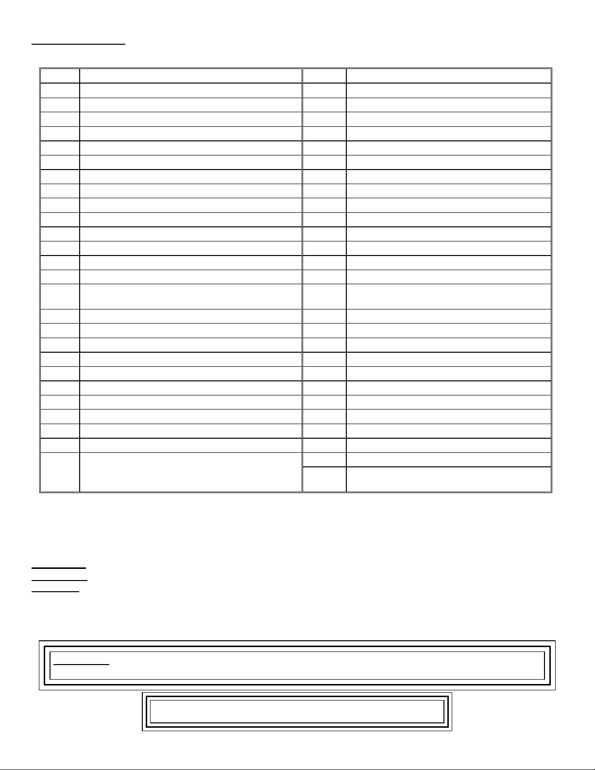
Table of Contents:
Page Topic Page Topic
2 Record of Installation 12 Wiring and Controls
3 Table of Contents 12 Electrical Connection - Line Voltage
3 Please read this first 12 Line Voltage Wiring Diagram
4 SYSTEM 2000 Boiler - Principle of Operation 12 Low Voltage Wiring
5 Digital Energy Manager - Principle of Operation 13 Low Voltage Wiring Diagram
5 Receiving and Unpacking 13 Install Digital Manager
5 Location and Clearance 13 Digital Manager Option Switch Settings
6 Boiler Weight, Water Content, Air Inlet Sizes 14 Hydronic Control Settings
6 Combustion Air 14 Prepare for Start Up
7 Chimney Venting 14 Start Up Procedure
7 L-Vent Chimney 15 Oil Burner Operation
7 Sidewall Venting 16 Expanded Digital Manager Installation
8 Fuel Systems 16 Security System Interface Wiring
8 Oil Burner Settings 17 Digital Manager Operation Summary
8 Oil Burner Mounting 18 Complete Quick Check of the Digital
Manager
9 General Assembly 19 Digital Manager Sensor Testing
9 Boiler Mounting 20 Troubleshooting with Digital Manager
10 Piping 20 Operation without the Digital Manager
10 Zone Control 20 Service Board Mode
10 Hot Water Storage Tank 21 Diagnostics with the Digital Manager
11 Heat Exchanger and Bypass 22 Annual Maintenance
11 Filling with Water, Venting, and Purging 23 Replacement Parts
11 Boiler Water Treatment 23 Amulet Replacement
11 Anti-Freeze 23 Combustion Chamber Replacement
11 Winterizing 24 Assembly Drawing
24 Parts List Inside
Back
Cover
Warranty Transfer Agreement
Back
Cover
Limited Lifetime Warranty
Please Read This First…
Special Attention Flags
Please pay particular attention to the following flags when you see them throughout this manual.
DANGER: Notifies you of hazards that WILL cause severe personal injury, death or substantial property damage.
WARNING: Notifies you of hazards that CAN cause severe personal injury, death or substantial property damage.
CAUTION:
NOTICE: Notifies you of special instructions on installation, operation, or maintenance that are important, but not
Twenty Ninth Edition – July 2005 3
Notifies you of hazards that WILL or CAN cause minor personal injury or property damage.
normally related to injury or property damage hazards.
WARNING: Do not store or use gasoline or other flammable vapors and liquids in the vicinity
of this or any other combustion appliance.
CAUTION: DO NOT TAMPER WITH THE UNIT OR CONTROLS.
SYSTEM 2000® Standard Boiler
IMPORTANT MESSAGE TO HOMEOWNER: These instructions should be carefully read and kept for future reference to
gain the best performance from your System 2000 boiler.
CONGRATULATIONS ON YOUR PURCHASE OF THE SYSTEM 2000 BOILER with it's highly efficient low mass hydronic
heat exchanger, the Energy Converter. It is the product of years of engineering and advanced design, which brings
together in a single system all elements needed to provide efficient home heat and hot water. This operation and
maintenance information has been prepared so that you may better understand and use your Energy Kinetics System
2000 Boiler and Heating System.
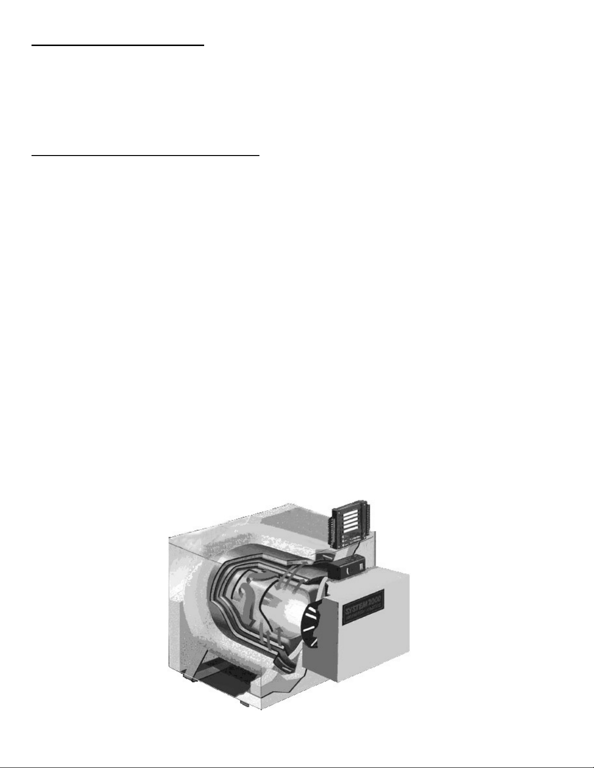
SYSTEM 2000 Boiler - Principle of Operation:
SYSTEM 2000 comprises a heat source, the energy converter, circulating water, a heavily insulated hot water storage tank
and five (or more) zones controlled by an electronic control, the Digital Manager.
The Boiler sits cold until a thermostat calls for heat. The Digital Manager receives the call for heat and turns on the
main circulator and burner. Water circulates within the boiler as it warms up to operating temperature. When ready, the
zone valves open and deliver heat to the zones calling for heat. When the thermostats are satisfied, the Digital Manager
turns off the burner and enters the energy recovery stage. The circulator and zone valve stay energized to deliver the heat
remaining in the boiler to your home or to the domestic hot water storage tank.
When energy recovery is complete and the Boiler has been cooled off, the Digital Manager turns off the system and
waits for another thermostat (or tank thermostat) to call for heat. SYSTEM 2000 runs the burner only when you need heat
and delivers that heat only where you need heat.
The System 2000 Energy Converter is the product of advanced thermal engineering. It is designed with two separate
passageways, nearly 10 feet long, coiled around each other. Water travels along one passageway from your home toward
the center of the unit and heated gases travel from the unit center toward the chimney. This is a “forced circulation counterflow” design and it provides very efficient transfer of heat from the burning fuel to the circulating water. The superior
insulation of the boiler minimizes heat losses to the surroundings, resulting in directing heat to your home in an efficient and
quiet manner.
SYSTEM 2000 has an extremely high annual efficiency (over 99% of steady state) because it runs only when your
home or hot water storage tank needs heat. Energy recovery is completed at the end of each heat or hot water call, virtually
eliminating off cycle losses.
Your System 2000 holds a minimal quantity of water so it begins to supply heat in about 90 seconds. This rapid
response means that your rooms can be heated quickly to temperature. Rapid response also means that domestic hot
water is always available in the insulated storage tank and can be replaced almost as quickly as you use it. The System
2000 EK1 Boiler can heat water up to 120,000 BTU’s per hour and the EK2 Boiler up to 240,000 BTU/hr.
A modern retention head oil burner fires into the center of System 2000 where a high temperature, light weight ceramic
chamber provides ideal conditions for “near perfect” efficient, pollution-free combustion. Your System 2000 is tightly sealed
so all products of combustion pass only to the chimney or sidewall vent.
Twenty Ninth Edition – July 2005 4

Digital Manager - Principle of Operation:
The left side of the Manager is the input side, which provides 24-volt power supply and connections for thermostats.
The right side is the output side, which starts the burner, circulator, zone valves or zone circulators and the domestic hot
water circulator. See photo of the Manager on the cover.
Lights on the Digital Manager indicate what is calling for heat (left side) and (right side) lights indicate active zone(s),
burner operation and circulator operation. These function lights are an aid in servicing. The following is a typical cycle.
1. SYSTEM WAITING FOR A CALL: The boiler is turned off and sits cold, waiting until a call for heat. The red power light
on the Manager is glowing.
2. CALL FOR HEAT: A room thermostat call or hot water call (aquastat) starts the cycle. The thermostat light on the left
side will turn on for that zone.
3. PRE-HEAT: Output lights for the main circulator and burner turn on, the circulator starts, and the burner begins firing.
The boiler water circulates through the energy converter via the bypass line, heating up the water.
4. HEAT: Once the boiler water has heated up to 140F (about 90 seconds), the Manager will turn on the zone output light
on the right side. The zone valve will open and hot water will flow to the zone needing heat (for hot water, the zone
output starts the hot water tank circulator). The burner runs as long as there is a thermostat calling and as long as heat
is being delivered to the zone. The burner may shut off if the return temperature exceeds 170F/190F (RED burner light
turns off) or if the high limit temperature is exceeded (RED burner light stays on, but the high limit aquastat shuts the
burner off).
5. ANOTHER CALL FOR HEAT: If another zone calls for heat while the burner is already running and the return
temperature is above 140F, the zone output will turn on, immediately supplying heat to the zone.
6. MONITOR RETURN TEMPERATURE: The Manager continually senses the return temperature and will turn off the
zone outputs if the return temperature drops below 120
closed, the boiler water will quickly reheat and once the return temperature reaches 140
o
F (130o F if Option Switch #1 is ON). With the zone outputs
o
F (150o F if Option Switch #1
is ON), then the Manager will reopen the zone valves.
7. THERMOSTAT (or Aquastat) SATISFIED: The thermostat light on the left side will go out. The burner light and the
burner will then turn off.
8. ENERGY RECOVERY: The circulator and zone valve remain energized. The circulating water will remove the energy
from the converter, sending the heat to the last zone that called. The energy recovery stage continues until the return
temperature has dropped sufficiently or until maximum timing has been reached. The boiler is now sitting cold, waiting
for the next call for heat. Maximum timing for heat recovery stage is usually set at twenty minutes for space heating
zones and is fixed at five minutes for the Hot Water zone. (See Digital Energy Manager Option Switch Settings).
Receiving and Unpacking:
Inspect shipment upon receipt for external damage. When unpacking and uncrating, inspect each item for internal
damage. Any damage found should immediately be reported to the freight carrier before installation. The receiver is
responsible for following the claims procedure of the freight carrier. The freight carrier is responsible for taking prompt
action on all claims. If freight cannot be inspected at the time of delivery, sign the bill of lading “Subject to Inspection” and
inspect the shipment as soon as possible after receipt. Replacements for parts damaged in shipment are available upon
receipt of a signed copy of a claim report (concealed damage claims should be filed immediately against the freight carrier
by the consignee).
After unpacking, check each item against the packing list. Inspect it thoroughly for loose parts, instruction sheets and
packing lists. Immediately report any missing items. It is wise to complete the installation before discarding packing
material. Store all parts where they will not be damaged or lost during installation.
Location and Clearance:
DANGER: Provide clearance to combustible surfaces in accordance with all local and national codes. Follow National
Fire Protection Association Bulletin NFPA Installation of Oil Burning Equipment and all applicable codes.
Installation
Clearances
FRONT 12” 12” 18”
EK1 BACK 6” 12” 18” OR MORE
EK2 BACK 6” 18” 24” OR MORE
RIGHT SIDE W/ FLUE 6” 12” 15”
LEFT SIDE/RIGHT W/OUT FLUE 6” 6” 15”
TOP 6” 6” 12”
FLUE CONNECTION 9” 6” 6”
Clearance to
Combustibles
Clearance for Service
Minimum Recommended
Twenty Ninth Edition – July 2005 5
Installations should utilize the Energy Kinetics prefabricated boiler stand to provide a solid, level, and smooth
foundation for the boiler. Place the unit as near to the chimney or vent as possible allowing clearance for rear cleaning and
service. If not using an Energy Kinetics supplied stand, provide a solid, level, and smooth foundation with clearance for
door opening and service.
NOTICE: The stand must be level to allow for proper venting of air from the boiler. The System 2000 Boiler is
manufactured with the front of the boiler higher than the back to assist in air removal.
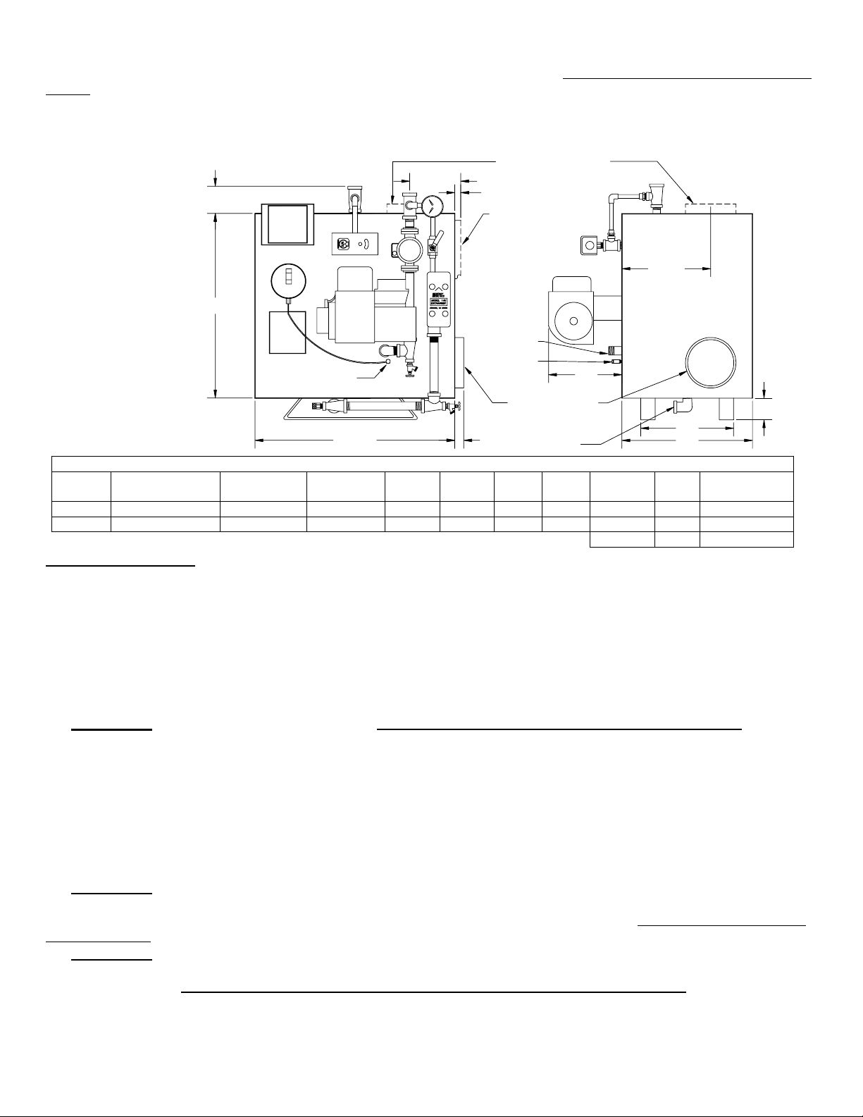
3 3/4"
5 1/4"
Vertical Flue Boiler
5" Flue (EK-1)
7" Flue (EK-2)
3/4"
Jacket Extension
Vertical Flue Only
Figure 1
Dimension
24 1/8"
Drawing
"D" Supply
Sample Port
Sample Port
1/4" Below Supply Pipe
24 1/8"
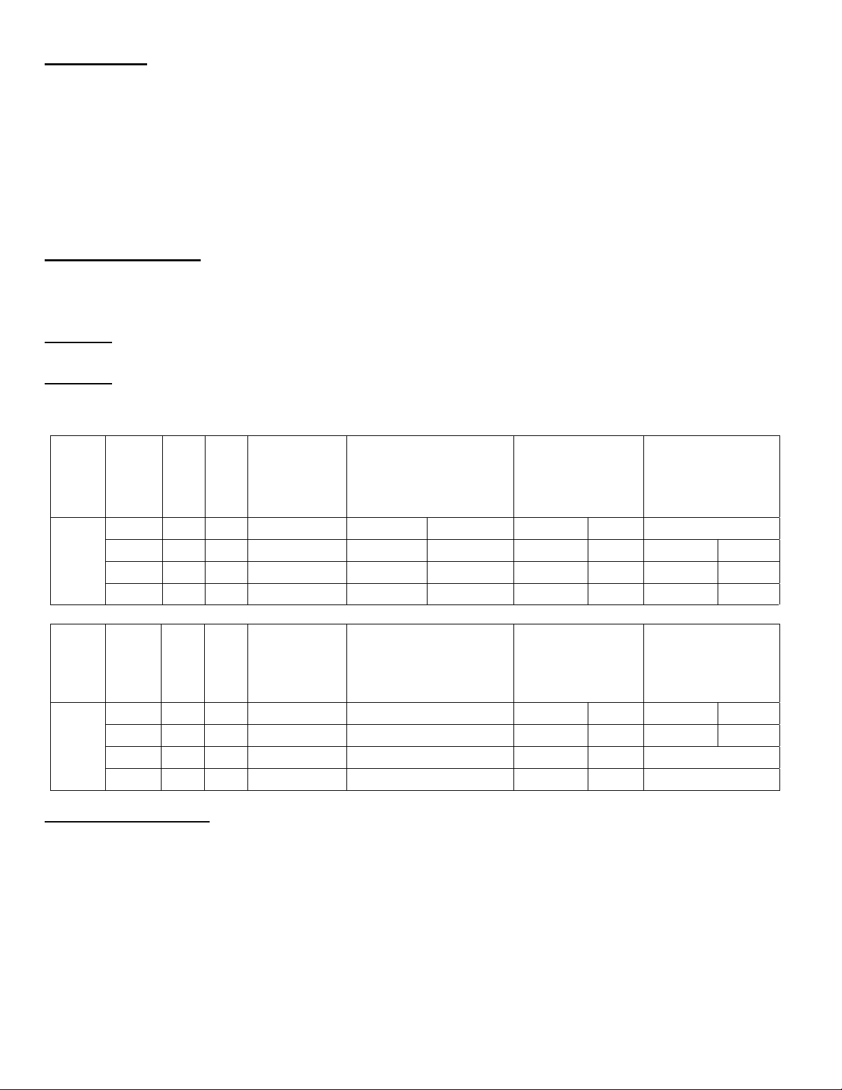
Clearances, Water Content, Weight, and Air Inlet Dimensions
Model Water Content Weight Lbs
EK1 2 ½ gal. 250 2" 17 ½” 13” 2 ½” 1” Beckett 11” 13”
EK2 4 gal. 350 3" 24 ¾” 20 ¼” 3 ½” 1 ¼” Carlin 14” 15 ½”
Riello 13” 13”
Air Inlet
Pipe Size
A
B
Side Flue Boiler
5" Flue (EK-1)
7" Flue (EK-2)
1"
"D" Return
C
"E"
D
Burner
9 1/4"
"C"
"B"
"A"
E E With Air Box
COMBUSTION AIR
The System 2000 Boiler must be installed in an area where adequate fresh air is available to support combustion. The
Frontier is provided with a sealed Air Box that can be piped to air outside the building. Piping of outside air directly to the
boiler is highly recommended because it completely isolates the boiler from the home environment, as well as greatly
reducing operating noise from the boiler.
Boiler with outside air piping:
In modern houses with tight construction, the connection of the Air Box to an outside air source to provide combustion
air is highly recommended. The outside air source must be located high enough above grade to be at least 12” above
expected snow accumulation.
WARNING: For systems with sidewall venting, combustion air piping from outside the building is required. The
Energy Kinetics sidewall vent kit contains specific instructions for installation that must be followed. Combustion air may be
supplied through PVC pipe. For EK1 use, 2" pipe up to 20 feet in length with up to (5) 90-degree elbows. For EK2 use, 3"
pipe up to 20 feet in length with up to (5) 90-degree elbows. A total equivalent length of 45 feet is allowed. Each 90 degree
elbow is the equivalent of 5 feet of straight pipe. For example, if three 90 degree elbows are used, then the length of pipe
run may increase to 35 feet. For longer runs up to 40 feet with up to five 90 degree elbows, immediately increase pipe size
by 1", to 3" for EK1 and 4" for EK2. An unglued or Tek-screw joint allows the door to swing down when the air inlet pipe is
disconnected.
Boiler without outside air piping:
WARNING: The confined space shall be provided with two permanent openings, one near the top of the enclosure
and one near the bottom. Each opening shall have a free area of not less than one square inch per 1,000 BTU per hour of
the total input rating of all appliances in the enclosure, freely communicating with interior areas having adequate infiltration
from the outside.
WARNING: Modern buildings of tight construction, as well as the operation of attic and exhaust fans, kitchen
ventilation systems, clothes dryers or fireplaces may create conditions of unsatisfactory combustion or venting. Provisions
must be made to use combustion air that communicates with a well-ventilated attic or with the outdoors
louver or grate). The opening should have a free area of not less than one (1) square inch per 4,000 BTU per hour of the
total input rating.
(such as using a
Twenty Ninth Edition – July 2005 6

CHIMNEY VENTING:
WARNING: Masonry chimneys must have a tile or metal liner. The liner must:
1) Extend above the masonry.
2) Have an insulating air gap, isolating the liner from the chimney, allowing for rapid heat-up and draft establishment.
3) Be sealed at each joint to prevent air infiltration and damage from condensation.
NOTICE: Inspect Chimney and Chimney base after initial three months of heating season.
The installation of a chimney cap is recommended. The base of the chimney must always have a drop leg below the
flue connector to allow scale and condensation to accumulate without blocking the flue pipe.
depth. All clean out doors must be sealed to prevent cold air entry into chimney.
CAUTION:
If drop leg is in excess of 12 inches deep, backfill with loose gravel or sand to obtain a maximum of 12-inch
In retrofit installations, have chimney thoroughly cleaned. Carefully inspect chimney, base of chimney, and liner prior to
installation of System 2000 Boiler.
CAUTION:
found at the base of the chimney, then it is recommended to install a properly sized metal liner approved for use with oil
heat appliances.
The metal liner diameter and length should be as recommended by the metal liner manufacturer. Corrugated metal
liners should be at least 5" diameter for EK1 and 6" diameter for EK2. Connection of a flexible metal liner directly to the flue
collar of the boiler is an acceptable connection method and is recommended. Energy Kinetics does not recommend use of
a base tee when a corrugated metal liner is installed. Alternatively, a flexible metal vent connector may be used between
the flue collar of the boiler and a flexible metal liner. Call Energy Kinetics for details on metal liners.
Chimney connectors should be positioned to create the shortest possible run of flue pipe to the chimney. The overall
horizontal length of flue piping should not exceed 15 feet. Long runs or low firing rates may require insulated flue pipe such
as L-Vent or All-Fuels to keep the temperature at base of chimney adequate for draft and to prevent corrosion of piping and
connectors.
Because the System 2000 boiler uses a power burner, the flue pipe may experience some positive pressure on start
up. Energy Kinetics recommends that all pipe joints be sealed with high temperature silicone sealant to ensure passage of
all combustion products to the chimney.
Normally, pitch horizontal flue pipe up toward chimney approximately ¼” per foot. For existing installations, it is
permissible for the flue connection of the boiler to be higher than the chimney thimble, provided adequate draft is
established.
If a minimum of -0.02” w.c. draft overfire is not present after sufficient burner run time to heat up the chimney, there is a
problem that will need to be corrected. Call Energy Kinetics for help resolving draft problems. Under normal
circumstances, there is NO need for a DRAFT REGULATOR
questions about flue pipe sizing.
WARNING:
flue gas exit of the venting system must be at least three (3) feet above the point at which it passes through the roof and at
least two (2) feet higher than any portion of a building within 10 feet horizontally of its location.
L-Vent Chimney:
SYSTEM 2000 Boilers typically have flue gas temperatures between 350F and 450F during normal operation. Due to
the low flue gas temperatures, L-Vent chimney pipe is suitable for use with SYSTEM 2000 Boilers. L-Vent chimney pipe
may require smaller chase dimensions than other chimney pipe materials and should be considered for new installations
with SYSTEM 2000 Boilers. Call Energy Kinetics for help locating sources of L-Vent.
1. L-Vent must be U.L. Listed to U.L. 641.
2. L-Vent to be installed in accordance with the vent manufacturer’s instructions.
3. System 2000 and L-Vent must be installed in strict compliance with all State and Local Codes and with the regulations of
the authorities having jurisdiction, which may differ from and which take precedence over these instructions or the vent
manufacturer’s instructions.
Sidewall Venting:
1. System 2000 Boilers may be installed with Energy Kinetics' sidewall vent kit in accordance with kit instructions.
2. WARNING:
hood must be located on the same side of the structure.
3. NOTICE: The sidewall vent inducer should be located above the boiler flue outlet, preferably a minimum of four feet
vertical distance, which will provide some natural draft to the boiler (and cooling of the burner) in case of a power failure.
4. When installing a sidewall venting system from another manufacturer, ensure that the manufacturer’s instructions are
followed. Vent manufacturer should confirm that the equipment is suitable for use with System 2000.
5. Set the draft over fire through the puff switch opening between -.10" to -.12" w.c. with the burner running, after allowing
time for sufficient warm-up. Check/adjust CO
6. To provide power to the sidewall vent, install the plug-in relay supplied with the sidewall vent kit into the junction box
relay board and set the Digital Manager Option Switch #2 to the “ON” (down) position. This enables the “Inducer” light
and allows the Digital Manager to control the inducer. Refer to Digital Manager section for option switch settings and
inducer timing details.
If liner is not sound, or if existing tile liner fails to contain intermittent condensation, or if excessive debris is
and one should not be installed. Call Energy Kinetics with
No solid fuel appliance or fireplace should be installed in a flue common with this heating appliance. The
Sidewall vent systems must have outside air connected to the air box and both air box air intake and vent
. Re-check the draft over fire and adjust draft if necessary.
2
Twenty Ninth Edition – July 2005 7
Fuel System:
NOTICE: Inspect and if needed, replace oil lines according to local codes. Oil lines must be absolutely airtight. Use
only flared joints on all copper tubing and use thread sealant suitable for oil on all iron pipe threaded joints. Do not use
teflon tape on fuel system joints. Check all joints and connections for leaks after installation. A high quality fuel filter should
be installed in the fuel line. Energy Kinetics’ “Smart Filter” or equivalent 10-micron filter is recommended. When changing
the Smart Filter, be sure to lubricate cartridge gasket with motor oil, not heating oil.
All piping systems should conform with pump manufacturer’s specifications that are attached to each new pump. The
burner is capable of burning No. 1 or No. 2 heating oil. A fusible link shutoff valve should be installed on the supply line.
NOTICE: A two-stage pump is required if lift from oil tank exceeds approximately ten (10) feet. Follow instructions
provided by pump manufacturer on single and two pipe connections for bypass plug usage and other specific installation
requirements.
Oil Burner Settings:
EK1 Boilers are shipped from the factory preset for 0.85 GPH firing rate and EK2 Boilers are shipped from the factory
preset for 1.40 GPH firing rate. The SYSTEM 2000 Boiler can be fired over a range of firing rates to suit the needs of the
application. The following table lists approximate settings for oil burners based on testing performed at Energy Kinetics.
CAUTION: Final settings for each burner and firing rate for a particular installation must be determined by using
combustion test equipment and following the instructions given under "Start Up Procedure".
CAUTION: Because the energy converter removes heat from the combustion flue gas so efficiently, low firing rates may
not provide high enough flue gas temperature for proper draft in a chimney. The Columns labeled 'Chimney' and 'Sidewall'
show the suitability of the firing rate for a particular combination.
Carlin 99FRD
Single Slot Air
band
Delavan 60°A
Riello 40F5
Delavan 60°B
Model
Input
GPH
Chimney
Sidewall
Vent
Nozzle@
Pump
Pressure
Beckett AFG
Delavan 70°A
1
.68 N Y .60@130 psi Air band: 0 Shutter: 4 Head: 1.0 Air: 25 Not Recommended
EK1
.74 N Y .65@130 psi Air band: 0 Shutter: 5.5 Head: 1.0 Air: 35 Head: 1.0 Air: 2.25
.85 * Y Y .75@130 psi Air band: 0 Shutter: 7 Head: 1.5 Air: 45 Head: 1.5 Air: 2.5
1.0 Y Y .85@136 psi Air band: 1 Shutter: 8 Head: 2.5 Air: 60 Head: 2.0 Air: 2.75
1
the Beckett AFG at 0.68 gph firing rate can be retrofitted with the Beckett Low Firing Rate Baffle. If used, set air band: 0, shutter: 8.5.
Carlin 99FRD
Dual Slot Air band
Delavan 60°B
Riello 40F5
Delavan 60°A
Model
Input
GPH
Sidewall
Chimney
Vent
Nozzle@
Pump
Pressure
Beckett AFG
1.20 N Y 1.00@145 psi Not Recommended Head: 2.5 Air: 55 Head: 3.0 Air: 3.5
EK2
1.40 * Y Y 1.25@125 psi Not Recommended Head: 3.0 Air: 55 Head: 3.5 Air: 5.5
1.60 Y Y 1.35@140 psi Not Recommended Head: 4.0 Air: 60 Not Recommended
1.75 Y N 1.50@135 psi Not Recommended Head: 4.5 Air: 80 Not Recommended
* Factory Setting
Oil Burner Mounting:
SYSTEM 2000 Boilers are shipped from the factory with the oil burner pre-mounted. The burner flanges are designed
to insert the burner head 2-3/8” into the boiler. Energy Kinetics installs a ceramic sleeve, (the amulet), to protect the burner
head from the heat of combustion, and then seals the air tube flange joint with a high-grade retort cement. NOTICE: Oil
burners for field installation or for field replacement should be installed according to burner manufacturer instructions,
according to installation instructions below, and with consultation with Energy Kinetics for any special considerations or
adjustments.
Follow these instructions for field installation of Energy Kinetics supplied burners. Start by checking nozzle and
electrode position per manufacturer’s specifications prior to assembly to unit. Test fit the amulet by inserting the amulet into
the boiler opening. If the amulet doesn't easily slide into the boiler, then gently sand the outside diameter of the amulet until
it will fit into the boiler opening. Test fit the amulet onto the burner head. Note that the amulet designed for the Beckett
AFG burner has interior slots to accept the screws on the sides of the head. The amulet for the Beckett AFG has a small
drain hole in the front face, that must be mounted at the bottom (at 6 o'clock position). The amulet for the Carlin and Riello
Twenty Ninth Edition – July 2005 8
 Loading...