

ENERGY KINETICS 90+RESOLUTE BOILER, System 2000, EK2 Frontier, EK1 Frontier Owners And Installation Manual
UL Energy Verified, your
trusted alternative to
AFUE industry listings.
National Board
Listed
90+RESOLUTE
OWNER AND INSTALLATION MANUAL
.
MH28303
UL 726;
CAN/CSA-B140.7-05
CAN/CSA-B140.0-03
CAN/CSA-B139-M91
Low-Press Boiler
INSTALLER: HANG THIS INSTRUCTION MANUAL AND ACCESSORY INSTRUCTIONS VISIBLY
HOMEOWNER/USER: READ AND SAVE THIS INSTRUCTION MANUAL AND ACCESSORY INSTRUCTIONS
Resolute Oil Heat – PN 10-2025 – July 2018
Energy Kinetics, Inc.
NEXT TO THE BOILER USING THE SUPPLIED POUCH.
FOR FUTURE REFERENCE.
TM
BOILER
OILHEAT EDITION
Manufactured By:
51 Molasses Hill Road
Lebanon, NJ 08833
(908) 735-2066
www.energykinetics.com
ASME certified by EKI.
Certificate plate is under
the jacket on the steel
vessel.

Please Read This First…..
Special Attention Flags
Please pay particular attention to the following flags when you see them throughout this manual.
DANGER: Notifies you of hazards that WILL cause severe personal injury, death or substantial property damage.
WARNING: Notifies you of hazards that CAN cause severe personal injury, death or substantial property damage.
CAUTION: Notifies you of hazards that WILL or CAN cause minor personal injury or property damage.
NOTICE: Notifies you of special instructions on installation, operation, or maintenance that are important, but not
normally related to injury or property damage hazards.
WARNING: Retain this manual for use by your qualified service technician only. Should you observe unusual or
abnormal operation of the burner or boiler, contact your qualified service technician immediately. Do
not attempt to service or repair this product yourself.
WARNING:
WARNING:
Have the burner/boiler started up and serviced at least once annually by a qualified service
technician. Professional care is necessary to properly service your equipment and verify it is
operating reliably. Failure to properly maintain the equipment could result in severe personal injury,
death or substantial property damage.
You must keep the area around the burner/boiler free from the following. Failure to comply could
result in severe personal injury, death or substantial property damage due to potential fire, explosion
or equipment damage from corrosive flue products.
Do not store or use gasoline or other flammable vapors or liquids near or in the same room
as the burner.
Do not use or store laundry products, paint, varnish, thinner or other such chemicals near or
in the same room as the burner/boiler. These chemicals cause creation of acids in the
burner, heat exchanger and vent system that can cause severe damage.
Do not store combustible materials near or in the same room as the this boiler
combustion appliance.
CAUTION:
WARNING:
DO NOT TAMPER WITH THE UNIT OR CONTROLS – CALL YOUR SERVICE PERSONNEL.
Improper installation, adjustment, alteration, service or maintenance can cause property damage,
personal injury (exposure to hazardous materials) or loss of life. Refer to the user’s information
manual provided with this boiler. Installation and service must be performed by a qualified installer,
service agency or the gas supplier (who must read and follow the supplied instructions before
installing, servicing, or removing this boiler. This boiler contains materials that have been identified
as carcinogenic, or possibly carcinogenic, to humans).
Homeowner/User: General care and maintenance of your boiler:
Please read through the information provided for you in this manual. Ask your qualified service technician to
explain normal operation of your equipment.
Daily inspect the space around the burner/boiler to verify the area is clean and free of the materials listed
above.
Monthly watch the operation of your burner/boiler through an operating cycle to verify normal operation. If
you notice unusual conditions or equipment behavior, contact your qualified service technician. Follow the
instructions on the next page to shut down the burner/boiler while waiting for the technician.
or any other
Resolute Oil Heat – PN 10-2025 – July 2018 2

TABLE OF CONTENTS
Page Topic Page Topic
2 Please read this first 14 Install Energy Manager
3 Table of Contents 15 Five Zone Display Manager
4 Homeowner/User Note 15 How to Use Self-Guided On-Screen Prompts to
Edit Options
5 Record of Installation 16 Dip Switch Settings
6 SYSTEM 2000 Boiler - Principle of Operation 16 Display Manager Option Menu Descriptions
6 Energy Manager - Principle of Operation 17 Expanded Energy Manager
7 Receiving and Unpacking 17 15 Zone Manager Installation Instructions
7 Location and Clearance 18 Hydronic Control Settings
Boiler Weight, Water Content, Inlet and Outlet Sizes
7
8 Clearance for Cleaning and Service 18 Start Up Procedure
8 Smart Vent System 19 Oil Burner Operation and Safety Checks
9 Fuel Systems 19 Oil Burner Operation
9 Oil Burner Settings 21 Digital Energy Manager Check
9 Oil Burner Mounting 22 2 Minute Diagnostics
10 General Assembly 23 Additional Tests
10 Boiler Mounting 24 Display Mana ger Return Sensor Testing
11 Piping 24 Line Voltage Relays
12 Zone Control 24 Surge Suppression
12 Boiler Bypass Line and Valve 25 Troubleshooting with Energy Manager
12 Filling with Water, Venting, and Purging 26 Operation without the Energy Manager
12 Boiler Water Treatment 26 Emergency Heat Without Energy Manager or
12 Anti-Freeze 27 Annual Tune Up & Inspection
13 Winterizing 29 Replacement Parts
13 Line Voltage Wiring and Diagram 29 Amulet Replacement
13 Wiring and Controls 29 Combustion Chamber Replacement
14 Electrical Connection - Line Voltage 30 Replacement Parts Ordering
14 Low Voltage Wiring and Diagram
Inside
Back
Warranty Transfer Agreement
Cover
18 Prepare for Start-Up
Relay Board
Rear
Cover
Limited Lifetime Warranty
Resolute Oil Heat – PN 10-2025 – July 2018 3

HOMEOWNER/USER NOTE:
EMERGENCY SHUT DOWN INSTRUCTIONS:
Turn power off to boiler by switching the “Oil Burner Emergency Switch” (typically located at the top of basement
stairway or at boiler room entrance) to the OFF position. If unable to locate the “Oil Burner Emergency Switch” then
switch the “System Emergency Switch” located at the boiler, on the left hand side of the system junction box located on
the top left hand side of the boiler. Shut off oil supply valve.
NOTICE
Do not use this boiler if any part has been under water. Immediately call a qualified service technician to inspect
the boiler and to replace any part of the control system which has been under water.
IN CASE OF NO HEAT
In case of no heat coming from the boiler, perform the following actions or call a qualified service agency for help.
Look at the Energy Manager and write down all lights showing on the Energy Manager.
o Refer to the Energy Manager Operation Summary for the meaning of the lights.
o Reset the Energy Manager by turning off and back on the System Switch on the left side of the Manager.
Remove the burner cover and look at the LEDs on the burner control. If the red LED is on constantly, then press
and hold in the reset button for one second. The burner will then try to relight. If the burner relights successfully,
then no further action is needed.
If the burner goes into lock out again, contact a qualified service agency for help.
ANNUAL MAINTENANCE
The SYSTEM 2000 boiler requires an annual tune-up by a qualified service agency to maintain top efficiency and peak
performance and to verify proper performance of all safety devices.
PERIODIC MAINTENANCE
The SYSTEM 2000 boiler requires minimal attention from the user.
- Daily inspect the space around the burner/boiler to verify the area is clean and free of any flammable or combustible
materials.
- Once a month it is recommended that the owner/user inspect the boiler and to watch the operation of the boiler. The
owner/user should:
Inspect flue connections.
o Look for evidence of deterioration from corrosion or other sources. Watch the flue pipes during a start up of
the boiler and look and smell for evidence of escaping flue products.
Inspect for evidence of water, such as leakage from the safety pressure relief valve.
Watch the Energy Manager during one heating cycle of the boiler.
Verify the pressure gauge on the boiler is reading between 5 psi and 30 psi.
Verify the temperature gauge on the boiler reads no more than 220F at the end of a heating call.
If any of the above items seem unusual or out of the ordinary, then immediately call your qualified service agency.
Resolute Oil Heat – PN 10-2025 – July 2018 4

RECORD OF INSTALLATION
INSTALLER NAME:
INSTALLER ADDRESS:
INSTALLER CITY, STATE:
DATE INSTALLED:
NOTES:
SCOPE
This manual covers the Energy Kinetics System 2000 Resolute Boiler. The boiler is designed and equipped and has
been tested to generate hot water in a low pressure closed loop system. The boiler is a major component of a closed loop
system that can be used as a heat source for hydronic, radiant, domestic hot water, spa, and/or pool heating systems.
Call Energy Kinetics to obtain piping and wiring instructions for applications, such as hydronic heating, radiant heating,
domestic hot water, swimming pool heating, multiple boilers, injection loops, etc. The installer of the system is
responsible for the final design of the system and for adding the balance of the needed parts to complete the system.
COMMONWEALTH OF MASSACHUSETTS
When the boiler is installed within the Commonwealth of Massachusetts:
This product must be installed by a licensed plumber
If antifreeze is used, a reduced pressure backflow preventer device shall be used
INSTALLER NOTE:
ALL INSTALLATIONS MUST BE MADE IN ACCORDANCE WITH ALL NATIONAL, STATE AND LOCAL,
PLUMBING, HEATING AND ELECTRICAL CODES THAT MAY DIFFER FROM THIS MANUAL AND IN
ACCORDANCE WITH THE FOLLOWING CODES, AS APPLICABLE:
N.F.P.A. No. 70: National Electrical Code
Canadian Electrical Code, Part I
A.N.S.I. / N.F.P.A. No. 211: Chimneys, Fireplaces, Vents and Solid Fuel Burning Appliances
A.N.S.I. / N.F.P.A. No. 31: Installation of Oil Burning Equipment
If this oil fired boiler is converted to gas fired by field mounting a listed gas conversion burner, then install in
accordance with A.N.S.I. Z223.1/N.F.P.A. No. 54: National Fuel Gas Code
These codes are available from:
National Fire Protection Association
1 Batterymarch Park
Quincy, MA 02269-9101.
A hot water boiler installed above radiation level or as required by the Authority having jurisdiction, must be
provided with a low water cutoff device.
A boiler should be installed in such a manner that, if the pressure vessel or any connection thereto should leak,
the resulting flow of water will not cause damage to the area in which it is installed.
A hot water storage tank should be installed in such a manner that, if the storage tank or any connection thereto
should leak, the resulting flow of water will not cause damage to the area in which it is installed.
A boiler’s pressure relief valve, hot water storage tank T&P relief valve, backflow preventer, and all other
devices must be piped to the nearest drain to avoid damage in the event the valve is actuated.
Make sure relief discharge pipes from all reliefs are properly placed to safely contain discharge. Make sure
relief discharge pipes, such as from a boiler or a hot water storage tank, will safely contain hot water and/or
boiling water. Make sure relief discharge pipes, such as from a boiler or a radiant heating system, will safely
contain water treated with boiler chemicals and/or antifreeze. Reliefs include the boiler pressure relief valve, the
back flow preventer discharge port, and the domestic hot water tank temperature and p ressure relief valve. Any
other reliefs, such as from radiant heating systems, must also follow these guidelines.
Resolute Oil Heat – PN 10-2025 – July 2018 5

SYSTEM 2000® RESOLUTE® BOILER
IMPORTANT MESSAGE TO HOMEOWNER/USER: These instructions should be carefully read and kept for future
reference to gain the best performance from your System 2000 Resolute boiler.
CONGRATULATIONS ON YOUR PURCHASE OF THE SYSTEM 2000 RESOLUTE BOILER with its highly efficient
low mass hydronic heat exchanger, the Energy Converter. It is the product of years of engineering and advanced design,
which brings together in a single system all elements needed to provide efficient home heat and hot water. This operation
and maintenance information has been prepared so that you may better understand and use your Energy Kinetics
Resolute Boiler and Heating System.
SYSTEM 2000 BOILER - PRINCIPLE OF OPERATION
SYSTEM 2000 comprises a heat source, the energy converter, circulating water, and five (or more) zones controlled
by an electronic control, the Energy Manager.
The Boiler sits cold until a thermostat calls for heat. The Energy manager receives the call for heat and turns on the
main circulator and burner. Water circulates within the boiler as it warms up to operating temperature. When ready, the
zone valves open and deliver heat to the zones calling for heat. When the thermostats are satisfied, the Energy Man ager
turns off the burner and enters the energy recovery stage. The circulator and zone valve stay energized to deliver the
heat remaining in the boiler to your home or to the domestic hot water storage tank.
When energy recovery is complete and the Boiler has been cooled off, the Energy Manager turns off the system and
waits for another thermostat (or tank aquastat) to call for heat. SYSTEM 2000 runs the burner only when you need heat
and delivers that heat only where you need heat.
The System 2000 Energy Converter is the product of advanced thermal engineering. It is designed with two separate
passageways, nearly 15 feet long, coiled around each other. Water travels along one passageway from your home
toward the center of the unit and heated gases travel from the unit center toward the chimney. This is a “forced circulation
counter-flow” design and it provides very efficient transfer of heat from the burning fuel to the circulating water. The
superior insulation of the boiler minimizes heat losses to the surroundings, resulting in dire cting heat to your home in an
efficient and quiet manner.
SYSTEM 2000 has an extremely high annual efficiency (over 95% of steady state) because it runs only when your
home or hot water storage tank needs heat. Energy recovery is completed at the end of each heat call, virtually
eliminating off cycle losses.
Your System 2000 holds a minimal quantity of water so it begins to supply heat in about 2 minutes. This rapid
response means that your rooms can be heated quickly when cold. The System 2000 EK1 Resolute can also provide
heating of domestic water just as quickly.
A modern retention head oil burner fires into the center of System 2000 where a high temperature, light weight
ceramic chamber provides ideal conditions for “near perfect” efficient, pollution-free co mbustion. Your System 2000 is
tightly sealed so all products of combustion pass only to the sidewall Smart Vent.
The RESOLUTE Boiler is designed with a hinged front cover that allows access to the inside of the boiler for
inspection and cleaning. All access for service is from the front, so the RESOLUTE Boiler can be placed against a wall or
into a closet.
ENERGY MANAGER - PRINCIPLE OF OPERATION
The left side of the Manager is the input side, which provides 24-volt power supply and connections for thermostats.
The right side is the output side, which starts the burner, circulator, zone valves or zone circulators and the domestic hot
water circulator. See photo of the Manager on the cover.
Lights on the Energy Manager indicate what is calling for heat (left side) and (right side) light s indicate active zone(s),
burner operation and circulator operation. These function lights are an aid in servicing. The following is a typical cycle.
1. SYSTEM WAITING FOR A CALL: The boiler is turned off and sits cold, waiting until a call for heat. The red power
light on the Manager is glowing.
2. CALL FOR HEAT: A room thermostat call starts the cycle. The thermostat light on the left side will turn on for that
zone.
3. PRE-HEAT: Output lights for the main circulator and burner turn on, the circulator starts, and the burner begins firing.
The boiler water circulates through the energy converter via the bypass line, heating up the water.
4. HEAT: Once the boiler water has heated to 140F (about 90 seconds), the Manager will turn on the zone output light
on the right side. The zone valve will open and hot water will flow to the zone needing heat. The burner runs as long
as there is a thermostat calling and as long as heat is being delivered to the zone. The burner may shut off if the
return temperature exceeds 170F/190F (RED burner light turns off) or if the high limit temperature is excee ded (RED
burner light stays on, but the high limit aquastat shuts the burner off).
5. ANOTHER CALL FOR HEAT: If another zone calls for heat while the burner is already running and the return
temperature is above 140F, the zone output will turn on, immediately supplying heat to the zone.
Resolute Oil Heat – PN 10-2025 – July 2018 6
6. MONITOR RETURN TEMPERATURE: The Manager continually senses the return temperature and will turn off the
zone outputs if the return temperature drops below 120
closed, the boiler water will quickly reheat and once the return temperature reaches 140
o
F (130o F if Option Switch #1 is ON). With the zone outputs
o
F (150o F if Option Switch
#1 is ON), then the Manager will reopen the zone valves.
7. THERMOSTAT SATISFIED: The thermostat light on the left side will go out. The burner light and the burner will then
turn off.
8. ENERGY RECOVERY: The circulator and zone valve remain energized. The circulating water will remove the energy
from the converter, sending the heat to the last zone that called. The energy recovery stage continues until the return
temperature has dropped sufficiently or until maximum timing has been reached. The boiler is now sitting cold,
waiting for the next call for heat. Maximum timing for heat recovery stage is usually set at twenty minutes for space
heating zones and is fixed at five minutes for the Hot Water zone. (See Energy Manager Option Switch Settings).
RECEIVING and UNPACKING
Inspect shipment upon receipt for external damage. When unpacking and uncra t ing, inspect each item for internal
damage. Any damage found should immediately be reported to the freight carrier before installation. The receiver is
responsible for following the claims procedure of the freight carrier. The freight carrier is responsi ble for taking prompt
action on all claims. If freight cannot be inspected at the time of delivery, sign the bill of lading “Subject to Inspection” and
inspect the shipment as soon as possible after receipt. Replacements for parts damaged in shipment are a v ailable upon
receipt of a signed copy of a claim report (concealed damage claims should be filed imm ediately against the freight carrier
by the consignee).
After unpacking, check each item again st the packin g list. Inspect it thoroughly for loose parts, instru ction sheets and
packing lists. Immediately report any missing items. It is wise to complete the installation before discarding packing
material. Store all parts where they will not be damaged or lost during installation.
LOCATION and CLEARANCE
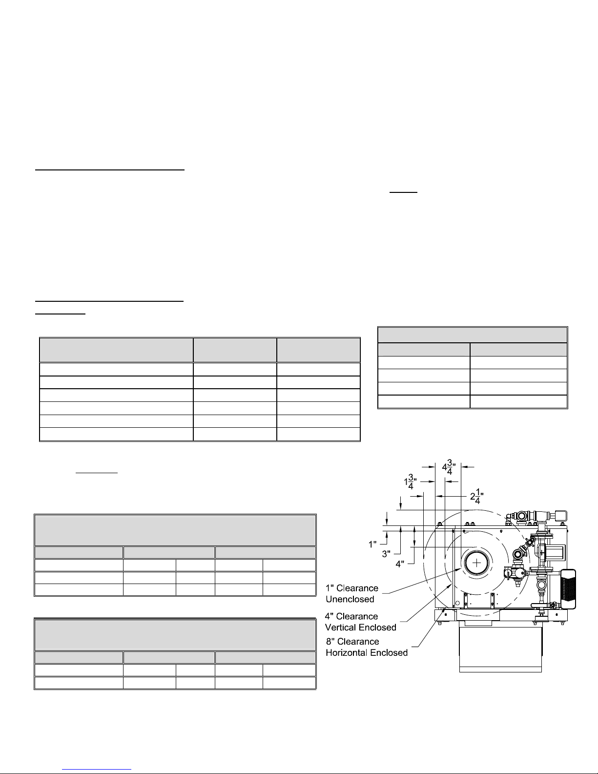
DANGER: Provide clearance to combustible surfa ces in accordance with all local and national codes. Follow National
Fire Protection Association Bulletin NFPA Installation of Oil Burning Equipment and all applicable codes.
Installation Clearances from
Boiler Surfaces, Inches
Clearance to
Combustibles
Clearance for
Service
Front of boiler 15 1/2 20
Left side of boiler body 0 0
Right side of boiler body 0 0
Back of boiler body 4 4
Top of boiler body 16 16
Bottom of boiler legs to floor 0 9*
* Minimum recommended clearance to allow door to fully open.
Figure 1A Top View of Boiler –
Flue Connection Clearance to Combustibles
Boiler Weight and Water Content
Model EK1 Resolute
Weight 270 lbs
Water Content 2-1/2 gallons
Air Inlet Pipe Size 2"
Boiler Flue Outlet 4"
Z-Flex Z-Vent III
Flue Connection/Pipe Clearance to Combustibles
Flue Gas Temp Clearance Enclosed Clearance Unenclosed
Horizontal Vertical Horizontal Vertical
300ºF 8” 4” 1” 1”
480ºF 8” 4” 1” 1”
For more information, see Z-Vent Model SVE Series III Installation and
Maintenance Instruction
CENTROTHERM
Flue Connection/Pipe Clearance to Combustibles
Flue Gas Temp Clearance Enclosed Clearance Unenclosed
Horizontal Vertical Horizontal Vertical
248ºF Max 0 0 0 0
For more information, see Centrotherm Installation Instructions
Resolute Oil Heat – PN 10-2025 – July 2018 7
Figure 1A
Resolute boilers come with a stand mounted at the factory which provides a convenient, solid, level and smooth
n
o
a
n
d
a
e
r
foundation for the boiler. Place the unit as near to the venting location as possible allowing clearance for front cleaning
and service as shown in Figure 1B
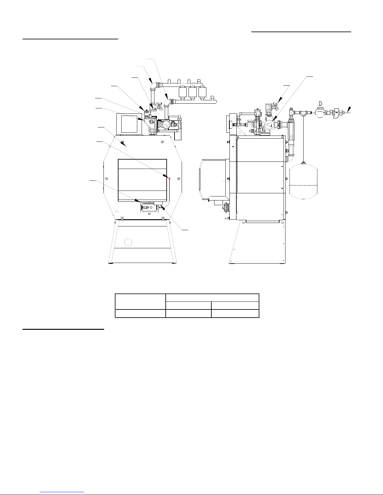
NOTICE: The stand must be level to slightly higher at the back, to allow for proper venting of air from the boiler.
Flue Box Test Port
Combustion/Over Fire
T&P Gauge
Return Manifold
Test Port
3/4" Air Vent
Relief Valve
Supply
Return
Zone Valves
Return Ball & Purge
System Ci
Feedwater
Connectio
Premier Opti
Auto Feed/B
Preventer
Blocked Vent (Puff)
Safety Switch
Expansio
be locate
piping or
side of th
Combustion
Air Inlet
Beckett AFG 8” 9-5/8"
* Note: Air box is required for Smart Vent operation.
Figure 1B* - Boiler Clearance for
Installation and Service
Burner
W/O Air box* With Air box
Dim “A”
SMART VENT SYSTEM
The Smart Vent with Dilution Air System is a complete vent system that has been specifically designed for use with
Energy Kinetics’ Resolute boiler. It uses a standard EK1 forced draft inducer fan and requires outside air for combustion
air. Each part of this system works together and must be installed properly to work correctly.
Starting with combustion air, outside air must be piped directly to the factory supplied pvc air inlet tee. The air inlet
tee is connected to the stainless steel dilution tee rated for positive pressure. The branch on the inlet tee is connected to
the sealed air box and provides combustion air using pvc pipe and elbows supplied.
The EK1 forced draft inducer fan is factory mounted directly to the dilution tee, which is mounted directly on the boiler
breech. The boiler pressure vessel is maintained at negative pressure by the forced draft fan. A fan proving safety switch
is wired in series with the burner motor. Power to the burner motor is interrupted if operation of the forced draft fan is not
proven. The system requires no draft adjustment when installed as recommended and is designed for use without any
draft damper.
Combustion air is piped from the branch of the dilution air tee to the PVC male adapter on the sealed air box frame.
Piping of outside air directly to the boiler is required to ensure that adequate fresh air is available for combustion and
proper dilution of flue gasses. It completely isolates the boiler from the home environment, as well as greatly reducing
operating noise from the boiler. A blocked air intake safety switch is wired in series with the standard System 2000
blocked vent switch. Burner operation will be prevented if the air inlet is blocked or if the boiler flue passage is blocked.
The Resolute boiler Smart Vent with dilution air system includes the System 2000 sidewall vent termination. The
Smart Vent system for the Resolute boiler must be installed according to the Smart Vent with Dilution Air installation
manual.
Resolute Oil Heat – PN 10-2025 – July 2018 8

WARNING: Sidewall venting and combustion air piping from outside the building is required. The Energy
Kinetics Smart Vent kit contains specific instructions for installation that must be followed. For length of run for intake air
and for the vent connection, refer to the Smart Vent with Dilution Air installation manual. Combustion air may be supplied
through PVC pipe. An unglued or Tek-screw joint allows the door to swing down when the air inlet pipe is disconnected.
FUEL SYSTEMS
NOTICE: Inspect and if needed, replace oil lines according to local codes. Oil lines must be absolutely airtight. Use only
flared joints on all copper tubing and use thread sealant suitable for oil on all iron pipe threaded joints. Do not use Teflon
tape on fuel system joints. Check all joints and connections for leaks after installation. A high quality fuel filter should be
installed in the fuel line. A high quality UL Listed 10-micron fuel filter is recommended. When changing the fuel filter, be
sure to lubricate cartridge gasket with motor oil, not heating oil.
Resolute boilers must be equipped with a fuel filter and a flexible fuel line. Call Energy Kinetics to obtain optional UL
Listed fuel filter and optional UL Listed flexible fuel line. The flexible fuel line allows the door to open without
disconnecting the fuel supply. The flexible line connects the fuel pump to the Smart Filter. The fuel filter can be mounted
on the left-hand side of the base. A fusible link shutoff valve should be installed at the inlet of the fuel filter or as required
by the authority having jurisdiction. If the oil supply is higher than the burner, then an anti-siphon valve (OSV) should be
installed.
All piping systems should conform with pump manufacturer’s specifications that are attached to each new pump. The
burner is capable of burning No. 1 or No. 2 heating oil.
CAUTION: DO NOT USE GASOLINE, CRANKCASE DRAININGS, OR ANY OIL CONTAINING GASOLINE.
NOTICE: Order an additional flexible fuel line for two-pipe systems. A two-stage pump is required if lift from oil tank
exceeds approximately ten (10) feet. Follow instructions provided by pump manufacturer on single and two pipe
connections for bypass plug usage and other specific installation requirements.
CAUTION: ALWAYS KEEP THE OIL SUPPLY VALVE SHUT OFF IF THE BURNER IS SHUT DOWN FOR AN
EXTENDED PERIOD OF TIME.
OIL BURNER SETTINGS
EK1 Resolute Boilers are shipped from the factory preset for 0.74 GPH firing rate. The following table lists
approximate settings for oil burners based on testing performed at Energy Kinetics.
CAUTION: Final settings for each burner and firing rate for a particular installation must be determined by using
combustion test equipment and following the instructions given under "Start Up Procedure".
CAUTION: Because the energy converter removes heat from the combustion flue gas so efficiently, flue gas
temperatures will not be high enough for proper draft in a chimney.
Beckett AFG1
130 psi 0 4
130 psi 0 5.5
Model
Input
GPH
.68
.74
Nozzle Delavan
.60 70A
.65 70A
Pump Pressure Air Band Air Shutter
EK1
.85 *
1.0
1
the Beckett AFG at 0.68 gph firing rate can be retrofitted with the Beckett Low Firing Rate Baffle. If used, set air band: 0, shutter: 8.5.
.75 70A
.85 70A
130 psi 0 7
136 psi 1 8
OIL BURNER MOUNTING
Resolute Boilers are shipped from the factory with the oil burner pre-mounted. The burne r flange is designed to insert
the burner head 2-3/8” into the boiler. Energy Kinetics installs a ceramic sleeve (the amulet), to protect the burner head
from the heat of combustion, and then seals the air tube flange joint with a high grade retort cement.
NOTICE: Oil burners for field installation or for field replacement should be installed according to burner
manufacturer instructions, according to installation instructions below, and with consultation with Energy Kinetics for any
special considerations or adjustments.
Follow these instructions for field installation of Energy Kinetics supplied burners. Start by checking nozzle and
electrode position per manufacturer’s specifications prior to assembly to unit. Test fit the amulet by inserting the amulet
into the boiler opening. If the amulet doesn't easily slide into the boiler, then gently sand the outside diameter of the
amulet until it will fit into the boiler opening. Test fit the amulet onto the burner head. Note that the amulet designed for
the Beckett AFG burner has interior slots to accept the screws on the sides of the head. The amulet for the Beckett AFG
Resolute Oil Heat – PN 10-2025 – July 2018 9
has a small drain hole in the front face, which must be mounted at the bottom (at 6 o'clock position). If the amulet is a
tight fit on the burner head, then slightly moisten inside the amulet with water.
Place a 3/8" bead of retort cement onto the burner head at the flange to air tube joint, and slide the (moistened)
amulet over the burner head and against the flange. Ensure proper seating of the amulet by pressing the amulet onto the
burner with a flat object. Leave the excess retort cement at the amulet to flange joint and the cement will provide an
airtight seal of the air tube flange to the boiler face.
The Beckett amulet has an inside edge that will cover the edge of the Beckett burner head. The Beckett retention
head air slots must not be blocked or obstructed by the amulet. If needed, trim a 45 degree chamfer on the inside of the
amulet using a sharp utility knife and maintain a 1/8" clearance to retention head air slots.
with amulet into the boiler opening while aligning the burner flange holes with the boiler studs. Install flat washers and
nuts onto the boiler studs and tighten all nuts evenly.
Once the amulet has been seated and trimmed, then install the burner into the boiler by carefully inserting the air tube
GENERAL ASSEMBLY
Assembly of various packaged units is illustrated throughout this manual. The use of non-Energy Kinetics supplied
pump, controls and accessories should follow good practices. The diagrams and locations presented in the manual are
recommended.
BOILER MOUNTING
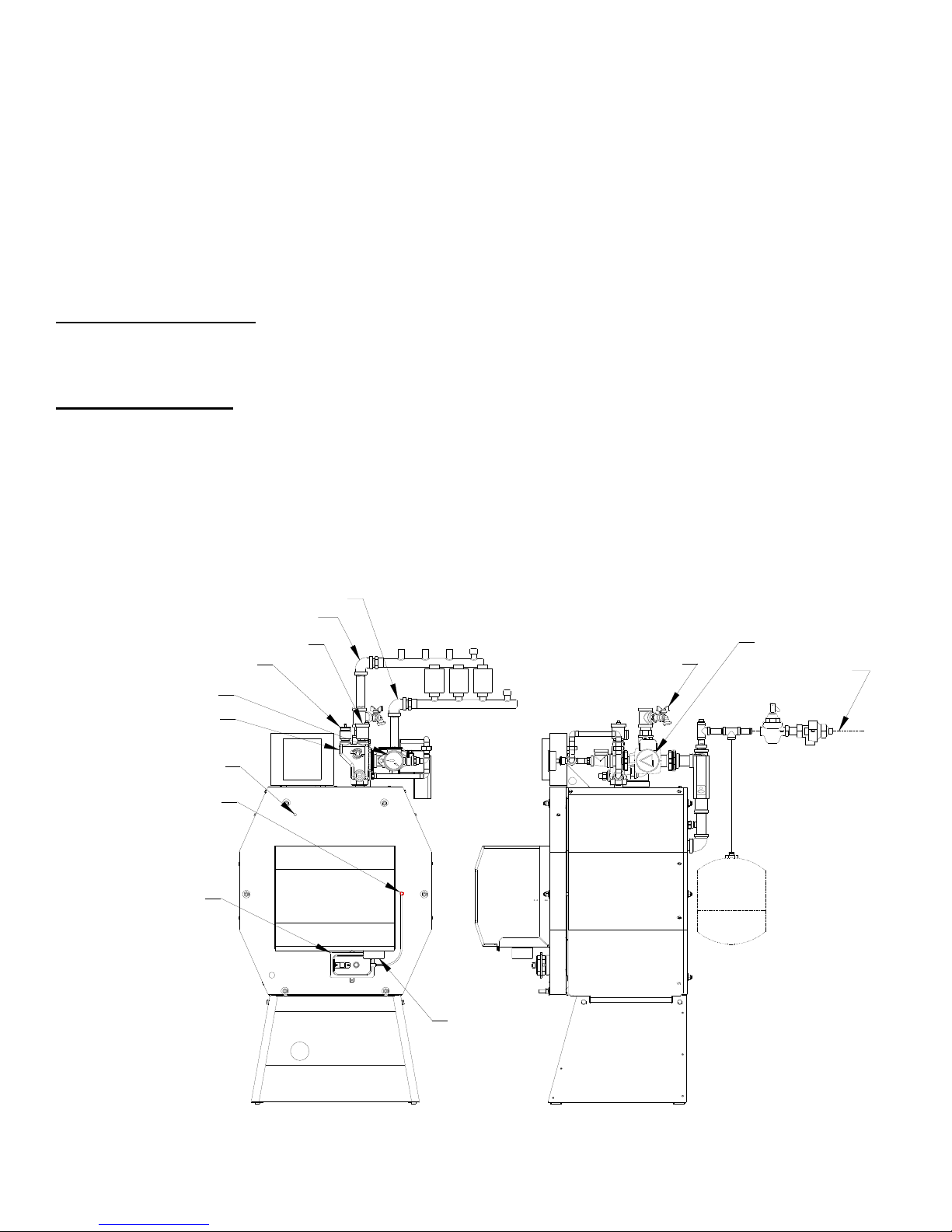
PIPING SO THE DOOR CAN OPEN: To avoid conflicts with the door opening, piping should be in accordance
with FIG. 2A, 2B or dimension D in Fig. 1B. The door opens and drops down to the front of the boiler. The burner and air
box also need clearance when the door opens. Do not locate any piping in front of the boiler unless clearance from the
door is verified. This also applies to the oil line piping and the combustion air piping. NOTICE: Air inlet pipe must be
disconnected to allow door to swing down.
BOILER MOUNTING on BASE, FIG. 2B: The boiler comes on a factory mounted base.
BOILER PITCH: The Resolute pressure vessel is manufactured level with the base. Install the boiler so it is level to
slightly higher at the rear.
T&P Gauge
Return Manifold
Flue Box Test Port
Combustion/Over Fire
Blocked Vent (Puff)
Test Port
Safety Switch
3/4" Air Vent
Relief Valve
Supply
Return
Zone Valves
Return Ball & Purge
System Circ
Feedwater
Connection
Premier Option: Combo
Auto Feed/Backflow
Preventer
Expansion Tank to
be located in return
piping or at the inlet
side of the pump.
Figure 2B
Resolute Oil Heat – PN 10-2025 – July 2018 10
Combustion
Air Inlet
 Loading...