

ENERGYHOME AXHW-20a/250L, AXHW-20a/200L, AXHW-20a/300L Operation And Installation Manual

1
SCHEDE TECNICHE
Il produttore termodinamico è disponibile nelle versioni a pavimento e nei
volumi d’acqua sanitaria per usi domestici di 150 o 200 lt.
La versione 200 LS è dotata internamente di uno scambiatore
solare per l’integrazione da parte di un campo solare termico (max
n 1 pannello a 30° di inclinazione o 2 pannelli a 60° di inclinazione).
- mod. ACS 150 L senza scambiatore
- mod. ACS 200 LS con scambiatore integrato
Il produttore termodinamico può essere installato vicino alla cucina, nel
locale tecnico o in garage. In genere la sua installazione è consentita laddove
sia possibile pensare ad un recupero di calore attarverso l’aria calda negli
ambienti domestici . soprattutto durante il perioddo invernale, aumentando
così l’efcienza globale del sisteam di produzione.
Il prelievo dell’aria calda durante il periodo estivo consente
di aumentare la prestazione del produttore sul lato sanitario
raffrescando così gli ambienti. E’ compatibile acon sorgenti di
calore esterne come caldaie, pompe di calore e fonti rinnovabili.
Ogni produttore è dotato di termostato digitale di regolazione della
temperatura di produzione dell’acqua calda sanitaria (10 - 70°C).
Schema di installazione tipo per il modello ACS 200 LS
Il produttore termodinamico
installato con la fonte rinnovabile
deve prevedere, viste le potenziali
elevate temperature di produzione
estiva, adeguati sistemi di
termostatizzazione sul lato
sanitario.
La termostatizzazione deve
consentire in uscita sul lato utenza
temperature non superiori ai 48°C.
Per ogni produttore termodinamico
è necessario prevedere adeguato
volume di espansione (vaso di tipo
idrico) e valvola di sovrapressione
per impianti idrico-sanitari (tarata
a 6 bar).
Display ACS 150 L/200

PRODUTTORI TERMODINAMICI
Dati tecnici
Modello Codice
150 lt ACS 150 L
Senza fonte rinnovabile Valore
Alimentazione elettrica V/Hz 230/50
Volume acqua lt 150
Potenza massima assorbita W 486
Potenza massima integrazione W 1600
Corrente massima assorbita A 2.2 (+6.8)
Temperatura massima ACS °C 60
Temperatura massima setpoint °C 70
Temperatura ambiente °C -5/+43
Fluido refrigerante - R134A
Pressione massima di scarico bar 20
Pressione minima di scarico bar 6
Refrigerante R134a gr. 120
Capacità termica kW 2.02
COP - 4.16
Portata aria primaria mc/h 460
Connessioni aria IN/OUT mm. DN 180/200
Livello pressione sonora dB(A) 46
Ingombri e peso
Altezza (mm. mm. 1620
Larghezza 585 585
Profondità 585 585
Peso 103 kg 103
Modello Codice
200 lt ACS 200 LS
Senza fonte rinnovabile Valore
Alimentazione elettrica V/Hz 230/50
Volume acqua lt 200
Potenza massima assorbita W 486
Potenza massima integrazione W 1600
Corrente massima assorbita A 2.2 (+6.8)
Temperatura massima ACS °C 60
Temperatura massima setpoint °C 70
Temperatura ambiente °C -5/+43
Fluido refrigerante - R134A
Pressione massima di scarico bar 20
Pressione minima di scarico bar 6
Refrigerante R134a gr. 120
Capacità termica kW 2.02
COP - 4.16
Portata aria primaria mc/h 460
Connessioni aria IN/OUT mm. DN 180/200
Livello pressione sonora dB(A) 46
Ingombri e peso
Altezza (mm. mm. 1780
Larghezza 585 585
Profondità 585 585
Peso 103 kg 103
La resistenza elettrica da 1600 W è inclusa in ambo i modelli.
NB - I dati tecnici sulle potenze si riferiscono alle seguenti condizioni:
- temperatura ambiente 12/20°C
- temperatura dell’acqua da 15 a 55°C.
In cucina
In lavanderia
Con un impianto solare termico
Tipologie di installazione ACS 150 L /200 LS
Sanitary Water Heat Pump
‐
Operation and Installation Manual -
AXHW-20a/200L;AXHW-20a/250L;AXHW-20a/300L

1
TABLE OF CONTENT
INTRODUCTION........................................................................................................................................................2
This manual.........................................................................................................................................................2
The unit................................................................................................................................................................2
SAFETY INSTRUCTIONS........................................................................................................................................3
Warning................................................................................................................................................................3
Caution.................................................................................................................................................................5
ITEMS INSIDE PRODUCT BOX............................................................................................................................. 6
OVERVIEW OF THE UNIT.......................................................................................................................................7
Parts and descriptions.......................................................................................................................................7
Dimensions......................................................................................................................................................... 8
How to replace the magnesium stick..............................................................................................................9
Schematic overview of the water and refrigeration circuit.......................................................................... 9
INSTALLATION.........................................................................................................................................................10
Transportation...................................................................................................................................................10
Required service space...................................................................................................................................11
Installation overview........................................................................................................................................ 12
Installation positions........................................................................................................................................ 14
Water loop connection.....................................................................................................................................15
Water affusion and water emptying.............................................................................................................. 15
Wire connection................................................................................................................................................16
Trial running...................................................................................................................................................... 16
OPERATION THE UNIT......................................................................................................................................... 17
User interface and operation..........................................................................................................................17
LCD icons..........................................................................................................................................................20
PARAMETER CHECKING AND ADUSTMENT..................................................................................................22
Parameter list....................................................................................................................................................22
Malfunctioning of the unit and error codes.................................................................................................. 23
MAINTENANCE....................................................................................................................................................... 25
TROUBLESHOOTING............................................................................................................................................26
ENVIRONMENTAL INFORMATION..................................................................................................................... 26
DISPOSAL REQUIREMENTS...............................................................................................................................26
WIRING DIAGRAM..................................................................................................................................................27
TECHNICAL SPECIFICATION.............................................................................................................................. 28
AXHW-20a/***...................................................................................................................................................28
TEMPERATURE SENSOR R-T CONVERSION TABLE...................................................................................30
READ THIS MANUAL CAREFULLY BEFORE STARTING UP THE UNIT. DO NOT THROW IT
AWAY.KEEP IT IN YOUR FILES FOR FUTURE REFERENCE.
BEFORE OPERATING THE UNIT, MAKE SURE THE INSTALLATION HAS BEEN CARRIED
OUT CORRECTLY BY A PROFESSIONAL DEALER. IF YOU FEEL UNSURE ABOUT
OPERATION, CONTACT YOUR DEALER FOR ADVICE AND INFORMATION.

2
INTRODUCTION
This manual
This manual includes the necessary information about the unit. Please read this manual carefully
before you use and maintain the unit.
The unit
The hot water heat pump is one of the most economical systems to heat the water for family domestic
use. Using free renewable energy from the air, the unit is highly efficient with low running costs. Its
efficiency can be up to 3 ~ 4 times more than conventional gas boilers or electrical heaters.
Waste Heat recovery
Units can be installed near the kitchen, in the boiler-room or the garage, basically in every room which
has a large number of waste-heat so that the unit has the higher energy efficiency even with very low
outside temperatures during the winter.
Hot water and dehumidification
Units can be placed in the laundry room or clothing room. When it produces hot water it lowers the
temperature and dehumidifies the room as well. The advantages can be experienced particularly in the
humid season.
Storage room cooling
Units can be placed in the storage room as the low temperature keeps the food fresh.
Hot water and fresh air ventilation
Units can be placed in the garage, gym, basement etc. When it produces hot water, it cools the room and
supplies fresh air.
Compatible with different energy sources
Units can be compatible with solar panels, external heat pumps, boilers or other different energy
sources.
Ecological and Economical Heating
Units are the most efficient and economical alternative to both fossil fuel boilers and heating systems. By
making use of the renewable source in the air, it consumes much less energy.
Compact design
Units are especially designed for offering sanitary hot water for family use. Its extremely compact
structure and elegant design are suitable for indoor installation.

3
Multiple Functions
The special design of the air inlet and outlet makes the unit suitable for various ways of connections.
With different ways of installation, the unit can work as just a heat pump but also as a fresh air blower, a
dehumidifier, or an energy recovery device.
Other features
Stainless steel tank and a magnesium stick assure the durability of components and the tank.
Highly efficient compressor with the R134a refrigerant.
Electrical element available in the unit as a back-up, assuring constant hot water even in extreme cold
winters.
‐
SAFETY INSTRUCTIONS
To prevent injury to the user, other people, or property damage, the following instructions must be
followed. Incorrect operation due to ignoring of instructions may c ause harm or damage.
Install the unit only when it complies with local regulations, by-laws and standards. Check the main
voltage and frequency. This unit is only suitable for earthed sockets, connection voltage 220 – 240
V~/50Hz.
The following safety precautions should always be taken into account:
- Be sure to read the following WARNING before installing the unit.
- Be sure to observe the cautions specified here as they include important items related to safety.
- After reading these instructions, be sure to keep it in a handy place for future reference.
Warning
Do not install the unit yourself.
Incorrect installation could cause injury due to fire, electric shock, the unit falling or leakage of water.
Consult the dealer from whom you purchased the unit or a specialized installer.
Install the unit securely in a place.
When insufficiently installed, the unit could fall causing injury. The bearing surface should be flat to
bear the weight of the unit and suitable for installing the unit without increasing noise or vibration.
When installing the unit in a small room, please take measures (like sufficient ventilation) to prevent
the asphyxia caused by the leakage of refrigerant.
Use the specified electrical wires and attach the wires firmly to the terminal board
(connection in such a way that the stress of the wires is not applied to the sections).
Incorrect connection and fixing could cause a fire.

4
Be sure to use the provided or specified parts for the installation work.
The use of defective parts could cause an injury due to possible fire, electric shocks, the unit falling
etc.
Perform the installation securely and please refer to the installation instructions.
Incorrect installation could cause an injury due to possible fire, electric shocks, the unit falling,
leakage of water etc.
Perform electrical work according to the installation manual and be sure to use a dedicated
section, fused with 16A.
If the capacity of the power circuit is insufficient or there is an incomplete electrical circuit, it could
result in a fire or an electric shock.
The unit must always have an earthed connection.
If the power supply is not earthed, you may not connect the unit.
Never use an extension cable to connect the unit to the electric power supply.
If there is no suitable, earthed wall socket available, have one installed by a recognized electrician.
Do not move/repair the unit yourself.
If the supply cord is damaged, it must be replaced by the manufacturer or its service agent or a
similarly qualified person in order to avoid a hazard. Improper movement or repair on the unit could
lead to water leakage, electrical shock, injury or fire.
The unit is no intended for use by children.
This appliance is not intended for use by persons (including children) with reduced physical,
sensory or mental capabilities, or lack of experience and knowledge, unless they have been given
supervision or instruction concerning use of the appliance by a person responsible for their safety.
Children should be supervised to ensure that they do not play with the appliance.
Do not tear off the labels on the unit.
The labels are for the purpose of warning or reminding, keeping them can ensure your safe
operations.

5
Caution
Do not install the unit in a place where there is a chance of flammable gas leaks.
If there is a gas leak and gas accumulates in the area surrounding the unit, it could cause an
explosion.
Perform the drainage/piping work according to the installation instruction.
If there is a defect in the drainage/piping work, water could leak from the unit and household goods
could get wet and be damaged.
Do not clean the unit when the power is ‘ON’.
Always shut ‘OFF ’ the power when cleaning or servicing the unit. If not, it could cause an injury due
to the high speed running fan or an electrical shock.
Do not continue to run the unit when there is something wrong or there is a strange smell.
The power supply needs to be shut ‘OFF’ to stop the unit; otherwise this may cause an electrical
shock or fire.
Do not put your fingers or others into the fan, or evaporator.
The inside parts of the heat pump may run at high speed or high temperature, they could cause
serious injury. Do not remove the grills on the fan outlet and top cover.
The hot water probable need to mix with cold water for terminal usage, too hot water (over 50℃)in
the heating unit may cause injury.
The installation height of power supply should be over 1.8m, if any water may spatter, the unit can
be safe from water.

6
ITEMS INSIDE PRODUCT BOX
Before starting the i nstallation, please make sure that all parts are found inside the box.
The Unit Box
Item Image Quantity
Domestic hot water
heat pump
1
Operation and
Installation Manual
1
7
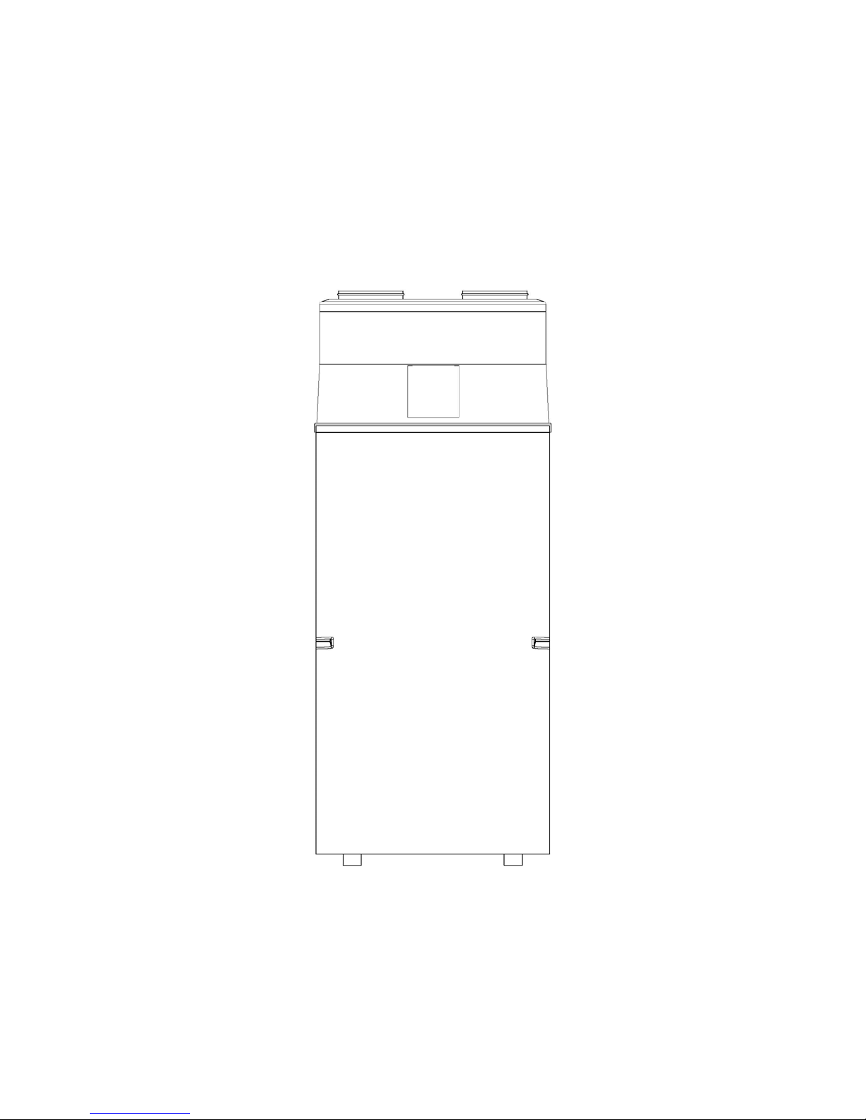
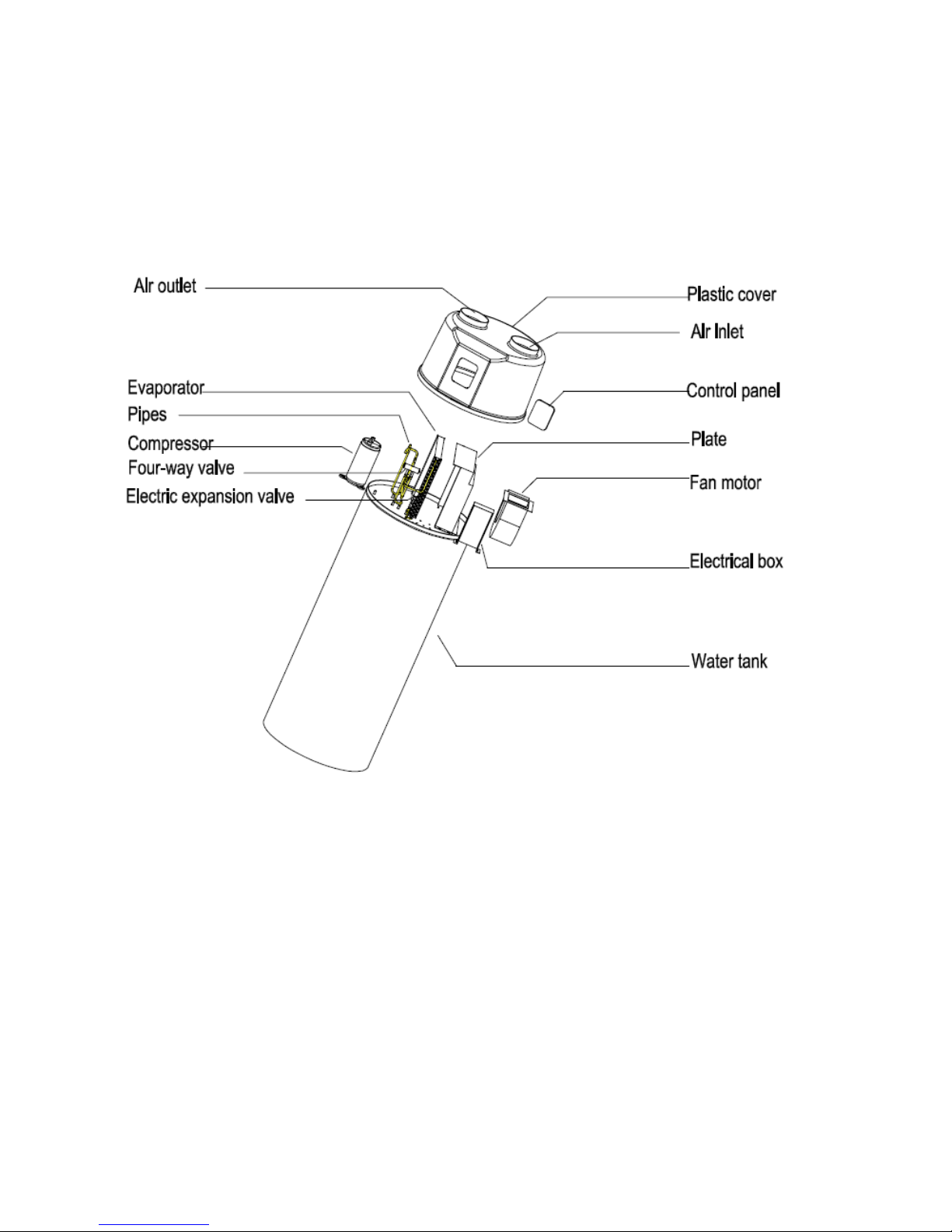
OVERVIEW OF THE UNIT
Parts and descriptions
 Loading...