

Energy Genius GGAT-1 User Manual

User Manual
Energy Genius by PowerSave
Genius Gateway
(GGAT-1)
www.powersave.us
1. General introduction of GG AT-1 Wireless Gateway.
The Energy Genius Gateway receives real time energy usage and temperature information from up to 10 Genius sensors
via wireless signals. The Gateway connects to a router using an Ethernet cable and automatically links the sensors to the
Enerati cloud based management system. Users can use Enerati to monitor and manage their sensors in real time.
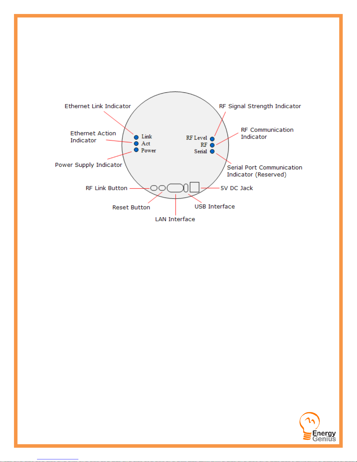
1.1 Interfaces, Buttons and LED indicators
LED Indicator descriptions:
• Link This indicator lights up when Ethernet network link is established.
• Act This indicator flashes when there is data flow in the Ethernet network.
• Power This indicator lights up when the gateway is powered on.
• RF Level This indicator lights up when the RF signal is strong, flashes when signal is weak and lights off when
there is no signal. If there are two or more than two transmitters paired with the gateway, this
indicator will represent the weakest signal’s strength.
• RF This indicator flashes when RF wireless communication is in process.
• Serial This indicator flashes when there is data flow in the serial port (reserved).
Interface and Buttons descriptions:
• DC 5V The DC Jack for power supply.
• USB The USB port for power supply (Also reserved for serial devices).
• LAN The Ethernet network interface. 10/100 Base-T RJ45 interface to connect with network router.
• Reset Press this button to recover the factory default setting. To reset or to clear all paring, history data and web
server setting, press the Reset Button and hold it here for 5 seconds until the right 3 LED indicators all light
up, then release the Reset Button, after 2 seconds, the right 3 LED indicators all light off and all information
has been cleared. Be cautious to use this button since all data will be lost.
• RF Link This button is used to pair the sensor terminals with the gateway.
Genius Gateway User Manual – PowerSave Inc. ©2013 Page 2 of
12
2. Installation and Operation of the Genius gate way.
2.1 Installation Preparation
Power Supply: 100-240VAC, 50/60 Hz
Working Temperature: -10-50℃
Working Humidity: 10-90%, with no
2.2 Installation and Pairing
2.2.1 Power on the gateway and connect it with home Ethernet network.
1) Use the power adapter to connect the gateway’s DC jack with the main power supply until the power indicator
lights up. Or use a USB power adapter to provide power via the gateway’s USB interface until the Power LED
indicator lights up.
2) Plug Ethernet network cable into the LAN interface of the gateway and connect it with a local working router or
home wall network socket, wait until the Link LED indicator lights up, which means the Ethernet network link has
been established.
3) The sensor terminals that can be paired with the gateway include the 1-way power transmitter with sensor clamp,
temperature transmitter, Genius Smart Plug .
condensation.
2.2.2 To pair a Genius CT Sensor with the gateway:
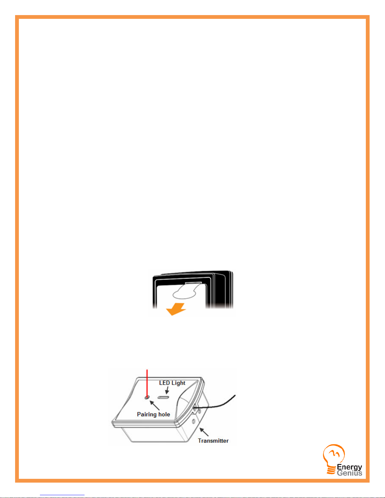
1) Keep the power transmitter as close to the gateway as possible. Pull out the clear plastic tab (marked with
“REMOVE BEFORE USING”) from the back of the transmitter. The tab is an insulation sheet, once it is pulled out,
the built-in batteries will make the transmitter start to work immediately.
2) Press the RF link button of the gateway and hold it there for about 5 seconds until the RF indicator lights up, then
the gateway enters the pairing mode and begins to search for pairing signal.
3) Now use a slim stick to push into the pairing hole of the transmitter (as shown in below photo) and hold it there
for about 3 seconds until the LED light of the transmitter flashes quickly. Then release the slim stick and the
transmitter is now starting to pair with the gateway.
Genius Gateway User Manual – PowerSave Inc. ©2013 Page 3 of
12

4) The pairing may take up to 60 seconds. When the pairing is successfully finished, the RF indicator of the gateway
will flash and the gateway automatically exits the pairing mode. The user will see the transmitter information on
the web page. If the gateway can’t receive a pairing signal from a transmitter in 60 seconds, it will also exit the
pairing mode automatically. While the transmitter will exit the pairing mode after sending pairing signal for
30seconds.
5) Each transmitter has its own MAC ID and after successful pairing, the gateway will regard it as authorized device
and handle its wireless data in the gateway to the distant server.
6) The user may choose to use the embedded web server on the gateway or the Enerati server to add or delete
transmitters.
7) Up to 10 sensor terminals totally can be paired with the gateway.
2.2.3 To pair a Genius Smart Plug with the gateway:
The remote control function is realized via the Smart Plug, which connect the electrical appliances into the system by
working between the appliances and the power supply.
The Genius Smart plug sockets work as the sensor terminals
and detect the power consumption data from the appliances. It also receives and implements the switching on/off
instruction remotely from the gateway. To make the sensor plug socket communicate with the gateway, it need to be
paired with the gateway first.
1) Before pairing, keep the sensor socket closest to
the gateway. Try to locate a power supply wall socket
nearest to the gateway. Attach the sensor plug socket
into the power supply socket and switch on the sensor
socket by pressing its switch button.
2) Press the RF link button of the gateway and hold
it there for about 5 seconds until the RF indicator lights
up, then the gateway enters the pairing mode and
begins to search for pairing signal.
3) Now use a slim stick to push into the pairing hole
of the sensor Smart Plug socket and hold there for
about 6 seconds until the LED light on the sensor plug
socket flashes quickly. The sensor socket is now starting
to pair with the gateway. The pairing may take up to 60
seconds. When the pairing is successfully finished, the
LED light on the sensor socket will stop flashing and the RF indicator of the gateway begins to flash. And the user
can see the sensor socket information on the web page. If the gateway can’t receive a pairing signal in 60 seconds,
it will also exit the pairing mode automatically. While the sensor socket will exit the pairing mode after sending
pairing signal for 60seconds.
4) After the pairing is finished, pull out the sensor socket from the power supply socket near the gateway and attach
it again to the power supply socket near the actual electrical appliance to be monitored and controlled, then
attach the plug of the electrical appliance into the sensor plug socket. And the connected electrical appliance can
now be monitored and controlled via the gateway remotely.
5) Each sensor socket has its own MAC ID and after successful pairing, the gateway will regard it as
authorized device and handle its wireless data in the gateway to the distant server.
Genius Gateway User Manual – PowerSave Inc. ©2013 Page 4 of
12
 Loading...