

Energy Asse EDMI Mk 10 User Manual
Tel: 01506 405 405
energyassets.co.uk
Energy Assets
bringing
meters
to life...
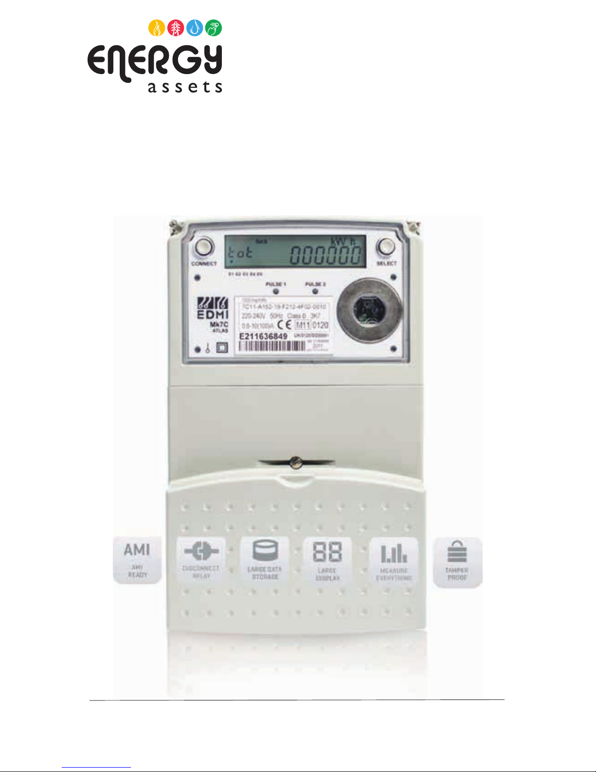
EDMI Mk 10
Electricity Meter
Atlas Series Class 1 and Class 2
The Mk10A is a member of our Atlas series.
Apolyphase meter with CT connected or
Whole Current measurement options, it
includes power quality indication, advanced
commissioning functionality and a large
memory storage
User Guide to LCD
Screen Displays
Tel: 01506 405 405
energyassets.co.uk
Energy Assets
bringing
meters
to life...
EDMI Mk 7C Electricity Meter
1.0 INTRODUCTION
The EDMI Mk10 meter is a new development of ‘Smart’ metering
used to measure Electricity consumption. It is a unique product
which enables energy usage to be continually measured and
stored and then data is transmitted to the Supply Company when
needed for billing. The meter has a large number of features, readily
available, to provide Users with detailed information about their
electricity supply including Tariff (Standard Settlement
Confi guration - SSC), Power Factor, Maximum Demand and Total
Billing Consumption together with individual Rate consumption for
consumers on multi rate tariffs.
In addition, there is an option to obtain analysed billing data
information via a web link. Users can then see a detailed breakdown
of their energy usage and time of use to enable any unplanned
wastage to be eliminated and help manage more effi cient usage, as
part of an energy management process.
2.0 ACCESS TO DISPLAY SCREENS
Access to all the features of the meter
only requires the pushing of a single
‘display’ button on the meter. The
meter has two main displays called
‘Set A’ and ‘Set B’. To move from ‘Set
A’ to ‘Set B’ you simply press and hold
the ‘display’ button for approximately 2
seconds.
Details of all the individual LCD
screens within each ‘Set’ are shown on
the following pages.
To cycle within the ‘Set’ you simply
press the display button and the
display will advance one step.
Continual individual presses of the
button will eventually cycle the display
back to your starting point.
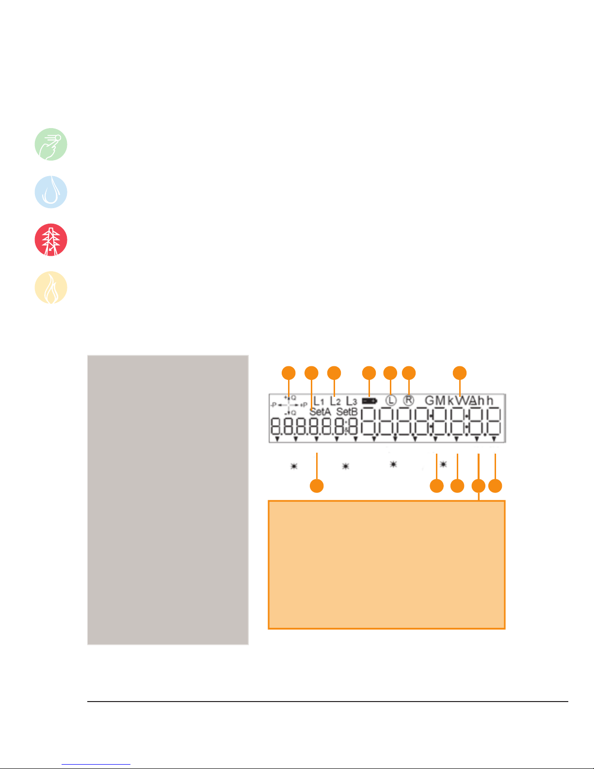
1 INDICATES POWER FLOW
+ P = Import Kw
- P = Export Kw
+ Q = Import kVar (Lag)
- Q = Export kVar (Lead)
2 REGISTERS DISPLAYS
S et A (Main)
S et B (Test)
3 PHASES PRESENT ON METER
4 LOW BATTERY
5 LOCAL COMMS IN USE
( Flag Probe)
6 REMOTE COMMS IN USE
( eg Modem)
7 UNITS BEING MEASURED
8 RATE REGISTERS IN USE
9 INCORRECT PHASE ROTATION
10 M ODEM POWERED
11 ACTIVE ALARMS
( will clear as fault corrected eg Phase Fail)
12 LATCHED ALARMS
( only cleared with fault manufacturer
software)
1 2 3 4 5 6 7
R1 R2 R3 R4 R5 R6 Spare Spare Spare? MP AL1A L2
Wh Pulse Varh Pulse
Spare
8 9
Spare
10
11
12
FLAG LETTERS
E
S
V
F
R
C
M
L
H
X
Y
Z
N
D
U
ALARM NAME
ANALOG REFERENCE FAILURE
ASYMMETRIC POWER
VOLTAGE TOLERANCE ERROR
VT FAILURE
INCORRECT PHASE RESOLUTION
CLOCK FAILURE
REVERSE POWER
CALIBRATION DATA LOST
MODEM FAILURE
RAM FAILURE OR LCD FAILURE
PROGRAM FLASH FAILURE
DATA FLASH FAILURE
PULSING OUTPUT OVERFLOW
BATTERY FAILURE
TAMPER
3.0 THE SCREEN WITH ALL SEGMENTS ILLUMINATED
 Loading...