

Energx Dyna TF6000E, Dyna TF4500E Owner's Manual
OWNERS MANUAL
60707-023
EA8EL)fiw
- - -
-
-
-
-
-
-
-----
--
---
-
--
-
--
---
-
---
-
CORPORATION
READ AND UNDERSTAND ALL INSTRUCTIONS IN
THE MANUAL BEFORE STARTING AND OPERATING
THE GENERATOR SET.
USING THIS MANUAL
Congratulations on your choice of an ENERGX generator set. You have selected
a
high-quality, precisionengineered generator set designed and tested to give
you years of satisfactory portable service.
To get the best performance from your new engine
generator set, it is important that you carefully read and
follow the operating instruction in this manual.
Should you experience a problem please follow the
"Things To Check" near the end of this manual. The
warranty in the back of this manual describes what you
can expect from ENERGX should you need service
assistance in the future.
PROPER USE AND INSTALLATION
You must be sure your new engine generator set is:
*
Properly serviced before starting
Operated in a well ventilated area
*
Exhaust gases are dispersed safely
Wired by a qualified electrician
Operated only for its designed purposes
*
Used only by operators who understand its
operation
Properly maintained
TABLE
OF CONTENTS
PAGE
INTRO
......................................
I
GUIDE TO PRODUCT SAFETY
................
A1
BASIC INFORMATION
.......................
B1
Specifications..
.........................
B1
Intended Uses
...........................
B1
Restricted Uses
.........................
B1
Unit Capabilities.
........................
B1
Where is Everything Located
..............
82
PREPARING THE UNIT
......................
C1
Unpacking the unit
......................
C1
Oil Requirements
........................
C2
Fuel Requirements.
......................
C2
Battery Installation.
......................
C3
BASIC OPERATION
.........................
Dl
Operating Procedure
.....................
Dl
Connecting the Loads..
..................
D3
Conserver operation
.....................
D3
Low Oil Shutdown Operation
..............
D3
INSTALLATION
.............................
El
Wiring
.................................
El
OPERATOR MAINTENANCE
..................
F1
Engine Care
............................
F1
Generator Care
..........................
F1
Unit Cleaning
...........................
F1
Things to Check before you call for Service . F2
.......................
ENERGX WARRANTY
COPY YOUR MODEL AND SERIAL
NUMBER HERE
No other ENERGX generator has the same serial number as yours. It is important that you record the number
and other vital information here, if you should ever need
to contact us on this unit it will help us to respond to
your needs faster.
MODEL
................
SERIAL NUMBER..
......
DATE PURCHASED
......
DEALER.
...............
GUIDE
TO
PRODUCT SAFETY
This engine generator set has been designed and
manufactured to insure your personal safety. Improper
use can result in potential deadly hazards; from electrical shock, exhaust gas asphyxiation, or fire. Please
read all safety instructions carefully before installation
or use. Keep these instructions handy for future reference. Take special note and follow all warnings on the
unit and in the manuals.
CAUTION:
Possible Damage to Equip-
ment. CAUTION notes indicate any con-
[-]
dition or practice, which if not strictly
observed or remedied, could result in
damage or destruction of the equipment.
WARNING:
Personal Danger. WARNING notes indicate any condition or
practice, which
if
not strictly observed,
could result in personal injury or possible loss of life.
a
ELECTRIC SHOCK
-
The output voltage present in this equipment can cause a fatal electric
shock. This equipment must be operated by a
responsible person.
A. Do not allow anyone to operate the genera-
tor without proper instruction.
B. Guard against electric shock.
C. Avoid contact with live terminals or receptacles.
D. Use extreme care
if
operating this unit in rain or
snow.
E.
Use only three-prong grounded receptacles and
extension cords.
F. Be sure the unit is properly grounded to an ex-
ternal ground rod driven into the earth.
2.
FIRE HAZARD
-
Gasoline and other fuels always pre-
sent a hazard of possible explosion
andlor fire.
A. Do not refuel when the engine is running or hot.
Allow the engine to cool at least two minutes
before refueling.
B. Keep fuel containers out of reach of children.
C. Do not smoke or use open flame near the
generator set or fuel tank.
D. Keep a fire extinguisher nearby and know its pro-
per use. Fire extinguishers rated ABC by NFPA
are appropriate.
E. Store fuel only in an approved container, and on-
ly in a well-ventilated area.
3.
DEADLY EXHAUST GAS
-
Exhaust fumes from any
gasoline engine contain carbon monoxide, an odorless and deadly gas that must be mixed with fresh
air.
A. Operate only in well ventilated areas.
B
.
Never operate indoors.
C. Never operate the unit in such a way as to allow
exhaust gases to seep back into closed rooms (i.e.
through windows, walls or floors).
4.
NOISE HAZARD
-
Excessive noiseis not only tiring, but continual exposure can lead to loss of
hearing.
.
A .Use hearing protection equipment when working
around this equipment for long periods of time.
B. Keep your neighbors in mind when permanently
installing this equipment.
5.
CLEANLINESS
-
Keep the generator and surrounding
area clean.
A. Remove all grease,
ice,s.now or materials that
create slippery conditions around the unit.
B.Remove any rags or other material that could
create potential fire hazards.
C.Carefully wipe up any gas or oil spills before start-
ing the unit.
D .Never allow leaves or other flammable material to
build up around the engine exhaust area.
6.
SERVICING EQUIPMENT
-
All service, including the
installation or replacement of service parts, should
be performed only by a qualified technician.
A .Use only factory approved repair parts.
B.Do not work on this equipment when fatigued.
C.Never remove the protective guards, cover or
receptacle panels while the engine is running.
D.Use extreme caution when working on electrical
components. High output voltages from this equip-
ment can cause serious injury or death.
E. When servicing this unit always avoid hot mufflers,
exhaust manifolds, and engine parts. They all can
cause severe burns instantly.
F. Installing and wiring a home-standby generator is
not a "do it yourself" project. Consult a qualified,
licensed electrician or contractor. The installation
must comply with all national, state, and local
codes.
SPEClFlCA TIONS
*Rating based on gasoline. For LP derate 1O0/0 for
natural gas derate 20%.
**Cranking Performance at 80 Degree F. 190 CCA.
MODEL
Generator
Continuous Watts'
Volts
AM Ps
Receptacles
NEMA 5-15 (120V)
N EMA 5-50 (1 20V)
N
EMA 6-30 (240V)
Engine
Size
Model
TY pe
Fuel Capacity
Fuel Consumption
Full Load gas
LP
NG
Starting System
Stop System
Low Oil Shutdown
Muffler
Complete Unit
Weight (dry)
Dimensions
LxWxH
Dolly Wheels
Owner Must
Provide
Fuel
Oil Type
Oil Capacity
Battery Size
INTENDED USES
1.
These engine generator sets have been designed
primarily for portable use. Receptacles are provided
in the control panel on the generator for you to plug
in your loads (portable appliances and tools). These
generators are designed with full power capabilities.
See unit capabilities for further explanation.
2. These units require large quantities of fresh air for
cooling of both the engine and the generator. Fresh
air is drawn from both the engine end and the generator end and is exhausted at the center of the unit.
For safety, long life and adequate performance,
these units should never be run in small compartments without positive fresh air flow.
TF4500E TF6000E
4000 5500
1201240 1201240
33.311 6.7 45.8122.9
4
4
1 1
1 1
8HP 11HP
195437 254427
See Engine Shroud Above
Recoil For Type
----.--em--m-
41/* GAL
------------.
.87glhr 1.09glhr
6.'/#lhr 7.7#lhr
110CuFtlhr 155CuFtlhr
---------
RecoillElect ric---------
--------------
Panel Switch
--------------
-----------------
Standard
-----------------
Super Low Tone with Spark
Arrestor
160 LBS 199 LBS
29x19~24 29x1 9x24
.----------.----.
Optional
-----------------
Unleaded Gas or LP or NG
10W-30 for Service SF, SE,
SD, SC. See engine manual
for additional info
23/4 Pints
3
Pints
Ul*' Ul*'
RESTRICTED USES
1.
DO NOT remove from the cradle assembly. Removal of the generator from the cradle assembly may
cause excessive vibration and damage to the engine
generator set.
2. DO NOT install and operate these portable generators in small compartment.
(i.e. generator compart-
ment of vehicles, motor homes, or travel trailers)
These compartments will not allow enough free flow
fresh air to reach the engine generator set for cool-
-
ing and will allow the unit to overheat damaging both
the engine and the generator. Small compartments
will also develop hot spots where there is very little
air flow and may cause a fire.
3.
DO
NOT attempt to operate this unit at 50 cycles.
These units are designed and are governed to operate at 60 Cycles only. Special units are available for
50 cycle operation.
UNIT CAPABILITIES
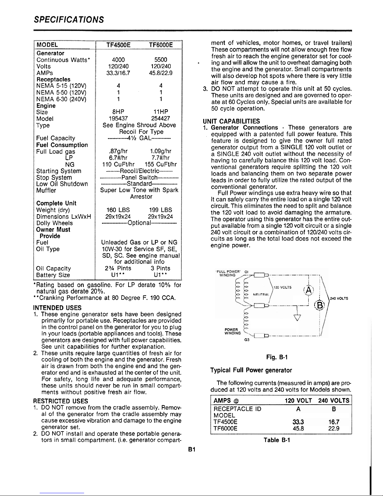
1. Generator Connections - These generators are
equipped with a patented full power feature. This
feature is designed to give the owner full rated
generator output from a SINGLE 120 volt outlet or
a SINGLE 240 volt outlet without the necessity of
having to carefully balance this 120 volt load. Conventional generators require splitting the 120 volt
loads and balancing them on two separate power
leads in order to fully utilize the rated output of the
conventional generator.
Full Power windings use extra heavy wire so that
it can safely carry the entire load on a single 120 volt
circuit. This eliminates the need to split and balance
the 120 volt load to avoid damaging the armature.
The operator using this generator has the entire output available from a single 120 volt circuit or a single
240 volt circuit or a combination of 1201240 volts circuits as long as the total load does not exceed the
engine power.
j
,j.
240
VOLTS
!
B!
)
1-
v
v
POWER
WINDING
G3
Fig. B-1
Typical Full Power generator
The following currents (measured in amps) are pro-
duced at 120 volts and 240 volts for Models shown.
AMPS
@
120 VOLT 240 VOLTS
RECEPTACLE
ID
MODEL
TF4500E
TF6000E 45.8 22.9
Table B-1
B 1

SPECIFICATIONS
(continued)
2.
Starting Electric Motors - Electric motors require
much more current (amps) to start them than to run
them. Some
moJors, particularly low cost split-phase
motors are very-hard to start and require 5 to 7 times
as much current to start them as to run them. Capacitor motors are easier to start and usually require
2 to 4 times as much current to start them as to run
them. Repulsion Induction motors are the easiest to
start and usually require
1% to 2% times as much
to start them as to run them.
Most fractional horsepower motors take about the
same amount of current to run them whether they
are of Repulsion-Induction (RI), Capacitor (Cap), or
Split-Phase (SP) type. The chart below shows the approximate current required to start and run various
types of sizes of 120 volt 60 cycle electric motors
under average load conditions.
RUNNING
Sf
ARTlNG AMPS
HP AMPS SP CAP
R
I
116 3.2
16 TO 22 6 TO 13
5 TO 8
114 4.5
22TO32
9TO18 7TO12
113 5.2
26TO35 10TO21
8TO17
112 7.2
NOT MADE 14 TO 29
11 TO 18
1 13.0
NOT MADE 26 TO 52
20 TO 33
and no harm is done. Under these conditions the
motor may revolve a few times when it is first turned
on, and then stop.
On the other hand, suppose an electric motor that
requires just a little more output than the generator
can produce is connected to it. It will run but will not
reach a high enough speed for the centrifugal switch
to disconnect the starting winding. The generator
output voltage, instead of being 120, may drop to 70
or 80 volts. RUNNING THE GENERATOR UNDER
THESE CONDITIONS MAY RESULT IN BURNING
OUT THE GENERATOR ARMATURE AS WELL AS
THE MOTOR WINDINGS.
Because the heavy surge of current required for
starting motors is required for only an instant, the
generator will not be damaged
if
it can bring the
motor up to speed in a few seconds of time. If difficulty is experienced in starting motors, turn all
other electrical loads off and if possible reduce the
load on the electric motor.
3.
Motor Starting Capacity - listed below you will find
the motor starting capability of your engine generator set.
The figures given above are for average load such
as a blower or fan. If the electric motor is connected
to a hard starting load such as an air compressor,
it will require more starting current. If it is connected
Trying to start a larger motor or a higher code (ie
to a light load, or no load such as a power saw, it
J
or
K)
motor may result in damage to both the gen-
will require less starting current. The exact require-
erator and the electric motor, especially 120 volt
ment will also vary with the brand or design of the motors.
motor.
For 240 volt motor, the "running" current is half
WHERE IS EVERYTHING LOCATED
as much as shown for the 120 volt motors of the
same size. Some dual voltage 1201240 volt motors
are difficult to start on 240 volts when driven by
enginelgenerators and can be started more easily when
connected to operate on 120 volts. This is particularly
true of "capacitor start-induction run" motors.
Sometimes a 240 volt motor which cannot be started
on the 240 volt circuit of a 1201240 volt generator can
be started on a 120 volt circuit and then quickly
switched to the 240 volt circuit after it is started. This
can be done in applications where the motor is manually controlled and is started under "no load" conditions.
A self-excited generator responds differently to
severe overloading than a transformer connected to
a power line. To illustrate, suppose that a 240 volt
5
H.P.
"capacitor start-Induction Run" motor is connected to a small transformer that would not be able
to supply enough power to bring the motor up to operating speed. It would be very severely overloaded
and probably would burn out in a short time. The
motor might also be damaged. When this motor is
connected to a self-excited 4000 watt generator, its
output voltage drops to practically zero. Thus, there
is virtually no load on the generator or the engine,
1. Starter
2. Battery Positive Connection
3. Battery Negative Connection
4. Fuel Mixture Valve
5.
Vapor Fuel Connection Point
6. Demand Regulator
7. Start Switch
 Loading...