

Page 1

P/N 1706-3421
REV 03 Printed 0900-2000
Specifications Subject to Change
1001 Oakdale Road, Oakdale, PA 15071-1500
(412) 788-4353 • Toll Free 1-800-DETECTS
FAX 412-788-8353 • Service Dept. 1-888-788-4353
Multi-Gas Monitor
ATX612
Instruction
Manual
GUARANTEED.
FOR LIFE.
INDUSTRIAL SCIENTIFIC
CORPORATION
Page 2

OUR MISSION
Design - Manufacture - Sell:
Highest quality products
for the preservation of
life and property.
Provide:
Best customer service
available.
Page 3

Dear Valued Customer,
Thank you for buying and using Industrial Scientific’s
Model ATX612 Multi-Gas Monitor.
Your ATX612 can be relied upon for dependable service,
day after day. It has been designed, manufactured, tested
and proven under the most scrutinizing conditions
possible. With the minimal care and maintenance
described in this Instruction Manual, it will provide you
with years of reliable monitoring.
I am most concerned that you be pleased with the
performance of your ATX612 in the months and years
ahead. I urge you to call us with any questions or
comments you may have. Often times a phone call and a
question can save you hours of frustration. Please never
hesitate to contact me at 1-800-DETECTS (338-3287).
All of us at Industrial Scientific appreciate the opportunity
to serve you.
Sincerely,
Kent D. McElhattan
President & CEO
Industrial Scientific Corporation
1
Page 4

Multi-Gas
Monitor
ATX 612
1. W
ARNINGS ANDCAUTIONARYSTATEMENTS
3
2. U
NPACKINGTHEINSTRUMENT
4
3. ATX612 F
EATURES
4
4. I
NSTRUMENTOPERATION
5
4
.1 Charging the Battery
5
4.1.1 Alkaline Battery Option 8
4.2Turning the ATX612 On and Off 8
4.3 Display Backlight 8
4.4 Internal Sampling Pump 8
4.5 Operating Modes 9
4.5.1 Reading 9
4.5.2 Sensor Configuration 9
4.5.3 PPM Hydrocarbon 9
4.5.4 Zero 9
4.5.5 Peak 9
4.5.6 Peak Clear 10
4.5.7 Date 10
4.5.8 Cal Date 10
4.5.9 Log Time 10
4.5.10 TWA 10
4.5.11 STEL 10
4.5.12 Hygiene Reset 10
4.6 Alarm Indicators 10
4.6.1 Low Alarm 10
4.6.2 High Alarm 11
4.6.3 Over-Range Indication 11
4.6.4 Combustible Gas Over-Range 11
4.6.5 Low Battery Warning 11
4.6.6 Battery Failure 12
4.6.7 Fault Indication 12
5. C
ALIBRATING THE
ATX612 12
6. C
HANGINGINSTRUMENTSETTINGS
15
6
.1 Setspan
15
6.2
Alarms
16
6.3 Code 17
7. H
YGIENE/DATALOGGINGFUNCTIONS
17
7.
1 Definition of Terms 17
7.1.1 Data Log 17
7.1.2 Period 18
7.1.3 Logging Session 18
7.1.4 Real Time Clock 18
7.1.5 Log Time Clock 18
7.1.6 Calendar 18
7.1.7 TWA 18
7.1.8 STEL 18
7.2 Principles of Operation 18
7.3 Resetting the Hygiene Functions 19
7.4 Downloading the ATX612 19
8. MAINTENANCE 20
8.1 Cleaning 20
8.2 Changing the Battery 20
8.2.1 Replacing the Nicad Battery Module 20
8.2.2 Replacing Alkaline Battery Cells 21
8.3 Opening the Instrument for Service 21
8.4 Installing or Changing Sensors 21
8.4.1 Toxic/Oxygen Sensor Removal/Replacement 22
8.4.2 Combustible Sensor Removal/Replacement 22
8.5 Changing the Internal Filter 22
9. R
EPLACEMENTPARTS
23
10. S
PECIFICATIONS
26
11. D
EFAULTALARMSETTINGS
27
12. ATX612 O
PTIONS
& O
RDERINGINFORMATION
27
13. W
ARRANTY
28
TABLE OF CONTENTS
2 3
1.
W
ARNINGS ANDCAUTIONARYSTATEMENTS
Failure to perform certain procedures or note certain
conditions may impair the performance of the
instrument. For maximum safety and performance,
please read and follow the procedures and conditions
outlined below.
Oxygen deficient atmospheres may cause combustible
gas readings to be lower than actual concentrations.
Oxygen enriched atmospheres may cause combustible
gas readings to be higher than actual concentrations.
Calibrate the combustible gas sensor after each
incident where the combustible gas content causes the
instrument to latch in the OVER-RANGE alarm condition.
Silicone compound vapors may affect the combustible
gas sensor and cause readings of combustible gas to be
lower than actual gas concentrations. If the instrument has
been used in an area where silicone vapors were present,
always calibrate the instrument before next use to ensure
accurate measurements.
Sensor openings and water barriers must be kept clean.
Obstruction of the sensor openings and/or contamination
of the water barriers may cause readings to be lower than
actual gas concentrations.
Sudden changes in atmospheric pressure may cause
temporary fluctuations in the oxygen reading.
Recharge battery only in a non-hazardous location.
Use the RS-232 port only in a non-hazardous location.
Instrument is tested for intrinsic safety in explosive
gas/air (21% oxygen) mixtures only.
CAUTION: High Over-Range (+OR) combustible
gas readings may indicate an
explosive concentration of
combustible gas.
!
!!!!!!!!!
Page 5

4 5
2.
U
NPACKING THEINSTRUMENT
The shipping box should contain the following items.
Account for each item before discarding the box.
QUANTITY PART NUMBER DESCRIPTION
1 1810-2707 ATX612 Multi-Gas Monitor
1 1706-3421 ATX612 Instruction Manual
1 1706-3256 Maintenance Tool
1 1810-0628 Shoulder Strap
1 1810-3077 Charging Adapter
(with Nicad Battery Only)
1 1705-1710 Power Cord
After unpacking, if any listed item is missing, contact
either your local distributor of Industrial Scientific products,
or call Industrial Scientific Corporation at 1-800-DETECTS
(338-3287) in the United States and Canada, or
412-788-4353.
3.
ATX612 F
EATURES
The Industrial Scientific ATX612 Multi-Gas Monitor may
be configured to continuously monitor one, two, three or
four gases in any combination of the following:
• Oxygen
• Combustible gases (%LEL) or methane (% by volume
CH
4
). User selects %LEL or %CH4prior to calibration.
• Any two of the following toxic gases:
Carbon Monoxide
Hydrogen Sulfide
Sulfur Dioxide
Chlorine
Nitrogen Dioxide
Chlorine Dioxide
• The ATX612 automatically recognizes and displays the
installed sensors when switched on.
• One-Button calibration (microprocessor controlled).
• Built-in pump for remote gas sampling.
• Backlit display for viewing in low light conditions.
• Round-the-clock monitoring capability using the
interchangeable rechargeable nickel-cadmium (Nicad) or
replaceable alkaline battery packs.
• Plug-in sensors that can be changed or replaced without
special tools or soldering equipment.
• 90 dB audible and ultra-bright visual alarm indicators.
• Optional external audible or vibrating alarms.
• High and low alarms for combustible and toxic gases;
enrichment and depletion alarms for oxygen.
• User selectable latching alarms.
• User selectable access code for security of calibration
and alarm settings.
• Combustible gas OVER-RANGE protection.
• PEAK reading mode.
• Press and hold power switch to prevent accidental turn
ON or turn OFF.
• Hygiene/Datalogging option that can be installed by the
factory or the customer, to provide short term exposure
limit (STEL) and time-weighted average (TWA)
readings with 110 hours datalogging capacity.
• The ATX612 is classified as intrinsically safe by the
following agencies:
- Underwriters Laboratories (UL).
- Canadian Standards Association (CSA). Canadian
Standards Association has assessed only the
combustible gas portion of this instrument for
performance.
- Mine Safety and Health Administration (MSHA).
- Workcover Authority, NSW , Australia.
- Department of Mineral Resource, NSW, Australia.
- CENELEC (DEMKO)
4.
I
NSTRUMENTOPERATION
4.1 CHARGING THE BATTERY
(NICAD BATTERY OPTION)
If the ATX612 is equipped with a Nicad battery pack, fully
charge the battery pack before use. A universal charging adapter
is included with the unit for charging the ATX612 battery pack.
The battery pack may be charged while attached to the
instrument or when removed to allow round-the-clock operation
of the ATX612 using a spare battery.
The ATX612 is equipped with a nickel-cadmium battery pack
with a built-in “smart” charging system. When plugged into the
charging adapter, the battery will recharge at a high rate until
fully charged and then will reduce to a maintenance trickle
charge rate. The battery will not be damaged if it is left
connected to the charger for extended periods.
Page 6
INDUSTRIAL
SCIENTIFIC
ATX612
OXYGEN
LEL
E
BATT
PPM
%
ON/OFF MODE
6 7
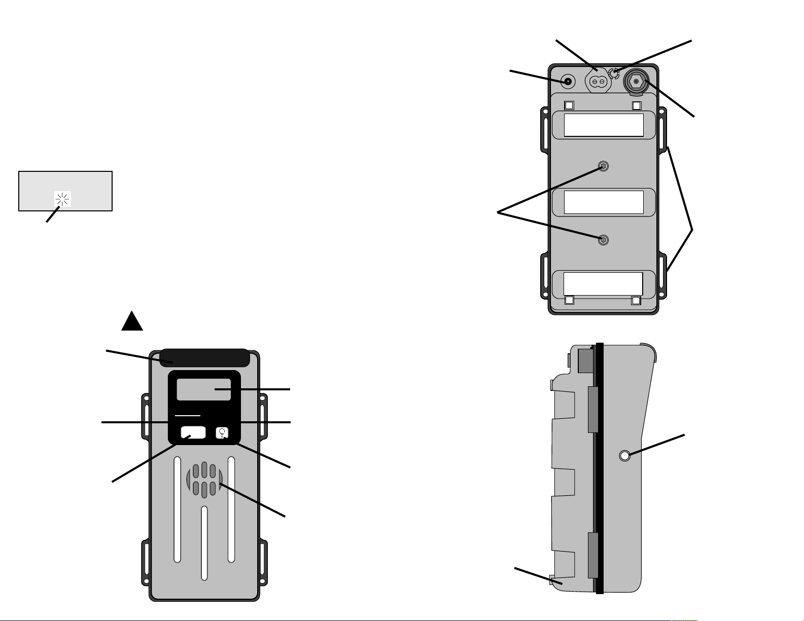
Hidden (+) Key
Alarm Speaker
On/Off/Mode Key
Ultra-bright Visual
Alarm Light Bar
Battery Status
Indicator
Hidden (-) Key
Display
Enter/Backlight Key
Charging Socket
(Nicad Versions)
Infrared Data Interface
Gas Sample Inlet
Fitting
Pump Exhaust Port
Shoulder Strap/
Optional Handle
Attachment
Battery Pack
Hex Screws
External Alarm Jack
Interchangeable Nicad
or Alkaline Battery
Pack
A dead battery will be fully recharged in 4.5 hours. The
Nicad battery pack has a LED charge status indicator to
show the current status when connected to the charger.
The LED indicator has five states as follows:
• Solid Amber: Fast charge in progress
• Solid Green: Fully charged, in trickle
charge mode
• Flashing Green: Battery too hot/cold to be
fast charged, in trickle
charge mode
• Flashing Amber: Instrument running, fast
charge mode
• Alternating Green/Amber: Trouble, electrical problem
in battery pack
A fully charged Nicad battery pack will typically operate a
four-gas configured ATX612 for up to 16 hours. When the
instrument is in the normal viewing mode, an eightsegment battery status indicator continuously displays the
battery condition. Each segment represents approximately
2 hours of operating time. When the battery is fully
discharged, the display will read BATTERY FAIL and the
instrument will emit a short beep once a second (See
Section 4.6.6). Turn off the instrument and recharge the
battery pack when BATTERY FAIL appears.
WARNING: Recharge Nicad battery pack only in a
non-hazardous location.
00
21.0 0
Figure 1
Figure 2
Figure 3
!
Page 7

8 9
CO H2S
02 LEL
ATX612
VER 1.0
5
O 0
21.0 0
The remote sample tube should be connected to the barbed
inlet fitting on the bottom of the ATX612 (See Figure 3).
NOTE: When drawing a remote sample, allow 2 seconds
per foot (0.3 meter) of tubing length in addition to
the normal sensor response time before observing
the instrument readings.
The instrument is protected from drawing liquid and dust
into the pump and sensors by an internal 1.2 micron dust
filter/water stop.
4.5 OPERATING MODES
The ATX612 offers different operating modes to access
various instrument features. To scroll through the
operating modes, press and release the MODE switch. The
operating modes will appear in the following order:
4.5.1 READING
This is the normal operating mode. The current reading of
all sensors is displayed along with the graphical battery
charge indicator.
4.5.2 SENSOR CONFIGURATION
This mode will display the type of sensor in the position in
which it is installed in the instrument.
4.5.3 PPM HYDROCARBON
This mode displays the level of total hydrocarbons with 50
PPM resolution. The PPM reading may be rezeroed at
anytime by pressing the enter (E) key. The display will
return to the normal operating mode if the gas
concentration exceeds the LEL alarm level set in the
instrument.
4.5.4 ZERO
This mode allows the user to zero the instrument and
calibrate all installed sensors. Refer to Section 5,
Calibrating the ATX612, for instruction on the use of the
automatic zero and calibration functions.
4.5.5 PEAK
This mode will display the highest level of toxic and
combustible gas and the lowest level of oxygen measured
since the peak readings were last cleared.
HOLD
RELEASE
4.1.1 ALKALINE BATTERY OPTION
The ATX612 is available with an optional alkaline battery
pack which will typically operate continuously for up to
20 hours using 6 C-cell batteries.
WARNING:
Replace alkaline battery cells only in a
non-hazardous location. Use only Duracell, Energizer,
Procell, Panasonic, Varta or Kodak C-cell alkaline batteries. Use
of another battery type may present a risk of fire or explosion
and will violate the intrinsic safety certification of the ATX612.
4.2 TURNING THE ATX612 ON AND OFF
• Press and hold the ON/OFF/MODE switch. The display
will read HOLD and the instrument sounds a short beep
once a second.
• Continue holding the MODE switch for 5 beeps until the
RELEASE screen appears. (Stop here if turning the
instrument off.)
• After the instrument is turned ON, the following startup
screens will be displayed:
SOFTWARE VERSION: The version of the operating
software installed in the instrument is displayed.
SENSOR CONFIGURATION. The type of sensors
installed in the instrument will be displayed.
WARM-UPTIMER. The display will indicate the
number of seconds remaining until the instrument begins
normal operation.
After the warm-up sequence has been completed, the
ATX612 will enter the normal operating mode and will
be continuously monitoring all calibrated sensors.
4.3 DISPLAY BACKLIGHT
The display backlight is automatically switched on when
the ATX612 is in an alarm condition. To manually activate
the backlight, press and release the (E) key. The backlight
will remain on for approximately 15 seconds.
4.4 INTERNAL SAMPLING PUMP
The ATX612 is equipped with a built-in pump for remote
gas sampling. The sampling pump will draw a constant flow
sample from up to 100 feet (30 meters) using 1/8 inch (3
mm) diameter tubing.
CO H2S
02 LEL
PPM EXP
0
ZERO
PRESS
65P 8
19.3K 12
!
Page 8

10
11
4.6.2 HIGH ALARM
When a monitored gas concentration reaches the high
alarm level setpoint, the instrument emits a continuous dual
tone alarm. As with the low alarm condition, the red alarm
light bar and backlight will flash simultaneously with the
displayed gas value. If the hygiene/datalogging option is
installed, the STEL alarm will mimic the high alarm
indicator and the STEL display value in alarm will flash.
NOTE: The ATX612 uses the continuous high alarm tone
for both low (depletion) and high (enrichment)
oxygen alarm conditions.
4.6.3 OVER-RANGE INDICATION
An over-range condition occurs when a sensor reading
exceeds the upper limit of the instrument display range.
Over-Range is indicated by +OR in the appropriate sensor
display location. With the exception of combustible gas
over-range, all over-range conditions will clear
automatically when the gas concentrations have decreased
to levels within the display range of the instrument.
4.6.4 COMBUSTIBLE GAS OVER-RANGE
When the ATX612 detects combustible gases in excess of
100% of LEL (5% CH4 by volume), a high alarm
condition is latched (locked on) and +OR is displayed in
place of the combustible gas reading. Power is removed
from the combustible gas sensor to prevent damage due to
the high level of combustible gas.
To clear the combustible gas over-range alarm:
• Exit the hazardous area immediately.
• Press (E) key in clean air.
NOTE: When the instrument is turned on, the combustible
gas level must be less than 100% of LEL (5%
CH
4
) to clear the combustible gas over-range
condition.
4.6.5 LOW BATTERYWARNING
With 15-60 minutes of run time remaining, the ATX612
will emit a short beep once every 60 seconds and the
battery status indicator will be replaced with a flashing
“B” to indicate the low battery condition.
NOTE: The length of warning time will increase when
there is no combustible gas sensor installed in the
instrument.
4.5.6 PEAK CLEAR
This mode will clear all stored peak readings from the
instrument. Press enter (E) to clear the peak readings. The
display will return to the PEAK mode and indicate that the
peak readings have been reset.
If the hygiene/datalogging option is installed, the following
operating modes may also be accessed. See Section 7,
Hygiene/Datalogging Functions, for further instructions.
4.5.7 DATE
This screen allows the user to see the current date
(month/day).
4.5.8 CALDATE
This mode allows the user to see the date the instrument
was last calibrated.
4.5.9 LOG TIME
This mode allows the user to view the current real time
(RT) and the length of time that data has been recorded in
the current session (LT).
4.5.10 TWA (Time-Weighted Average)*
This mode displays the current time-weighted average
exposure values of the toxic sensors.
4.5.11 STEL (Short Term Exposure Limit)*
This mode displays the short term average exposure values
of the toxic sensors installed in the instrument.
4.5.12 HYGIENE RESET
This mode allows the user to reset the hygiene session and
the STEL and TWA exposure values.
4.6 ALARM INDICATORS
4.6.1 LOW ALARM
When a monitored gas concentration reaches the low level
alarm setpoint, the instrument emits a short beep
approximately every 1.2 seconds. The red alarm light bar
and backlight will flash simultaneously along with the
displayed gas value. If the hygiene/datalogging option is
installed, the TWA alarm will mimic the low alarm
indicator and the TWA display value in alarm will flash.
CALDATE
5/13
RT06:45
LT01:15
0 0
TWA
0 0
STEL
+OR 0
21.0 0
HYGIENE
PRESS
DATE
5/21
O 0
21.0 +OR
O0
21.0 0
B
*
TWA and STEL
readings do not
apply to oxygen
and combustible
gas exposure.
PK CLR
PRESS
Page 9

12
13
ZERO
PRESS
ZEROING
21.0
02 CAL
4.6.6 BATTERY FAILURE
When the battery has insufficient charge to operate the
instrument, “BATTERY FAIL” is displayed. The visual
alarm will be activated and the instrument will emit a
short beep once every second for approximately 30
seconds after which the instrument will turn itself off.
Recharge or replace the battery (See Section 8.2).
4.6.7 FAULT INDICATION
The ATX612 will emit a short beep once a second if a
newly installed sensor does not agree with the previous
sensor type for that position. The corresponding display
position will be blank. This fault indication also occurs
when a sensor becomes disconnected or a combustible
sensor fault is detected during normal operation. Installed
sensor types are accepted and displayed only after a
successful calibration has been completed.
The sampling pump system is equipped with a low flow
detection alarm. Alow flow alarm condition will occur if
the dust filter/water stop becomes clogged or the sample
line becomes blocked in any way. The instrument will
sound a continuous tone, the red alarm light bar will flash
and the display will read PUMP FAULT. If this should
occur, replace the dust filter/water stop immediately (See
Section 9). The unit will not operate and a low flow alarm
condition will remain if the dust filter/water stop is
removed from the instrument. The PUMP FAULT alarm
will be reset once the obstruction has been cleared from
the sample line.
5.
C
ALIBRATING THE
ATX612
BATTERY
FAIL
PUMP
FAULT
If an instrument fails to operate properly following any
functional “bump” test, a full instrument calibration
should be performed prior to use.
Calibration is most accurate when the instrument has been
in a stable temperature environment for at least one hour
prior to calibrating.
NOTE: Instrument zero and oxygen span calibration
should be performed in clean air containing
20.95% (21%) oxygen. If you are measuring a
known combustible gas, use a known
concentration of that gas for calibration. For
general combustible gas measurement, Industrial
Scientific Corporation recommends calibrating to
pentane in the 15-50% LEL range. The measured
LEL concentration of gases other than the
calibration gas may not correspond on a one-toone basis with the monitor reading. Always use
teflon or teflon-lined tubing when calibrating.
The ATX612 utilizes a one-button calibration system.
When using multi-gas cylinders, a full instrument
calibration can be performed in a single step. Multi-gas
cylinders are available for the most common instrument
configurations.
To calibrate the ATX612:
• From the normal READING mode, press the MODE
switch twice to access the ZERO operating mode.
• Press the (E) key to start the instrument zeroing process.
The instrument display will indicate ZEROING.
• When zeroing is complete the instrument display will
indicate O2 CAL and will show the current full span
value of the oxygen sensor. The oxygen sensor will be
calibrated to 21.0 in approximately 30 seconds.
Instrument zeroing and oxygen calibration may be aborted
at any time by pressing the MODE switch.
NOTE: Zeroing the instrument in clean air is preferred,
provided that there is no trace of toxic or
combustible gas. If the air purity is uncertain, use
a cylinder of zero grade air to zero the instrument
and span the oxygen sensor.
• At the completion of the oxygen sensor calibration, the
instrument will emit a short beep and the display will
indicate GO CAL. The message PRESS (E) to CAL will
scroll across the bottom of the display. Press (E) to
continue calibrating the remaining sensors. If you ignore
this message the instrument will return to the normal
operating mode in approximately eight seconds.
The ATX612 is a potential life saving device. Recognizing
this fact, Industrial Scientific Corporation recommends
that a functional (“bump”) test be performed on every
instrument prior to each use. Afunctional test is defined as
a brief exposure of the monitor to a known concentration
of gas(es) for the purpose of verifying sensor and alarm
operation. It is not intended to be a measure of the
accuracy of the instrument.
Industrial Scientific also recommends that a full
instrument calibration be performed using a certified
concentration(s) of calibration gas(es) monthly to ensure
maximum accuracy.
Page 10

14
15
CODE 0
PRESS
• To continue full calibration, press (E) and the instrument
will display the first sensor to be calibrated along with
the calibration gas setting. The message APPLY CAL
GAS will scroll across the bottom of the display.
NOTE: If the gas concentration does not match the
setting, press the MODE switch to abort
calibration. See Section 6.1, SETSPAN to change
the calibration gas settings.
NOTE: APPLY CAL GAS means connect the sample
tubing to the appropriate calibration gas cylinder
with either a ILPM or preferrably a demand flow
regulator. Connect the tubing to the gas sample
inlet of the ATX612. Turn on gas supply.
• Apply the calibration gas. The instrument will wait for
five minutes to sense that calibration gas has been
applied before aborting and failing calibration. When the
sensor detects a gas concentration greater than 50% of
the calibration gas value, the display will indicate the
current full span value for that sensor. The message CAL
IN PROGRESS will scroll across the bottom of the
display.
• When calibration of the sensor has been successfully
completed, the instrument will automatically step to the
next sensor to be calibrated and the preceding step will
be repeated.
• When all sensors have been calibrated successfully the
instrument will emit a short beep and the sensor
configuration will be shown on the display.
• If calibration results in marginal sensor span values,
sensor identifiers will flash on the display. Marginal
calibration will occur if the sensor full span value is less
than 70% of the applied gas concentration. Amarginal
sensor calibration may be an early warning sign that the
sensor will soon need to be replaced.
NOTE: If the sensor full span value is less than 50% of
the calibration gas value, calibration will fail and
the instrument will immediately return to the real
time READING mode. When failed calibration or
low sensitivity is indicated, verify that the
calibration cylinder has not emptied or that the
cylinder expiration date has not passed.
• After displaying the sensor configuration, the
instrument will automatically return to the real time
READING mode.
6.
C
HANGINGINSTRUMENTSETTINGS
Instrument settings, including alarm values, calibration gas
concentrations and security code, may only be accessed
and changed during the instrument startup sequence.
The (+) and (-) hidden keys are used to set instrument
alarm and calibration values. Refer to page 6, Figure 1 for
the location of the hidden keys.
To access the instrument menus:
• Turn the ATX612 off and back on again.
• When the display shows the warm up timer, press the
plus (+) and minus (-) keys simultaneously.
If the instrument security code has been set to a value
other than “0”, the CODE screen will be displayed along
with the scrolling prompt PRESS (+) OR (-) TO SET (E)
TO ENTER. Use the (+) and (-) keys to input the correct
security code value and press (E). When the correct code
has been entered successfully, the instrument will
immediately enter the settings mode.
The settings mode consists of three functions:
SETSPAN
ALARMS
CODE
The scrolling prompt, PRESS (+) FOR NEXT (E) TO
SELECT appears on each screen. Press the (+) to step
through the list and (E) to select any of the functions.
Pressing the MODE switch at any one of the functions
will cause the instrument to return to the normal
operating mode.
6.1 SETSPAN
The SETSPAN function allows the user to set the
combustible sensor monitoring range to either LEL or CH
4
and to set the calibration gas values for the combustible
and toxic sensors.
GO CAL
PRESS
25 LEL
APPLY
SETSPAN
PRESS
Page 11

16
17
CODE
PRESS
CODE 123
PRESS
• Press (+) to step to the INSTANT function and set
instantaneous alarm values. The display will indicate
INSTANT along with the scrolling prompt PRESS (+)
FOR NEXT (E) TO SELECT.
• Press (E) to enter the instantaneous alarms function. The
display will show the first alarm to be set along with the
scrolling prompt PRESS (+) FOR NEXT (E) TO
SELECT. The alarm type will be indicated on the display
as either high (H) or low (L).
• Press (E) to select the desired alarm to be changed. The
display will flash the current alarm value along with the
prompt PRESS (+) OR (-) TO SET (E) TO SELECT.
• Press the (+) and (-) keys to set the desired alarm value
and (E) to enter the value into memory.
• Press MODE to return to the INSTANT function.
• Press (+) to step to the TWA and STEL alarm functions.
The TWA and STEL alarm values are set as
previously described.
6.3 CODE
The CODE function allows the user to select a security
code to protect calibration and all instrument alarm
settings. When the code is set to any value other than “0”,
the user will be prompted to enter the proper code prior to
entering the settings or calibration modes.
• Press (+) to step from the ALARMS function to the
CODE function.
• Press (E) to enter the code function. The display will
show the current code setting along with the scrolling
prompt PRESS (+) OR (-) TO SET (E) TO ENTER.
• Press the (+) and (-) keys to set the code to any value
between 0 and 999, and (E) to enter the value
into memory.
• Press MODE to return to the CODE function.
7.
H
YGIENE/DATALOGGINGFUNCTIONS
7.1 DEFINITION OF TERMS
7.1.1 DATA LOG
The record of measured gas concentrations, including time
and date, stored in the instrument’s electronic memory.
LEL
PRESS
25 LEL
PRESS
ALARMS
PRESS
LATCH
INSTANT
PRESS
10L LEL
PRESS
LATCH
PRESS
OFF
PRESS
• Press (E) to enter the SETSPAN function. The display
will show LEL along with the prompt PRESS (+) TO
CHANGE.
• Press (+) to toggle between LEL and CH
4
combustible
sensor span ranges.
• Press MODE to enter the calibration gas values for all
sensors. The display will show the first span value, eg.
25 LEL, along with the prompt PRESS (+) FOR NEXT
(E) TO SELECT.
• Press (E) to select the value you wish to change. The
display will flash the current gas value and will scroll the
prompt PRESS (+) or (-) TO SET (E) TO ENTER.
• Press the (+) and (-) minus keys to set the desired
calibration gas value and (E) to enter the value into
memory. Once the value has been entered into memory,
it will become the standard gas value used during
instrument calibration.
• Press the MODE switch to return to the SETSPAN
function.
6.2 ALARMS
The ALARMS function allows you to set the values for
the HI and LOW alarms for each installed sensor. Default
alarm settings for each gas are listed in Section 11. If the
hygiene/datalogging option is installed, you will also be
able to set the STEL and TWA alarm values.
• Press (+) to step from the SETSPAN function to the
ALARMS function.
• Press (E) to enter the ALARMS function. The LATCH
function will lock the alarm indicators on when a
monitored gas concentration reaches the high alarm
setpoint. The alarm will reset after the gas concentration
has fallen below the alarm setpoint and the user has
pressed the (E) key. The display will indicate LATCH
along with the scrolling prompt PRESS (+) FOR NEXT
(E) to SELECT.
• Press (E) to select the LATCH function. The display will
indicate LATCH along with the prompt PRESS (+) FOR
NEXT (E) TO SELECT.
• Press (E) to set the ATX612 high alarm latch as ON or
OFF. Press MODE to return to the LATCH screen.
Page 12

18 19
The datalogging section of the instrument is always
powered and a battery backup circuit protects it from loss
of data for up to 40 minutes during battery changes.
NOTE: The instrument must be stored on a battery
charger when not in use to prevent loss of data
due to battery discharge.
7.3 RESETTING THE HYGIENE FUNCTIONS
NOTE: If you are using the datalogging feature, be sure
the correct date and time are programmed by
checking/setting the Real Time Clock and
Calendar using the optional ATX
Hygiene/Datalogging Software.
• Press MODE repeatedly to step to the HYGIENE screen.
• Press (E) to reset the hygiene function and begin a new
datalogging session.
The instrument display will return to the LOG TIME
mode and the display will indicate that the log time (LT)
will be reset to 00:00. The TWA and STEL values for all
toxic sensors will also be reset to zero.
If there is insufficient memory to log approximately 12
hours of data when the hygiene function is reset, the real
time clock value will be displayed as RTOR:OR.
When the memory is full, both the real time and log time
will be displayed as OR:OR. At this time, the data may be
cleared by performing a hygiene reset as described above.
All currently stored data will be overwritten. The stored
data may be down-loaded using the ATX
hygiene/datalogging software.
7.4 DOWNLOADING THE ATX612
To connect the ATX612 for downloading data to the PC:
• Start the datalog software on the PC.
• Connect the interface cable to the infrared data port on
the bottom of the ATX612.
• Select CONNECT from the menu on the datalog
software.
• Turn on the instrument when prompted.
• The ATX612 will show CONNECT and the instrument
will begin communicating with the PC.
RT06:45
LT00:00
RTOR:OR
LT00:00
RTOR:OR
LT0R:0R
7.1.2 PERIOD
The logging time that begins when the instrument is
turned on and initiates normal operation and lasts until the
instrument is turned off.
7.1.3 LOGGING SESSION
One or more periods of normal instrument operation
between hygiene function resets.
7.1.4 REALTIME CLOCK
The internal clock that maintains the current time.
7.1.5 LOG TIME CLOCK
The running clock that monitors the length of time logged
during a session.
7.1.6 CALENDAR
A part of the real time clock that maintains the
current date.
7.1.7 TWA (TIME-WEIGHTED AVERAGE)
The accumulated gas exposure averaged over a
predetermined time, typically eight hours.
7.1.8 STEL(SHORT TERM EXPOSURE LIMIT)
The accumulated gas exposure value averaged for the
proceeding fifteen minutes.
7.2 PRINCIPLES OF OPERATION
If the ATX612 is equipped with the hygiene/datalogging
option, all sensor readings are sent to the hygiene module.
Once every minute the readings are averaged, saved to the
memory and the TWA and STEL values are calculated for
the toxic sensors. The TWA and STEL values are then
tested for possible alarm conditions.
The default time base for calculating TWA values is eight
hours. However, the time base may be changed to any
value in the range from one to 40 hours using the
optional ATX Hygiene/Datalogging Software and a
personal computer.
The instrument memory provides storage capacity for
approximately 110 hours of logged data in an instrument
with four sensors installed.
Page 13

20 21
• Remove the battery pack from the instrument as
described in Section 8.2.
• Remove the two screws which hold the battery module
in place as shown in Figure 4.
• Lift the Nicad battery module from the battery pack.
• Place the new Nicad module in the battery pack.
• Replace the two screws which hold the Nicad module
in place.
8.2.2 REPLACING ALKALINE BA TTERYCELLS
The alkaline battery pack holds 6 C-cell batteries. To
replace the alkaline battery cells:
• Remove the battery pack from the instrument as
described in Section 8.2.
• Remove the alkaline cells from the battery pack.
• Insert the new cells making sure to observe proper
polarity.
NOTE: Proper polarity of the alkaline battery cells is
identified by the molded “+” and “-” symbols in
the bottom of the battery pack. In addition the
positive (+) battery contact is identified by the red
polarizing tab.
8.3 OPENING THE INSTRUMENT FOR SER VICE
To open the instrument for service:
• Remove the battery pack as described in Section 8.2.
• Remove the four screws from the bottom of the
instrument chassis.
• Gently lift the case top from the chassis.
8.4 INSTALLING OR CHANGING SENSORS
To change sensors in the ATX612:
• Open the instrument as described in Section 8.3.
• Remove the three screws which hold the sensor manifold
in place.
• Gently lift the sensor manifold away from the chassis as
shown in Figure 5.
NOTE: It is not necessary to disconnect the sample tubing
from the manifold to replace the sensors.
8.1 CLEANING
Wipe the outside of the instrument with a soft, clean cloth.
Never use solvents or cleaning solutions of any type.
8.2 CHANGING THE BATTERY PACK
To change the ATX612 battery pack:
• Hold the instrument with battery pack facing up.
• Using the maintenance tool provided with the
instrument, turn counter-clockwise and loosen the two
hex screws in the battery pack.
• Remove the battery pack. (See Section 8.2.1 for
instructions of replacing the Nicad battery module)
• Place the battery pack on the instrument.
• Turn the hex screws clockwise until the screws are tight
and reach the stops. DO NOT OVER TIGHTEN.
8.2.1 REPLACING THE NICAD BA TTER YMODULE
The Nicad cells within the battery pack may be replaced
when necessary by installing a new Nicad battery module.
To replace the Nicad battery module:
Figure 5
Figure 4
Battery Pack
Hex Screws
Nicad Battery
Module
Battery Pack
8.
M
AINTENANCE
Page 14

22
23
ITEM PART NUMBER DESCRIPTION (QTY)
1 1705-8868 Main PC Board (1)
2 1705-6755 Display PC Board (1)
3 1705-9247 Interface PC Board (1)
4 1705-9031 Chassis (1)
5 1706-3447 Pump Assembly (1)
6 1705-9494 Nicad Battery Pack
or 1705-9312 Alkaline Battery Pack
7 1706-0716 Case Gasket (1)
8 1706-2498 Filter Housing (1)
9 1705-8157 Dust Filter/Water Stop (1.2 Micron) (1)
10 1705-7118 Speaker (1)
11 1705-8660 Speaker Gasket (1)
12 1705-8140 Speaker Water Barrier (1)
13 1706-0674 Sensor Manifold (1)
14 1702-8374 External Alarm Jack (1)
15 1705-0295 RFI Screen (1)
16 1706-1284 Case Top (1)
17 1705-8306 Key Pad (1)
18 1706-0500 Alarm Lens (1)
19 1705-8652 Alarm Lens Gasket (1)
The following items numbers refer to the exploded view
drawing on pages 24 and 25.
9.
R
EPLACEMENTPARTS
WARNING: When removing a sensor from
service, the appropriate sensor plug
must be installed to ensure proper
instrument operation. Toxic/O
2
Sensor Plug P/N 1704-6947
Combustible Sensor Plug
P/N 1706-2647
8.4.1 TOXIC/OXYGEN SENSOR REMOVAL/
REPLACEMENT
• To remove a toxic or oxygen sensor, grasp the sensor
and lift it straight up. Use care to avoid bending the
sensor pins.
WARNING: When removing a toxic sensor for
storage, connect a shorting wire to
the two pins as shown.
• New toxic sensors are shipped with a shorting wire
attached. Remove the shorting wire from the new
sensor.
• Immediately install the sensor in the instrument. Never
apply pressure to the area inside of the black O-Ring seal
at the top of the sensor.
8.4.2 COMBUSTIBLE SENSOR REMOVAL/
REPLACEMENT
• To remove the combustible sensor, grasp the sensor and
lift it straight up.
• Press the new sensor firmly into the sockets on the
PC board.
8.5 CHANGING THE INTERNAL FILTER
If the internal dust filter/water stop becomes blocked, a
PUMP FAULT alarm will result. The filter must be
replaced immediately before continuing operation. To
remove and replace the internal dust filter/water stop from
the instrument:
• Unscrew and remove the knurled sample inlet fitting from
the instrument as shown in Figure 6.
• Grasp the dust filter/water stop from the instrument and
pull straight out to remove.
• Replace the dust filter/water stop making sure that the
larger diameter opening of the filter is facing inward.
• Replace the knurled sample inlet fitting.
NOTE: The ATX612 will remain in a PUMP FAULT
condition if operation is attempted with the dust
filter/water stop removed.
!
!
Shorting Wire
Figure 6
Page 15

24
25
Page 16

2726
11.
D
EFAULTALARMSETTINGS
GAS LOW ALARM HIGH ALARM
O
2
19.5% 23.5%
LEL 10% 20%
CH
4
1.0% 1.5%
CO 35 PPM 70 PPM
H2S 10 PPM 20 PPM
SO
2
2.0 PM 4.0 PPM
NO
2
3.0 PPM 6.0 PPM
Cl
2
0.5 PPM 1.0 PPM
ClO
2
0.3 PPM 1.0 PPM
NOTE: Factory alarm settings may not coincide with
local regulations. Consult all appropriate local
regulations for appropriate alarm settings in
your region.
10.
S
PECIFICATIONS
CASE: Type 304 Stainless Steel
DIMENSIONS: 8.2
”L x 3.7”W x 3.2”H
(208 X 94 X 81 mm)
W
EIGHT
: 3.4 lbs (1.5 kg)
S
ENSORS
: Combustible Gases and Methane-
Catalytic
Oxygen and Toxic GasesElectrochemical
M
EASURINGRANGE
:
LEL (Combustible Gases)
0 to 100% LEL in 1% increments
CH4(Methane)
0 to 5% of volume in 0.1% increments
O2(Oxygen)
0 to 30% of volume in 0.1% increments
CO (Carbon Monoxide)
0 to 999 PPM (parts per million) in 1 PPM increments
H2S (Hydrogen Sulfide)
0 to 999 PPM (parts per million) in 1 PPM increments
SO2(Sulfur Dioxide)
0 to 99.9 PPM (parts per million) in 0.1 PPM increments
NO2(Nitrogen Dioxide)
0 to 99.9 PPM (parts per million) in 0.1 PPM increments
C12(Chlorine)
0 to 99.9 PPM (parts per million) in 0.1 PPM increments
C1O2(Chlorine Dioxide)
0 to 99.9 PPM (parts per million) in 0.1 PPM increments
P
OWERSOURCE
: Rechargeable, replaceable nickel-cadmium battery
pack, or replaceable cell alkaline battery pack
B
ATTERYLIFE
: With Nicad Battery Pack - 16 hours typical
With Alkaline Battery Pack - 20 hours typical
R
EADOUT
: Alpha-Numeric Liquid Crystal Display
TEMPERATURE RANGE: -
20ºC to 50ºC (-4
ºF to 122ºF
)
With H2S Sensor -40ºC to 50ºC (-40ºF to 122ºF)
HUMIDITY RANGE: 0% to 99% RH (Non-condensing)
STORAGE TEMPERATURE: 0ºC to 20ºC (32ºF to 68ºF)
PART NUMBER DESCRIPTION (QTY)
1705-0788-PPM Combustible Sensor
1705-0129 Oxygen Sensor
1704-1898 Hydrogen Sulfide Sensor
1704-1880 Carbon Monoxide Sensor
1704-1914 Chlorine sensor
1704-4204 CLO
2
sensor
1704-1922 Nitrogen Dioxide Sensor
1704-1906 Sulfur Dioxide Sensor
1810-1386 Stainless Steel Extendible Probe - 6ft.
1810-1428 Polycarbonate Probe
1705-9494 Rechargeable Nicad Battery Pack
1705-9312 Replaceable Alkaline Battery Pack (6 C-cell)
1810-3259 Leather Carrying Case for ATX612
1810-0628 Shoulder Strap
1810-2921 Carrying Handle for ATX612
1810-1154 External Audible/V isual Alarm
1810-2146 External Vibrating Alarm
1810-2187 Cylinder Cal. Gas, H
2
S, CO, Pentane and Oxygen
1810-1576 Cylinder, Cal. Gas, Carbon Monoxide, Pentane and Oxygen
1810-2165 Cylinder, Cal. Gas, Carbon Monoxide, Methane and Oxygen
1810-1584 Cylinder, Cal. Gas, Zero Air
1810-2222 Cylinder, Cal. Gas, 5 PPM Sulfur Dioxide
1810-1758 Cylinder, Cal. Gas, 10 PPM Chlorine
1810-2219 Cylinder, Cal. Gas, 5 PPM Nitrogen Dioxide
1810-2509 Demand Flow Regulator with Pressure Gauge
12.
ATX612 O
PTIONS
& O
RDERINGINFORMATION
Page 17

28 29
Industrial Scientific portable gas monitoring instruments
are warranted to be free from defects in material and
workmanship for as long as the instrument is in service.
The above warranty does not include sensors, battery
packs, internal pumps or filters, all of which are warranted
to be free from defects in material and workmanship for
eighteen months from the date of shipment, or one year
from the date of first use, whichever occurs first, except
where otherwise stated in writing in Industrial Scientific
literature accompanying the product.
All other Industrial Scientific products are warranted to be
free from defects in material and workmanship for a
period of eighteen (18) months from the date of shipment,
or one (1) year from the date of first use, whichever
occurs first, except where otherwise stated in writing in
Industrial Scientific literature accompanying the product.
LIMITATION OF LIABILITY
INDUSTRIAL SCIENTIFIC MAKES NO OTHER
WARRANTIES, EITHER EXPRESSED OR IMPLIED,
INCLUDING BUT NOT LIMITED TO THE
WARRANTIES OF MERCHANTABILITY OR FITNESS
FOR PARTICULAR PURPOSE.
SHOULD THE PRODUCT FAILTO CONFORM TO
THE ABOVE WARRANTY, BUYER’S ONLY REMEDY
AND INDUSTRIAL SCIENTIFIC’S ONLY
OBLIGATION SHALL BE, AT INDUSTRIAL
SCIENTIFIC’S SOLE OPTION, REPLACEMENT OR
REPAIR OF SUCH NON-CONFORMING GOODS OR
REFUND OF THE ORIGINAL PURCHASE PRICE OF
THE NON-CONFORMING GOODS. IN NO EVENT
WILL INDUSTRIAL SCIENTIFIC BE LIABLE FOR
ANY OTHER SPECIAL, INCIDENTAL OR
CONSEQUENTIAL DAMAGES, INCLUDING LOSS
OF PROFIT OR LOSS OF USE, ARISING OUT OF THE
SALE, MANUFACTURE OR USE OF ANYPRODUCTS
SOLD HEREUNDER WHETHER SUCH CLAIM IS
PLEADED IN CONTRACT OR IN TORT, INCLUDING
STRICT LIABILITY IN TORT.
13.
W
ARRANTY
It shall be an express condition to Industrial Scientific’s
warranty that all products be carefully inspected for
damage by Buyer upon receipt, be properly calibrated for
Buyer’s particular use, and be used, repaired, and
maintained in strict accordance with the instructions set
forth in Industrial Scientific’s product literature. Repair or
maintenance by non-qualified personnel will invalidate the
warranty, as will the use of non-approved consumables or
spare parts. As with any other sophisticated product, it is
essential and a condition of Industrial Scientific’s warranty
that all personnel using the products be fully acquainted
with their use, capabilities and limitations as set forth in
the applicable product literature.
Buyer acknowledges that it alone has determined the
intended purpose and suitability of the goods purchased. It
is expressly agreed by the parties that any technical or
other advice given by Industrial Scientific with respect to
the use of the goods or services is given without charge
and at Buyer’s risk; therefore, Industrial Scientific
assumes no obligations or liability for the advice given or
results obtained.
 Loading...