

Page 1
2103/2103C/2103G
Modem Module
Installation and Operation Guide
Part #69-2003-180
Copyright © 2002. All rights reserved, Teledyne Isco, Inc.
Revision N, May 16, 2007
Page 2

Page 3

Foreword
This instruction manual is designed to help you gain a thorough understanding of the
operation of the equipment. Teledyne Isco recommends that you read this manual
completely before placing the equipment in service.
Although Teledyne Isco designs reliability into all equipment, there is always the possibility of a malfunction. This manual may help in diagnosing and repairing the malfunction.
If the problem persists, call or e-mail the Teledyne Isco Technical Service Department
for assistance. Simple difficulties can often be diagnosed over the phone.
If it is necessary to return the equipment to the factory for service, please follow the
shipping instructions provided by the Customer Service Department, including the
use of the Return Authorization Number specified. Be sure to include a note
describing the malfunction. This will aid in the prompt repair and return of the
equipment.
Teledyne Isco welcomes suggestions that would improve the information presented in
this manual or enhance the operation of the equipment itself.
Teledyne Isco is continually improving its products and reserves the right to
change product specifications, replacement parts, schematics, and instructions without notice.
Customer Service
Phone: (800) 228-4373 (USA, Canada, Mexico)
Fax: (402) 465-3022
Email: IscoCSR@teledyne.com
Technical Service
Phone: (800) 775-2965 (Analytical)
Email: IscoService@teledyne.com
Return equipment to: 4700 Superior Street, Lincoln, NE 68504-1398
Other Correspondence
Mail to: P.O. Box 82531, Lincoln, NE 68501-2531
Email: IscoInfo@teledyne.com
Web site: www.isco.com
Contact Information
(402) 464-0231 (Outside North America)
(800) 228-4373 (Samplers and Flow Meters)
Revised September 15, 2005
Page 4

Page 5

2103 Modem Module
Table of Contents
Section 1 Introduction
1.1 Introduction. . . . . . . . . . . . . . . . . . . . . . . . . . . . . . . . . . . . . . . . . . . . . . . . . . . . . . . . 1-1
1.2 Product Description. . . . . . . . . . . . . . . . . . . . . . . . . . . . . . . . . . . . . . . . . . . . . . . . . . 1-1
1.3 Identifying Module Components . . . . . . . . . . . . . . . . . . . . . . . . . . . . . . . . . . . . . . . 1-2
1.4 Safety Symbols and Hazard Alerts . . . . . . . . . . . . . . . . . . . . . . . . . . . . . . . . . . . . . 1-6
1.5 Technical Service. . . . . . . . . . . . . . . . . . . . . . . . . . . . . . . . . . . . . . . . . . . . . . . . . . . . 1-7
Section 2 Installation and Operation
2.1 Unpacking Instructions . . . . . . . . . . . . . . . . . . . . . . . . . . . . . . . . . . . . . . . . . . . . . . 2-1
2.2 Safety . . . . . . . . . . . . . . . . . . . . . . . . . . . . . . . . . . . . . . . . . . . . . . . . . . . . . . . . . . . . . 2-1
2.3 Installation . . . . . . . . . . . . . . . . . . . . . . . . . . . . . . . . . . . . . . . . . . . . . . . . . . . . . . . . 2-2
2.3.1 Latches - Locking and Unlocking . . . . . . . . . . . . . . . . . . . . . . . . . . . . . . . . . 2-2
2.3.2 Communication Connectors . . . . . . . . . . . . . . . . . . . . . . . . . . . . . . . . . . . . . 2-2
2.3.3 Stacking Modules . . . . . . . . . . . . . . . . . . . . . . . . . . . . . . . . . . . . . . . . . . . . . . 2-3
2.4 Telephone Line Connection (2103 only). . . . . . . . . . . . . . . . . . . . . . . . . . . . . . . . . . 2-3
2.4.1 Modem Cable Connection . . . . . . . . . . . . . . . . . . . . . . . . . . . . . . . . . . . . . . . 2-5
2.4.2 Connection Without the Modem Cable . . . . . . . . . . . . . . . . . . . . . . . . . . . . . 2-5
2.5 Connecting to Flowlink. . . . . . . . . . . . . . . . . . . . . . . . . . . . . . . . . . . . . . . . . . . . . . . 2-6
2.5.1 Setting Up Text Messaging . . . . . . . . . . . . . . . . . . . . . . . . . . . . . . . . . . . . . . 2-8
2.6 Pushed Data Capability . . . . . . . . . . . . . . . . . . . . . . . . . . . . . . . . . . . . . . . . . . . . . 2-10
Section 3 2103C Cellular Modem Module
3.1 Overview . . . . . . . . . . . . . . . . . . . . . . . . . . . . . . . . . . . . . . . . . . . . . . . . . . . . . . . . . . 3-1
3.1.1 Data Retrieval . . . . . . . . . . . . . . . . . . . . . . . . . . . . . . . . . . . . . . . . . . . . . . . . 3-1
3.1.2 Text Messaging . . . . . . . . . . . . . . . . . . . . . . . . . . . . . . . . . . . . . . . . . . . . . . . 3-1
3.1.3 Stacking / Compatibility . . . . . . . . . . . . . . . . . . . . . . . . . . . . . . . . . . . . . . . . 3-1
3.1.4 Cellular Service . . . . . . . . . . . . . . . . . . . . . . . . . . . . . . . . . . . . . . . . . . . . . . . 3-1
3.2 Antenna Options . . . . . . . . . . . . . . . . . . . . . . . . . . . . . . . . . . . . . . . . . . . . . . . . . . . . 3-2
3.2.1 Connecting the Antenna . . . . . . . . . . . . . . . . . . . . . . . . . . . . . . . . . . . . . . . . 3-2
3.3 Connecting to Flowlink. . . . . . . . . . . . . . . . . . . . . . . . . . . . . . . . . . . . . . . . . . . . . . . 3-5
Section 4 2103G Cellular Modem Module
4.1 Overview . . . . . . . . . . . . . . . . . . . . . . . . . . . . . . . . . . . . . . . . . . . . . . . . . . . . . . . . . . 4-1
4.1.1 Data Retrieval . . . . . . . . . . . . . . . . . . . . . . . . . . . . . . . . . . . . . . . . . . . . . . . . 4-1
4.1.2 Text Messaging . . . . . . . . . . . . . . . . . . . . . . . . . . . . . . . . . . . . . . . . . . . . . . . 4-1
4.1.3 Stacking / Compatibility . . . . . . . . . . . . . . . . . . . . . . . . . . . . . . . . . . . . . . . . 4-1
4.2 SIM Card . . . . . . . . . . . . . . . . . . . . . . . . . . . . . . . . . . . . . . . . . . . . . . . . . . . . . . . . . . 4-1
4.3 Antenna Options . . . . . . . . . . . . . . . . . . . . . . . . . . . . . . . . . . . . . . . . . . . . . . . . . . . . 4-3
4.3.1 Connecting the Antenna . . . . . . . . . . . . . . . . . . . . . . . . . . . . . . . . . . . . . . . . 4-3
4.4 Connecting to Flowlink. . . . . . . . . . . . . . . . . . . . . . . . . . . . . . . . . . . . . . . . . . . . . . . 4-6
4.5 Setting Up The Access Point Name . . . . . . . . . . . . . . . . . . . . . . . . . . . . . . . . . . . . . 4-7
iii
Page 6

2103 Modem Module
Table of Contents
Section 5 Modbus Protocol
Section 6 Maintenance
5.1 Introduction. . . . . . . . . . . . . . . . . . . . . . . . . . . . . . . . . . . . . . . . . . . . . . . . . . . . . . . . 5-1
5.2 Operation . . . . . . . . . . . . . . . . . . . . . . . . . . . . . . . . . . . . . . . . . . . . . . . . . . . . . . . . . . 5-1
5.2.1 Establishing Communication . . . . . . . . . . . . . . . . . . . . . . . . . . . . . . . . . . . . 5-2
5.2.2 Module Addressing . . . . . . . . . . . . . . . . . . . . . . . . . . . . . . . . . . . . . . . . . . . . 5-2
5.3 Configurations. . . . . . . . . . . . . . . . . . . . . . . . . . . . . . . . . . . . . . . . . . . . . . . . . . . . . . 5-3
5.4 Glossary of Terms . . . . . . . . . . . . . . . . . . . . . . . . . . . . . . . . . . . . . . . . . . . . . . . . . . . 5-4
5.5 Common Acronyms . . . . . . . . . . . . . . . . . . . . . . . . . . . . . . . . . . . . . . . . . . . . . . . . . . 5-5
5.6 Register Specifications . . . . . . . . . . . . . . . . . . . . . . . . . . . . . . . . . . . . . . . . . . . . . . . 5-6
6.1 Maintenance Overview . . . . . . . . . . . . . . . . . . . . . . . . . . . . . . . . . . . . . . . . . . . . . . . 6-1
6.1.1 Cleaning . . . . . . . . . . . . . . . . . . . . . . . . . . . . . . . . . . . . . . . . . . . . . . . . . . . . . 6-1
6.2 Maintenance Kit . . . . . . . . . . . . . . . . . . . . . . . . . . . . . . . . . . . . . . . . . . . . . . . . . . . . 6-1
6.3 Desiccant . . . . . . . . . . . . . . . . . . . . . . . . . . . . . . . . . . . . . . . . . . . . . . . . . . . . . . . . . . 6-2
6.3.1 Replacing the Desiccant . . . . . . . . . . . . . . . . . . . . . . . . . . . . . . . . . . . . . . . . 6-2
6.3.2 Reactivating the Desiccant . . . . . . . . . . . . . . . . . . . . . . . . . . . . . . . . . . . . . . 6-2
6.4 Hydrophobic Filter . . . . . . . . . . . . . . . . . . . . . . . . . . . . . . . . . . . . . . . . . . . . . . . . . . 6-3
6.5 O-Rings . . . . . . . . . . . . . . . . . . . . . . . . . . . . . . . . . . . . . . . . . . . . . . . . . . . . . . . . . . . 6-3
6.6 How to Obtain Service . . . . . . . . . . . . . . . . . . . . . . . . . . . . . . . . . . . . . . . . . . . . . . . 6-3
Appendix A Replacement Parts
A.1 Replacement Parts . . . . . . . . . . . . . . . . . . . . . . . . . . . . . . . . . . . . . . . . . . . . . . . . . . A-1
A.1.1 2103 Replacement Parts . . . . . . . . . . . . . . . . . . . . . . . . . . . . . . . . . . . . . . . . A-2
A.1.2 2103c Replacement Parts . . . . . . . . . . . . . . . . . . . . . . . . . . . . . . . . . . . . . . . A-5
Appendix B Accessories
B.1 How to Order. . . . . . . . . . . . . . . . . . . . . . . . . . . . . . . . . . . . . . . . . . . . . . . . . . . . . . . B-1
B.2 General Accessories . . . . . . . . . . . . . . . . . . . . . . . . . . . . . . . . . . . . . . . . . . . . . . . . . B-1
Appendix C Material Safety Data Sheets
C.1 Overview . . . . . . . . . . . . . . . . . . . . . . . . . . . . . . . . . . . . . . . . . . . . . . . . . . . . . . . . . . C-1
List of Figures
1-1 2103 Modem Components - Top View . . . . . . . . . . . . . . . . . . . . . . . . . . . . . . . . . . . 1-2
1-2 2103 Modem Components - Bottom View . . . . . . . . . . . . . . . . . . . . . . . . . . . . . . . . 1-3
1-3 2103 Communication Connector Pins . . . . . . . . . . . . . . . . . . . . . . . . . . . . . . . . . . . 1-5
1-4 2103 Modem Cable Connector . . . . . . . . . . . . . . . . . . . . . . . . . . . . . . . . . . . . . . . . . 1-6
2-1 Connecting the Modem Cable . . . . . . . . . . . . . . . . . . . . . . . . . . . . . . . . . . . . . . . . . 2-5
2-2 2103 Modem Cable Connector . . . . . . . . . . . . . . . . . . . . . . . . . . . . . . . . . . . . . . . . . 2-5
2-3 Flowlink Connect Screen . . . . . . . . . . . . . . . . . . . . . . . . . . . . . . . . . . . . . . . . . . . . . 2-6
2-4 Resolution Screen . . . . . . . . . . . . . . . . . . . . . . . . . . . . . . . . . . . . . . . . . . . . . . . . . . . 2-7
2-5 Measurements Screen . . . . . . . . . . . . . . . . . . . . . . . . . . . . . . . . . . . . . . . . . . . . . . . 2-7
2-6 Site Info Screen . . . . . . . . . . . . . . . . . . . . . . . . . . . . . . . . . . . . . . . . . . . . . . . . . . . . 2-8
2-7 Setting dialout phone numbers and alarm conditions . . . . . . . . . . . . . . . . . . . . . . 2-8
2-8 TAP Service Parameters . . . . . . . . . . . . . . . . . . . . . . . . . . . . . . . . . . . . . . . . . . . . . 2-9
2-9 Data Storage tab . . . . . . . . . . . . . . . . . . . . . . . . . . . . . . . . . . . . . . . . . . . . . . . . . . 2-10
3-1 2103C magnetic mount antenna . . . . . . . . . . . . . . . . . . . . . . . . . . . . . . . . . . . . . . . 3-2
3-2 2103C buried antenna . . . . . . . . . . . . . . . . . . . . . . . . . . . . . . . . . . . . . . . . . . . . . . . 3-2
3-3 Protective connector shell pieces for the in-street antenna . . . . . . . . . . . . . . . . . . 3-3
3-4 Connecting an antenna to the 2103C . . . . . . . . . . . . . . . . . . . . . . . . . . . . . . . . . . . 3-3
iv
Page 7

2103 Modem Module
Table of Contents
3-5 Antenna connected to the 2103C modem. . . . . . . . . . . . . . . . . . . . . . . . . . . . . . . . . 3-4
3-6 Wireless Power Control screen . . . . . . . . . . . . . . . . . . . . . . . . . . . . . . . . . . . . . . . . 3-5
3-7 Wireless Power Schedule screen . . . . . . . . . . . . . . . . . . . . . . . . . . . . . . . . . . . . . . . 3-5
4-1 Accessing the SIM card on the bottom of the module . . . . . . . . . . . . . . . . . . . . . . 4-2
4-2 Inserting the SIM card into the module . . . . . . . . . . . . . . . . . . . . . . . . . . . . . . . . . 4-2
4-3 2103G with a magnetic mount antenna . . . . . . . . . . . . . . . . . . . . . . . . . . . . . . . . . 4-3
4-4 2103G with an in-street antenna . . . . . . . . . . . . . . . . . . . . . . . . . . . . . . . . . . . . . . 4-3
4-5 Protective connector shell pieces for the in-street antenna . . . . . . . . . . . . . . . . . . 4-4
4-6 Connecting an antenna to the 2103G . . . . . . . . . . . . . . . . . . . . . . . . . . . . . . . . . . . 4-4
4-7 Antenna connected to the 2103G modem. . . . . . . . . . . . . . . . . . . . . . . . . . . . . . . . . 4-5
4-8 Wireless Power Control screen . . . . . . . . . . . . . . . . . . . . . . . . . . . . . . . . . . . . . . . . 4-6
4-9 Wireless Power Schedule screen . . . . . . . . . . . . . . . . . . . . . . . . . . . . . . . . . . . . . . . 4-6
5-1 Configuration Example (Direct Connection Shown) . . . . . . . . . . . . . . . . . . . . . . . 5-3
List of Tables
1-1 2103 Modem Module Components - Top View . . . . . . . . . . . . . . . . . . . . . . . . . . . . 1-2
1-2 2103 Modem Module Components - Bottom View . . . . . . . . . . . . . . . . . . . . . . . . . 1-3
1-3 2103 Modem Module Technical Specifications . . . . . . . . . . . . . . . . . . . . . . . . . . . . 1-4
1-4 Specifications – 2191 Battery Module . . . . . . . . . . . . . . . . . . . . . . . . . . . . . . . . . . . 1-4
1-5 2103 Communication Connector Pins
(2103 only) . . . . . . . . . . . . . . . . . . . . . . . . . . . . . . . . . . . . . . . . . . . . . . . . . . . . . . . . 1-5
5-1 Modbus ASCII Address 1 Register Definitions . . . . . . . . . . . . . . . . . . . . . . . . . . . . 5-6
5-2 Modbus ASCII Address 2-(N+1) Register Definitions . . . . . . . . . . . . . . . . . . . . . . 5-7
5-3 Measurement Parameters by Model Number* . . . . . . . . . . . . . . . . . . . . . . . . . . . . 5-9
v
Page 8

2103 Modem Module
Table of Contents
vi
Page 9

2103 Modem Module
Section 1 Introduction
1.1 Introduction This instruction manual is designed to help you gain a thorough
understanding of the operation of the 2103, 2103
Modem Modules. Teledyne Isco recommends that you read this
manual completely before placing the equipment into service.
Information in this manual pertains to the 2103 phone line
modem and the 2103
sections specific to one method of communication or the other.
For information specific to the setup and operation of the 2103
CDMA Cellular Modem, refer to Section 3, 2103C Cellular
Modem Module.
For information specific to the setup and operation of the 2103
GSM Cellular Modem, refer to Section 4, 2103G Cellular Modem
Module.
C and 2103G cellular modems, except for the
1.2 Product Description The 2103 Modem is a portable data interrogation unit designed
to transmit data from Isco’s 2100 Series flow modules, which
measure parameters of open channel flow streams. It works in
conjunction with Isco’s Flowlink software.
The 2103 Modem can be located anywhere within a stack of up to
three other 2100 Series networked modules, using the same
locking mechanism that connects the 2100 Series modules to
each other. The 2103 is compatible with Isco’s 2150 Area Velocity
flow module, 2110 Ultrasonic flow module, 2101 Field Wizard,
and 2102 wireless module. It is powered by Isco’s 2191 battery
module.
All enclosures are rated NEMA 4X, 6P(IP68). The permanently
sealed enclosures are designed to meet the environmental
demands of many sewer flow monitoring applications. All connections between modules, sensors, and communication cables lock
in place. The locking mechanisms strongly secure the components and ensure a watertight seal.
C, and 2103G
C
G
1-1
Page 10
2103 Modem Module
Section 1 Introduction
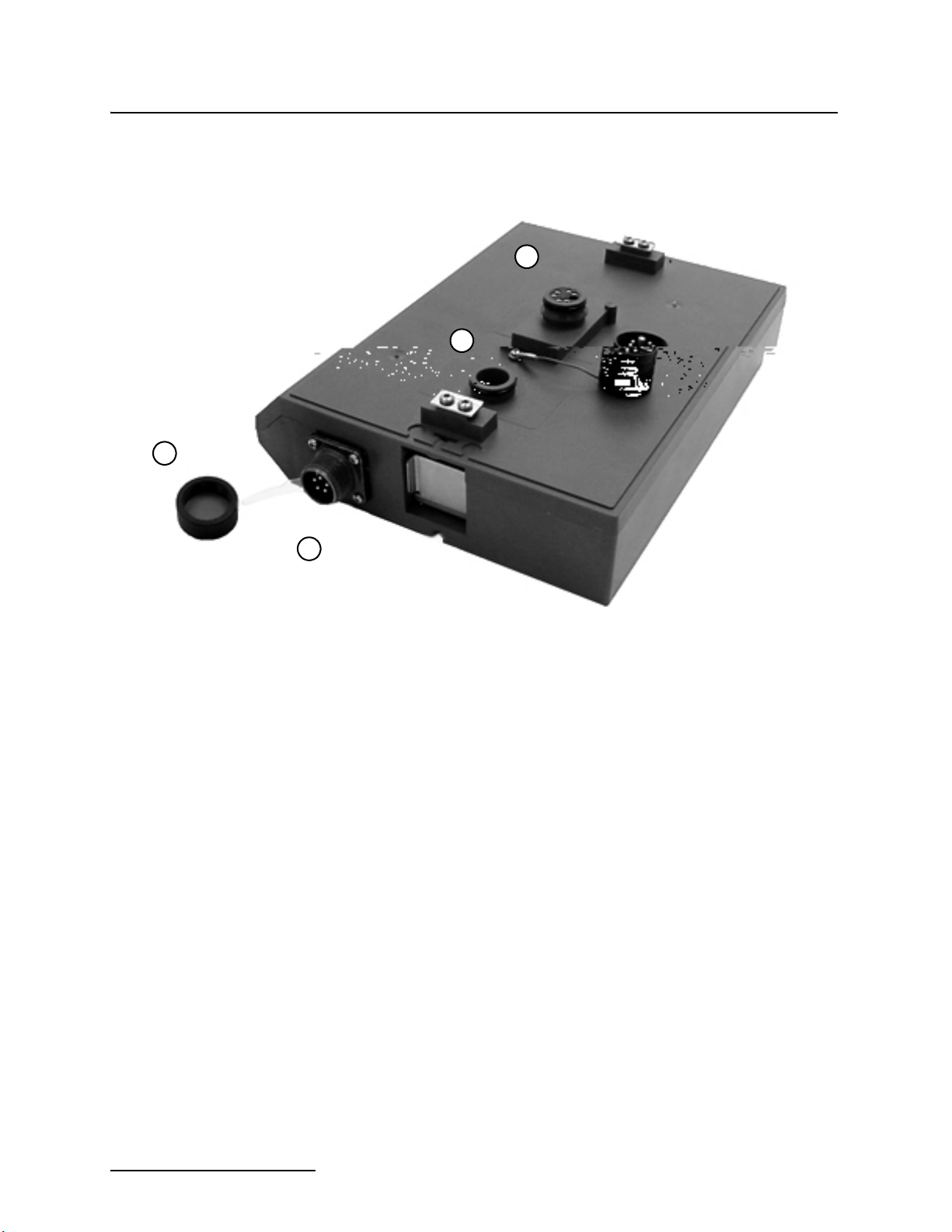
1.3 Identifying Module Components
5
4
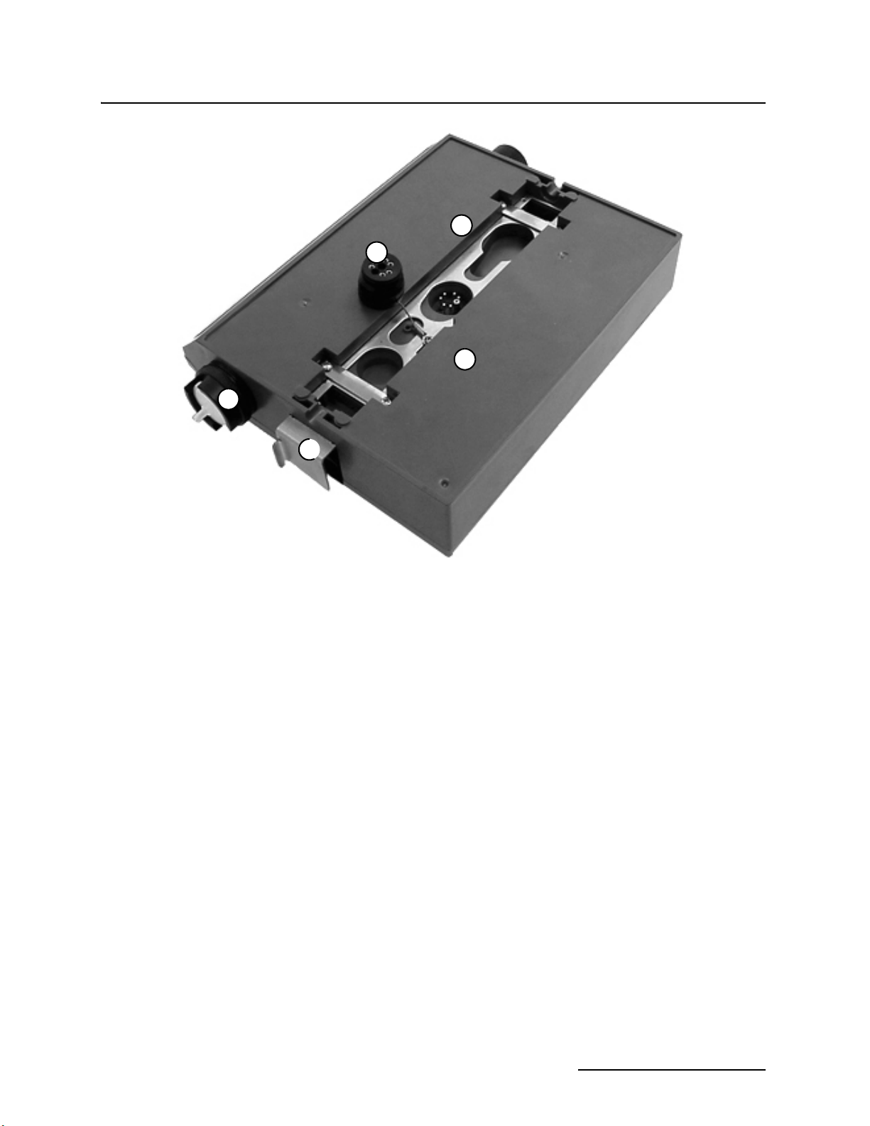
Figures 1-1 and 1-2 identify the key components of the 2103
Modem Module.
1
3
Figure 1-1 2103 Modem Components - Top View
1-2
Page 11
2103 Modem Module
Section 1 Introduction
1
2
3
4
Figure 1-2 2103 Modem Components - Bottom View
1-3
Page 12

2103 Modem Module
Section 1 Introduction
Table 1-3 2103 Modem Module Technical Specifications
Dimensions Length = 10.5 inches (26.7 cm)
Width = 7.5 inches (19 cm)
Height = 2.9 inches (7.4 cm)
Weight 2 lbs. (.9 Kg)
Material High-impact molded polystyrene
Enclosure NEMA 4X, 6P, IP68 (2103), IP67 (2103c)
Power 6.6 to 16.6 VDC, 141 mA typical at 12 VDC, 0.41 mA standby
Operating Temperature -4° to 140°F (-20° to 60°C)
Storage Temperature -40° to 140°F (-40° to 60°C)
Typical Battery Life 291 days*
Modulation Standards Supported
(2103 only)
Communication Speeds Supported 300, 1200, 2400, 4800, 7200, 9600, 12000, 14400, 16800, 19200,
Error Correction Standards Supported V.42 LAPM, MNP-2, MNP-4, MNP-10
Data Compression Standards Supported V.42 bis, MNP-5
Bell 103, Bell 212, V.21, V.22, V.22 bis, V.23, V.32, V.32 bis, V.34
21600, 24000, 26400, 28800, 31200, 33600 bps
* Actual battery life will vary depending upon configuration. The figure given assumes interrogation with Flowlink 4.13 once a week, with a site configu-
ration of a 2103, 2150, and 2191 (using Energizer 529 batteries) and a connection speed of 33600 baud. The 2150 was configured to record level,
velocity, flow rate every 15 minutes, total flow, and battery voltage every 24 hours.
Table 1-4 Specifications – 2191 Battery Module
Size (H×W×D) 6.0 × 9.6 × 7.6 in. 15.2 × 24.4 × 19.3 cm
Weight (without batteries) 3.2 lbs. 1.4 kg
Materials ABS plastic, stainless steel
Enclosure (self-certified) NEMA 4X, 6P IP68
Batteries 6V alkaline lantern or lead-acid lantern, quantity 2
Capacity
Alkaline Lantern Batteries 25 Ahrs
Lead-acid Lantern
Batteries
5 Ahrs
1-4
Page 13
2103 Modem Module
Section 1 Introduction
G
F
A
E
D
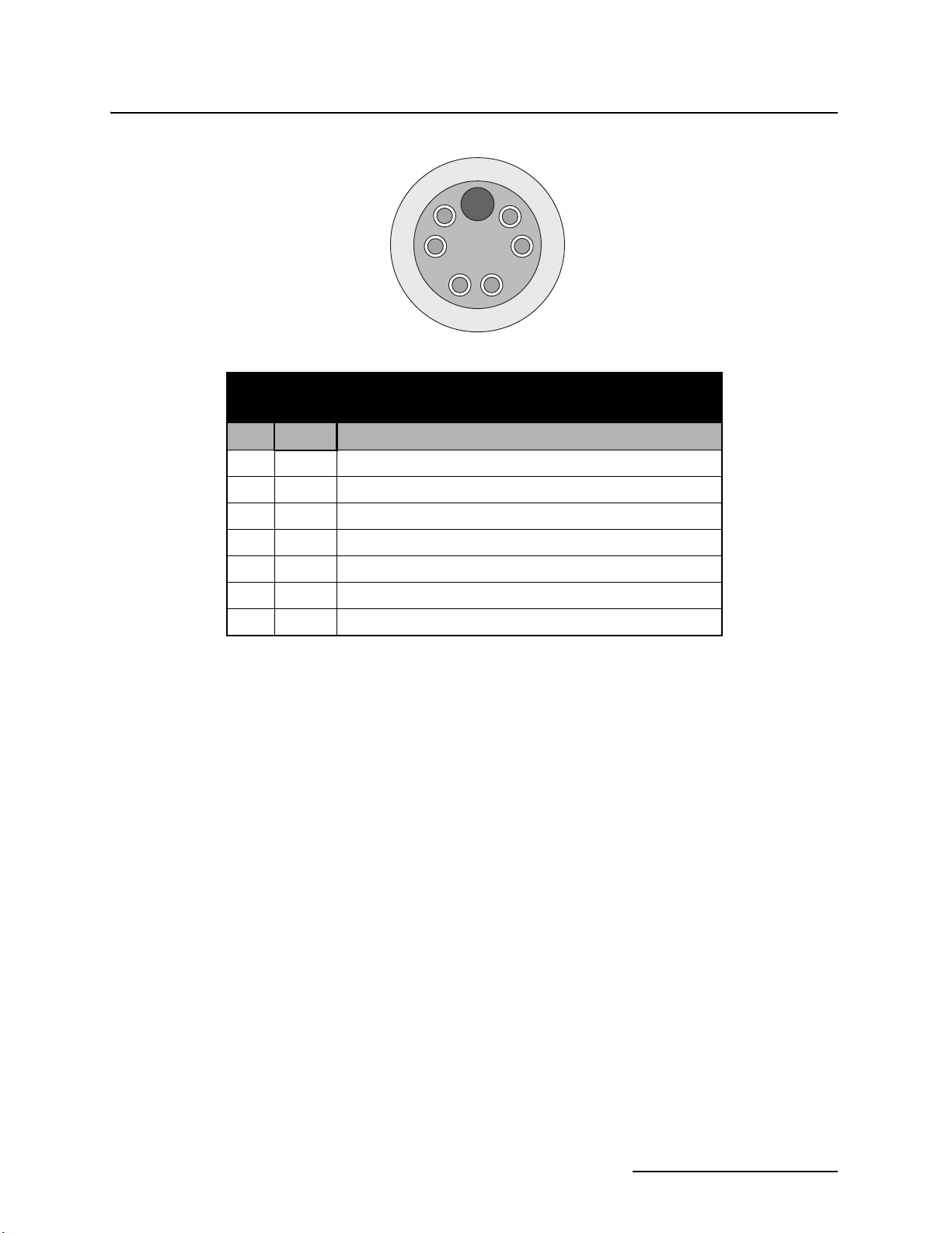
Table 1-5 2103 Communication Connector Pins
(2103 only)
Pin Name Description
A LONA Neuron differential transceiver Data A
B LONB Neuron differential transceiver Data B
C VIN+ Positive power supply voltage input (+12 VDC nominal)
D VIN– Negative power supply voltage input (0 VDC nominal)
E RCVUP PC data receiver inverted input
F XMTUP PC data transmit inverted output
G Key Aligns connector pins
Figure 1-3 2103 Communication Connector Pins
B
C
1-5
Page 14
2103 Modem Module
Section 1 Introduction
Figure 1-4 2103 Modem Cable Connector
1.4 Safety Symbols and Hazard Alerts
This icon identifies a general hazard and is accompanied
with details about the hazard. The instruction manual
identifies the hazardous condition and any steps necessary to correct the condition. The manual presents this information in one of two ways:
CAUTION
Cautions identify a potential hazard, which if not avoided, may
result in minor or moderate injury. This category can also warn
you of unsafe practices, or conditions that may cause property
damage.
WARNING
Warnings indicate potentially hazardous conditions. If you
do not avoid these risks, they could cause you death or
serious injury.
1-6
Page 15

2103 Modem Module
Section 1 Introduction
1.5 Technical Service Although Teledyne Isco designs reliability into all of its
equipment, there is always the possibility of a malfunction
occurring. You can use this manual to help in diagnosing and
repairing any malfunctions. If the malfunction persists, call or
write the Teledyne Isco Technical Service Department for assistance:
Teledyne Isco Inc.
Technical Service Department
P.O. Box 82531
Lincoln, NE 68501
800-228-4373 or 402-464-0231
FAX: 402-465-3001
e-mail: IscoService@teledyne.com
Simple difficulties can often be diagnosed over the phone. If it is
necessary to return the equipment to the factory for service,
please follow the shipping instructions provided by the Technical
Service Department, including the use of the Return Authorization Number specified. Be sure to include a note describing the
malfunction. This will aid in the prompt repair and return of the
equipment.
1-7
Page 16

2103 Modem Module
Section 1 Introduction
1-8
Page 17

2103 Modem Module
Section 2 Installation and Operation
2.1 Unpacking Instructions
Teledyne Isco, Inc.
Customer Service Dept.
P.O. Box 82531
Lincoln, NE 68501 USA
Phone: (800) 228-4373
Outside USA & Canada call:
(402) 464-0231
FAX: (402) 465-3022
E-mail: IscoCSR@teledyne.com
2.2 Safety
When the system arrives, inspect the contents for any damage. If
there is damage, contact the delivery company and Teledyne Isco
(or its agent) immediately.
WARNING
If there is any evidence that any items may have been
damaged in shipping, do not attempt to install the unit.
Please contact Teledyne Isco (or its agent) for advice.
When you unpack the system, check the items against the
packing list. If any parts are missing, contact the delivery
company and Teledyne Isco’s Customer Service Department.
When you report missing part(s), please indicate them by part
number. In addition to the main packing list, there may be other
packing lists for various sub-components.
It is recommended that you retain the shipping cartons as they
can be used to ship the unit in the event that it is necessary to
transport the system.
Please complete the registration card and return it to Teledyne
Isco, Inc.
WARNING
Avoid hazardous practices! If you use these instruments in
any way not specified in this manual, the protection
provided by the instruments may be impaired; this will
increase your risk of injury.
WARNING
The installation and use of this product may subject you
to hazardous working conditions that can cause you
serious or fatal injuries. Take any necessary precautions
before entering a worksite. Install and operate this product
in accordance with all applicable safety and health
regulations, and local ordinances.
The 2100 Series components are often installed in confined
spaces. Some examples of confined spaces include manholes,
pipelines, digesters, and storage tanks. These spaces may become
2-1
Page 18
2103 Modem Module
Section 2 Installation and Operation
hazardous environments that can prove fatal for those unprepared. These spaces are governed by OSHA 1910.146 and require
a permit before entering.
2.3 Installation Follow the instructions below to install your 2103 Modem. Most
of these instructions are similar for the 2103
you have one of those modules, read Section 3 or 4 for additional
installation information.
C and 2103G, but if
2.3.1 Latches - Locking and Unlocking
2.3.2 Communication Connectors
Latches must be operated to stack and unstack the modules in a
Series 2100 stack. The mechanisms are the same for the 2103
Modem and other 2100 Series modules. Detailed instructions
with photos can be found in your 2150 instruction manual.
Take a moment to familiarize yourself with operating the latches.
You must unlock the latch to place the module on top of another
module in a stack. The latch is unlocked by pushing in the latch
release on the right side of the module. To lock the latch, push in
the latch on the left side of the module.
CAUTION
The latch can be damaged by applying too much force. Never
press on both sides at the same time. Do not force the latch if it
is obstructed. While some degree of pressure must be applied
to slide the latch, the ends of the latches should never bend
more than
1
/8”.
Note
Latches will “click” when they are fully locked and unlocked.
Connecting the 2103 Modem module involves uncapping and
capping communication connectors. When a communication connector is not in use, the connector should always be capped. The
cap will seal the connector to prevent corrosion, and will improve
communications.
When a communication connector is in use, store the cap on the
holder next to the connector. The communication connector will
be sealed by its mating connector.
Detailed instructions and photos can be found in your 2150 or
2110 instruction manual.
2-2
CAUTION
Caps PUSH ON and PULL OFF. Do not rotate the caps to
remove them from the connectors.
Note
For modules to correctly stack and lock together, protective
caps between the modules must be stored on the holders.
Page 19

2103 Modem Module
Section 2 Installation and Operation
2.3.3 Stacking Modules The 2103 Modem Module can be located anywhere within a stack
of up to three 2100 Series networked modules. It will draw its
power from the battery module located in the stack.
To connect the 2103 with a 2100 Series module, refer to the following instructions.
1. On the top of the 2100 Series module, remove the cap and
stow it on the holder. This exposes the communication connector on the module.
2. Inspect the module’s communication connector. It should
be clean and dry. Damaged O-rings must be replaced.
3. Unlock the 2103’s latch by pressing in on the latch release
(right side).
4. Underneath the 2103, remove the cap from the lower communication connector and stow it in the holder.
5. Lock the latch. Locking the latch correctly seats and aligns
the lower cap in its holder.
6. Position the 2103 over the 2100 Series module. Align the
connectors and lower the 2103 onto the other module.
7. Unlock the 2103’s latch by pressing in on the latch release
(right side).
8. Firmly press the modules together and lock the 2103’s
latch (left side).
The communications indicator will blink during the start-up
routine to indicate the 2103 is operating.
2.4 Telephone Line Connection (2103 only)
The FCC (Federal Communications Commission) governs communications over telephone lines. Your local telephone company
will provide you with the line between the 2103 Modem and your
computer. Contact them for connection information.
The 2103 Modem is in compliance with FCC part 68 rules.
However:
Note
In tests conducted by the Communication Certification Laboratory, the 2103 Modem did not pass conducted RF testing on
telephone line at 5 MHz, 3V RMS. For details, see international
standard EN 61000-4-6.
In the event of this failure, the modem may be subject to disconnection.
Accordingly, the FCC requires the following information
be published:
Note
The 2103 Modem is designed to be used on standard device
telephone lines. It connects to the telephone by means of a
standard jack called the USOC RJ-11C. Connection to telephone-company-provided coin service (central office implemented systems) is prohibited, and connection to party lines
2-3
Page 20

2103 Modem Module
Section 2 Installation and Operation
service is subject to state tariffs.
Changes in Attestation Procedure for Plugs and Jacks
Isco Inc. attests that the network interface plugs or jacks used
on this equipment comply with and will continue to comply with
the mechanical requirements specified in Part 58, sub-part F,
specifically the dimensions, tolerances and metallic plating
requirements. The compliance of these connectors will be
assured by purchase specifications and incoming inspection.
Documentation of such specifications and/or inspections will
be provided to the FCC within 30 days of their request for the
same.
Telephone Company Procedures
The goal of the telephone company is to provide you with the
best service it can. In order to do this, it may occasionally be
necessary for them to make changes in their equipment, operations or procedures. If these changes might affect your service or the operation of your equipment, the telephone
company will give you notice, in writing, to allow you to make
any changes necessary to maintain uninterrupted service.
In certain circumstances, it may be necessary for the telephone company to request information from you concerning
the equipment which you have connected to your telephone
line. Upon request of the telephone company, provide the FCC
registration number and the ringer equivalence number (REN);
both of these items are listed on the equipment label. The sum
of all the RENs on your telephone lines should be less than
five in order to assure proper service from the telephone company. In some cases, a sum of five may not be usable on a
given line. Consult your telephone provider.
If Problems Arise: If any of your telephone equipment is not
operating properly, you should immediately remove it from your
telephone line, as it may cause harm to the telephone network.
If the telephone company notes a problem, they may temporarily discontinue service. When practical, they will notify you in
advance of this disconnection. If advance notice is not feasible,
you will be notified as soon as possible. When you are notified,
you will be given the opportunity to correct the problem and will
be informed of your right to file a complaint with the FCC. Contact your local telephone service provider if you have any questions about your phone line.
In the event repairs are needed on the 2103 Modem, they
should be performed by Teledyne Isco Inc. or its authorized
representative. For information, contact the Teledyne Isco Customer Service Department at (800) 228-4373 or (402)
464-0231.
2-4
Page 21

2103 Modem Module
Section 2 Installation and Operation
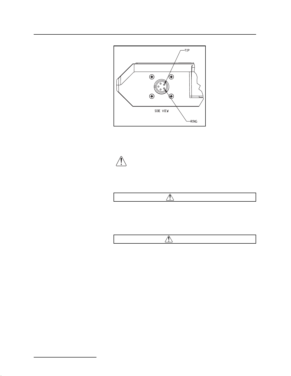
2.4.1 Modem Cable Connection
After you have installed the 2103 on the stack, you need to attach
the modem cable so the module can be connected to a phone line.
Remove the connector cap from the 5-pin circular modem cable
connector on the right hand side of the 2103. Attach the modem
cable to the connector (Figure 2-1), and then connect the other
end of the modem cable to a standard telephone jack (USOC
RJ-11C).
Figure 2-1 Connecting the Modem Cable
2.4.2 Connection Without the Modem Cable
Figure 2-2 2103 Modem Cable Connector
If desired, the 2103 can be connected to a standard telephone line
by attaching the telephone line cable to a connector that mates
with the 2103’s 5-pin circular modem cable connector (Figure
2-2). Be sure that you have a water tight seal on your wire connections.
For your reference, the modem cable uses a 5-pin amphenol
socket, MS3106A-5S.
2-5
Page 22
2103 Modem Module
Section 2 Installation and Operation
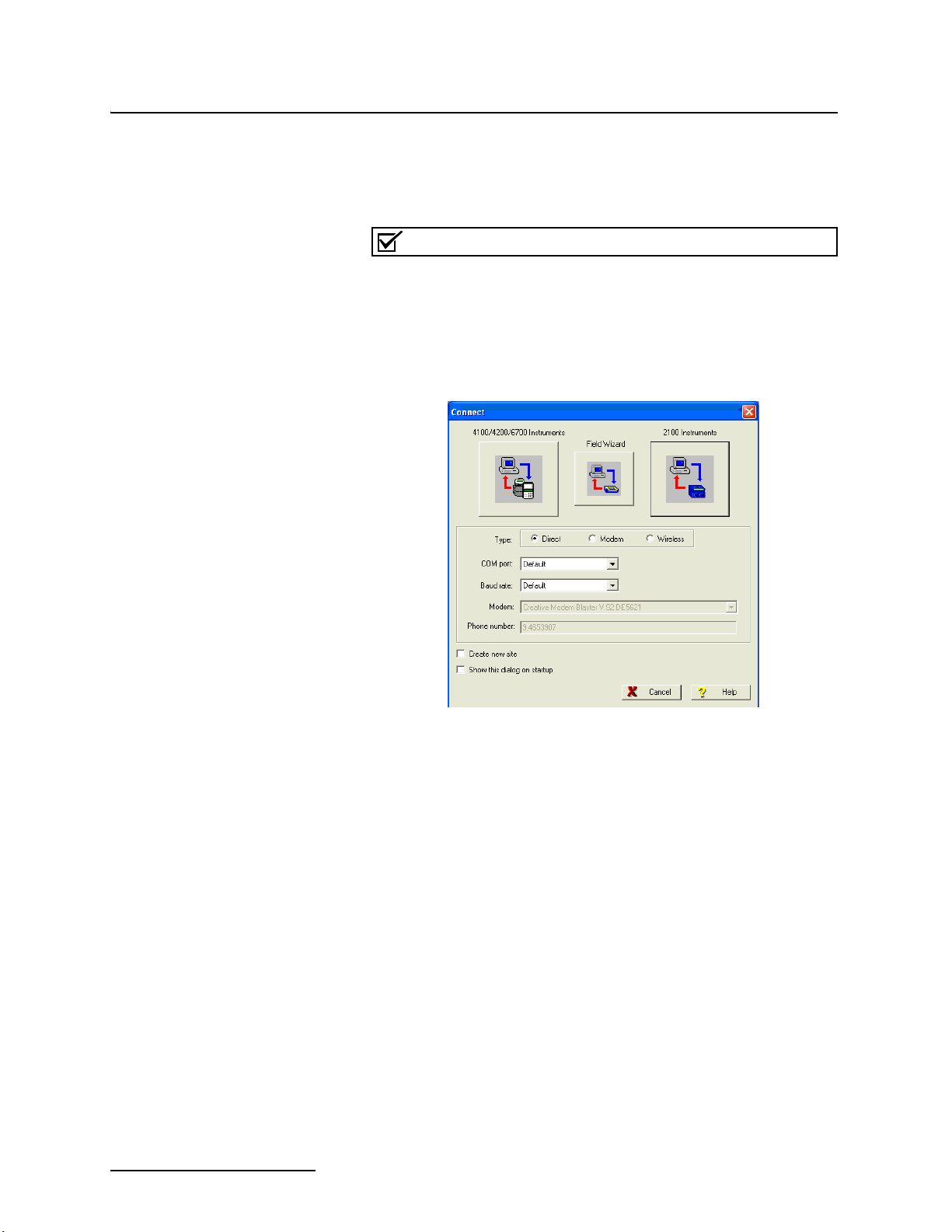
2.5 Connecting to Flowlink
After the 2103 is installed and the modem cable connected, you
need to establish that there is a modem at the site, by configuring the module in Isco’s Flowlink software.
Note
The 2103 Modem requires Flowlink 4.13 or later. Earlier versions do not support the modem.
Open Flowlink and go to the connect screen (Figure 2-3) by either
selecting it from the pull down menu or clicking on the Quick
Connect icon.
Figure 2-3 Flowlink Connect Screen
2-6
Make sure the Type is Direct, and click on the 2100 Instrument
icon to connect. The system will detect a new modem module, and
will display the Network Resolution screen (Figure 2-4).
Page 23
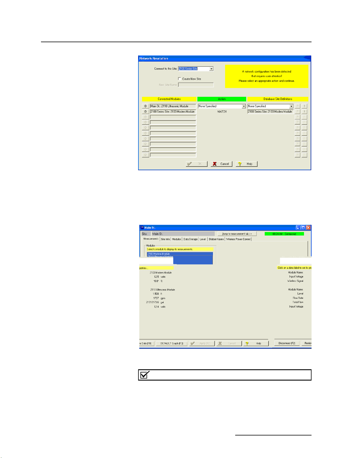
Figure 2-4 Resolution Screen
2103 Modem Module
Section 2 Installation and Operation
Select the appropriate action on the screen to add the new
modem module and then click OK. When the module has been
added to the system, you will see the Measurements Screen
(Figure 2-5).
Figure 2-5 Measurements Screen
Note
If you are using a 2103C or 2103G, you need to set up a Wireless Power Control schedule at this point. For those instructions, refer to Sections 3-3 or 4-5.
2-7
Page 24

2103 Modem Module
Section 2 Installation and Operation
Figure 2-6 Site Info Screen
Click on the Site Info tab to display that screen (Figure 2-6).
2.5.1 Setting Up Text Messaging
Select Modem under the Connection Information section. Enter
the phone number to be used by the modem to connect to the site.
Click Apply (F9) to apply the changes.
To program the 2103 for text messaging, you must have the Telocator Alphanumeric Protocol (TAP) server number and
parameter settings of your cell phones and/or pagers.
1. Make sure you are connected to the site, and select the
Dialout Alarms tab (Figure 2-7).
Figure 2-7 Setting dialout phone numbers and alarm conditions
2-8
Page 25

2103 Modem Module
Section 2 Installation and Operation
2. In the Phone Number list box, type the contact telephone
numbers. These must be valid TAP access numbers. You
must enter at least one number; you can enter as many as
five. When an alarm condition is triggered, the system will
try dialing each phone number in the list.
a. To find this number, and the communications parame-
ter settings, consult with your pager service, or go to
http://www.avtech.com/Support/TAP/index.htm
or to
http://www.notepage.net/tap-phone-numbers.htm.
b. With either online location, click the letter correspond-
ing with the first letter of the name of your service provider. You will advance to a screen that shows your
service provider, the access number, and parameter values (Figure 2-8).
TAP service
number and
parameter
values
Figure 2-8 TAP Service Parameters
3. For each phone number entered, enter a Pager ID, which is
the phone number of the cell phone or pager that will
receive the text message. (The ID will come from your
pager service.)
4. You have the option of entering a password of up to six
characters in length.
5. In the Comm field, select 7E1 or 8N1for the communications control specification (your pager service has this
information).
6.
You must enter a message to be sent to the pager. In the field
labeled Message,
type the outgoing text message (maximum
of 32 characters).
7. Under “Alarm condition”, select the desired alarm parameter from the drop-down list, then define the alarm conditions.
8. Click the Apply button or press F9 when you are done, to
update the module’s settings.
2-9
Page 26
2103 Modem Module
Section 2 Installation and Operation
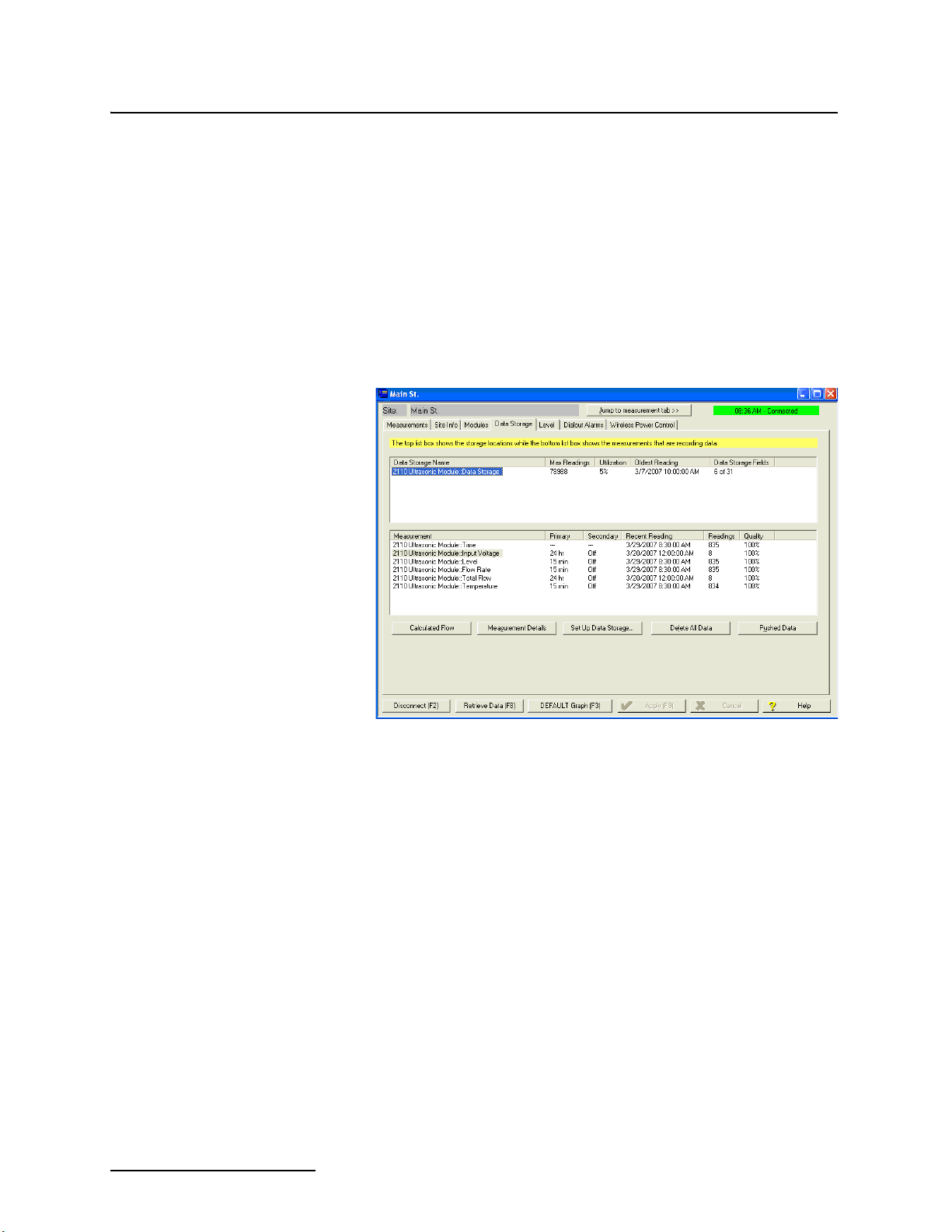
2.6 Pushed Data Capability
The module can automatically send data to a designated server
running Isco Flowlink Pro software, using 1xRTT
packet-switched data transmission (2103
packet-switched data transmission (2103
(2103). The user-specified primary data transmission interval (5
minutes to 24 hours) can automatically change to a secondary
interval when specific site conditions occur at the monitoring
site. An Oracle® or Microsoft® SQL database is required to use
this feature. Contact the factory for additional information.
To use the data push capability, you need to make sure you are
connected to the modem module, and then select the Data
Storage tab (Figure 2-9).
G), or a land line modem
C ), GPRS
Figure 2-9 Data Storage tab
2-10
Click on the Pushed Data button to set up a schedule for the data
to be pushed to Flowlink Pro.
Detailed Flowlink instructions are beyond the scope of this
manual. Flowlink’s operating instructions are available in a
Windows Help format. You can access the help topics for an
active window by clicking on its Help button or by pressing F1 on
your computer’s keyboard. You can also access Help topics by
selecting Help from the Flowlink menu.
Page 27

2103 Modem Module
Section 3 2103C Cellular Modem Module
3.1 Overview The 2103C Modem (part #68-2000-033 with a magnetic mount
antenna; part #68-2000-030 with an in-street antenna) is a portable data retrieval unit designed to transmit data from Isco’s
2100 Series open channel flow modules.
3.1.1 Data Retrieval Using a computer running Isco’s Flowlink® software, you can call up your monitoring site to configure the flow module settings and retrieve flow data.
Detailed operating instructions are available in Flowlink in a
Windows Help format, and in the flow module’s Installation and
Operation Guide.
3.1.2 Text Messaging Using CDMA technology, the 2103 saging to up to 5 text capable cellular phones or pagers when a programmed alarm condition occurs.
Consult the Flowlink Help files and Installation and Operation
Guide for details on programming alarm conditions.
3.1.3 Stacking /
Compatibility
3.1.4 Cellular Service The 2103C only works in a CDMA cellular service area for CSD
The 2103
modules, or used remotely, powered by an Isco 2191 battery
module. The 2103
flow module, 2110 Ultrasonic flow module, 2101 Field Wizard,
and 2102 Wireless module.
operation.
Not all CDMA service areas have 1xRTT service. See your local
CDMA service provider for service availability.
C can be located anywhere within a stack of 2100 Series
C is compatible with Isco’s 2150 Area Velocity
C is capable of digital text mes-
3-1
Page 28

2103 Modem Module
Section 3 2103C Cellular Modem Module
3.2 Antenna Options One of 2 antenna types is included with your system, also spec-
ified when ordering:
•The external, magnetic mount antenna (part
#68-2000-032) is 3 inches tall and has a 6 foot cable.
This antenna is for general use, and is especially
desirable when the system is stored within an enclosure.
Figure 3-1 2103
Figure 3-2 2103
C magnetic mount antenna
•The external, in-street antenna (part #68-2000-031) is
4” in diameter and 1.75” tall, with a 10 foot long cable. It
is used primarily in manhole applications.
The antenna is buried next to the manhole, in a hole
bored into the pavement, at a depth leaving the top of
the antenna flush with the street.
A connecting hole is drilled through the manhole collar
for the antenna’s cable. To complete the installation, fill
the holes in with cement.
C buried antenna
3.2.1 Connecting the Antenna
3-2
The antennas are connected to the 2103
C using the connector on
the right hand side of the module.
The two types of antennas use a protective connector shell on the
end of the cable to protect the end connector from the elements.
On the magnetic mount antenna, this connector shell is installed
at the factory. If you order an in-street antenna, the shell is left
off to make it easier to install the buried antenna.
Page 29

Section 3 2103C Cellular Modem Module
When you are ready to connect the in-street antenna to the
2103
C modem, you will need to assemble the connector shell onto
the end of the cable. The pieces of the connector shell are shown
in Figure 3-3. An instruction sheet (P/N 60-2003506) is shipped
with the antenna, and shows you the assembly steps.
Figure 3-3 Protective connector shell pieces for the in-street antenna
2103 Modem Module
To connect an antenna to the 2103
nector shell (Figure 3-4) to loosen its components. Slide the components down the cable to reveal the gold connector end.
Twist the connector
shell to loosen its
components.
Slide the components
down the cable, and
connect the gold
connector end to the
modem.
Figure 3-4 Connecting an antenna to the 2103
C, twist the protective con-
C
3-3
Page 30

2103 Modem Module
Section 3 2103C Cellular Modem Module
When the gold SMA connector is tightly attached to the modem,
slide the connector shell forward. Press down on the metal latch
on the side of the modem and push the connector shell onto the
modem, as shown in Figure 3-5.
Figure 3-5 Antenna connected to the 2103C modem.
Note
When any communication connector is not in use, it should
always be capped. The cap will seal the connector to prevent
corrosion, prevent moisture from entering the unit, and improve
communications.
Note
For the transmitter to comply with FCC Maximum Permissible
Exposure (MPE) regulations, the antenna needs to be located
a minimum of 30 centimeters (12 inches) from the human
body.
3-4
Page 31

2103 Modem Module
Section 3 2103C Cellular Modem Module
3.3 Connecting to Flowlink
The instructions for connecting to Flowlink that are in Section
2-5 apply to the 2103
to set up a Wireless Power Control schedule.
Select the Wireless Power Control tab (Figure 3-4) and click on
the Set Wireless Schedule button to set up a schedule.
C. However, for the 2103C, you will also need
Figure 3-6 Wireless Power Control screen
In the Wireless Schedule screen (Figure 3-5), enter the type of
schedule and its start and stop times. Press OK when done.
Figure 3-7 Wireless Power Schedule screen
3-5
Page 32

2103 Modem Module
Section 3 2103C Cellular Modem Module
3-6
Page 33

2103 Modem Module
Section 4 2103G Cellular Modem Module
4.1 Overview The 2103G Modem (part #68-2000-042 with a magnetic mount
antenna; part #68-2000-041 with an in-street antenna) is a portable data retrieval unit designed to transmit data from Isco’s
2100 Series open channel flow modules.
4.1.1 Data Retrieval Using a computer running Isco’s Flowlink® software, and the appropriate cellular service, you can call up your monitoring site to configure the flow module settings and retrieve flow data.
Detailed operating instructions are available in Flowlink in a
Windows Help format, and in the flow module’s Installation and
Operation Guide.
4.1.2 Text Messaging Using GSM technology, and with the appropriate SIM card, the 2103
G is capable of digital text messaging to up to 5 text capable
cellular phones or pagers when a programmed alarm condition
occurs.
Consult the Help files and Installation and Operation Guide for
details on programming alarm conditions.
4.1.3 Stacking /
Compatibility
The 2103
modules, or used remotely, powered by an Isco 2191 battery
module. The 2103
flow module, 2110 Ultrasonic flow module, 2101 Field Wizard,
and 2102 Wireless module.
G can be located anywhere within a stack of 2100 Series
G is compatible with Isco’s 2150 Area Velocity
4.2 SIM Card The data transmission capabilities of the 2103G are dependent
upon the type of service plan you have through your cell phone
service provider. The service parameters, or provider, can be
changed by simply replacing the Subscriber Information Module
(SIM) card in your 2103
verify what data transmission technologies are available for your
use.
To access the SIM card slot, turn the 2103
bottom is a round metal cover that, when unscrewed, provides
access to the card (Figure 4-1).
G. Check with your service provider to
G module over. On the
4-1
Page 34

2103 Modem Module
Section 4 2103G Cellular Modem Module
Figure 4-1 Accessing the SIM card on the bottom of the module
It’s easiest to insert the SIM card if you set the module on its side
(Figure 4-2) and push the card into its slot as shown. To remove
the card from its slot, push on it and it will pop out enough that
you can grasp the end and pull it out.
Figure 4-2 Inserting the SIM card into the module
After inserting the card, slide the internal lock (next to the slot
for the SIM card) to the locked position, to make sure the SIM
card stays in place. Then reinstall the metal cover on the bottom
of the module.
4-2
Page 35

2103 Modem Module
Section 4 2103G Cellular Modem Module
4.3 Antenna Options One of 2 antenna types is included with your system, also spec-
ified when ordering:
•The external, magnetic mount antenna (part
#68-2000-047) is 6 feet long and 5 inches tall. This
external antenna is for general use, and is especially
desirable when the system is stored within an enclosure.
Figure 4-3 2103
Figure 4-4 2103
G with a magnetic mount antenna
•The external, in-street antenna (part #68-2000-031) is
10 feet long, and used primarily in manhole applications.
The antenna is buried next to the manhole, in a hole
bored into the pavement, at a depth leaving the top of
the antenna flush with the street.
A connecting hole is drilled through the manhole collar
for the antenna’s cable. To complete installation, fill the
holes in with cement.
G with an in-street antenna
4.3.1 Connecting the Antenna
The antennas are connected to the 2103
G using the connector on
the right hand side of the module.
The two types of antennas use a protective connector shell on the
end of the cable to protect the end connector from the elements.
On the magnetic mount antenna, this connector shell is installed
at the factory. If you order an in-street antenna, the shell is left
off to make it easier to install the buried antenna.
4-3
Page 36

2103 Modem Module
Section 4 2103G Cellular Modem Module
When you are ready to connect the in-street antenna to the
2103
G modem, you will need to assemble the connector shell onto
the end of the cable. The pieces of the connector shell are shown
in Figure 4-5. An instruction sheet (P/N 60-2003506) is shipped
with the antenna, and shows you the assembly steps.
Figure 4-5 Protective connector shell pieces for the in-street antenna
To connect an antenna to the 2103
nector shell (Figure 4-6) to loosen its components. Slide the components down the cable to reveal the gold connector end.
Twist the connector
shell to loosen its
components.
Slide the components
down the cable, and
connect the gold
connector end to the
modem.
Figure 4-6 Connecting an antenna to the 2103
When the gold SMA connector is tightly attached to the modem,
slide the connector shell forward. Press down on the metal latch
on the side of the modem and push the connector shell onto the
modem, as shown in Figure4-7.
G, twist the protective con-
G
4-4
Page 37

2103 Modem Module
Section 4 2103G Cellular Modem Module
Figure 4-7 Antenna connected to the 2103
When any communication connector is not in use, it should be
capped. The cap will seal the connector to prevent corrosion,
prevent moisture from entering the unit, and improve communications.
For the transmitter to comply with FCC Maximum Permissible
Exposure (MPE) regulations, the antenna needs to be located
a minimum of 30 centimeters (12 inches) from the human
body.
G modem.
Note
Note
4-5
Page 38

2103 Modem Module
Section 4 2103G Cellular Modem Module
4.4 Connecting to Flowlink
The instructions for connecting to Flowlink that are in Section
2-5 apply to the 2103
need to set up a Wireless Power Control schedule.
G. However, for the 2103G, you may also
Note
This section only applies to CSD operation, and requires the
appropriate cellular service and SIM card.
Select the Wireless Power Control tab (Figure 4-6) and click on
the Set Wireless Schedule button to set up a schedule.
Figure 4-8 Wireless Power Control screen
In the Wireless Schedule screen (Figure 4-7), enter the type of
schedule and its start and stop times. Press OK when done.
Figure 4-9 Wireless Power Schedule screen
4-6
Page 39

2103 Modem Module
Section 4 2103G Cellular Modem Module
4.5 Setting Up The Access Point Name
You may need to set up the access point that your cellular service
uses.
Note
This section only applies to GPRS operation, and requires the
appropriate cellular service and SIM card.
The access point information is available from your service provider.
1. From your Windows desktop, start the HyperTerminal program (located under Accessories, Communication).
2. Make sure the 2103
nal is disconnected. Select the COM port you will direct
connect to.
3. Configure the COM port to: 38400 bps, 8 data bits, no
parity, no stop bits, no flow control. Click OK.
4. Click on the phone icon to connect, and enter 3 or 4 question marks (?).
5. At the > prompt, enter sp and press Return.
6. At the > prompt, enter 18 and press Return.
7. At the DPUSH> prompt, enter apn and press Return.
This will display the current setting for the access point
name.
8. If you need to change the access point name, at the >
prompt, enter apn “name of access point” and press
Return.
9. You will be informed that the phone network information
has been updated.
10. Cycle power to the modules.
G is powered on, and that HyperTermi-
There are several commands that can be used in HyperTerminal.
The >dcfg command will show what IP address you should be
using. The >dsp command shows the network type (GSM) and
the access point name.
4-7
Page 40

2103 Modem Module
Section 4 2103G Cellular Modem Module
4-8
Page 41

2103 Modem Module
Section 5 Modbus Protocol
Sections 5.1 through 5.5 give an overview of the basic capabilities
and operation of Modbus protocol as it applies to Isco 2100 Series
flow modules.
For a Glossary of Terms and Common Acronyms, see sections 5.4
and 5.5.
For Modbus technical specifications, turn to section 5.6.
5.1 Introduction Modbus is a simple command/response mechanism to read from
and write to specific memory locations called registers. A register
is a holding place for a piece of digital information within the
equipment. There are three standard protocols for Modbus:
Modbus RTU, Modbus TCP/IP, and Modbus ASCII. The Isco 2100
Series devices use Modbus ASCII protocol, the metho [(vwssme)-4.6d0
asemoe flexibflecommuhniaction
.47.9( Modb)586(u)-5.4(s34.2( )]TJ1453601 0 TD0.1642 Tc0.0291 Tw[commuhniactio( fortThe Isco(2100)]TJ-1453601 -1.2048 TD0.1014 Tc[(Ser )6.1ies(prvidiesao )-6st(andard )-6(protoco )]TJ)6.2289 0 TD0.0097 Tc0.0056 Tw[rtTate)-4.9(cand )-6be( ueds )-6(tore(tr)-4.1(eve0)]TJ-)6.2289 -1.2048 TD0.0015 Tc0.000 Tw[(rall)48(-ati)48(mi)0.5(s )6da.47.9tas singllee .47.9cw moulle(itr)2126(,)]TJT*0.3027 Tc0.2656 Tw[formulatipali(e)-349( si)4.3(ens)2586(,)-2.6 ov wsira. Thedata.4749(candbl)4.4(e)-349( )6(mene t)2(o)-349(a,)]TJT*0.002 Tc-0..021 Tw[cmenralecompuste( for[(pla)9586yP)19349,edata.
Modbat10.7(ionius )6(in)-5.2dependwin
5-1
Page 42

2103 Modem Module
Section 5 Modbus Protocol
By accessing these registers you can obtain the current value of
whatever parameter you desire. The reading(s) can then be displayed or stored wherever you designate as a destination; for
example, a process control computer.
Note
Level, flow, velocity, and temperature data is stored in metric
units only.
Not all registers are limited to read-only data storage. You can
also use some registers for control purposes. For example, by
writing a “1” value to register 24 (“Identify Module” register), you
will tell a 2100 module to light the LED on the front of the
module.
5.2.1 Establishing Communication
5.2.2 Module Addressing When connecting to a site via a Modbus OPC server, you use a
There are several different communications protocols supported
in the 2100 series that require auto-baud rate detection. Because
of this, each time a modbus connection is made, the module uses
a polling mechanism to repeatedly send a command until a
response is received. It may take up to 20 command retries
before the module has identified the baud rate and a response is
received.
dedicated line of communication to that module or stack from the
OPC server, which can be a dedicated communications cable
(direct connection) or a dedicated phone number (modem).
When you are using a direct connection, you are dedicating a
specified COM port on the computer, and that COM port determines the site to which you are connecting.
When you are using a modem, the dedicated line is defined by
the site's phone number.
If you connect more than one 2100 Series module at a site, the
Modbus OPC server, while using the shared communication line
for all of the modules within the network, must have some way to
differentiate between the modules. When sending a command to
a specific module, the command has an address field. This allows
the server software to talk to, as well as control, the specified
module, while ignoring other modules in the same stack or site.
Each module capable of Modbus Protocol communication will
automatically create its own specific ASCII address within the
site, using:
• The model numbers of the modules
• The user-defined module names
5-2
Page 43

2103 Modem Module
Section 5 Modbus Protocol
5.3 Configurations A variety of configurations can be made with Modbus, either
through direct connection or through a modem.
In the example shown in Figure 5-1, you are direct-connecting a
server PC to two individual 2150s through Modbus, using the
COM ports on the OPC Server, which are directly connected to
the remote 2150s.
Connection to the module is made through the RS-232 communication port on the top of the module.
Note
For low power operation, we recommend connecting the module(s) to the computer using the straight-through cable (Isco
part number 60-5314-529), which consumes less power,
instead of our standard interrogation cable.
In Figure 5-1, the OPC Server PC must have two COM ports.
Modbus requires one COM port each, for direct connection of
each 2150.
2150
2150
Figure 5-1 Configuration Example (Direct Connection Shown)
The operation sequence for the example above can be summarized in the following steps:
2150:
1. 2150s take readings from probes.
2. 2150s store readings (level, velocity, flow rate, etc.) in their
specified registers.
Process Control:
3. The user requests data through Process Control.
4. Process Control asks the OPC server to gather information.
COM
port 1
COM
port 2
OPC
Server
Process
Control
5-3
Page 44

2103 Modem Module
Section 5 Modbus Protocol
5. OPC connects to the 2150 stack through the cable (direct
connection), takes register data from the specified 2150,
and populates the OPC server's holding index.
6. Process Control takes data from the OPC server's holding
index and gives data to the user.
Note that Process Control can be either manual or automated in
this example, and that the OPC server and Process Control may
be located physically on the same computer.
5.4 Glossary of Terms ASCII – Short for American Standard Code for Information
Interchange, ASCII is a code that represents English characters
with numbers. Most computers represent text with ASCII code,
making it possible for one computer or device to share data with
another.
2100 modules support Modbus ASCII protocol.
Dedicated Line – A telecommunications path reserved for communication between two specified points and not shared among
multiple points.
Modbus Protocol – Modbus Protocol is a messaging structure
used to establish master-slave/client server communications
between intelligent devices. Modbus is a simple
command/response mechanism to read from and write to registers.
OPC – OPC (OLE for Process Control) means open connectivity
via open (free for use) standards. It is a series of software standards specifications that fill a need in automation (like printer
drivers did for Windows), acting as a translator for data transmission and process control.
The specification defines a standard set of objects, interfaces, and
methods for use in process control and manufacturing automation applications to facilitate interoperability. There are hundreds of OPC Data Access servers and clients.
Registers – Registers are locations in memory that have specific
data stored for retrieval or are used for control functions. A register is a holding place for a piece of digital information within
the equipment. The definition of what is contained and where
(the registry number, or address) is decided by the manufacturer
(in this case Teledyne Isco).
SCADA – SCADA (Supervisory Control And Data Acquisition)
is a computer system for gathering and analyzing real-time data.
SCADA systems are used to monitor and control plant operation,
or equipment in industries such as telecommunications, water
and waste control, energy, oil and gas refining, and transportation.
The SCADA system transfers the information (for example,
where a leak has occurred in a pipeline), back to a central site,
alerting the home station of the leak, performing necessary
analysis and control (such as determining if the leak is critical),
and displaying the information in a logical and organized
manner.
5-4
Page 45

2103 Modem Module
Section 5 Modbus Protocol
SCADA systems can be relatively simple, such as one that monitors the environmental conditions of a small office building, or
very complex, such as a system that monitors all the activity in a
nuclear power plant or a municipal water system.
5.5 Common Acronyms ASCII – American Standard Code for Information Interchange
DCS – Distributed Control Systems
MTU – Master Terminal Unit
OPC – Object Linking and Embedding (OLE) for Process Control
PLC – Programmable Logic Controller
RTU – Remote Terminal Unit
SCADA – Supervisory Control And Data Acquisition
TCP/IP – Transmission Control Protocol/Internet Protocol
5-5
Page 46

2103 Modem Module
Section 5 Modbus Protocol
5.6 Register Specifications All numbers in the Modbus registers are stored most significant
byte first. If the polling device has a byte ordering of least significant byte first (an Intel-based PC, for example), the bytes will
need to be reversed after they are received.
The Modbus ASCII address is used to index the data by modules.
Modbus ASCII address 1 contains information related to the site.
The first register contains a 16-bit integer count of the number of
modules that have data to report. The maximum number of
modules that can be supported is 4.
Modbus ASCII addresses 2 through the number of modules plus
1 contain data from the individual modules.
The Modbus ASCII addresses will be sorted by the model
number, and then by module name, which is entered by the user
through Flowlink. This allows the user to control the ordering of
the addresses and easily predict what data will be in specific registers.
Every measured parameter has a corresponding status and measurement time that are updated with each measurement.
The maximum number of supported measurements from all
modules in the system is 28.
The Modbus registers are assigned within 30 seconds after the
2100 module is powered up. To conserve power for the users who
do not use Modbus communications, no Modbus registers will be
updated with sensor readings until a Modbus master communicates with the 2100 module.
The register definitions for the Site Information device (Modbus
ASCII address 1) are in Table 5-1 below:
5-6
Table 5-1 Modbus ASCII Address 1 Register Definitions
Register
Number(s)
1 Number of
2-20 Site name 38-byte string None Read
Name Data type Units Read/Write
16 bit integer None Read
modules (N)
(1-4)
Page 47

2103 Modem Module
Section 5 Modbus Protocol
The register definitions for the individual modules (Modbus
ASCII addresses 2-(N+1)) are in Table 5-1 below:
Table 5-2 Modbus ASCII Address 2-(N+1) Register Definitions
Register Number(s) Name Data Type Units Read/Write
1-4 Model number 8-byte string None Read
5-23 Module name 38-byte string None Read
1
24
2
25
3
26
4
27
28 Active flag 2 16 bit field None Read
29 Active flag 3 16 bit field None Read
30 Active flag 4 16 bit field None Read
40,41 Level 4-byte float Meters Read
42 Level status code
43-52 Level time record Time
55,56 Velocity 4-byte float Meters/second Read
57 Velocity status code 16-bit integer Read
Identify module 16 bit integer None Read/Write
Take reading flag 16 bit integer None Read/Write
Update interval 16 bit integer Seconds Read/Write
Active flag 1 16 bit field None Read
5
16-bit integer Read
6
Read
58-63 Velocity time record Time Read
70,71 Flow 4-byte float Cubic Meters/sec Read
72 Flow status code 16-bit integer Read
73-78 Flow time record Time Read
85,86 Flow 1 4-byte float Cubic Meters/sec Read
87 Flow 1 status code 16-bit integer Read
88-93 Flow 1 time record Time Read
100,101 Volume 4-byte float Cubic Meters Read
102 Volume status code 16-bit integer Read
103-108 Volume time record Time Read
115,116 Volume 1 4-byte float Cubic Meters Read
5-7
Page 48

2103 Modem Module
Section 5 Modbus Protocol
Table 5-2 Modbus ASCII Address 2-(N+1) Register Definitions (Continued)
Register Number(s) Name Data Type Units Read/Write
(1) A write to the Identify module register will cause the module to perform the identify operation which may be a steady
LED for a few seconds or a beep in the Field Wizard.
(2) Setting the Take Reading flag to 1 will cause the module to update the registers with current data readings. It will
be set to zero when the readings have all been updated. This may be used to initiate readings and poll for when
they are ready to be read. It may take up to 50 seconds to update all the readings, depending upon the flow conditions. Setting the Take Reading flag to 2 causes an automatic, 15 second update of readings when a Modbus
master is polling the 2100.
(3) The Update Interval specifies an interval in seconds that the registers are automatically updated. It defaults to zero,
which indicates that no automatic updating will occur.
(4) The Active Flag (1-4) bit fields specify what fields/registers are active in the list. This provides support for a maxi-
mum of 64 fields. For example, if bit 0 of register 27 is set, the Level (registers 40,41) is active. If bit 1 of register
27 is set, then the Velocity (registers 55,56) is active. If bit 0 of register 28 is set, the Analog channel 7 (registers
265,266) is active.
(5)A non-zero status code indicates a measurement problem.
(6) Time is represented in a series of registers: Order is from lowest address to highest - Seconds (0-59), Minutes (0-59),
117 Volume 1 status code 16-bit integer Read
118-123 Volume 1 time record Time Read
130,131 Voltage 4-byte float Volts Read
Hours (0-23), Days (1-31), Month (1-12) and Year (1977-2099).
132 Voltage status code 16-bit integer Read
133-138 Voltage time record Time Read
145,146 Temperature 4-byte float Degrees Celsius Read
147 Temperature status code 16-bit integer Read
148-153 Temperature time record Time Read
160,161 Internal Temp 4-byte float Degrees Celsius Read
162 Internal Temp status code 16-bit integer Read
163-168 Internal Temp time record Time Read
175,176 Analog channel 1 4-byte float 0-100 percent Read
177 Analog channel 1 status code 16-bit integer Read
178-183 Analog channel 1 time record Time Read
190,191 Analog channel 2 4-byte float 0-100 percent Read
192 Analog channel 2 status code 16-bit integer Read
193-198 Analog channel 2 time Record Time Read
205,206 Analog channel 3 4-byte float 0-100 percent Read
207 Analog channel 3 status code 16-bit integer Read
208-213 Analog channel 3 time record Time Read
220,221 Analog channel 4 4-byte float 0-100 percent Read
222 Analog channel 4 status code 16-bit integer Read
223-228 Analog channel 4 time record Time Read
5-8
235,236 Analog channel 5 4-byte float 0-100 percent Read
237 Analog channel 5 status code 16-bit integer Read
Page 49

2103 Modem Module
Section 5 Modbus Protocol
Table 5-2 Modbus ASCII Address 2-(N+1) Register Definitions (Continued)
Register Number(s) Name Data Type Units Read/Write
238-243 Analog channel 5 time record Time Read
250,251 Analog channel 6 4-byte float 0-100 percent Read
252 Analog channel 6 status code 16-bit integer Read
253-258 Analog channel 6 time record Time Read
265,266 Analog channel 7 4-byte float 0-100 percent Read
267 Analog channel 7 status code 16-bit integer Read
268-273 Analog channel 7 time record Time Read
280,281 Analog channel 8 4-byte float 0-100 percent Read
282 Analog channel 8 status code 16-bit integer Read
283-288 Analog channel 8 time record Time Read
Table 5-3 Measurement Parameters by Model Number*
2103, 2103C 2108 2110 2150, 2151
Voltage Analog channel 1 Level Level
Analog channel 2 Flow Velocity
Analog channel 3 Volume Flow
Voltage Flow 1
Temperature Volume
Volu me 1
Volt age
Temperature
*Subject to change.
5-9
Page 50

2103 Modem Module
Section 5 Modbus Protocol
5-10
Page 51

2103 Modem Module
Section 6 Maintenance
6.1 Maintenance Overview
This section explains the maintenance requirements of the 2103
Modem.
The 2103 Modem is designed to perform reliably in adverse con-
6-1
Page 52

2103 Modem Module
Section 6 Maintenance
6.3 Desiccant The 2103 Modem uses desiccant to protect the internal compo-
nents from moisture damage. The cartridge is filled with indicating silica gel, which is blue or yellow when dry. As the
desiccant becomes saturated, the color changes from blue to pink,
or from yellow to green. Replace the desiccant before the entire
length of the cartridge turns pink or green.
6.3.1 Replacing the Desiccant
Collar
Cartridge
6.3.2 Reactivating the Desiccant
The desiccant is contained in a cartridge located on the left side
of the 2103 Modem. To remove the cartridge, unscrew the collar
and slide the cartridge out of the 2103 Modem. The clear tube
reveals the silica gel desiccant inside.
To replace the silica gel desiccant:
1. Hold the cartridge upright with the collar at the top.
2. As shown in the margin, push the collar off the cartridge.
3. Empty the saturated silica gel beads or granules.
4. Fill the tube with new (Isco P/N 099-0011-03) or reactivated (see section 3.3.2) silica gel desiccant.
5. Press the collar onto the tube.
6. Slide the cartridge into the 2103 Modem. Tighten the collar
to seal the cartridge in place.
Silica gel beads and granules of desiccant can be reactivated.
CAUTION
Desiccant may produce irritating fumes when heated. Observe
the following precautions:
• Use a vented oven in a well ventilated room.
• Do not remain in the room while the regeneration is taking
place.
• Use the recommended temperature. Avoid heating the
desiccant at higher than recommended temperatures.
6-2
There is the potential of irritating fumes coming from the desiccant during reactivation. Because of this, we urge you to use
caution, and to heat the desiccant in a well ventilated room.
Material Safety Data Sheets are in the back of this manual.
The desiccant’s ability to remove moisture may lessen with each
saturation/reactivation cycle, resulting in a need for more frequent service. After several cycles, the desiccant may no longer
be effective as it saturates too quickly. At this point, replace the
desiccant.
Page 53

2103 Modem Module
Section 6 Maintenance
Silica gel To reactivate the silica gel desiccant, pour the spent desiccant
into a heat resistant container. Never heat the cartridge
assembly; it will melt. Heat the silica gel in a vented convection
oven at 212° to 350°F (100° to 175°C) for two to three hours, or
until the blue or yellow color returns. Allow the desiccant to cool
and store it in an airtight container until ready for use.
6.4 Hydrophobic Filter If the 2103 Modem module is submerged, a hydrophobic filter
prevents water from entering the desiccant cartridge. Any
amount of water will plug the filter and it must be replaced so
the case will be reliably ventilated.
To remove the hydrophobic filter, grasp the filter and pull it from
the desiccant cartridge collar. The filter is only held in place by
its friction fitting; rocking it back and forth while pulling may
help. Firmly press the replacement filter (Isco P/N 60-2005-003)
in place.
If the hydrophobic filter frequently requires replacement, you
should consider relocating the modules so they are better protected. Alternatively, replace the existing hydrophobic filter with
the extension accessory package included with your unit. Follow
the instructions above to remove and replace the filter. Locate
the other end of the tubing in a dry location and secure it.
6.5 O-Rings The communication connectors on the top and bottom of the 2103
Modem contain O-rings that need periodic lubrication and
replacement. The maintenance kit described in section 3.2 contains O-rings and silicone lubricant.
Whenever you replace the O-rings, or have removed them from
the connectors for some reason, you should lubricate the O-rings
by applying lubricant around the circumference of the ring.
Note
Do not use petroleum-based lubricants. Petroleum-based
lubricants will cause the O-ring to swell and eventually deteriorate. Aerosol silicone lubricant sprays often use petroleum
based propellants. If you are using an aerosol spray, allow a
few minutes for the propellant to evaporate before proceeding.
6.6 How to Obtain Service The internal components of the 2103 Modem are not user-ser-
viceable. The case is completely sealed to protect the internal
components. To repair the unit, the case must be broken open
and replaced. If you think your module requires repair, contact
Isco’s Technical Service Department.
Corresponding with a Teledyne Isco Technical Service Representative can often resolve the problem without the need to return
the item. If the difficulty cannot be resolved you will be issued a
Return Authorization Number (RAN) and information on
returning it to the factory.
6-3
Page 54

2103 Modem Module
Section 6 Maintenance
6-4
Page 55

2103 Modem Module
Appendix A Replacement Parts
A.1 Replacement Parts Replacement parts are called out in the following pages. Refer to
the call-out in the adjacent table to determine the part number
for the item.
Replacement parts can be purchased by contacting Teledyne
Isco’s Customer Service Department.
Teledyne Isco, Inc.
Customer Service Department
P.O. Box 82531
Lincoln, NE 68501 USA
Phone: (800) 228-4373
(402) 464-0231
FAX: (402) 465-3022
E-mail: IscoInfo@teledyne.com
A-1
Page 56

2103 Modem Module
Appendix A Replacement Parts
A.1.1 2103 Replacement
Parts
A-2
Page 57

2103 Modem Module
Appendix A Replacement Parts
A-3
Page 58

2103 Modem Module
Appendix A Replacement Parts
A-4
Page 59

A.1.2 2103c Replacement
Parts
2103 Modem Module
Appendix A Replacement Parts
A-5
Page 60

2103 Modem Module
Appendix A Replacement Parts
A-6
Page 61

2103 Modem Module
Appendix A Replacement Parts
A-7
Page 62

2103 Modem Module
Appendix A Replacement Parts
A-8
Page 63

2103 Modem Module
Appendix A Replacement Parts
A-9
Page 64

2103 Modem Module
Appendix A Replacement Parts
A-10
Page 65

2103 Modem Module
Appendix A Replacement Parts
A-11
Page 66

2103 Modem Module
Appendix A Replacement Parts
A-12
Page 67

2103 Modem Module
Appendix B Accessories
B.1 How to Order Accessories can be purchased by contacting Teledyne Isco’s Cus-
tomer Service Department.
Teledyne Isco, Inc.
Customer Service Dept.
P.O. Box 82531
Lincoln, NE 68501 USA
Phone: (800) 228-4373
(402) 464-0231
FAX: (402) 465-3022
E-mail: IscoInfo@teledyne.com
B.2 General Accessories Instruction Manual . . . . . . . . . . . . . . . . . . . . . . . . . . . 69-2003-180
Flowlink for Windows software. . . . . . . . . . (call for part number)
Modem Cable for 2103 . . . . . . . . . . . . . . . . . . . . . . . . . 60-3214-020
Maintenance Kit . . . . . . . . . . . . . . . . . . . . . . . . . . . . . 60-2039-001
Silica Gel Desiccant . . . . . . . . . . . . . . . . . . . . . . . . . . . 099-0011-03
Hydrophobic Filter . . . . . . . . . . . . . . . . . . . . . . . . . . . . 60-2005-003
Tubing, 10’ Silicone . . . . . . . . . . . . . . . . . . . . . . . . . . . 60-2003-104
3" Magnetic Mount Antenna for 2103
5" Magnetic Mount Antenna for 2103
In-Street (Buried) Antenna . . . . . . . . . . . . . . . . . . . . . 68-2000-031
C. . . . . . . . . . . . 68-2000-032
G . . . . . . . . . . . 68-2000-047
B-1
Page 68

2103 Modem Module
Appendix B Accessories
B-2
Page 69

2103 Modem Module
Appendix C Material Safety Data Sheets
C.1 Overview This appendix to the manual provides Material Safety Data
Sheets for the desiccant used by the 2103 Modem.
Teledyne Isco cannot guarantee the accuracy of the data. Specific
questions regarding the use and handling of the products should
be directed to the manufacturer listed on the MSDS.
C-1
Page 70

2103 Modem Module
Appendix C Material Safety Data Sheets
Material Safety Data Sheet
Manufacturer
:
Address:
Phone Number (For Information):
Emergency Phone
Number:
MULTISORB TECHNOLOGIES, INC.
(formerly Multiform Desiccants, Inc.)
325 Harlem Road
Buffalo, NY 14224
716/824-8900
716/824-8900
Identity (Trade Name as Used on Label)
MSDS Number* : M75
CAS Number* :
Date Prepared:
Prepared By* :
Indicating Silica Gel
July 6, 2000
G.E. McKedy
Section 1 - Material Identification and Information
Components - Chemical Name & Common Names
(Hazardous Components 1% or greater; Carcinogens 0.1% or
Silica Gel SiO
2
greater)
Cobalt Chloride >2.0 0.05mg/m
Non-Hazardous Ingredients
TOTAL
%* OSHA
98.0 6mg/m
PEL
(total dust)
(TWA cobalt
metal dust &
fume)
100
Section 2 - Physical/Chemical Characteristics
Boiling
Point
Vapor Pressure
(mm Hg and Temperature
Vapor
Density
(Air =1)
Solubility
in Water
Appearance
and Odor
Insoluble, but will adsorb moisture.
Purple crystals, no odor.
N/A
N/A
N/A
Specific Gravity
0 = 1)
(H
2
Melting
Point
Evaporation Rate
(__________=1)
Water
Reactive
Not reactive, but will adsorb moisture.
3
3
ACGIH
TLV
3
10mg/m
(total dust)
3
.05mg/m
(Cobalt, TWA)
2.1
N/A
N/A
OTHER LIMITS
RECOMMENDE
D
C-2
Section 3 - Fire and Explosion Hazard Data
Flash Point and
Methods Used
Extinguisher
Media
Special Fire
Fighting Procedures
Unusual Fire and
Explosion Hazards
Dry chemical, carbon dioxide and foam can be used.
N/A
Water will generate heat due to the silica gel which will adsorb water and liberate heat.
When exposed to water, the silica gel can get hot enough to reach the boiling point of water. Flooding with
water will reduce the temperature to safe limits.
Auto-Ignition
Temperature
N/A
Section 4 - Reactivity Hazard Data
STABILITY
Stable
Unstable
Incompatibility
(Materials to Avoid)
Hazardous
Decomposition
Products
HAZARDOUS POLYMERIZATION
May Occur
*Optional Indicating Silica Gel
Conditions
To Avoid
Moisture and high humidity environments.
Water.
Carbon dioxide, carbon monoxide, water
Conditions
To Avoid
None.
Flammability Limits in
Air % by Volume
N/A
LEL UEL
Page 71

Section 5 - Health Hazard Data
2103 Modem Module
Appendix C Material Safety Data Sheets
Page 2
PRIMARY ROUTES Inhalation Ingestion
OF ENTRY
HEALTH HAZARDS
Signs and Symptoms
of Exposure
Medical Conditions
Generally Aggravated by Exposure
EMERGENCY FIRST AID PROCEDURES - Seek medical assistance for further treatm ent, observation and support if necessary.
Eye Contact
Skin
Contact
Inhalation
Ingestion
Flush with water for at least 15 minutes.
Wash affected area with soap and water.
Remove affected person to fresh air.
Drink at least 2 glasses of water.
Skin Absorption Not Hazardous
Acute
Chronic
May cause eye, skin and mucous membrane irritation.
Prolonged inhalation may cause lung damage.
Drying and irritation.
Asthma.
CARCINOGEN
LISTED IN
NTP OSHA
IARC Monograph Not Listed
Section 6 - Control and Protective Measures
Respiratory Protection
(Specify Type)
Protective
Gloves
VENTILATION
TO BE USED
Other Protective
Clothing and Equipment
Hygienic Work
Practices
Use NIOSH approved dust mask or respirator.
Light cotton gloves.
Local Exhaust Mechanical (General) Special
Other (Specify)
Eye Protection
Safety glasses.
None.
Avoid raising dust. Avoid contact with skin, eyes and clothing.
Section 7 - Precautions for Safe Handling and Use/Leak Procedures
Steps to be Taken if Material
Is
Spilled Or Released
Waste Disposal
Methods
Precautions to be
Taken
In Handling and
Storage
Other Precautions and/or Special
Hazards
Sweep or vacuum up and place the spilled material in a waste disposal container. Avoid raising dust.
Dispose in an approved landfill according to federal, state and local regulations.
Cover promptly to avoid blowing dust. Wash after handling.
Keep in sealed containers away from moisture. The silica gel will readily adsorb moisture.
*Optional Indicating Silica Gel
C-3
Page 72

2103 Modem Module
Appendix C Material Safety Data Sheets
MATERIAL SAFETY DATA SHEET
Effective Date
MSDS Number
Section 1 – Product and Company Information
Product Name: Silica gel, indicating, yellow
Product Use:
Grades:
Synonyms:
Company;
Street Address:
City, State, Zip, Country:
Telephone Number:
Fax Number:
Website / E-Mail :
Desiccant, absorbent
Silica gel, indicating
Amorphous silica gel, SiO
Multisorb Technologies, Inc.
325 Harlem Road
Buffalo, NY 14224-1893 USA
(716) 824 8900 [USA] Monday - Friday (8:00 - 5:00 EDT)
(716) 824 4091 [USA]
multisorb.com
Section 2 – Composition / Information on Ingredients
Component Name CAS Number % by Weight
Synthetic amorphous silica gel (SiO
Phenolphthalein 77-09-08 100 ppm
While this material is not classified, this MSDS contains valuable information critical to the safe handling
and proper use of this product. This MSDS should be retained and available for employees and other users
of this product.
) 112926-00-8 100
2
March 8, 2005
M163
, silicon dioxide (amorphous)
2
Section 3 – Hazard Identification
Emergency Overview:
Potential Health Effects:
Eyes:
Skin:
Ingestion:
Inhalation:
Medical Effects Generally Aggravated by Exposure:
Chronic Effects/Carcinogenity:
C-4
Dust and or product may cause eye discomfort and irritation seen as tearing and reddening.
The product dust may cause drying of the skin. Silica gel may get hot enough to burn skin
when it adsorbs moisture rapidly. Use an excess of water to cool the silica gel.
Material is not toxic and will pass through the body normally.
Slight irritation is possible but none is expected.
A yellow bead or granular material that poses little or no immediate hazard.
This material is not combustible.
Respiratory ailments.
May cause eye, skin and mucous membrane irritation and drying.
Page 73

Section 4 – First Aid Measures
2103 Modem Module
Appendix C Material Safety Data Sheets
Eyes:
Skin:
Ingestion:
Inhalation:
Notes to Physician:
Rinse the eyes well with water while lifting the eye lids. If irritation persists, consult a
physician.
Wash affected area with soap and water.
Ingestion is unlikely, this material will pass through the body normally.
Remove the affected person to fresh air and get medical attention if necessary.
Not applicable
Section 5 – Fire Fighting Measures
Flammable Properties:
Flash Point:
Flammable Limits:
Lower Flammability Limit:
Upper Flammability Limit:
Autoignition Temperature:
Hazardous Combustion Products:
Extinguishing Media:
Not flammable
Not applicable
Not flammable
Not applicable
Use extinguishing media that is appropriate for the surrounding fire. Silica gel is
not combustible.
Not applicable
Not applicable
Not applicable
Method:
Not applicable
Fire Fighting Instructions:
Unusual Fire and Explosion Hazards:
Not combustible
Section 6 – Accidental Release Measures
Sweep or vacuum up and place the spilled material in a waste disposal container. Avoid raising dust.
Spill:
Wash with soap and water after handling.
Section 7 – Handling and Storage
Handling:
Storage:
Avoid raising dust and minimize the contact between worker and the material. Practice
good hygienic work practices.
Store in a cool, dry location. Keep in sealed containers away from moisture. The silica gel
will readily adsorb moisture.
None
C-5
Page 74

2103 Modem Module
Appendix C Material Safety Data Sheets
Section 8 – Exposure Controls/Personal Protection
Engineering Controls:
Use exhaust ventilation to keep the airborne concentrations below the exposure
limits.
Respiratory Protection:
Skin Protection:
Eye Protection:
Use NIOSH approved respirator when the air quality levels exceed the TLV's.
Light gloves will protect against abrasion and drying of the skin.
Safety glasses.
Component Name Exposure Limits
OSHA
Silica gel TWA 20 mppcf
Phenolphthalein Not Applicable Not Applicable Not Applicable
PEL
(80 mg / m
Section 9 – Physical and Chemical Properties
Appearance:
Odor:
Physical State:
PH:
Vapor Pressure:
Yellow beads or granules
None
Solid bead
Not applicable
Not applicable
3
% SiO2)
ACGIH
TLV
TWA 10 mg / m
Vapor Density:
Boiling Point:
Melting Point:
Solubility:
Specific Gravity:
Other
Recommended
3
Limits
NIOSH REL
TWA 6 mg / m
IDLH 3000 mg / m
Not applicable
4046q F (2230q C)
3110q F (1710q C)
Insoluble in water
2.1
3
3
Section 10 – Stability and Reactivity
Stability:
Conditions to avoid:
Incompatibility:
Hazardous Decomposition Products:
Hazardous Polymerization:
C-6
Stable
Moisture and high humidity environments.
Water, fluorine, oxygen difluoride, chlorine trifluoride
None
Will not occur
Page 75

Section 11 – Toxicological Information
This product and its components are not listed on the NTP or OSHA Carcinogen lists.
Animal Toxicology Tests for DOT Hazard classification
( Tests Conducted on finely ground silica gel)
1 - hour LC
(rat) > 2 mg / l
50
48 - hour oral LD
48 - hour dermal LD
Considered an ocular irritant
Human Toxicology Silica gel is a synthetic amorphous silica not to be confused with crystalline silica.
Epidemiological studies indicate low potential for adverse health effects. In the activated form, silica gel
acts as a desiccant and can cause a drying irritation of the mucous membranes and skin in cases of severe
exposure. Multisorb Technologies Inc. knows of no medical conditions that are abnormally aggravated by
exposure to silica gel. The primary route of entry is inhalation of dust.
Section 12 – Ecological Information
Not known to have any adverse effect on the aquatic environment. Silica gel is insoluble and non-toxic.
Appendix C Material Safety Data Sheets
(rat) est. > 31,600 mg / kg
50
(rabbit) est. > 2,000 mg / kg
50
2103 Modem Module
Section 13 – Disposal Information
Disposal Information If this product as supplied becomes a waste, it does not meet the criteria of a
hazardous waste as defined under the Resource Conservation and Recovery Act (RCRA) 40 CFR 261.
Materials of a hazardous nature that contact the product during normal use may be retained on the product.
The user of the product must identify the hazards associated with the retained material in order to assess the
waste disposal options. Dispose according to federal, state and local regulations.
Section 14 – Transportation Information
U.S. Department of Transportation Shipping Name:
Not classified as a hazardous material. Not regulated.
Section 15 – Regulatory Information (Not meant to be all inclusive - selected regulations represented)
TSCA Listed:
DSL/NDSL (Canadian) Listed:
OSHA:
NIOSH:
ACGIH:
DOT:
Yes
Yes
TWA 20 mppcf (80 mg / m
REL TWA 6 mg / m
Animal tests conducted in 1976 - 1978. 18 month exposure at 15 mg / m
3
% SiO2) for Silica gel
3
IDLH 3,000 mg / m3for silica gel
3
showed silica
deposition in respiratory macrophages and lymph nodes, minimum lung impairment, no silicosis.
TLV - 10 mg / m
3
for Silica gel
Not classified as a hazardous material.
C-7
Page 76

2103 Modem Module
Appendix C Material Safety Data Sheets
Section 16 – Other Information
HMIS – Hazardous Materials Identification System
0 - minimal hazard, 1 - slight hazard, 2 - moderate hazard, 3 - serious hazard, 4 - severe hazard
This MSDS was prepared by: George E. Mckedy
Senior Applications Development Specialist
Multisorb Technologies, Inc.
This data and recommendations presented in this data sheet concerning the use of our product and the materials
contained therein are believed to be correct but does not purport to be all inclusive and shall be used only as a guide.
However, the customer should determine the suitability of such materials for his purpose before adopting them on a
commercial scale. Since the use of our products is beyond our control, no guarantee, expressed or implied, is made and
no responsibility assumed for the use of this material or the results to be obtained therefrom. Information on this form
is furnished for the purpose of compliance with Government Health and Safety Regulations and shall not be used for
any other purposes. Moreover, the recommendations contained in this data sheet are not to be construed as a license to
operate under, or a recommendation to infringe, any existing patents, nor should they be confused with state, municipal
or insurance requirements, or with national safety codes.
HMIS Rating
Health
Flammability
Reactivity
0
0
0
C-8
Page 77

Compliance Statements
Table Hazmat 2100 Nodes 60-2003-550 Rev.
Page 78

Page 79

DECLARATION OF CONFORMITY
Application of Council Directive: 89/336/EEC – The EMC Directive
73/23/EEC – The Low Voltage Directive
Manufacturer's Name: Teledyne Isco, Inc.
Manufacturer's Address: 4700 Superior, Lincoln, Nebraska 68504 USA
Mailing Address: P.O. Box 82531, Lincoln, NE 68501
Equipment Type/Environment: Laboratory Equipment for Light Industrial/Commercial Environments
Trade Name/Model No: 2103 Modem Module
Year of Issue: 2001
Standards to which Conformity is Declared: FCC part is Sub part B, IC ES-003, En 55022:1998, EN 55024:1998 EMC
Requirements for Information Technology Equipment
EN 60950 Safety Requirements for Information Technology Equipment
Standard Description Severity Applied Performance Criteria
EN61000-4-2 Electrostatic Discharge Level 2 - 4kV contact discharge
EN61000-4-3 Radiated RF Immunity 80 MHz to 1000MHz 80% AM at 1kHz
EN61000-4-4 Electrical Fast Transient Level 1 – 1kV on I/O lines A
EN61000-4-5 Surge on I/O Lines 1kV common mode,
*EN61000-4-6 Conducted RF on I/O lines 150 kHz to 80 MHz,
CISPR11/
EN 55011
RF Emissions Group 1, Class A Industrial, Scientific, and
FCC Part 68
De
CE
Level 3 - 8kV air discharge
f Confo
Level 1 – 10V/m
n o
ratio
la
c
0.5KV differential mode
3V rms, 80% modulated
Medical Equipment
ity
rm
A
A
A
A
*C
* Between 5 and 7 mega Hz the modem will inadvertently disconnect from the computer. A manual reconnectionprocedure is
required to restablish a connection.
We, the undersigned, hereby declare that the design of the equipment specified above conforms to the above Directive(s) and
Standards as of July 1, 2001.
William Foster
USA Representative
William Foster
Director of Engineering
Teledyne Isco, Inc.
4700 Superior Street
Lincoln, Nebraska 68504
Phone: (402) 464-0231
Fax: (402) 464-4543
60-2002-156
Rev. B
Page 80

Page 81

DECLARATION OF CONFORMITY
Application of Council Directive: 89/336/EEC – The EMC Directive
73/23/EEC – The Low Voltage Directive
Manufacturer's Name: Teledyne Isco, Inc.
Manufacturer's Address: 4700 Superior, Lincoln, Nebraska 68504 USA
Mailing Address: P.O. Box 82531, Lincoln, NE 68501
Equipment Type/Environment: Laboratory Equipment for Light Industrial/Commercial Environments
Trade Name/Model No: 2191 Battery Module
Year of Issue: 2001
Standards to which Conformity is Declared: EN 61326-1998 EMC Requirements for Electrical Equipment for
Measurement, Control, and Laboratory Use
EN 61010-1 Safety Requirements for Electrical Equipment for Measurement,
Standard Description Severity Applied Performance Criteria
EN61000-4-2 Electrostatic Discharge Level 2 - 4kV contact discharge
Level 3 - 8kV air discharge
Control and Laboratory use.
rmity
o
B
B
EN61000-4-3 Radiated RF Immunity 80 MHz to 1000MHz 80% AM at 1kHz
Level 1 – 10V/m
on of Conf
EN61000-4-4 Electrical Fast Transient Level 1 – 1kV on I/O lines B
EN61000-4-5 Surge on I/O Lines 1kV common mode,
EN61000-4-6 Conducted RF on I/O lines 150 kHz to 80 MHz,
CE Declara
CISPR11/
EN 55011
We, the undersigned, hereby declare that the design of the equipment specified above conforms to the above Directive(s) and
Standards as of July 1, 2001.
William Foster
USA Representative
RF Emissions Group 1, Class A Industrial, Scientific, and
ti
0.5KV differential mode
3V rms, 80% modulated
Medical Equipment
B
B
B
William Foster
Director of Engineering
Teledyne Isco, Inc.
4700 Superior Street
Lincoln, Nebraska 68504
Phone: (402) 464-0231
Fax: (402) 464-4543
60-2002-158
Rev A
Page 82

Warranty
Page 83

DECLARATION OF CONFORMITY
Application of Council Directive: 2004/108/EC -The EMC Directive
2002/96/EC – The WEEE Directive
Manufacturer's Name: Teledyne Isco, Inc.
Manufacturer's Address: 4700 Superior, Lincoln, Nebraska 68504 USA
Mailing Address: P.O. Box 82531, Lincoln, NE 68501
Equipment Type/Environment: Laboratory Equipment for Light Industrial/Commercial Environments:
Trade Name/Model No: 2103G
Year of Issue: 2007
Standards Conformity is Declared: EN61326-1:2006 EMC Requirements for Electrical Equipment for
Measurement, Control, and Laboratory Use
Standard Description Severity Applied Performance Criteria
EN61000-4-2 Electrostatic Discharge Level 2 - 4kV contact discharge
Level 3 - 8kV air discharge
A
A
EN61000-4-3 Radiated RF Immunity 80 MHz to 1000MHz 80% AM at 1kHz
Level 1 – 1V/m
CISPR11/
EN 55011
I, the undersigned, hereby declare that the design of the equipment specified above conforms to the above Directive(s) and Standards
as of April 20, 2007.
William Foster
USA Representative
William Foster
Director of Engineering
Teledyne Isco, Inc.
4700 Superior Street
Lincoln, Nebraska 68504
RF Emissions Group 1, Class A Industrial, Scientific, and
Medical Equipment
A
Phone: (402) 464-0231
Fax: (402) 464-4543
60-2002-504
Page 84

Page 85

Teledyne Isco One Year
Limited Factory Service Warranty *
Teledyne Isco warrants covered products
against failure due to faulty parts or
workmanship for a period of one year (365
days) from their shipping date, or from the
date of installation by an authorized Teledyne
Isco Service Engineer, as may be appropriate.
replacements, and labor shall be provided at
no charge. Teledyne Isco’s liability is strictly
limited to repair and/or replacement, at
Teledyne Isco’s sole discretion.
Failure of expendable items (e.g., charts,
ribbon, tubing, lamps, glassware, seals,
filters, fittings, and wetted parts of valves), or
from normal wear, accident, misuse,
corrosion, or lack of proper maintenance, is
not covered. Teledyne Isco assumes no
liability for any consequential damages.
* This warranty applies to the USA and countries where Teledyne Isco Inc. does not have an authorized dealer. Customers in countries outside
the USA, where Teledyne Isco has an authorized dealer, should contact their Teledyne Isco dealer for warranty service.
This warranty does not cover loss, damage,
or defects resulting from transportation
between the customer’s facility and the repair
facility.
Teledyne Isco specifically disclaims any
warranty of merchantability or fitness for a
particular purpose.During the warranty period, repairs,
This warranty applies only to products sold
under the Teledyne Isco trademark and is
made in lieu of any other warranty, written or
expressed.
No items may be returned for warranty
service without a return authorization number
issued from Teledyne Isco.
The warrantor is Teledyne Isco, Inc.
4700 Superior, Lincoln, NE 68504, U.S.A.
In the event of instrument problems, always contact the Teledyne Isco Service Department, as problems can
often be diagnosed and corrected without requiring an on-site visit. In the U.S.A., contact Teledyne Isco Service
at the numbers listed below. International customers should contact their local Teledyne Isco agent or Teledyne
Isco International Customer Service.
Return Authorization
A return authorization number must be issued prior to shipping. Following authorization,
Teledyne Isco will pay for surface transportation (excluding packing/crating) both ways for 30
days from the beginning of the warranty period. After 30 days, expense for warranty shipments
will be the responsibility of the customer.
Shipping Address: Teledyne Isco, Inc. - Attention Repair Service
4700 Superior Street
Lincoln NE 68504 USA
Mailing address: Teledyne Isco, Inc.
PO Box 82531
Lincoln NE 68501 USA
Phone: Repair service: (800)775-2965
(800)228-4373
Sales & General Information (800)228-4373
(lab instruments)
(samplers & flow meters)
(USA & Canada)
Fax: (402) 465-3001
Email: iscoservice@teledyne.com Web site: www.isco.com
February 1, 2006 P/N 60-1002-040 Rev C
Page 86

 Loading...