

Energie ECO 250esm, ECO 300i, ECO 300esms, ECO 250i, ECO 250is Technical Manual
...
Eco
Technical Manual
1
Review: 8
Version: 1
Date: 22/09/2015
Directives European Certification
EN 60335-1
EN 60335-2-21
EN 60335-2-40
2006/95/CE
Technical Manual
ENG
ECO
200esm | 250esm | 300esm
300esms
250i | 300i |250is | 300is |450is
250ix | 300ix
250isx | 300isx | 450isx

Eco
2
Technical Manual
Esteemed Client,
We would like to thank you for your choice when you acquired an equipment for
sanitary water heating.
The thermodynamic solar system Eco will surely meet all your expectations and
provide many years of comfort with maximum power saving.
Our organization dedicates much time, energy and economic resources in order
to develop innovations that will promote power saving in our products.
Your choice has demonstrated your good sense and concern with power
consumption, a matter that affects the environment.
We have taken on a permanent commitment to conceive innovative and efficient
products so that this rational use of energy can actively contribute to the
preservation of the environment and natural resources of the planet.
Keep this manual whose objective is to inform, alert and advise about the use
and maintenance of this equipment.
Our services are always at your disposal. Feel free to call upon us!

Eco
Technical Manual
3
INDEX
1. IMPORTANT ........................................................................................................................................... 5
1.1. Symbols .......................................................................................................................................... 5
1.2 Pre-installation Information ........................................................................................................... 5
1.3 Safety information ......................................................................................................................... 5
2. PACKAGE ............................................................................................................................................... 6
2.1. Contents ......................................................................................................................................... 6
2.2. Transport........................................................................................................................................ 7
3. SPECIFICATIONS ..................................................................................................................................... 8
3.1. Running principle ........................................................................................................................... 8
3.2. Technical features .......................................................................................................................... 9
3.3. Technical features ........................................................................................................................ 10
3.4. Main Components ........................................................................................................................ 11
3.4.1. General diagram of assembly ............................................................................................... 11
3.4.2. Thermodynamic Solar Panel ................................................................................................ 12
3.4.3. Storage Water Heater .......................................................................................................... 13
3.4.4. Thermodynamic Block .......................................................................................................... 16
3.4.5. Cooling Fluid ........................................................................................................................ 17
3.5. Safety and Control Devices ........................................................................................................... 17
3.5.1. Pressure gauge of high/low pressure ................................................................................... 17
3.5.2. Safety Thermostat ................................................................................................................ 17
3.5.3. Temperature Sensor............................................................................................................. 17
3.5.4. Protection against corrosion ................................................................................................ 17
3.5.5. Bipolar Socket ...................................................................................................................... 17
3.5.6. Expansion Vessel .................................................................................................................. 18
3.5.7. Safety Device ....................................................................................................................... 18
3.5.8. Pressure Reducing Valve ...................................................................................................... 19
4. INSTALATION ....................................................................................................................................... 19
4.1. Attachment of Panel ..................................................................................................................... 19
4.2. Set-up of the Storage Water Heater ............................................................................................. 21
4.3. Installation of Thermodynamic Block ........................................................................................... 21
4.4. Refrigerant Connections ............................................................................................................... 22
4.4.1. Connection to the Panel (x1)................................................................................................. 22
4.4.2. Connection to the Panels (x2) ............................................................................................... 23

Eco
4
Technical Manual
4.4.3. Connection of Thermodynamic Block and Storage Water Heater ......................................... 24
4.4.4. Connection of Thermodynamic Block and Thermodynamic Panel ........................................ 25
4.4.5. Load of Nitrogen ................................................................................................................... 26
4.4.6. Create Vacuum ..................................................................................................................... 26
4.4.7. Load of Complementary Cooling Fluid .................................................................................. 27
4.4.8. Checking good running condition.......................................................................................... 27
4.5. Hydraulic Couplings ...................................................................................................................... 27
4.6. Electric Connections...................................................................................................................... 28
5. FIRST USE ............................................................................................................................................. 31
5.1. Filling the tank .............................................................................................................................. 31
5.2. Start-up of the System .................................................................................................................. 31
6. SYSTEM OPERATION ............................................................................................................................ 32
6.1. Control Panel ................................................................................................................................ 32
6.2. Keys (Functions) ............................................................................................................................ 32
6.3. Description ................................................................................................................................... 33
6.4. Symbols ........................................................................................................................................ 33
6.5. Operating Modes ......................................................................................................................... 34
6.5.1. ECO Operating Mode ........................................................................................................... 34
6.5.2. AUTO Operating Mode ......................................................................................................... 34
6.5.3. BOOST Operating Mode ....................................................................................................... 34
6.6. Extra Functions ............................................................................................................................. 35
6.6.1. DISINFECT Function .............................................................................................................. 35
6.6.2. HOLIDAYS Function .............................................................................................................. 35
6.6.3. PV Function .......................................................................................................................... 35
7. SYSTEM MENU ..................................................................................................................................... 36
8. PARAMETERS DESCRIPTION ................................................................................................................ 37
9. TABLE OF ERRORS ................................................................................................................................ 38
10. GRAPHIC OF PROBES ........................................................................................................................... 38
11. RESOLUTION OF PROBLEMS ................................................................................................................ 39
12. SYSTEM MAINTENANCE ....................................................................................................................... 41
12.1. General Inspection....................................................................................................................... 41
12.2. Magnesium Anode....................................................................................................................... 41
12.3. Cleaning Filter of Throttle Valve .................................................................................................. 41
12.4. Safety Thermostat ....................................................................................................................... 41
12.5. Empty the Storage Water Heater ................................................................................................. 42
Eco
Technical Manual
5
1. IMPORTANT
1.1. Symbols
All the information that the
supplier believes to be an asset
for better performance and
preservation of the equipment,
will be signalled together with the
information sign.
1.2 . Pre-installation Information
WARNING / DANGER
The electrical installation of the equipment must
comply with the national regulations for
electrical installations in effect.
Eco will only operate after receiving its load of
coolant.
The maximum water pressure into the hydraulic
circuit inlet is 0.3 Mpa and the minimum
pressure is 0.1 MPa.
The power supply is 230 V, 50 Hz, and the power
supply cable is plugged into a socket with earth
wiring.
If the power supply cable is damaged, it must be
replaced by the manufacturer, by its customer
service, or by staff with similar training in order
to avoid any danger.
Eco will only operate if the storage water heater
is filled with water.
DANGER
This device can be used by 8 year
old children and older, or people
with physical, sensorial or mental
handicaps, or lacking experience /
knowledge, if they received
training regarding the running of
the device in a safe way and are
aware of the dangers involved.
Children must not play with the
appliance.
1.3 . Safety information
When installing:
The installation of a thermodynamic
equipment for heating sanitary water
must be carried out by staff with suitable
training and qualified for this purpose;
The device should not be installed in
places that present a risk of impact, shock
or explosion;
Keep the equipment packed until you
reach the place and moment of
installation;
Make sure all hydraulic couplings are
watertight before connecting the
equipment to the power supply.
Maintenance of the equipment:
Equipment maintenance should be
carried out by customer service, except
operations of general and continuous
cleaning which could/should be carried
out by the user;
Every process that the supplier
believes to be conducive to
harmful danger and/or material
damage, will be signalled with a
danger sign.
For a better characterization of
the danger, the symbol will be
followed by one of these words:
DANGER: when there is
the possibility of harm to
the operator and/or
people in the vicinity of
the equipment.
WARNING: when there is
the possibility of material
damage to the
equipment and/or
attached materials.
Eco
6
Technical Manual
Power supply to the equipment must be
disconnected when doing maintenance
operations;
The supplier recommends at least one
annual inspection to the equipment, by a
qualified technician;
Cleaning and maintenance must not be
carried out by children unless they are
under supervision.
High pressure and temperature:
The principle for running this equipment
is directly linked to high temperature and
pressure; thus, the processes that imply
contact with the equipment must be
thought out with caution to prevent the
risk of burns and projection of material;
Cooling Fluid
The cooling fluid employed in the whole
process is R134a, CFC-free, noninflammable and without harmful effects
for the ozone layer;
However, according to the law, the fluid in
this equipment cannot be released into
the environment;
Handling of the fluid in the equipment
must be carried out by a qualified
technician.
Information for the Client
The Installer must inform the client about
the running of the equipment, its dangers,
rights and duties of the client;
2. PACKAGE
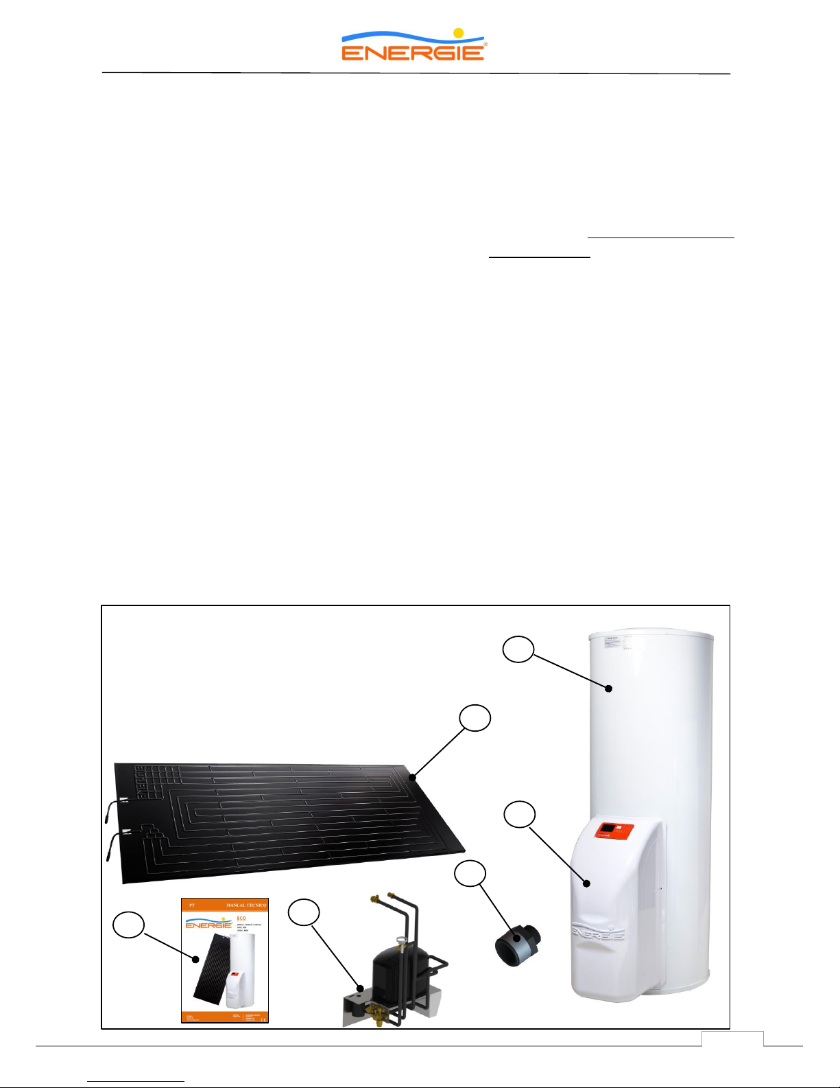
2.1. Contents
The equipment is supplied in three packages, one for the thermodynamic panel and its attachment
elements, one for the storage water heater and another for the thermodynamic block together with the
hood and elements to attach to the storage water heater.
The packages contain:
I. Thermodynamic panel + its attachment elements
II. Storage Water Heater
III. Thermodynamic block + attachment elements
IV. Hood + Electronic panel
V. Installation manual and Warranty
VI. Dielectric joints (except stainless steel tank)
II
I
V
III
IV
VI
Eco
7
Technical Manual
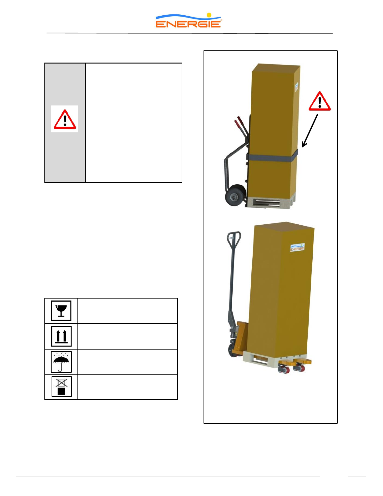
2.2. Transport
The equipment must be transported in its original
package to the place of installation. Check, before
beginning transport of the external unit, if the
path you will travel is unobstructed, in order to
prevent collisions that could cause damage to the
device.
The packages contain the following information
symbols:
WARNING
Transporting the equipment
must be carried out with an
inclination below 45º;
The equipment must be raised
and lowered with extreme
care to avoid impact that
could damage the material;
Make sure the belts and/or
transportation straps do not
damage the material;
Always use means of
transportation suitable for the
equipment (pallet lift, forklift,
etc…);
Fragile, handle with extreme
caution
Make sure the arrows are always
up
Keep the package dry
Do not stack packages

Eco
8
Technical Manual
3. SPECIFICATIONS
3.1. Running principle
The thermodynamic solar system Eco, is an
equipment based upon the principle of cooling by
compression – Principle of Carnot – which we
designate Thermodynamic Solar Systems: solar
panel and heat-pump. The solar panel, the main
component, placed outside, is in charge of
collecting the energy from:
Diffuse and direct solar radiation.
External air, by natural convection.
The wind effect (almost invariably
available).
Rainwater.
The temperature gradient caused by the external
agents mentioned, ensures the klea (ecological
cooling fluid) will evaporate inside the solar panel.
The absence of glass in the panel allows for an
increased thermal exchange by convection.
After circulation in the panel, the klea is aspirated
by the system’s mechanical component, the
compressor, which will increase its temperature
and pressure; it is then transferred to the water
circuit through a heat exchanger.
Before the Klea returns to the solar panel it is
necessary that there should be a narrowing, that
is, reduce the pressure and ensure that it is again
in a liquid state, thus completing the cycle.
The easy way we combine technology with a law
of Nature (change of state of a fluid),
demonstrates the true potential of the
Thermodynamic Solar System - Eco.
Eco
9
Technical Manual
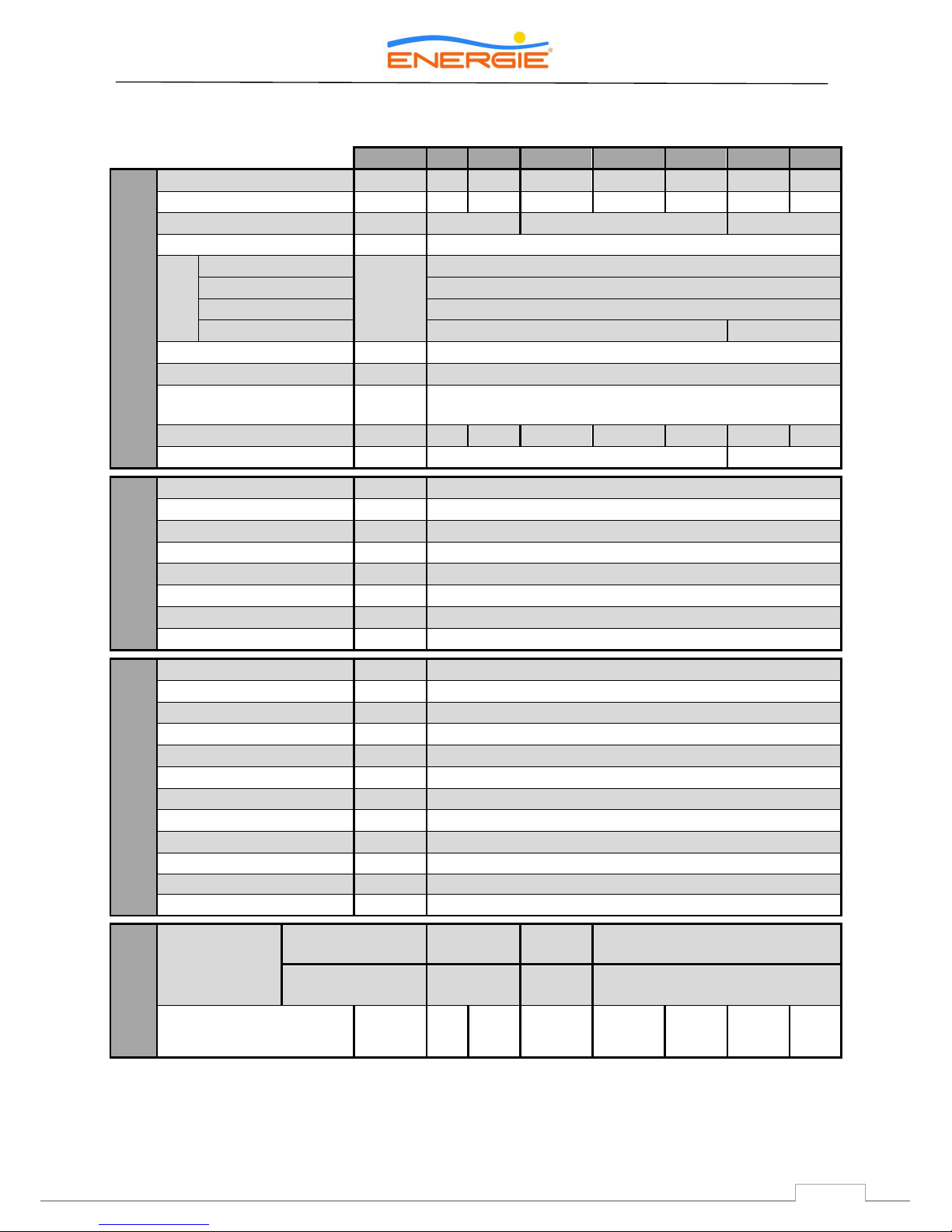
3.2. Technical features (x1 panel)
Unid
250i
300i
200esm
250esm
300esm
250ix
300ix
HOT WATER CYLINDER
Dry Weight
Kg
62
74
73
83
95
69
81
Capacity
lts
250
300
200
250
300
250
300
Internal Protection
-
Stain. Steel
Enamelled
Stain. Steel
Cathodic Protection
-
Magnesium Anode (1”1/4 Female)
Hydraulic
Joints
Water – Inlet and Outlet
inch
3/4” Male
TP Valve
1/2” Female
Recirculation
3/4” Male
Coil – Inlet and Outlet
Not Applicable
1” Male
Maximum Pressure
bar
7
Test Pressure
bar
10
Maximum Water
Temperature
°C
80
Heat Loss (EN 12897)
kWh/24h
1,01
1,17
1,04
1,2
1,39
1,01
1,17
Exchanger Output Power
1
kW
Not Applicable
a)30,0; b)18,0
THERMODYNAMIC
SOLAR PANEL
Material
-
Solokote Anodized Aluminium
Dimensions (L x W x H)
mm
2000 x 800 x 20
Weigh
kg
8
Max Working Pressure
bar
12
Test Pressure
bar
15
Max Exposure Pressure
°C
120
Min Running Temperature
°C
- 5
Min Exposure Temperature
°C
- 40
THERMODYNAMIC BLOCK
Width / Height / Depth
mm
320 / 710 / 280
Weight
kg
17,5
Absorved Power (Med/Max)
W
390 - 550
Thermal Power (Med/Max)
W
1690 / 2900
Electrical Backup Power
W
1500
Compressor Type
-
Hermetic
Compressor Noise Level
dB
39
Refrigerant / Qt.2
- / g
R134a / 11002
Piping Material - Copper (DHP ISO1337)
Line (Liq. | Asp.)
inch
1/4” | 3/8”
Power Supply
V / Hz
230 monophase / 50
Fuse (Main | Elect. Heater) A 10 | 10
Performance
Performance
Coeficient
(COP)
3
EN 255 – 3
(air 7 ºC / air 20 ºC)
3,4 / 4,6
3,3 / 4,5
3,4 / 4,6
EN 16147
(air 7 ºC)
2,9
2,8
2,9
Amount of Useful Water at
40 ºC
lts
317
369
242
321
374
308
360
1) a) Primary (Tin=90 ºC; Tout=80 ºC); Production DHW (Tin=10 ºC; Tout=60 ºC)
b) Primary (Tin=70 ºC; Tout=60 ºC); Production DHW (Tin=10 ºC; Tout=60 ºC)
2) The amount of fluid must be checked by the installer. In some cases it is necessary to add or remove fluid in order to ensure the
correct running of the system.
3) Water temperature from 10 ºC to 54 ºC
Eco
10
Technical Manual
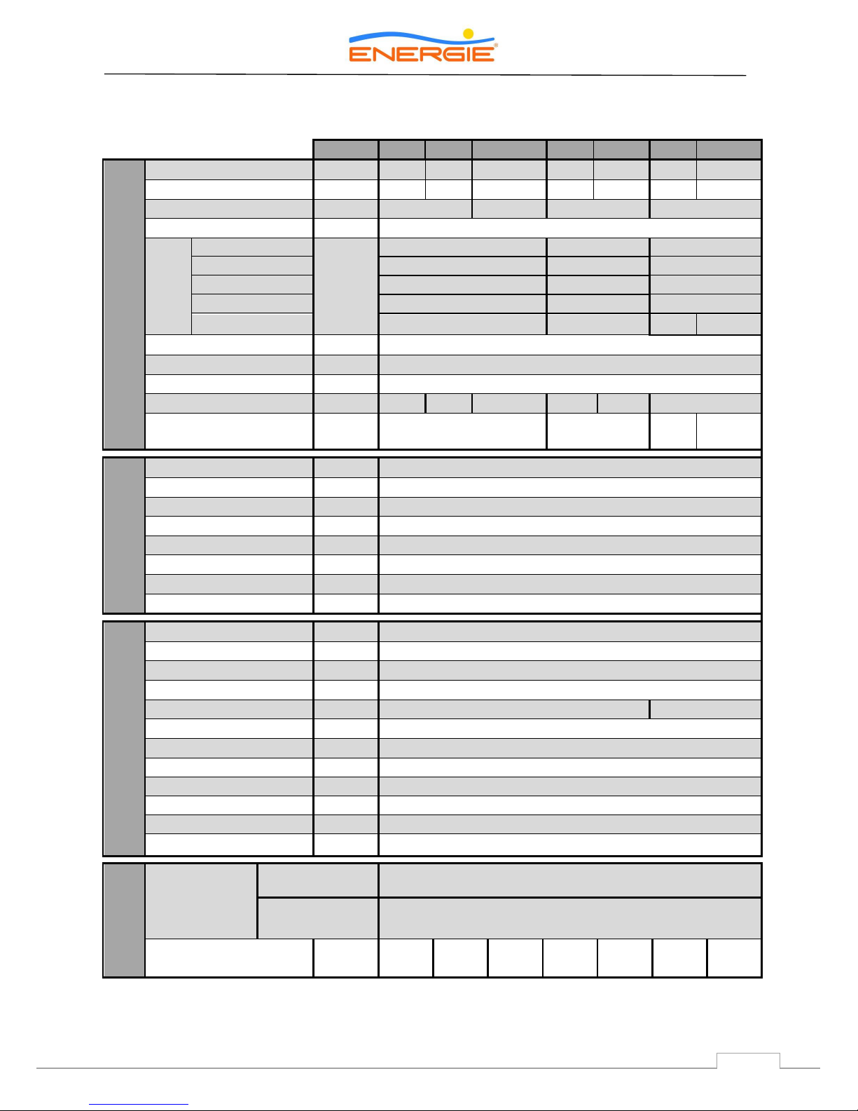
3.3. Technical features (2x panels)
Unid
250is
300is
300esms
250isx
300isx
450is
450isx
HOT WATER CYLINDER
Dry Weight
Kg
62
74
95
69
81
110
121
Capacity
lts
250
300
300
250
300
445
445
Internal Protection
-
Stain. Steel
Enamelled
Stain. Steel
Stain. Steel
Cathodic Protection
-
Magnesium Anode (1”1/4 Female)
Hydraulic
Joints
Inlet
inch
3/4” Male
3/4” Male
1” Male
Outlet
3/4” Male
3/4” Male
1” Male
TP Valve
1/2” Female
1/2” Female
1/2” Female
Recirculation
3/4” Male
3/4” Male
3/4” Male
Coil – Inlet and Outlet
Not Applicable
1” Male
N/A
1” Male
Maximum Pressure
bar
7
Test Pressure
bar
10
Maximum Temperature
°C
80
Heat Loss
(EN 12897)
kWh/24h
1,01
1,17
1,39
1,01
1,17
1,81
Exchanger Output Power1
kW
Not Applicable
a)30,0; b)18,0
N/A
a)54,2;
b)32,5
THERMODINAMIC
SOLAR PANEL
Material
-
Solokote Anodized Aluminium
Dimensions (L x W x H)
mm
2000 x 800 x 20
Weight
kg
8
Max. working pressure
bar
12
Test pressure
bar
15
Max. exposure temp.
°C
120
Min. running temperature
°C
- 5
Min. exposure temp.
°C
- 40
THERMODYNAMIC
BLOCK
Width / Height / Depth
mm
320 / 710 / 280
Weight
kg
20,5
Absorbed power (Med/Max)
W
595 / 890
Thermal power (Med/Max)
W
2800 / 4550
Electrical Backup Power
W
1500
2200
Compressor Type
-
Hermetic
Compressor Noise Level
dB
39
Refrigerant / Qt.2
- / g
R134a / 1300
2
Piping Material - Copper (DHP ISO1337)
Line (Liq. | Asp.)
inch
3/8” | 1/2”
Power Supply
V / Hz
230 Monophase / 50
Fuse (Main | Elect. Heater) A 10 | 10
Performance
Performance
Coeficient
(COP) 3
EN 255 – 3
(air 7 ºC / air 20 ºC)
3,5 / 4,7
EN 16147
(air 7 ºC)
3,0
Amount of Useful Water
at 40 ºC
lts
317
369
374
308
360
530
517
1) a) Primary (Tin=90 ºC; Tout=80 ºC); Production DHW (Tin=10 ºC; Tout=60 ºC)
b) Primary (Tin=70 ºC; Tout=60 ºC); Production DHW (Tin=10 ºC; Tout=60 ºC)
2) The amount of fluid must be checked by the installer. In some cases it is necessary to add or remove fluid in order to ensure the
correct running of the system.
3) Water temperature from 10 ºC to 54 ºC
Eco
11
Technical Manual
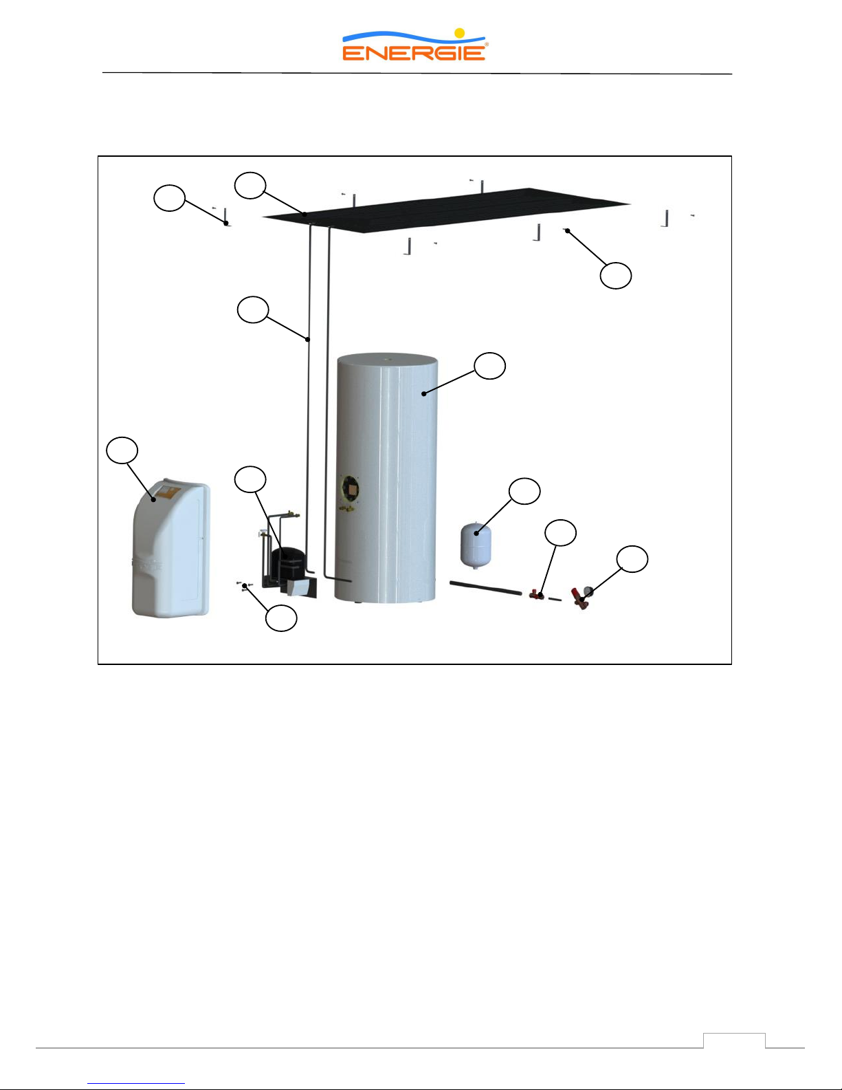
3.4. Main Components
3.4.1. General diagram of assembly
[1]
Thermodynamic Solar Panel
[2]
L-shaped fastenings for attachment of Aluminium Panel
[3]
Set of bolt, female, washer and bushing (6x or 8x)
[4]
Copper pipes
[5]
Water storage heater
[6]
Thermodynamic block
[7]
Hood + Display
[8]
Bolts CHC M8
[9]
Expansion tank
[10]
Safety device
[11]
Pressure reduction valve
3 1 2
5 4 9
10
8
11
7
6
Eco
12
Technical Manual
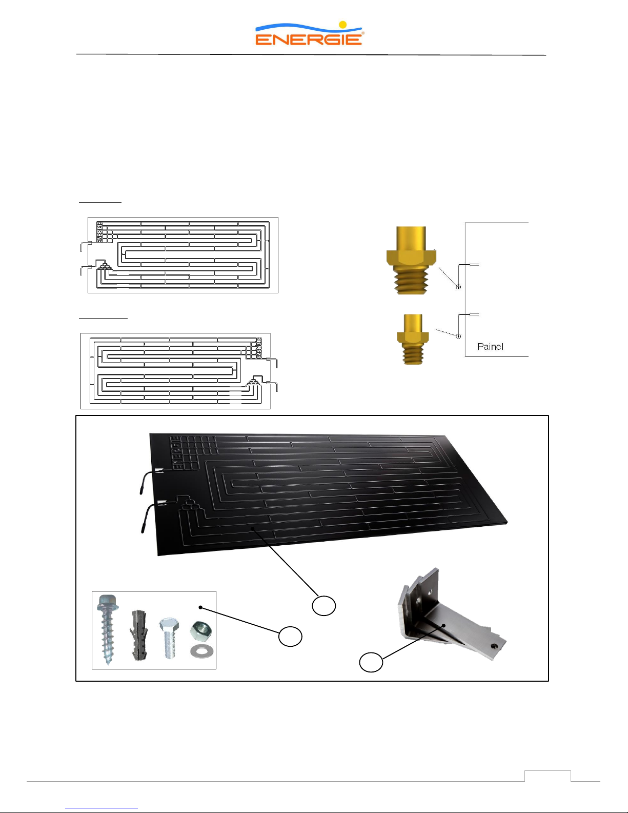
3.4.2. Thermodynamic Solar Panel
The solar panel is a roll-bond type plate
manufactured in double channel pressed
aluminium, with a post-press anodizationoxidation that creates a dark tone aspect. There
are two types of panels available: left and right
(designated according to side of connections).
Left Panel
Right Panel
The panel has a standard dimension of 2000 mm x
800 mm x 20 mm.
The panel connections are Flare SAE (threaded)
type. These connections are used only in the
equipments with one panel.
3/8’’ Aspiration (upper part)
1/4’’ Liquid (lower part)
[12]
Thermodynamic Solar Panel
[13]
Aluminium L-shaped fastenings for attachment of Thermodynamic Panel (6x or 12x)
[14]
Elements for attachment of Thermodynamic Panel
12
13
ODS (welded to panel)
3/8” flare Male SAE
ODS (welded to panel)
1/4” flare Male SAE
14
Eco
13
Technical Manual
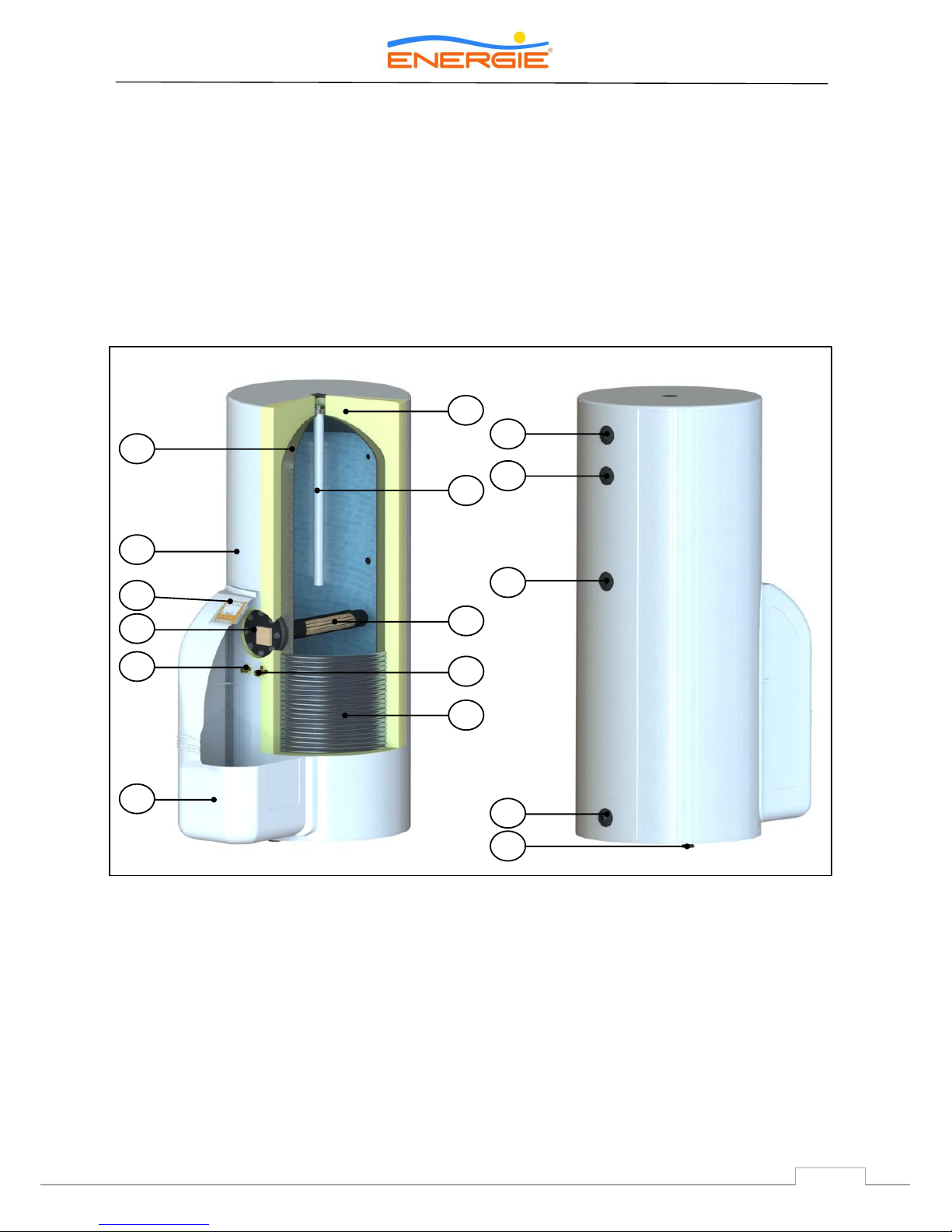
3.4.3. Storage Water Heater
The hot storage water heater is vertical and rests
on the floor. The tank is made of carbon steel with
enamel coating or in stainless steel. The thermal
insulation is of expanded polyurethane with a
thickness of 40 mm.
The storage water heater has a cold water inlet,
hot water outlet, AQS return and an outlet for the
expansion valve. It also comes equipped with a
magnesium anode in the upper section.
There is, in the central part of the storage water
heater, a flanged opening for placing the support
resistance, as well as safety thermostat and
temperature probe.
[14]
Hood of Eco
[25]
Adjustable support foot
[15]
Condenser / Coil
[26]
Cold water inlet
[16]
“One-Shot” Female Valve
[27]
Recirculation
[17]
“One-Shot” Male Valve
[28]
TPR Valve
[18]
Temperature Probe + Safety Thermostat
[29]
Hot water outlet
[19]
Resistance
[20]
Display
[21]
External Sheet
[22]
Magnesium Anode
[23]
Tank
[24]
Polyurethane Insulation
23
22
24
20
21
18
17
19
16
15
14
29
27
25
26
28
Eco
14
Technical Manual
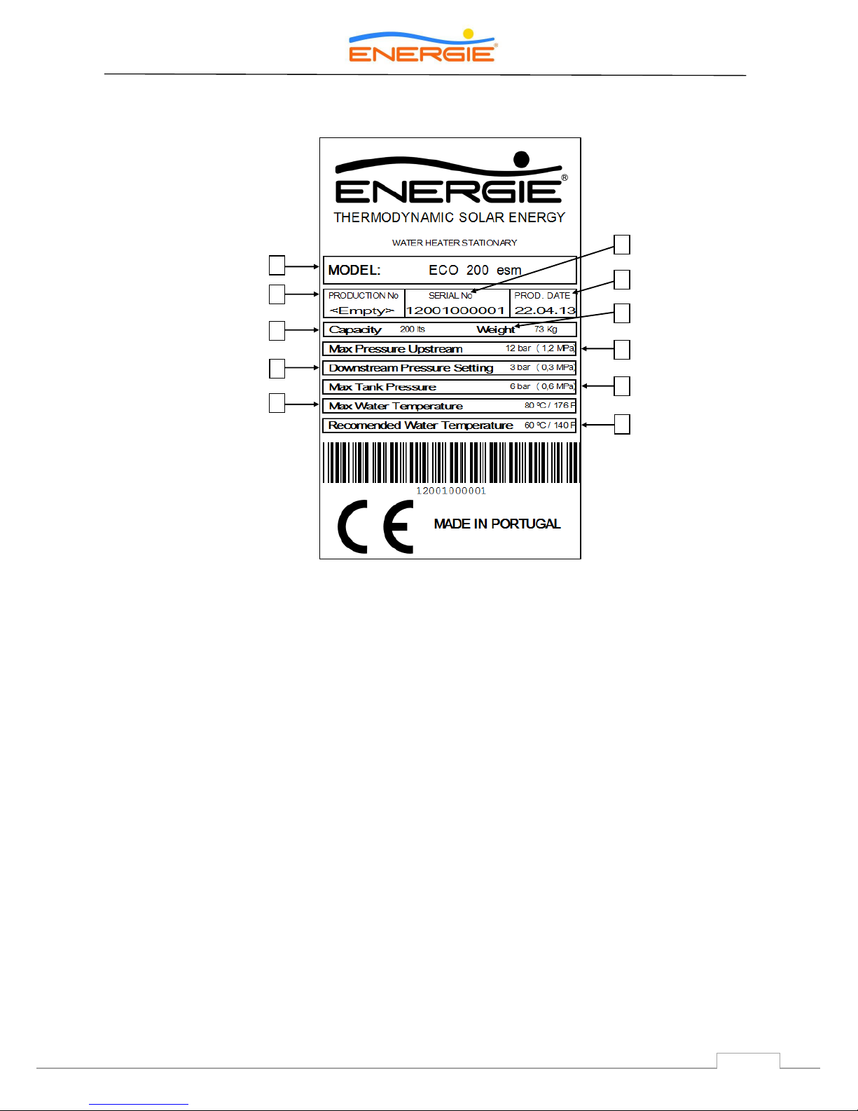
Seal with features
[A]
Model
[B]
Production number
[C]
Serial number
[D]
Production date
[E]
Volume
[F]
Weight
[G]
Downstream pressure of pressure throttle valve
[H]
Upstream Maximum Pressure of pressure throttle valve
[I]
Maximum pressure in Storage Water Heater
[J]
Maximum Temperature in Storage Water Heater
[L]
Recommended Temperature in Storage Water Heater
A
B E G
J
C
D
F H I
L
 Loading...