

www.energie.pt 1
Assembly and User Manual
Thermodynamic Solar System
Combi [6 | 12 | 16]
Combi 12 HT
Directives
2006/95/CE
Review: 1
Version: 0
Date: 06/01/2015
CENTRAL HEATING + DOMESTIC HOT WATER
EN

ASSEMBLY AND USER MANUAL
Combi [6 | 12 | 16] & Combi 12 HT
2 www.energie.pt
INDEX
1. Introduction .............................................................................................................................. 4
2. General .................................................................................................................................... 4
2.1. Symbology ............................................................................................................................. 4
2.2. Manufacturer’s Liability............................................................................................................ 4
2.3. Installer’s Liability ................................................................................................................... 4
2.4. Safety Information .................................................................................................................. 5
3. Indications ................................................................................................................................ 5
3.1. Unit inspection ........................................................................................................................ 5
3.2. Lodging a complaint ................................................................................................................ 5
3.3. Packaging .............................................................................................................................. 5
3.4. Transporting the unit ................................................................................................................ 6
3.5. Unit storage ........................................................................................................................... 6
4. Comby Sistem .......................................................................................................................... 6
4.1. Operation ............................................................................................................................... 6
4.2. Technical Specifications .......................................................................................................... 7
4.3. Components .......................................................................................................................... 8
4.3.1. Combi Block .............................................................................................................................. 8
4.3.2. Thermodynamic solar panels .................................................................................................... 9
5. Installation ................................................................................................................................ 9
5.1. Installation Tools required........................................................................................................ 9
5.2. Thermodynamic Solar Panel .................................................................................................... 9
5.2.1. Panel orientation ....................................................................................................................... 9
5.2.2. Inclination ................................................................................................................................ 10
5.2.3. Distance .................................................................................................................................. 10
5.2.4. Unevenness ............................................................................................................................ 11
5.2.5. Standard Gap of the Panels .................................................................................................... 11
5.2.6. Direction of the Panels ............................................................................................................ 12
5.2.7. Relative position of the panels ................................................................................................. 13
5.2.8. Fixation .................................................................................................................................... 14
5.2.9. Liquid Distributor and Collector, placement and connection .................................................... 14
5.3. Combi Block ......................................................................................................................... 16
5.3.1. Installation site ......................................................................................................................... 16
5.3.2. Connections at the Combi Block.............................................................................................. 17

ASSEMBLY AND USER MANUAL
Combi [6 | 12 | 16] & Combi 12 HT
www.energie.pt 3
5.3.3. Removing the covers ............................................................................................................... 18
5.3.4. Electrical connections .............................................................................................................. 19
5.3.5. Implementation of piping connections (Welds) ........................................................................ 20
5.3.6. Leak test .................................................................................................................................. 21
5.3.7. Vacuum ................................................................................................................................... 21
5.3.8. Refrigerant R-407C (except Combi 12 HT) ............................................................................. 22
5.3.9. Fluid Charge ............................................................................................................................ 22
5.4. Hydraulic Connections .......................................................................................................... 23
5.5. Temperature Probe ............................................................................................................... 25
6. Control Panel.......................................................................................................................... 25
7. Error Messages ...................................................................................................................... 27
8. Annexes A (Wiring Diagram) .................................................................................................... 28
8.1. Combi System 220-240 Vac / 1+N / 50 Hz .............................................................................. 28
8.2. Combi System 400-420 Vac / 3+N / 50 Hz .............................................................................. 29
8.3. Glossary .............................................................................................................................. 30
9. Annexes B - Installation ........................................................................................................... 31
9.1. Plan ................................................................................................................................................. 31
9.2. Glossary .......................................................................................................................................... 32
10. Warranty ................................................................................................................................ 33
Revisão 1
ASSEMBLY AND USER MANUAL
Combi [6 | 12 | 16] & Combi 12 HT
4 www.energie.pt
1. INTRODUCTION
Esteemed Client,
Thank you and congratulations for buying an ENERGIE product, the upshot of several years of experience in the
sector.
We have built products based on specific studies, top quality materials and highly advanced technologies.
Our company’s serious approach ensures you all the support you’ll need from the sizing stage, to installation and
assistance.
For the best use of this product we would ask you to read this instructions manual carefully in which you will find all
the indications, information and tips you need to enjoy all the advantages that this appliance has to offer and by
following its indications and regulations in force you will be assured of optimum operation and a perfect performance.
The information contained in this document is subject to any modifications deemed necessary to enhance the
product without any prior notice.
2. GENERAL
2.1. Symbology
The notes/symbols shown can be found throughout the manual. They are intended to indicate and draw attention
to certain situations/indications. In this way we seek to ensure any possible problems for the installer or user and
assure smooth equipment performance.
Warning / Important Information.
Indicates any potentially dangerous situation which may result in physical injury or material damage.
2.2. Manufacturer’s Liability
Our products are manufactured in line with the requirements of the various European directives.
With a constant concern for the quality and performance of our products, we make a continuous effort to improve
them. This is why we reserve the right to modify the information described in this document at any time.
As the manufacturers we cease to be liable for the malfunctioning or even breakdown of the equipment whenever:
✓ The usage instructions are not respected.
✓ The installation instructions are not respected.
✓ Lack of maintenance (where required).
2.3. Installer’s Liability
The installer is liable for proper equipment installation and for putting into operation.
The installer must bear in mind the following notes:
✓ Read and closely follow the instructions of the manuals supplied with the appliance.
✓ Carry out installation in accordance with standards in force and required by the manufacturer.
✓ Carry out the initial start-up of the equipment and verify all the checkpoints.

ASSEMBLY AND USER MANUAL
Combi [6 | 12 | 16] & Combi 12 HT
www.energie.pt 5
✓ Explain the installation to the user as well as how he/she should use the equipment.
✓ Notify the user of its obligation, where required, as regards equipment maintenance and inspection
operations.
✓ Obligation to provide the user with all the documentation supplied with the equipment (manuals and
warranty certificate).
2.4. Safety Information
With a view to protecting the physical integrity of the operator as well as of the equipment, it is vital that all the safety
information noted in this manual should be taken into account.
This appliance is not envisaged for use by people (including children) whose physical, sensorial or mental
capabilities are reduced or by people without any experience or knowledge, unless they have been given
supervision or instructions about use of the appliance by someone responsible for its safety.
Children must be supervised to ensure that they do not play with the appliance.
3. INDICATIONS
This manual accompanies all the “Combi Systems” and contains important instructions which must be followed
during installation.
3.1. Unit inspection
The unit was tested and inspected for quality assurance before its dispatch. Carefully inspect the equipment
components (Combi, Solar Panels etc.) as soon as you receive it in order to check that all the equipment is intact.
Confirm whether all the parts requested have been received in accordance with that which has been specified and
whether the type, size and voltage of the unit are correct.
3.2. Lodging a complaint
If damage is identified in the inspection carried out at the time of reception of the unit, describe the damage in the
transport reception document. Any transport complaint must be submitted at the act of delivery.
If you are in any doubt, get in touch with ENERGIE to obtain information about how to lodge a complaint with the
haulage company.
Should damage occur during transport, do not install the unit. Keep all packaging for inspection of the
hauler.
3.3. Packaging
The Combi System is packed in a bottomless cardboard box and is secured to a treated pinewood pallet using
plastic tape.
The thermodynamic solar panels are packed in cardboard boxes unless otherwise provided for.
The dimensions of the boxes, pallets and respective weights for the Combi System are shown in table below.
ASSEMBLY AND USER MANUAL
Combi [6 | 12 | 16] & Combi 12 HT
6 www.energie.pt
Model
Box (H*L*P mm)
Pallet (H*L*P mm)
Weight (Kg)
Combi 6
2020x750x1000
140x750x1000
215
Combi 12
227
Combi 16
232
Combi HT 12
232
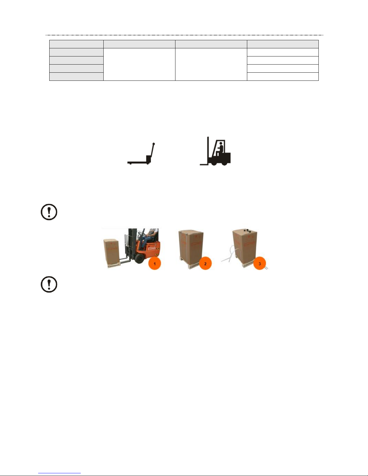
3.4. Transporting the unit
The tools recommended for transporting the unit whilst it is still in the pallet may be: forklift truck or pallet rack.
Where possible, the latter must move/transport the unit to the final destination (point of installation).
pallets truck lift truck
When transporting the unit, make sure that you only lift it by its lower part and always with the unit placed on the
pallet. Do not try to move the unit without help.
Transportation and handling must always be done on vertical.
It is vital to follow all the warnings and recommendations stated on the packaging boxes.
3.5. Unit storage
If the unit is not installed immediately, keep it in a safe place protected from the weather in such a way that it does
not suffer any kind of damage which may hinder its correct operation. Poor installation of the unit may give rise to
the cancellation of the manufacturer’s warranty.
4. COMBY SISTEM
4.1. Operation
Combi Systems are items of equipment intended for heating and domestic hot water.
The thermodynamic panel is placed on the exterior and it ensures the capturing of energy as regards:
✓ Direct and diffuse radiation
✓ Outside air by natural convection.
✓ Wind effect (almost always to be found).
✓ Rainwater

ASSEMBLY AND USER MANUAL
Combi [6 | 12 | 16] & Combi 12 HT
www.energie.pt 7
The temperature difference brought about by the previous factors ensures that the fluid will change to vapour state
inside the panel.
The compressor aspirates the refrigerant fluid (vapour) of the panel, raising the pressure and temperature thereof,
which is transmitted to the water circuit by way of a heat exchanger.
The Exchanger is located inside the cabinet (Combi Block), providing heat to the water which is inside.
When the refrigerant fluid reaches the expansion valve it is at its liquid phase and the load loss owing to
strangulation reduces the pressure and the fluid is re-prepared for entry into the panels.
4.2. Technical Specifications
The ENERGIE Combi Systems are presented on the market in a range of 4 models in accordance with the table
below:
Un.
Combi 6
Combi 12
Combi 16
Combi 12HT
Thermodynamic
Solar Panels
Quantity 6
12
16
12
Weight
kg
48
96
128
96
Exposed Capture Surface
m²
9,6
19,2
26,6
19,2
Refrigerant
Type R 407C
R 407C
R 407C
R 134a
Amount (pre charge)
kg
1,6
2
2,5
2
Test Pressure
bar
30
LP Switch Open Value
bar 1 0,3
LP Switch Close Value
bar 2 1,7
HP Switch Open Value
bar
28
21
HP Switch Close Value
bar
23
16,0
Electrical Data
Single Phase / Three Phase
1P+N
3P+N
1P+N
3P+N
1P+N
3P+N
Power Supply
220-240V~
50Hz
380-420V~
50Hz
220-240V~
50Hz
380-420V~
50Hz
220-240V~
50Hz
380-420V~
50Hz
Rated Power Consumption*
kw
1,2 - 2,2
1,9 - 3,1
3,2 - 5,2
1,7 - 3,0
Auxiliary Heater 1
kw
4,5
4,5
6
6
Auxiliary Heater 2 (DHW)
kw
1,5
1,5
1,5
1,5
Output Capacity
kw
4,9 - 9,7
9,2 - 16,7
14,2 - 24,2
7,8 - 15,8
Domestic Hot Water
Material
Stainless Steel
Capacity
l
200
Safety Thermostat Activ.
°C
80
Cathodic Protection
Magnesium Anode
Maximum Running
Pressure
bar
7
Maximum Running
Temperature
°C
80 (safety thermostat)
Expansion Vessel
l 5 Inlet / Outlet Connections
inch
3/4"
Heating
Heating Pipe Diameter
mm
28
Pressure Safety Valve
bar 7 Expansion Vessel
l
10 (installations<120l)
Nominal Flow
m³/h
0,7
1,1
1,5
1
*Rated Power Consumption Without Auxiliary Heater 1 and 2
ASSEMBLY AND USER MANUAL
Combi [6 | 12 | 16] & Combi 12 HT
8 www.energie.pt
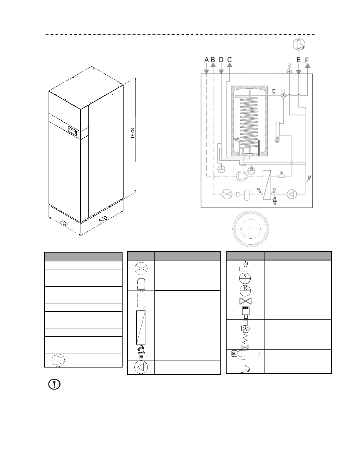
4.3. Components
4.3.1. Combi Block
IMPORTANT
* The Combi Block has one 10 l expansion vessel sized for heating line with ≤ 120 l (7 bar safety valve and
pre-charge circuit of 1,5bar). If the heating installation has more than 120 l, a new expansion vessel
should be sized.
** It’s mandatory to install the filter (supplied with the system) on the heating line.
*** It’s mandatory to install the safety valve (supplied with the system) on the heating line.
Symbol
Meaning
[A]
Aspiration Line
[B]
Liquid Line
[C]
DHW Outlet
[D]
DHW Inlet
[E]
Heating Inlet
[F]
Heating Outlet
[G]
Tank electric
heater
[H]
Coil Outlet
[I]
Coil Inlet
[J]
Mg anode
Compressor
Symbol
Meaning
Thermostatic
expansion valve
Dry filter
Liquid receiver
Plate heat exchanger
Drain valve
Circulator pump
Symbol
Meaning
Flow switch
Expansion vessel 5 l
Expansion vessel 10 l*
Cut-off valve
Air vent
Three way valve
Safety valve ***
Line electric heater
“y” filter**
G D C
G
Cut of upper
view from tank
J
H
S4
J
I

ASSEMBLY AND USER MANUAL
Combi [6 | 12 | 16] & Combi 12 HT
www.energie.pt 9
4.3.2. Thermodynamic solar panels
The solar panel is a plate made of twin-channel pressed aluminium with post-pressing anodic oxidation. The panel
has the dimensions 2000 mm x 800 mm x 5 mm and it has a fluid flow entry and exit in a copper-aluminium pipe
with an interior diameter of ¼’’
5. INSTALLATION
5.1. Installation Tools required
To ensure correct assembly of the equipment, the installing technician must be endowed with the following tools:
✓ Manometers (low and high pressure).
✓ Vacuum Pump.
✓ Refrigerant gas loading station or scales.
✓ Pipe cutter.
✓ Adjustable spanner.
✓ Screwdriver.
✓ Measuring tape.
✓ Tube bender.
✓ Tube expander.
✓ Refrigerant gas cylinder.
✓ Rotoblock wrench.
✓ Set of hydrant keys or ratchet.
✓ Blowpipe (welding).
✓ Copper rods with 40% of Silver.
✓ Descaler.
To verify the operationality of the equipment the installing technician must have at its disposal:
✓ Multimeter.
✓ Appliance for measuring temperature.
5.2. Thermodynamic Solar Panel
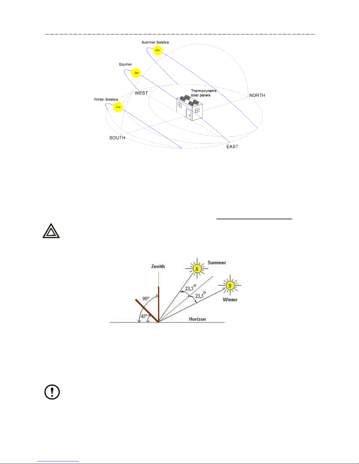
5.2.1. Panel orientation
The panels must be at ventilated places and preferably not be exposed to any kind of shade.
ENERGIE panels must preferably be oriented in a southerly direction (at north hemisphere), but they may also
have an orientation towards Northeast and Northwest.
ASSEMBLY AND USER MANUAL
Combi [6 | 12 | 16] & Combi 12 HT
10 www.energie.pt
5.2.2. Inclination
The inclination angle of the sun rays with regard to the horizontal varies in accordance with the seasons of the year.
In Winter, at the Zenith, the solar rays form an angle of 20º to 40º with regard to the horizon. In Summer the angle
is between 60º and 80º.
To get the most out of the solar rays on the panel, it’s best to choose an inclination between 45º and 90º.
The panels inclination should never be less then 10°.
However, you may install the panels with another inclination in certain situations.
5.2.3. Distance
The maximum distance between the panels and the Combi Block depends on certain factors such as the
equipment model, the no. of curves, the piping diameter etc.
However, we would recommend that the distance should not exceed the 20m.
For Installations with a distance greater than those indicated must contact the Technical Dept.
ASSEMBLY AND USER MANUAL
Combi [6 | 12 | 16] & Combi 12 HT
www.energie.pt 11
5.2.4. Unevenness
Under normal circumstances the total maximum gradient must always be less than 15 mts. However, there are
situations where it is not possible to respect these distances, in these cases you must consult our technical
department.
The aspiration piping must rise above the level of the panels, in the same way as the distribution shaft in order to
avoid the rapid siphon effect of the liquid at the time of the stoppage of the compressor.
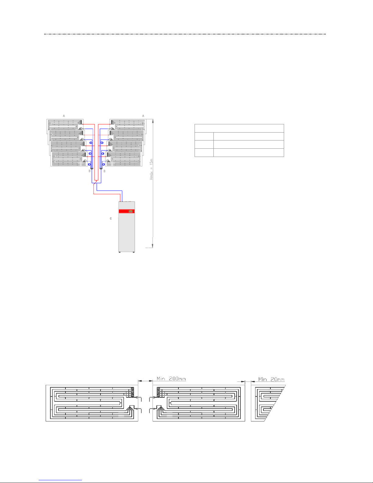
5.2.5. Standard Gap of the Panels
The position of the panels and the choice of the sides of the connections must be carried out so as to limit the length
of the piping and simplify the connections.
The panel gap is determined so as to facilitate its placement and the implementation of the connections between
piping, though due consideration must be given to:
✓ Minimum space between the panels on the connections’ side: 200mm (ideal space: 500mm).
✓ Space between the panels on the side opposite the connections: they should preferably not be
completely stuck together (preferably> 20mm)
Key:
A
Solar Panels
B
Distributor
C
Combi Block

ASSEMBLY AND USER MANUAL
Combi [6 | 12 | 16] & Combi 12 HT
12 www.energie.pt
5.2.6. Direction of the Panels
The direction of the panels is defined by the outlets of the tubes pointing downwards and by the view of the front
part of the panel. They must always be placed with the largest length horizontally and the connections pointing
downwards. In this context two panel models are manufactured:
- Left-hand panel
A – Liquid Line (Inlet)
B – Vapour Line (Outlet)
Left: A left-hand panel is installed on the right (front view). To this end, it has connections on the left side.
The Solar panel must not be installed on the vertical in accordance with the representation indicated
above with a red cross.
- Right-hand Panel
A - Liquid Line (Inlet)
B - Vapour Line (Outlet)
Right: A right-hand panel is installed on the left-hand side (front view). To this end, it has connections on righthand side.
The Solar panel must not be installed on the vertical in accordance with the representation indicated
above with a red cross.

ASSEMBLY AND USER MANUAL
Combi [6 | 12 | 16] & Combi 12 HT
www.energie.pt 13
5.2.7. Relative position of the panels
The relative Position of the panels depends on the system to be installed, the availability of the installation area, the
architectonic integration etc.
In the diagrams below some of the possible positioning layouts of the panels are represented. However, you may
consult in the annex complementary information about the position of the panels in the installation.
Combi 6
Combi 12
In the event of some other positioning of the panels, you must contact our Technical Department.

ASSEMBLY AND USER MANUAL
Combi [6 | 12 | 16] & Combi 12 HT
14 www.energie.pt
5.2.8. Fixation
The affixation of panels depends on the installation site and the method and type of affixation is the installer’s
decision. However, you must bear various factors in mind (described above such as, for example, distance,
orientation…).
For a correct affixation of the panels, as regards the physical part of the affixation supports they must have a sturdy
structure in line with the circumstances of the site. Each panel must be secured at 6 points (as a minimum).
The image below illustrates an example of the affixation used:
The affixation of the panels is ensured by aluminium supports*. The support is bent in “L” form with two M8 through
holes. The support base is secured to the roof (where applicable) using an M6 screw and a plastic plug or a female
thread (depending on the situation).
The other support rib is secured to the panel by way of galvanised M6 screws to prevent corrosion situations.
* The aluminium supports are not supplied with this product.
The Panels must have a minimum gap of 50cm (from the previous and/or subsequent panel)
5.2.9. Liquid Distributor and Collector, placement and connection
To ensure that the fluid reach the panels in homogeneous fashion, a liquid distributor must be installed. This
same distributor includes as many distribution tubes as there are panels in the installation.
The distributor is placed between the panels. The connection tubes to the panels must have strictly the same length
and their ends connect directly to the panels.
The distributor and the collector may be placed before the installation of the panels for the sake of convenience
(obstruction, passage of distribution tubes behind the panels).
Only remove the pipe protection cover at the time of connection to the power and aspiration shafts with a view to
avoiding the penetration of impurities.
Install the distributor (s) vertically, face downwards (never horizontally!), thereby ensuring that the fluid reaches
the panels in homogeneous fashion.

ASSEMBLY AND USER MANUAL
Combi [6 | 12 | 16] & Combi 12 HT
www.energie.pt 15
If a shaft is too long for the length required, it must be rolled up and never cut.
If it is wished to shorten or elongate, this operation must be carried out on all the shafts with the same diameter.
All ø ¼” shafts must be welded to the lower connections of the panels (liquid inlet). The shafts of the main distributor
must be welded to the secondary distributors.
✓ A – Main Liquid Line
✓ B – Main Liquid Line viewed from above.
It is vital that the power shafts (Ø 1/4’’) should have the same length and the same is true of the main
distributor shafts.
Depending on the Thermodynamic Block model and the position of the panels, one or more aspiration collectors
must be carried out.
The aspiration which allows the collection of the refrigerant fluid in its gaseous state must regroup all the panel
aspiration outlets (∅ 3/8’’) as far as the collector. This is shown in the figure below.
✓ B – Main Aspiration Line.
All the shafts must be welded to the upper panel outlets.
It is important for the connections at the collectors to be as simple as possible, respecting the instructions in the
event of any unevenness.
It is essential for the copper tubes used to be refrigerant type CUDHP according to the ISO1337 and/or according
to EN12735, both on the aspiration line and on the liquid line (power).
It is also recommended for all the piping to have good quality thermal insulation in order to avoid any possible
condensation.
The piping diameters vary with the system model as can be seen in the table below.
Model
Aspiration Line
Liquid Line
Combi 6
3/4’’
1/2’’
Combi 12
7/8’’
1/2’’
Combi 16
7/8’’
3/4’’
Combi 12 HT
7/8’’
1/2’’

ASSEMBLY AND USER MANUAL
Combi [6 | 12 | 16] & Combi 12 HT
16 www.energie.pt
5.3. Combi Block
5.3.1. Installation site
The choice of site where the Combi Block is placed is very important and must be carried out bearing mind a
certain number of criteria such as:
✓ Easy access and sufficient space to move the equipment as far as the installation site
✓ Load capacity of the ground (check the weight of the equipment)
✓ Equipment placed on a even base
✓ Point for hydraulic and electrical connections
✓ Avoid the possibility of vibration transmission
✓ Place anti-vibration supports between the appliance and the ground
✓ Position of the piping from the panels
✓ Protected from bad weather such as garages, cellars, attics etc
✓ Allow any possible assistance intervention
To install the Combi Block, is recommended that the site of installation allow the distances shown on the next
scheme:
The installation of the Combi Block near bedrooms should be avoided owing to the possible
transmission of vibrations and noise.
If the Combi Block is placed in the attic special care must be taken as regards the vibrations produced
under the wooden construction. Also provide for the placement of a tray under the appliance in
accordance with legislation to collect any water in the event of an installation rupture.
Never grab nor handle the Combi Block by the refrigerant or hydraulic connections.
300 mm
300 mm
300 mm
600 mm
150 mm

ASSEMBLY AND USER MANUAL
Combi [6 | 12 | 16] & Combi 12 HT
www.energie.pt 17
5.3.2. Connections at the Combi Block
The back of the Combi Block has the various connections in accordance with the designation set out below.
The Combi Block connections to the panels are supplied with two hermetic valves valves to avoid the penetration
of impurities and humidity in the refrigerant circuit wich are already installed according the picture bellow.
Key:
1
Inlet from panels
2
Outlet to panels
3
DHW Inlet
4
DHW Outlet
5
Heating inlet (to the block)
6
Heating outlet (from the block)
7
Electrical Connections
2
3
5 4 6 7 1
Location of two
hermetic valves

ASSEMBLY AND USER MANUAL
Combi [6 | 12 | 16] & Combi 12 HT
18 www.energie.pt
5.3.3. Removing the covers
1. Unscrew M6 screws on the top of the unit;
2. Move up and pull the front panel;
3. Unscrew M6 screws on the lateral as promenor X as picture bellow;
4. Pull the lateral panel.

ASSEMBLY AND USER MANUAL
Combi [6 | 12 | 16] & Combi 12 HT
www.energie.pt 19
5.3.4. Electrical connections
After the placement of the Combi Block it’s is necessary to connect the power supply cable and the two
thermostats (ambiente and external) to the elctric box of the Combi Block.
The power supply cable and the two thermostats should pass on the three electric gland placed on the back of the
Combi Block.
The power supply cable, the ambiente thermostat (TA) and the external thermostat (TEXT), should enter in the
bottom of electric switchboard.
Ambient
Thermostat
External
Thermostat
Electric Gland

ASSEMBLY AND USER MANUAL
Combi [6 | 12 | 16] & Combi 12 HT
20 www.energie.pt
5.3.5. Implementation of piping connections (Welds)
Once the Panels are installed and the Combi Block has been finally placed at the site, now the following types of
piping must be placed:
✓ Liquid (Outward to panels).
✓ Aspiration (Return from panels).
Before making the aforementioned connections, it is best to carry out the connections of the panel tubes to the:
✓ Liquid distributor (s).
✓ Aspiration collector (s)
The implementation of the connections is one of the most delicate points of the whole installation and it is extremely
important that the welds are carried out in line with all the basic criteria of a quality welding process.
The recommended welding type for implementing the piping connection is oxy-acetylene welding
(oxygen/acetylene). Other types of gas may also be used such as propane, for example.
The most delicate welds and which require the greatest care are carried out at the panels. It is necessary to place
a damp fabric strip which must envelop the “Thermoretractable Joint” so that it is fuly protected from high
temperatures caused by the blowlamp flame as shown in the figure below.
The copper is heated until it goes dark red at which point welding must begin. Bring the slightly inclined welding rod
closer without exposing it to the flame. As a general rule, the quantity to be applied is the same as one and a half
times the tube diameter. As soon as the alloy expands, stop heating and let it cool.
As soon as the weld is in a solid state, you must cool the whole area around the weld immediately with a damp
cloth.
Welds alongside the Combi Block must also be carried out with due care so as not to burn any component of the
Combi Block.
You should weld the aspiration and the liquid pipe to the corresponding pipping, at the back of the Combi Block. Be
carefull with the welding process.
Key:
A
Thermoretractable Joint
B
Connection and Weld
C
Aspiration Line (panel outlet)
D
Liquid Line (panel inlet)

ASSEMBLY AND USER MANUAL
Combi [6 | 12 | 16] & Combi 12 HT
www.energie.pt 21
After completing all the operations, the system is ready for submission to the leak test and the whole refrigerant
fluid loading process.
5.3.6. Leak test
A nitrogen load at a pressure of 10 bar (Max) would be ideal to ensure that there are no leaks on the welds carried
out. Once the installation is loaded, cover all the welds in soapy water and check that there are no nitrogen leaks.
The panels must remain 2 to 3 days with the nitrogen load so as to ensure that there is no leak. Once this operation
has been completed, remove all the nitrogen from the installation.
5.3.7. Vacuum
This operation is carried out using one load pipe, that is located inside of the unit, at the aspiration pipe. During this
operation, the two hermetic valves should be closed as factory instalation.
Before loading the refrigerant fluid, it is vital to carry out a vacuum at the installation. The purpose of the vacuum is
to remove all the air and humidity to be found on the circuit. The vacuum time depends on the following factors:
✓ Volume in m
3
/h of the vacuum pump.
✓ Volume of the system piping.
On average, the minimum vacuum time to be carried out at an installation, depending on the system installed, is
shown in the table below.
Combi
6
12 / 12 HT
16
Minimum vacuum time (hours)
3 6 7
Liquid Pipe
Load Pipe
Aspiration Pipe
Aspiration Hermetic
Valve
Liquid Hermetic
Valve

ASSEMBLY AND USER MANUAL
Combi [6 | 12 | 16] & Combi 12 HT
22 www.energie.pt
Once the vacuum process has been completed, the taps of the vacuum pump are closed. The vacuum manometer
must always have the same display after stopping the pump, thereby ensuring that the installation maintains the
vacuum is ready start.
5.3.8. Refrigerant R-407C (except Combi 12 HT)
The R-407C is a zeotropic mix (fluid comprising more than one component) made up of R32 (23%), R125 (25%)
and R134a (52%). It is chemically stable, is endowed with good thermodynamic properties and is a refrigerant with
a low environmental impact and very low toxicity.
As it is a zeotropic fluid, it is necessary to take care as regards the loading of the installation. If we load an installation
with a zeotropic refrigerant in vapour state, we run the risk that one of the components of the fluid will vaporize
before the others and hence the installation will have a greater proportion of this component.
This is why the installation must be loaded with the refrigerant in liquid state. The majority of R407c recipients have
a siphon, though it is worth checking. To load in liquid form you must proceed in the manner shown in the figure
below.
5.3.9. Fluid Charge
The amount of fluid in each system essentially depends on two factors, the type of Combi System and the distance
between the Combi Block and the panels. So each system as the following pre-charge:
Combi
6
12 / 12 HT
16
Minimum load (kg)
1,6
2,0
2,5
The two hermetic valves (liquid and aspiration) are closed, so, before charging the system is necessary to open
the valves. The direction to open the valves is showned in the picture below.
Refrigerant Gas Loading from
Canister with Siphon
Refrigerant Gas Loading from
Canister without a Siphon
CLOSE
OPEN

ASSEMBLY AND USER MANUAL
Combi [6 | 12 | 16] & Combi 12 HT
www.energie.pt 23
When the pressure is equalised at the manometers, the system is ready for compressor start up.
The fine-tuning (remaining load) of the system must be carried out via the “LOW” aspiration pipe very slowly (with
the compressor in operation). To this end the loading must be carried out slowly by the Aspiration Line until we
attain a difference of 20 ºC between the atmospheric Temperature and the aspiration Temperature (for low pressure
manometers with readings in VAPOUR!!).
Or there should be as close an approximation as possible to the following aspiration pressure values for the
respective exterior temperature (atmospheric temp. at the panels). This values are estimated for water return
temperatures of between 25 – 30ºC
Exterior
Temperature
Aspiration
Pressure
(ºC)
(bar) 0 1,2 5 1,6
10
2,2
15
2,9
20
3,6
25
4,5
30
5,5
You may not achieve exactly the desired pressure as this depends on some factors such as:
✓ Direct solar radiation on the panels;
✓ Ventilation;
✓ Relative humidity of the air;
✓ Variation in distances and unevenness of the installation piping;
5.4. Hydraulic Connections
The installation of the hydraulic system must be carried out by a competent professional, always
respecting the indications supplied by ENERGIE.
The Combi Block is fitted with a water circulator pump, according with the following graphic:
This circulator pump is sized to ensure the following flow rate at the condenser:
Exterior
Temperature
Aspiration
Pressure
(ºC)
(bar) 0 0,4 5 0,6
10
1,0
15
1,4
20
1,9
25
2,4
30
2,9
Combi 6 | 12 | 16
Combi 12 HT

ASSEMBLY AND USER MANUAL
Combi [6 | 12 | 16] & Combi 12 HT
24 www.energie.pt
Upon the initial installation and before establishing any hydraulic connection of the heating circuit to the Combi
Block, the whole hydraulic installation must be cleaned to remove any dirtiness, remains of material and similar
impurities.
After carrying out the cleaning of the circuit, connect it to the Combi Block, placing, without fail, a filter at the return
water inlet as an accumulation of residues in the condenser may bring about a system malfunction. The figure below
illustrates the type of filter that is supplied.
When installing the Combi Block along with another heating device we must bear in mind and place the
Combi Block in parallel with the existing equipment.
Firstly, preferably choose heat emitters with a large exchange surface (radiant flooring, radiators,
convectors, ventilo-convectors) as they allow distribution at a low temperature and better performances
to be obtained.
It is compulsory to apply an anticorrosive additive (stabilising liquid) on the hydraulic circuit to prevent
clogging, electrolysis phenomena and noise on the circuit.
When the circuit is properly connected, fill the hydraulic circuit (open the “cut-off” valve on the botton part of the
unit, number 1 on image below) and as this operation is being undertaken, you must purge (on the manual vent,
number 2) all the circuits, ensuring that you eliminate all the air pockets from the installation.
As a precaution, you must carry out a leak test. The test must be carried out with pressure 1.5 times the working
pressure.
Combi
6
12 / 12 HT
16
Minimum flow at the condenser (m3/h)
0,7
1,0
1,5
1
2

ASSEMBLY AND USER MANUAL
Combi [6 | 12 | 16] & Combi 12 HT
www.energie.pt 25
5.5. Temperature Probe
The temperature probes installed in the controller of the Combi System are NTC type (10KΩ ≈25ºC).
The installation of another temperature probe type will compromise the equipment operation, because the
temperature values read by the controller will not be true.
6. CONTROL PANEL
The electronic panel of the Energie Combi System takes the form of a console whereby several operating settings
can be configured such as:
✓ Water outward and return temperature.
✓ Temperature differentials.
✓ Timers
✓ Typical ground plans of installations.
✓ Etc. (consult attached Electronic device manual)
The electronic panel has the following configuration as the background image of the display and it is possible to
view different settings simultaneously:
0
5
10
15
20
25
30
35
0,0
1,8
3,6
5,4
7,2
9,0
10,8
12,6
14,4
16,4
18,2
20,0
21,8
23,8
25,6
27,4
30,5
33,4
36,3
39,1
42,0
44,9
47,8
50,7
53,6
56,5
59,4
Resistance
(KΩ)
Temperature (°C)

ASSEMBLY AND USER MANUAL
Combi [6 | 12 | 16] & Combi 12 HT
26 www.energie.pt
For more information about the electronic panel, please read the “Energie Electronic Panel” manual that is
supplied with the equipment.
ERROR Code
System Status
Date and Time
CRONO
Temp. probes
Leds

ASSEMBLY AND USER MANUAL
Combi [6 | 12 | 16] & Combi 12 HT
www.energie.pt 27
7. ERROR MESSAGES
Before seeking Technical assistance, follow the steps of this table to check whether it is needed.
ERROR (Code)
Description
Cause/Solution
Er01 – FLOW
(During the
check up is not
not an error)
Flowmeter doesn’t work.
✓ Lack of flow on the circuit. Water circulator
disconnected or filter obstructed. Check electrical
connections of the circulator or clean filter.
✓ Poorly drained circuit. Excess air at the hydraulic
installation.
✓ Water flow too low. Increase water circulation pump
speed or replace for a larger one.
✓ Hydraulic circuit is empty (no water).
Er02 – TN
Safety Thermostat
✓ Thermal relay action resulting from exaggerated
electrical consumption of the compressor or mains
voltage anomalies.
Er03 – LP
Low Pressure, system
doesn’t work or
disconnects cyclically
✓ Lack of fluid or leak on circuit. Check the circuit
pressure with gauge.
✓ Low outsider temperature.
✓ Obstruction of refrigerant circuit (e.g. Humidity).
✓ Low pressure switch damaged.
Er04 – HP
High pressure, system
doesn’t work
✓ Fluid overcharge. Check circuit pressure with
manometers.
✓ High pressure switch damaged.
✓ Poor heat exchange. Increase flow.
Er05 – TS1
Temperature alarm
✓ Excess of temperature. Lack of water in the circuit,
circulator pump disconnected or stuck or damaged
Flowmeter.
Er05 – TS2
Er06 – TS3
Er07 – TS4
Er08 – RTC
Clock
✓ Internal clock of the controller is damaged. Replace
the controller.
✓ The controller battery is discharged or weak. Replace
the battery (type of battery CR2032)
TL
Probe Failure (S1, S2, S3
or S4)
✓ Check whether the probe is measuring correctly,
verifying its internal resistance.
✓ Verify connections.
Er11 - EVD
Alarm Relay Open on
Carel EVD
✓ Check the power supply on the EVD (fuse-Fs).
✓ Pressure/Temperature sensor connected wrongly or
damaged. Check connections or replace sensor (POS)
✓ Low Superheating (LowSH).
✓ Very low evaporation temperature (LOP).
✓ Very high evaporation temperature (MOP).
✓ Low aspiration temperature.
✓ Low aspiration pressure.
The intervention at the Combi Block must only be carried out by authorised and specialised
professionals.

ASSEMBLY AND USER MANUAL
Combi [6 | 12 | 16] & Combi 12 HT
28 www.energie.pt
8. ANNEXES A (WIRING DIAGRAM)
8.1. Combi System 220-240 Vac / 1+N / 50 Hz

ASSEMBLY AND USER MANUAL
Combi [6 | 12 | 16] & Combi 12 HT
www.energie.pt 29
8.2. Combi System 400-420 Vac / 3+N / 50 Hz

ASSEMBLY AND USER MANUAL
Combi [6 | 12 | 16] & Combi 12 HT
30 www.energie.pt
8.3. Glossary
Electrical diagrams
Português
English
Français
INT
Interruptor de Corte Geral;
Switch ON/OFF
Commutateur ON / OFF
Ts
Termóstato de Segurança;
Security Thermostat
Thermostat de sécurité
K
Contactor Compressor;
Compressor Contactor
Contacteur de compresseur
L
Sequenciador de Fases;
Phase Failure Relay
Relais de défaillance de phase
Tm
Térmico Compressor;
Compressor Relay
Relais du compresseur
Cp
Compressor;
Compressor
Compresseur
C1
Condensador de Arranque;
Start Capacitor
Condensateur de démarrage
C2
Condensador de Marcha;
Run Capacitor
Condensateur de marche
R
Relé;
Relay
Relais
Tf
Transformador 230Vac - 24Vac;
Transformer 230Vac - 24Vac
Transformateur 230Vac - 24Vac
P/T
Transdutor de Pressão/Temper.
Pressure/Temperature Sensor
Sonde de Pression/Température
EVD
Controlador V. de Expansão;
Controller EVX
Contrôleur EVX
EV
Válvula de expansão;
Expansion Valve
Détendeur
Rc
Resistência de Cárter;
Crankcase Heater
Résistance de carter
SY250
Controlador;
Controller
Contrôleur
HP
Pressóstato de Alta;
High Pressure Switch
Pressostat haute pression
LP
Pressóstato de Baixa;
Low Pressure Switch
Pressostat basse pression
S1
Sonda de Temperatura;
Temperature probe
La sonde de température
S2
Sonda de Temperatura;
Temperature probe
La sonde de température
S3
Sonda de Temperatura;
Temperature probe
La sonde de température
S4
Sonda de Temperatura;
Temperature probe
La sonde de température
F
Fluxostato;
Flow Switch
Détecteur de débit
T1
Termóstato Ambiente;
Room Thermostat
Thermostat ambiance
T2
Termóstato Exterior;
Ambient Thermostat
Thermostat exterieur
B1
Backup 1;
Back up 1 (Booster Heater)
Chauffage d'appoint 1
B2
Backup 2;
Back up 2 (Booster Heater)
Chauffage d'appoint 2
P1
Bomba circuladora 1
Circulation Pump 1
Circulateur d'eau 1
P2
Válvula de 3 vias AQS
3 Way Valve DHW
Vanne à Trois Voies EC
P3
Válvula de 3 vias AC
3 Way Valve CH
Vanne à Trois Voies CS
L1
Fase 1;
Phase 1
Phase 1
L2
Fase 2;
Phase 2
Phase 2
L3
Fase 3
Phase 3
Phase 3
N
Neutro
Neutral
Neutre
T
Terra
Earth
Terre

ASSEMBLY AND USER MANUAL
Combi [6 | 12 | 16] & Combi 12 HT
www.energie.pt 31
9. ANNEXES B - INSTALLATION
9.1. Plan

ASSEMBLY AND USER MANUAL
Combi [6 | 12 | 16] & Combi 12 HT
32 www.energie.pt
9.2. Glossary
Esquemas Hidraulicos.
Português
Inglês
Francês
1
Válvula de Corte
Shutoff Valve
Vannes d'arrêt
2
Redutora de Pressão
Pressure Reducing Valve
Réducteur de pression
3
Válvula de Segurança
Safety valve
Vanne de sécurité
4
Vaso de Expansão
Expansion Vessel
Vase d'expansion
5
Filtro “y”
Filter
Filtre 6 Purgador
Automatic air vent
Purguer d’air automatic
7
Válvula de Retenção (Anti-retorno)
Valve (non-return)
Vanne anti-retour
8
Termoacumulador
Water Tank (DHW)
Ballon ECS
A
Painéis Solares Termodinâmicos
Thermodynamic Solar Panels
Panneaux Solaires Thermodynamiques
B
Aquecimento Central
Central Heating
Chauffage Central
C
Entrada de Água Fria
Cold water inlet
L’entrée d'eau froide
D
Saída de Água Quente
Hot Water Outlet
Sortie d'eau chaude
F
Fluxostato
Flow Switch
Détecteur de débit
P1
Bomba Circuladora 1
Water circulator 1
Circulateur d'eau 1
S1
Sonda de Temperatura S1
Temperature probe S1
La sonde de température S1
S2
Sonda de Temperatura S2
Temperature probe S2
La sonde de température S2
S3
Sonda de Temperatura S3
Temperature probe S3
La sonde de température S3
S4
Sonda de Temperatura S4
Temperature probe S4
La sonde de température S4
Tamb
Termóstato Ambiente
Room Thermostat
Thermostat ambiance
Thermostat
Termóstato Exterior
Ambient Thermostat
Thermostat exterieur
B1
Kit de Resistência (Apoio Circuito
Hidráulico)
Electric Heater Kit (Backup Hydraulic
Circuit)
Kit de résistance (Circuit Hydraulique)
B2
Kit de Resistência (Apoio
Termoacumulador)
Electric Heater Kit (Backup Tank)
Kit de résistance (Ballon ECS)
Q
Quadro Elétrico
Electric Board
Panneau Électrique
3WV
Válvula 3 vias
3 Way Valve
Vanne à Trois Voies
COMP
Compressor
Compressor
Compresseur
EEV
Válvula de Expansão Eletrónica
Electronic Expansion Valve
Vanne d'Expansion Électronique
HE
Permutador de Calor
Heat Exchanger
Èchangeur de Chaleur
DF
Filtro Secador
Dryer Filter
Filtre Déshydrateur
LR
Depósito de Liquido
Liquid Receiver
Réservoir de Liquide

ASSEMBLY AND USER MANUAL
Combi [6 | 12 | 16] & Combi 12 HT
www.energie.pt 33
10. WARRANTY
This warranty covers all defects to the confirmed materials, excluding the payment of any type of personal damage indemnity
caused directly or indirectly by the materials.
The periods indicated below start from the purchase date of the apparatus, 6 months at the latest from the leaving date from
our storage warehouses.
Water Cylinder
(domestic and industrial use)
5 Years: Stainless Steel (2 + 3 years)*
5 Years: Enamelled (2 + 3 years)*
Manufacturer Warranty
Thermodynamic solar
panel
10 Years
Against Production
Defects and corrosion
Electrical components and Moving parts:
• Thermodynamic Block
• Solar Block
• Solarbox
• Split
• Monobloc (except cylinder)
• Combi Block
• Agrotherm
• DHW
2 Years
*The warranty extension of 3 years, against corrosion of the internal tank (Enamelled / Stainless Steel), is conditioned to the
submission of:
• Warranty and Check Sheet at maximum 15 days after the installation.
• Documental evidence of the magnesium anode replacement.
• Pictures of the installation where it’s shown safety group, expansion vessel, hydraulic and electrical connections
In case of warranty, the parts replaced are property of the manufacturer.
A repair under the warranty is not reason for an extension of its term.
Warranty Exclusions
The warranty ceases to be effective when the apparatus is no longer connected, used or assembled in accordance with
manufacturer instructions, or if there has been any form of intervention by unauthorized technicians, has the appearance of
modifications and/or if the series number appears to have been removed or erased. The equipment should be installed by
qualified technicians according to the rules in effects and/or the rules of the trade, or the instructions of our technical services.
Further exclusions from warranty:
• Hot water tanks have been operating in water with the following indexes:
o Active chlorine > 0.2 ppm
o Chlorides > 50 mg/l (Inox)
o Hardness > 200 mg/l
o Condutibility > 600 μS/cm (20 ºC)
o PH < 5,5 or PH > 9 (Sorensen at 20ºC).
o If one of the water parameters has a greater value than stipulated by directive 236/98 (Portugal) or equivalent
standard in the costumer’s country
• Parts are subject to natural wear and tear – levers, switches, resistances, programmers, thermostats, etc.
• Breakdown due to incorrect handling, electrical discharges, flooding, humidity or by improper use of the apparatus.
• The warranty lapses if it is transferred to another owner, even if within the guarantee period.
• The warranty lapses if this certificate is incorrectly filled in, if it is violated or if it is returned after more than 15 days have
passed since the purchase date of the apparatus.
ATTENTION: Technical assistance costs even within the warranty period shall be supported by the customer (Km and
assistance time). In cases where there is no justifiable breakdown and subsequent need for technical assistance, the client
will pay for lost technical assistance time.

ASSEMBLY AND USER MANUAL
Combi [6 | 12 | 16] & Combi 12 HT
34 www.energie.pt

ASSEMBLY AND USER MANUAL
Combi [6 | 12 | 16] & Combi 12 HT
www.energie.pt 35
ENERGIE EST, LDA
Zona Industrial de Laúndos, Lote 48
4570-311 Laúndos – Póvoa de Varzim – Portugal
Phone: +351 252 600 230
Fax: +351 252 600 239
E-Mail: energie@energie.pt
Web: www.energie.pt
 Loading...