

Energie AquaPura Split 200esm, AquaPura Split 250esm, AquaPura Split 300i, AquaPura Split 250ix, AquaPura Split 300ix Technical Manual
...
TECHNICAL MANUAL
EN
Review: 3
Date: 26/Sep/2014
Directives European Certification
EN 60335-1
EN 60335-2-21
EN 60335-2-40
2006/95/CE
AQUAPURA SPLIT
200esm | 250esm
250i | 300i
250ix | 300ix
Version: 0

AquaPura Split
2
Technical Manual
Esteemed Client,
We would like to thank you for your choice when you acquired an equipment for
sanitary water heating.
The heat-pump AquaPura Split will surely meet all your expectations and
provide many years of comfort with a maximum power saving.
Our organization dedicates much time, energy and economic resources in order
to develop innovations that will promote power saving in our products.
Your choice has demonstrated your good sense and concern with power
consumption, a matter that affects the environment.
We have taken on a permanent commitment to conceive innovative and efficient
products so that this rational use of energy can actively contribute to the
preservation of the environment and natural resources of the planet.
Keep this manual whose objective is to inform, alert and advise about the use
and maintenance of this equipment.
Our services are always at your disposal. Feel free to call upon us!

AquaPura Split
3
Technical Manual
INDEX
1. Important .............................................................................................................................................. 5
1.1. Symbols .......................................................................................................................................... 5
1.2. Pre-installation Information ........................................................................................................... 5
1.3. Safety Information ......................................................................................................................... 5
2. Package ................................................................................................................................................. 7
2.1. Contents ......................................................................................................................................... 7
2.2. Transport........................................................................................................................................ 8
3. Specifications......................................................................................................................................... 9
3.1. Running Principle ........................................................................................................................... 9
3.2. Technical Features........................................................................................................................ 10
3.3. Main Components ........................................................................................................................ 11
3.3.1. Internal Unit – Storage Water Heater.................................................................................. 11
3.3.2. External Unit ........................................................................................................................ 12
3.4. Dimensions .................................................................................................................................... 13
3.5. Safety and Control Devices ............................................................................................................ 14
3.5.1. Pressure gauge of high/low pressure ................................................................................... 14
3.5.2. Safety Thermostat ................................................................................................................ 14
3.5.3. Temperature Sensor............................................................................................................. 14
3.5.4. Protection against corrosion ................................................................................................ 14
3.5.5. TP Safety Valve .................................................................................................................... 14
3.5.6. Bipolar Socket ...................................................................................................................... 15
3.5.7. Expansion tank ..................................................................................................................... 16
3.5.8. Safety Device ....................................................................................................................... 16
3.5.9. Pressure Throttle Valve ....................................................................................................... 16
4. Installation .......................................................................................................................................... 16
4.1. Set-Up ........................................................................................................................................... 16
4.2. Coolant Couplings .......................................................................................................................... 18
4.2.1. Coolant Couplings ................................................................................................................. 18
4.2.2. Load of Nitrogen ................................................................................................................... 20
4.2.3. Create Vacuum ..................................................................................................................... 20
4.2.4. Load of Complementary Cooling Fluid .................................................................................. 21

AquaPura Split
4
Technical Manual
4.2.5. Checking good running condition.......................................................................................... 22
4.3. Hydraulic Couplings ....................................................................................................................... 22
4.4. Electric Connections ...................................................................................................................... 22
5. First Use ............................................................................................................................................... 25
5.1. Filling the tank ............................................................................................................................... 25
5.2. Start-up of the System ................................................................................................................... 25
5.3. Complementary Gas Load .............................................................................................................. 26
6. System Operation ................................................................................................................................ 27
6.1. Control Panel ................................................................................................................................. 27
6.2. Keys (Functions) ............................................................................................................................ 27
6.3. Description .................................................................................................................................... 28
6.4. Symbols ......................................................................................................................................... 28
6.5. Operating Modes ........................................................................................................................... 29
6.5.1. ECO operating mode ............................................................................................................ 29
6.5.2. AUTO Operating Mode ......................................................................................................... 29
6.5.3. BOOST Operating Mode ....................................................................................................... 29
6.6. Extra Functions ............................................................................................................................. 30
6.6.1. DISINFECT Function .............................................................................................................. 30
6.6.2. HOLIDAYS Function .............................................................................................................. 30
6.7. End of Useful Life of the System ................................................................................................... 30
7. System Menu ....................................................................................................................................... 31
8. Parameters Description ....................................................................................................................... 31
9. Table of Errors ..................................................................................................................................... 32
10. Graphic of Probes ................................................................................................................................ 32
11. Troubleshooting .................................................................................................................................. 33
12. System Maintenance ........................................................................................................................... 34
12.1. General Inspection ...................................................................................................................... 34
12.2. Magnesium Anode ...................................................................................................................... 34
12.3. TP Safety Valve ............................................................................................................................ 35
12.4. Safety Thermostat ........................................................................................................................ 35
12.5. Empty the Storage Water Heater ................................................................................................. 36

AquaPura Split
5
Technical Manual
All the information that the
supplier believes to be an asset
for better performance and
preservation of the equipment,
will be signalled together with the
information sign.
WARNING
The electrical installation of the equipment must
comply with the national regulations for
electrical installations in effect.
AquaPura Split will only operate after receiving
its load of coolant.
Power supply is 230 V, 50 Hz.
If the power supply cable is damaged, it must be
replaced by the manufacturer, by its customer
service, or by staff with similar training in order
to avoid any danger.
AquaPura Split will only operate if the storage
water heater is filled with water.
These assembly instructions must be read
before running the equipment!
Every process that the supplier
believes to be conducive to
harmful danger and/or material
damage, will be signalled with a
danger sign.
For a better characterization of
the danger, the symbol will be
followed by one of these words:
DANGER: when there is
the possibility of harm to
the operator and/or
people in the vicinity of
the equipment.
WARNING: when there is
the possibility of material
damage to the
equipment and/or
attached materials.
WARNING
This device should not be used by
people with physical, sensorial or
mental handicaps (including
children), or lacking experience /
knowledge, unless they are
supervised by someone responsible
for their safety, or received training
regarding the running of the
device.
1. Important
1.1. Symbols
The heater-pump AquaPura Split is only for
heating drinking water within the temperature
limits indicated!
Heating other liquids such as industrial waste
water is not allowed.
You must take into account the technical rules for
installing drinking/potable water (DIN 1988).
When working on AquaPura Split, it should
always be unplugged.
1.2. Pre-installation Information
1.3. Safety Information
When installing:
The installation of a thermodynamic
equipment for heating sanitary water
must be carried out by staff with suitable
training and qualified for this purpose;
The device should not be installed in
places that present a risk of impact, shock
or explosion;
Keep the equipment packed until you
reach the place and moment of
installation;

AquaPura Split
6
Technical Manual
Make sure all hydraulic couplings are
watertight before connecting the
equipment to the power supply.
Maintenance of the equipment:
Equipment maintenance should be
carried out by customer service, except
operations of general and continuous
cleaning which could/should be carried
out by the user;
Power supply to the equipment must be
disconnected when doing maintenance
operations;
The supplier recommends at least one
annual inspection to the equipment, by a
qualified technician;
High pressure and temperature:
The principle for running this equipment
is directly linked to high temperature and
pressure; The processes that imply
contact with the equipment must be
thought out with caution to prevent the
risk of burns and projection of material;
Refrigeration Gases
The cooling fluid employed in the whole
process is R134a, CFC-free, noninflammable and without harmful effects
for the ozone layer;
However, according to the law, the fluid in
this equipment cannot be released into
the environment;
Handling of the fluid in the equipment
must be carried out by a qualified
technician.
Information for the Client
The Installer must inform the client about
the running of the equipment, its dangers,
rights and duties of the client;
AquaPura Split
7
Technical Manual
XI
VIII
I
IX
II
V
X
VI
VII
III
IV
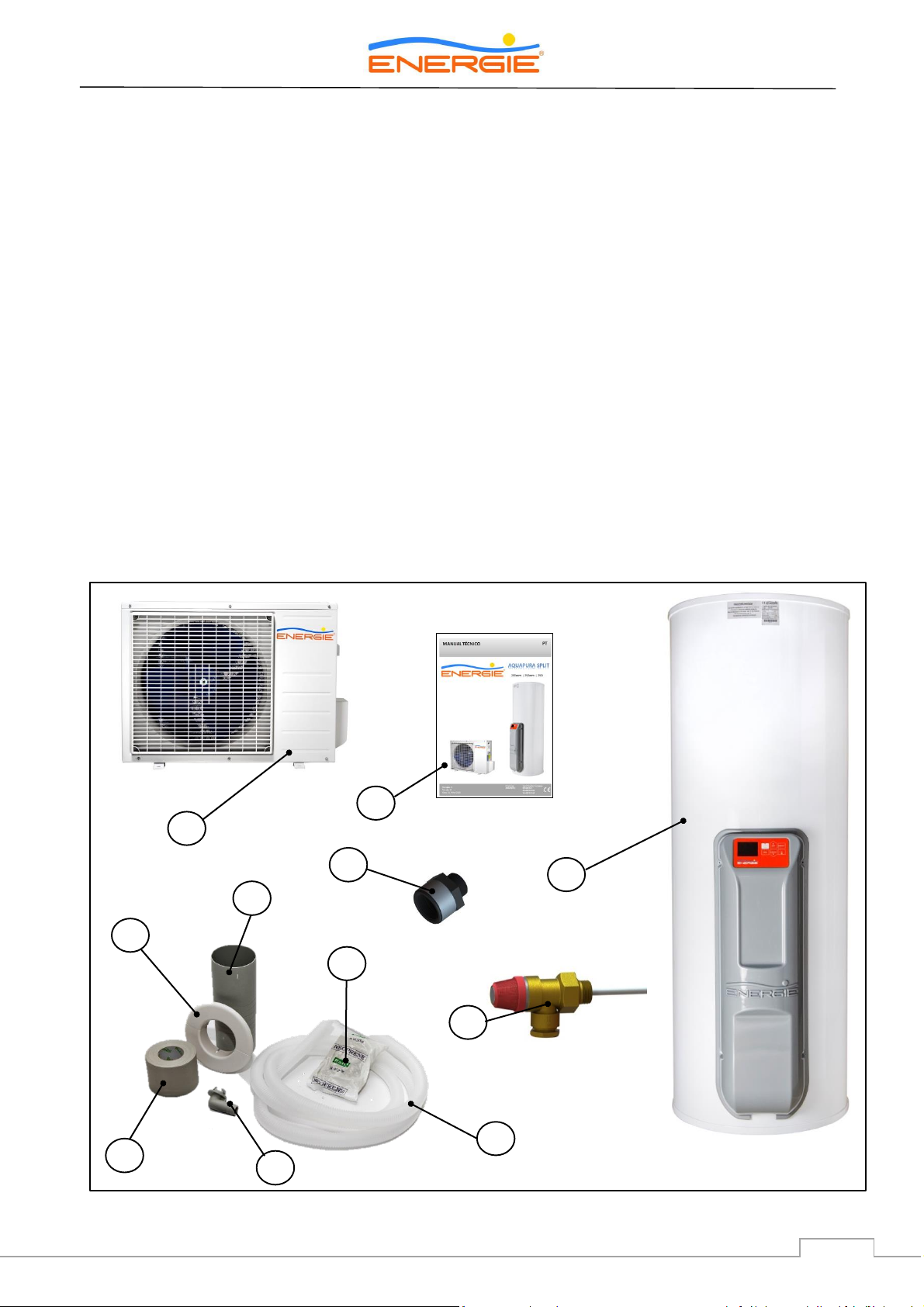
2. Package
2.1. Contents
The equipment is delivered in two packages, each over a wooden pallet, with protection units and wrapped
in cardboard.
The package contains:
I. An external unit (Heater-Pump) and its components:
II. Paste for sealing the space between the piping sleeve and the wall
III. Bush for draining the condensate.
IV. Insulation tape roll for the tubes
V. Tube for draining condensate
VI. Piping sleeve
VII. Washer for piping shaft
VIII. An internal unit (Storage Water Heater + Hood)
IX. Two dielectric joint 3/4” (connection with storage water heater)
X. TP valve
XI. Installation Manual
AquaPura Split
8
Technical Manual
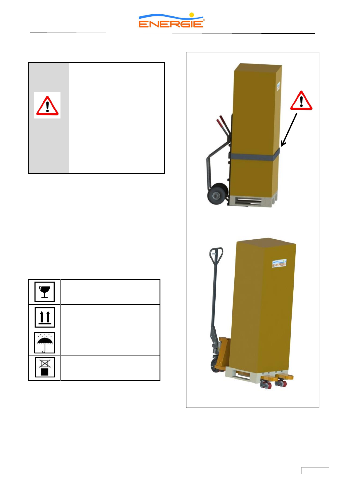
WARNING
Transporting the equipment
must be carried out with an
inclination below 45º;
The equipment must be raised
and lowered to avoid impact
that could damage the
material;
Make sure the belts and/or
transportation straps do not
damage the material;
Always use means of
transportation suitable for the
equipment (pallet lift, forklift,
etc…)
Fragile, handle with extreme
caution
Make sure the arrows are always
up
Keep the package dry
Do not stack packages
2.2. Transport
The equipment must be transported in its original
package to the place of installation. Check, before
beginning transport of the external unit, if the
path you will travel is unobstructed, in order to
prevent collisions that could cause damage to the
device.
The packages contain the following information
symbols:
AquaPura Split
9
Technical Manual
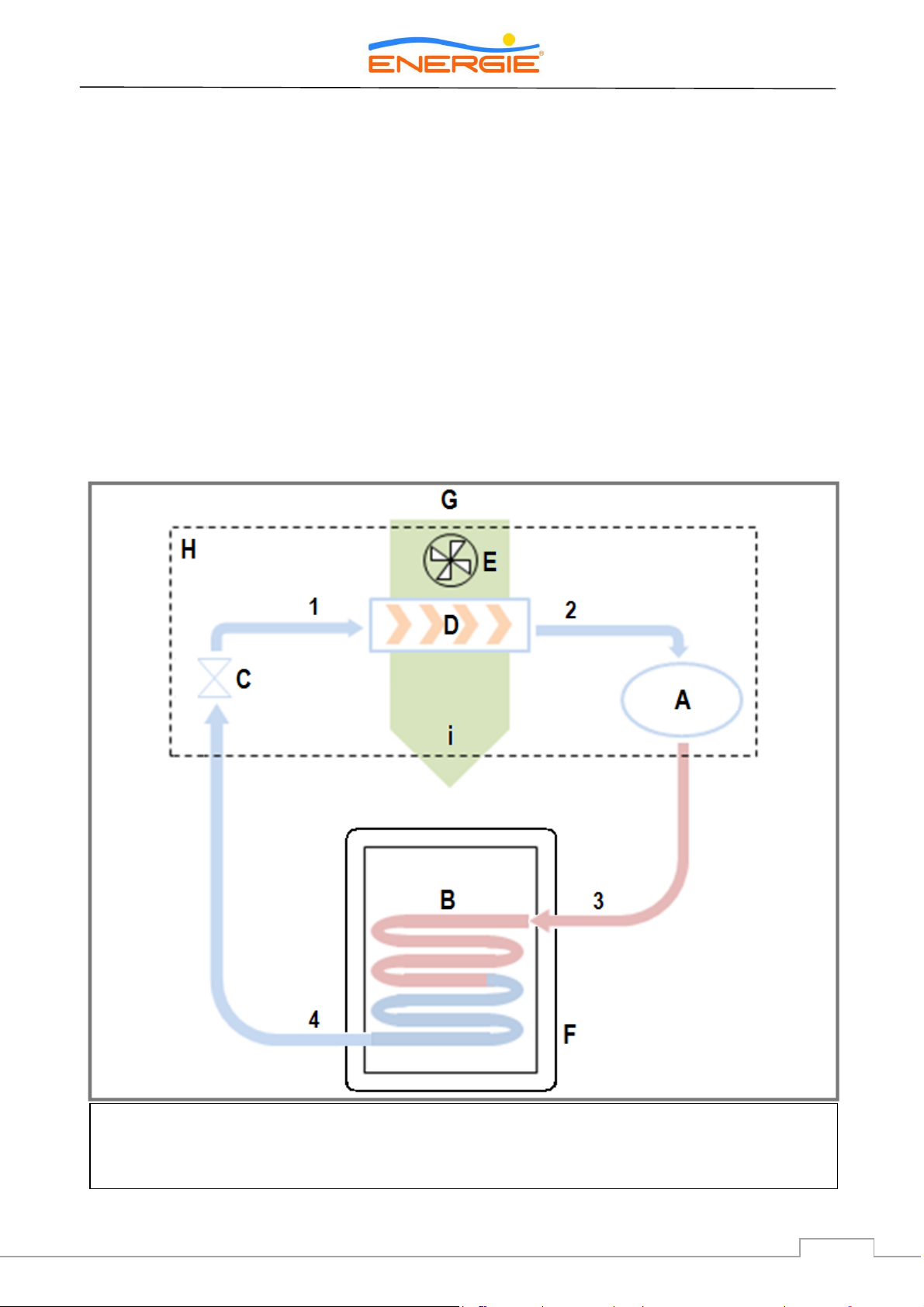
A → Compressor B → Condenser C → Expansion Valve D → Evaporator
E → Fan F → Storage water heater G → Environment H → External Unit
3. Specifications
3.1. Running Principle
The heater-pump AquaPura Split employs
environmental air to heat sanitary water.
The cooling fluid in the heater-pump runs a
thermodynamic cycle that enables the
transference of energy from the environmental air
to the water contained in the storage water
heater.
G-i The air from the environment is forced
through the external unit of the device by a fan.
1-2 When it crosses the evaporator, the cooling
fluid collects the heat from the environmental
heat.
2-3 The compressor aspirates and compresses the
cooling fluid and raises the temperature to a quite
high degree.
3-4 The heat produced by the compressor is
transferred to the condenser that remains in
contact with the sanitary water in the storage
water heater.
4-1 The cooling fluid expands when going through
the expansion valve, and is now ready to collect
the energy present in the environmental air in the
evaporator.
AquaPura Split
10
Technical Manual
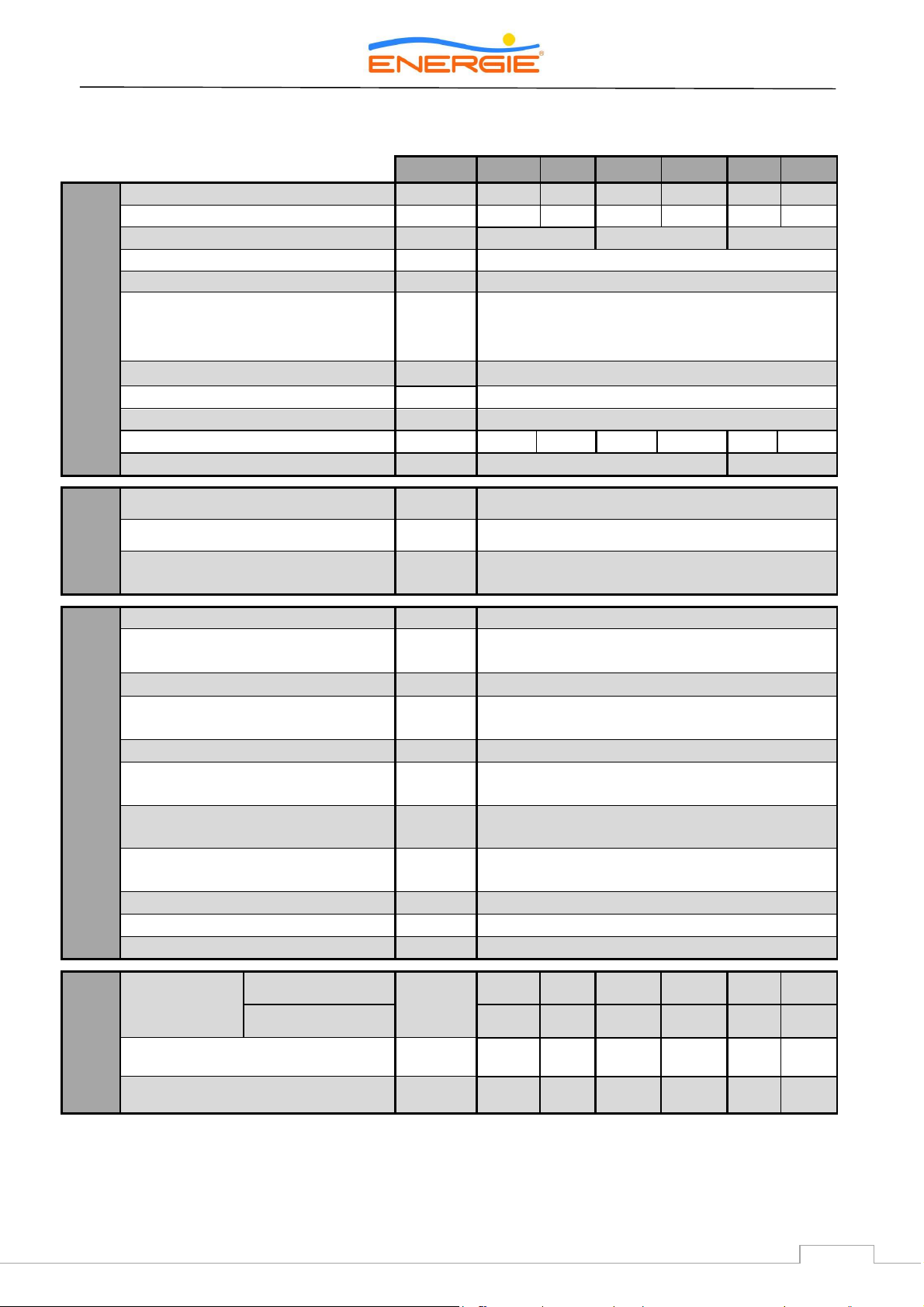
Unit
250 i
300i
200esm
250esm
250ix
300ix
STORAGE HEATER
Dry weight
Kg
62
74
73
83
69
81
Volume
lts
250
300
200
250
250
300
Type of Internal Protection
Stainless steel
Enamel
Stainless steel
Cathodic Protection
Magnesium Anode
Insulation
Polyurethane
Hydraulic Connections
(Cold water | Hot water | PT Valve |
Recirculation | Coil inlet* | Coil outlet*)
Pol.
3/4" Male | 3/4" Male |1/2" Female | 3/4" Male |
1” Male* | 1" Male*
*only on 250ix and 300ix versions
Refrigeration Connections
Pol.
1/4" & 3/8", flare type
Maximum Pressure
bar
7
Maximum Temperature
°C
80
Heat Loss1
kWh/24h
1,01
1,17
1,04
1,2
1,01
1,17
Exchanger Output Power2
kW
#######################
a)30,0; b)18,0
EXTERAL
UNIT
Weight
Kg
28
Refrigeration onnections
Pol.
1/4” & 3/8”, flare type
Level of Sound Pressure at Distance
of 5m
dB(A)
33
CHARACTERISTICS
OF EQUIPMENT
Voltage/ Frequency
(V / Hz)
230 Monophase / 50
General fuse (resistance and
electronic circuit-breaker)
A
7
Compressor fuse
A
7
Average Power absorbed by Heat
Pump
W
600
Max power absorbed by Heat Pump
W
1000
Power absorbed by Electrical
Resistance (Support)
W
1500
Max Distance between Refrigeration
Couplings
m
5
Max Gradient between Refrigeration
Couplings
m
3
Min Temperature of External Air
°C
-5
Max Temperature of External Air
°C
42
Cooling Fluid / Amount
3
- / Kg
R 134a / 1,1
PERFORMANCES
Performance
Coefficient
(COP)
According EN255-3
3,5
3,5
3,4
3,5
3,5
3,5
According EN16147
2,9
2,9
2,8
2,9
2,9
2,9
Heating Time
4
(hh:mm)
05:36
06:51
04:31
05:29
05:31
06:45
Amount of Useful Water at 40 °C
5
l
300
356
236
308
291
351
1) According EN12897:2006
2) a) Primary (Tin=90 ºC; Tout=80 ºC); Production DHW (Tin=10 ºC; Tout=60 ºC)
b) Primary (Tin=70 ºC; Tout=60 ºC); Production DHW (Tin=10 ºC; Tout=60 ºC)
3) The amount of fluid must be checked by the installer. In some cases it is necessary to add or remove fluid in order to ensure the
correct running of the system.
4) Temperature of aspirated air: 7 °C; Relative humidity: 89%; Inlet water temperature: 10 °C; (according to EN16147)
5) Water heating from 10 °C to 54 °C; Air temperature: 7 °C; Relative humidity: 89%; (according to EN16147)
3.2. Technical Features
AquaPura Split
11
Technical Manual
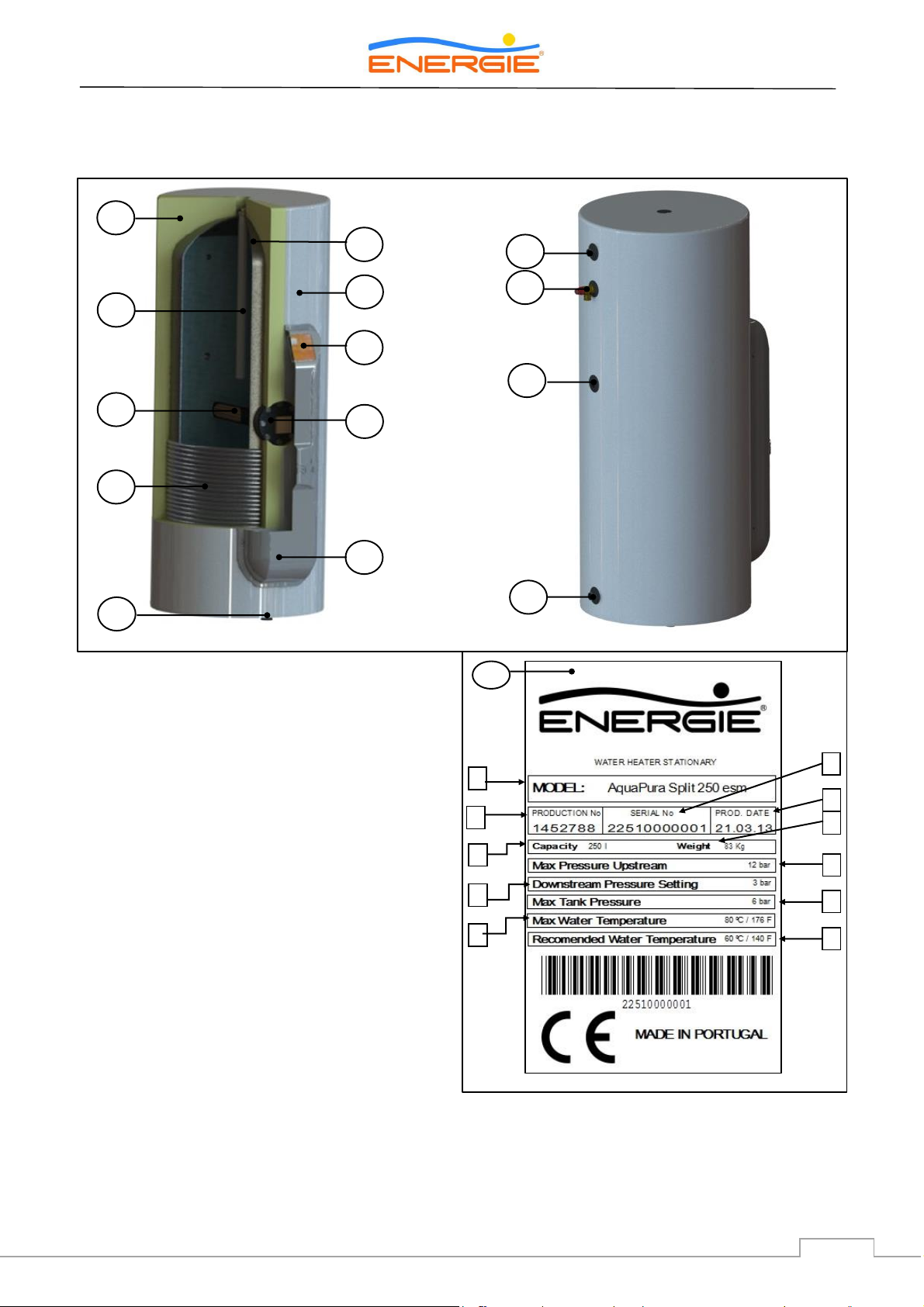
[1]
Adjustable foot
[2]
“Split” hood Top Lid
[3]
Condenser / Serpentine
[4]
Thermostat
[5]
Resistance
[6]
Display
[7]
Magnesium Anode
[8]
External Plate
[9]
Tub
[10]
Polyurethane Insulation
[11]
Cold water inlet + Bipolar Socket
[12]
Recirculation
[13]
TPR Valve
[14]
Hot water outlet + bipolar Socket
[15]
Seal with features (Storage heater)
[A]
Model
[B]
Production Nº
[C]
Series Nº
[D]
Production Date
[E]
Capacity
[F]
Weight
[G]
Downstream pressure of pressure reducing valve
[H]
Upstream Maximum Pressure of pressure reducing valve
[I]
Maximum Pressure in Storage Water Heater
[J]
Maximum Temperature in Storage Water Heater
[L]
Recommended Temperature in Storage Water Heater
1
3
5
7
10
2
4
6
8
9
11
12
13
14
15
C B F H G I J L D A E
15
3.3. Main Components
3.3.1. Internal Unit – Storage Water Heater
AquaPura Split
12
Technical Manual
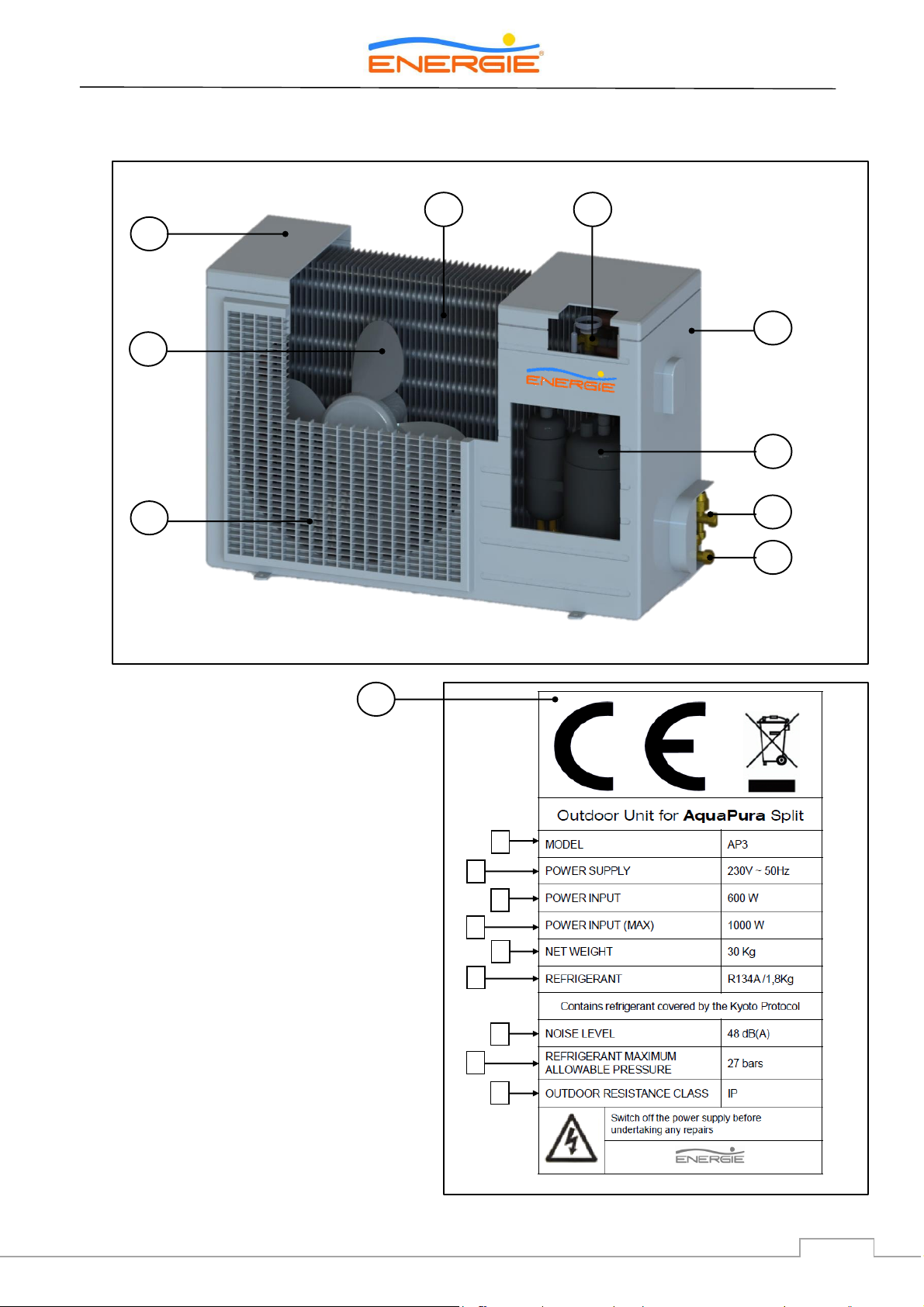
[16]
Top lid
[17]
Fan
[18]
Grill
[19]
Evaporator
[20]
Expanding Valve
[21]
Unit box
[22]
Compressor
[23]
3 way valve (Aspiration)
[24]
2 way valve (Liquid)
[25]
Seal with features (split)
[M]
Model
[N]
Power supply
[O]
Average power consumption
[P]
Maximum power consumption
[Q]
Weight
[R]
Fluid
[S]
Noise level
[T]
Admissible maximum pressure of fluid
[U]
Level of protection
16
17
19
18
20
21
22
23
24
M
N O P Q R
S T U
25
3.3.2. External Unit
 Loading...