

Energic Plus UBC Installation And Safety Instructions
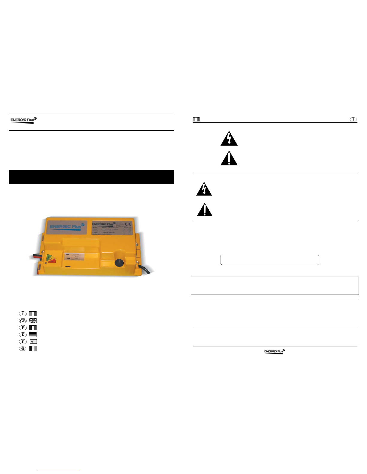
BATTERY CHARGER
CARICA BATTERIA
BATTERY CHARGER
CHARGEUR DE BATTERIE
BATTERIE LADEGERÄT
CARGADOR DE BATERÍA
BATTERIJLADER
UBC
Manuale d’uso e installazione..................................2
Installation and User Manual.....................................8
Manuel d'installation et d'utilisation.....................14
Einbau und Anwenderinformation........................ 20
Manual de uso e instalación..............................................26
Installatie en Handleiding.....................................................38
Italiano Carica batteria UBC
2 D01236-01
ATTENZIONE Non rimuovere
il coperchio: pericolo di scosse elettriche.
Rivolgersi solo a personale autorizzato.
Scollegare l’alimentazione prima di collegare
o scollegare le connessioni alla batteria
Prima dell’utilizzo, leggere attentamente
il libretto di istruzioni. Verificare che
la curva di carica selezionata sia adatta al
tipo di batteria che si deve ricaricare.
Spiegazione dei simboli grafici.
Il simbolo di freccia a forma di fulmine all’interno di un triangolo equilatero avverte l’utente
della presenza di “tensione pericolosa” non isolata dentro il contenitore del prodotto; questa
può essere di ampiezza sufficientemente grande per costituire un rischio di scosse
elettriche per le persone.
Il punto esclamativo all’interno di un triangolo equilatero avverte l’utente della presenza di
importanti istruzioni d’uso e manutenzione (servizio) contenute nella documentazione
allegata al prodotto.
Questa apparecchiatura è coperta da garanzia.
Il relativo certificato di garanzia si trova allegato al libretto di istruzioni.
Se dovesse mancare, richiedetelo al vostro rivenditore.
Per futuri riferimenti, riportate nell’apposito spazio il numero di matricola:
Serial No. _____________________
Le informazioni contenute in questo manuale sono di proprietà della Energic Plus HF
che si riserva di fornirle ad uso esclusivo dei propri clienti. Nessun altro uso è
permesso senza un’autorizzazione scritta emessa dalla Energic Plus HF.
La Energic Plus HF non risponde delle possibili inesattezze, imputabili a errori di
stampa o di trascrizione, contenute nel presente manuale. Si riserva di apportare ai
propri prodotti quelle modifiche che ritenesse necessarie o utili, anche nell’interesse
dell’utenza, senza pregiudicare le caratteristiche essenziali di funzionalità e
sicurezza.
Copyright © 2003 by Energic Plus HF
Seconda Edizione
Carica batteria UBC Italiano
D01236-01 3
Installazione e istruzioni di sicurezza
Il carica batteria UBC è stato progettato per garantire sicurezza e prestazioni affidabili. Tuttavia, onde
evitare danni alla propria persona e al carica batteria, si raccomanda di osservare le seguenti precauzioni
di base:
• Leggere attentamente le istruzioni sull’installazione contenute in questo manuale. Per futuri
riferimenti, riporre il manuale in un posto sicuro.
• Posizionare il carica batteria su una superficie stabile mediante gli appositi fori inseriti sulle flange di
fissaggio. Nel caso di installazione a bordo di un veicolo è consigliabile l’impiego di supporti
antivibrazione.
• Installare preferibilmente in posizione verticale con la ventola rivolta verso l’alto. L’installazione
orizzontale è comunque consentita. Non installare in posizione verticale con la ventola rivolta verso il
basso.
• Per evitare il surriscaldamento, accertarsi che tutte le aperture non siano ostruite. Non posizionare il
carica batteria nei pressi di fonti di calore. Assicurarsi che lo spazio libero intorno al carica batteria sia
sufficiente per garantire un’adeguata ventilazione e un facile accesso alle prese dei cavi.
• Proteggere il carica batterie da eventuali spruzzi d’acqua e non versare liquidi al suo interno.
• Verificare che il tipo di alimentazione a disposizione corrisponda al voltaggio previsto e indicato nella
targhetta del carica batteria. In caso di dubbio, consultare il proprio rivenditore o la società elettrica
locale.
• Come dispositivo di sicurezza e di compatibilità elettromagnetica, il carica batteria dispone di una
spina a tre poli con messa a terra, che può essere inserita soltanto in una presa con messa a terra.
Nel caso in cui non sia possibile inserire la spina nella presa, è molto probabile che la presa a
disposizione sia di un tipo vecchio e non a terra. In tal caso, contattare un elettricista per far sostituire
la presa. Si raccomanda di non usare un adattatore per risolvere il problema della messa a terra.
• Evitare che il cavo di alimentazione sia in una posizione di ingombro. Nel caso in cui il cavo diventi
logoro o subisca danni, sostituirlo immediatamente.
• Nel caso in cui si usi una prolunga o una presa multipla, verificare che queste supportino il totale della
corrente richiesta.
• Scollegare l’alimentazione prima di collegare o scollegare le connessioni alla batteria.
• Per la ricarica di batterie al Piombo: ATTENZIONE: Gas esplosivi - Evitare la formazione di fiamme e
scintille. - La batteria deve essere posizionata in un luogo ben ventilato.
• Non utilizzare per ricaricare batterie installate a bordo di automobili a motore termico.
• Evitare di ricaricare batterie non ricaricabili.
• Verificare che la tensione nominale della batteria da ricaricare corrisponda a quella indicata nella
targhetta del carica batteria.
• Verificare che la curva di carica selezionata sia adatta al tipo di batteria che si deve ricaricare. In caso
di dubbio, consultare il proprio rivenditore. La Energic Plus HF declina ogni responsabilità nel caso di
errore nella scelta della curva di carica che porti a un danneggiamento irreversibile della batteria.
• Per evitare cadute di tensione e così garantire la carica completa della batteria, i cavi di uscita devono
essere più corti possibile e di sezione adeguata alla corrente di uscita.
• Non tentare di effettuare riparazioni sul carica batteria. L’apertura del coperchio potrebbe esporvi al
rischio di scosse elettriche.
• Nell’eventualità che il carica batteria non funzioni in modo corretto o che sia danneggiato, scollegarlo
immediatamente dalla presa di corrente e dalla presa di batteria e contattare il rivenditore.
Italiano Carica batteria UBC
4 D01236-01
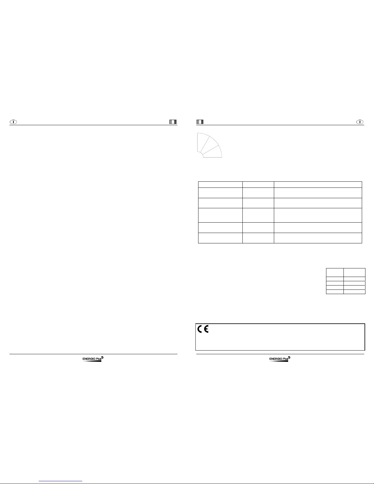
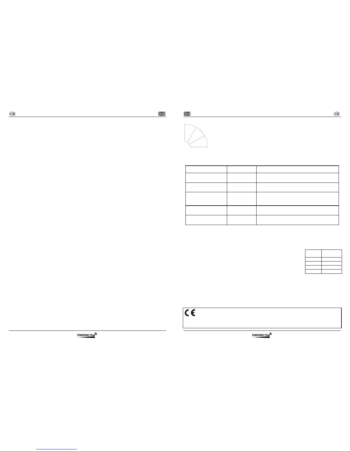
Indicatore a LED
Il LED ROSSO indica che la batteria è nella fase iniziale della carica.
Il LED GIALLO indica che la batteria ha raggiunto l’80% della carica.
Il LED VERDE indica che la batteria ha raggiunto il 100% della carica.
Ulteriori dettagli si trovano nella descrizione della Curva di Carica.
Esempio: Il LED ROSSO acceso con brevi spegnimenti indica una fase a
tensione costante.
Allarmi
Il LED lampeggiante indica che si è verificata una situazione di Allarme.
Condizione Tipo di Allarme Descrizione (Azione)
VERDE lampeggiante Timeout Fase1 di durata superiore ai massimi consentiti.
(Verificare la capacità della batteria).
ROSSO-GIALLO
lampeggianti
Corrente Batteria Perdita del controllo della Corrente di uscita. (Guasto
della logica di controllo).
ROSSO-VERDE
lampeggianti
Tensione Batteria Batteria non conforme (verificare la tensione
nominale) o perdita del controllo della Tensione di
uscita. (Guasto della logica di controllo).
ROSSO-GIALLO-VERDE
lampeggianti
Termico Sovratemperatura dei semiconduttori (Verificare il
funzionamento del ventilatore).
GIALLO-VERDE
lampeggianti
Selezione È stata selezionata una configurazione non
disponibile (Verificare la posizione del selettore).
In presenza di allarme il carica batteria cessa di erogare corrente.
Batteria
Una batteria viene caratterizzata da due grandezze: tensione e capacità.
Tensione:
Ogni elemento ha una tensione nominale che dipende dal tipo di batteria
(indipendentemente dalle sue dimensioni). Per avere tensioni superiori si
collegano in serie più elementi venendo così a costituire una “BATTERIA” di
elementi.
Il numero di elementi si calcola dividendo la tensione nominale della batteria per
la tensione del singolo elemento riportata in tabella:
Capacità:
È la quantità di carica elettrica che le batterie possono fornire a un circuito esterno prima che la tensione
scenda al di sotto del valore limite finale e si ottiene moltiplicando l’intensità della corrente di scarica I
espressa in ampere (A) per il tempo di scarica t espresso in ore (h): C = I × t.
La capacità delle batterie per trazione viene normalmente riferita al regime di scarica di 5h: C5 = I × 5h.
I valori delle capacità che possono essere caricate dal caricabatteria si trovano nella descrizione della
Curva di Carica (tale valore viene omesso nelle curve che possono caricare qualunque capacità).
:
Questa apparecchiatura è conforme ai requisiti della Direttiva Bassa
Tensione 73/23/CEE e della Direttiva EMC 89/336/CEE e loro
successive modificazioni.
Tipo
Tensione
nominale
Pb 2 V/el
NiCd 1,2 V/el
NiMH 1,2 V/el
NiZn 1,714 V/el
8
0
%
1
0
0
%
S
T
A
R
T
Carica batteria UBC Italiano
D01236-01 5
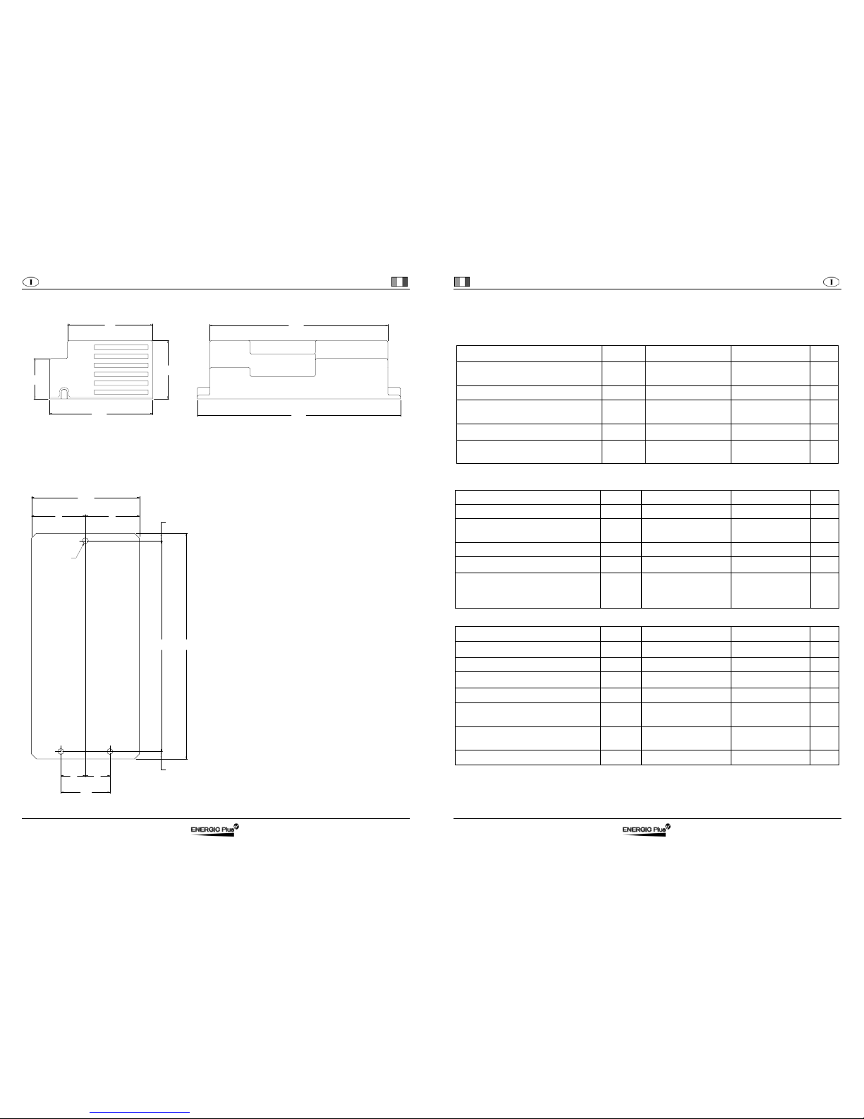
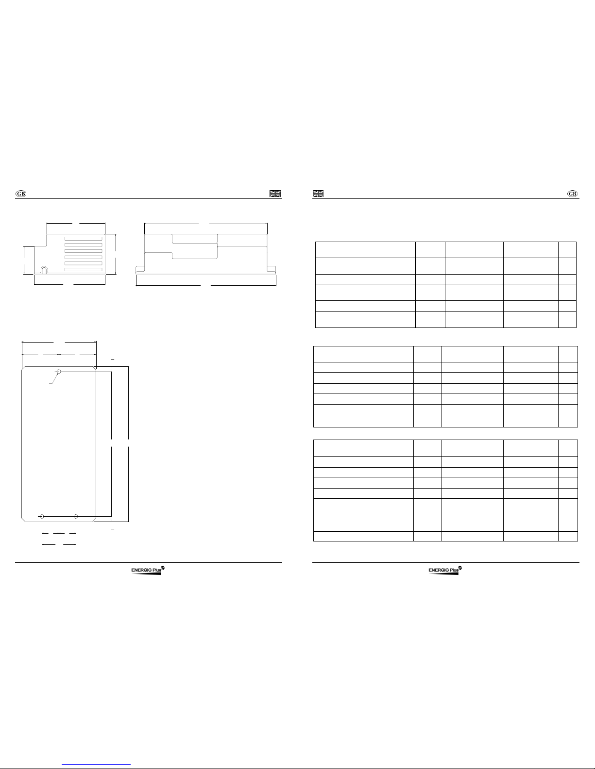
Ingombri meccanici
115
65
95
235
199
45
N.B. Tutte le quote sono in mm.
Dima di foratura
ALTO
Installazione consigliata
N.B. Tutte le quote sono in mm.
215 230
110
= =
50
= =
8
8
Ø 6
Italiano Carica batteria UBC
6 D01236-01
CARATTERISTICHE TECNICHE
Ta=25°C se non diversamente specificato.
Morsetti di Alimentazione
Descrizione Simbolo Condizioni di Test Valore e/o Range Unità
Tensione di Alimentazione Vin - 230 ± 10%
115 ± 10%
Veff
Frequenza f - 50 ÷ 60 Hz
Corrente Massima assorbita
Iin
max
P = P
max
3 @ 230 Veff
4 @ 115 Veff
Aeff
Fattore di Potenza
cosϕ
P = P
max
0,7 -
Potenza Massima assorbita
Pin
max
P = P
max
425 (230 Veff)
340 (115/230 Veff)
W
Morsetti di Batteria
Descrizione Simbolo Condizioni di Test Valore e/o Range Unità
Ondulazione della corrente di uscita - I = I1 < 5% Corrente assorbita
I
a
Apparecchiatura
spenta
< 1 mA
Ondulazione della tensione di uscita - U = U1 < 1% Potenza Massima fornita
P
max
U = U1, I = I1 360 W
Capacità di uscita C - Dipende dal
modello
(>1000)
μF
Generali
Descrizione Simbolo Condizioni di Test Valore e/o Range Unità
Range termico di funzionamento
ΔT
- da -20 a +50 °C
Umidità relativa massima RH - 90% Frequenza di commutazione
f
c
- 150 ± 5% kHz
Rendimento
η
In ogni condizione > 85% -
Dimensioni massime a×b×c Senza cavi di
collegamento
235×115×65 mm
Peso - Senza cavi di
collegamento
850 g
Tipo di protezione - - IP20 -
Carica batteria UBC Italiano
D01236-01 7
Protezioni e Sicurezza
Descrizione Simbolo Condizioni di Test Valore e/o
Range
Unità
Isolamento - Morsetti di Alimentazione e
Morsetti di Batteria
1250 VAC
Isolamento - Morsetti di Alimentazione e
Terra
500 VDC
Isolamento - Morsetti di Batteria e Terra 500 VDC
Corrente di dispersione (leakage)
I
L
Apparecchiatura alimentata < 3 mA
Fusibile di ingresso F1 Interno all’apparecchiatura 7 (ritardato) A
Fusibile di uscita F2 Interno all’apparecchiatura 40 A
Tensione Minima di uscita per il
funzionamento (Sensore di Batteria)
- All’accensione
dell’apparecchiatura
1,3 V/el
Inversione di polarità in uscita - Messa in funzione Protezione
data dal
fusibile F2
-
Protezione termica dei semiconduttori
(Temperatura di Allarme Termico)
- Ta=55°C 100 °C
Prescrizioni (norme) di Sicurezza -
EN60335-1, EN60335-2-29
- -
Prescrizioni (norme) EMC -
EN55014-1, EN61000-3-3
EN55014-2, EN61000-4-2
EN61000-4-4, EN61000-4-5
EN61000-4-6, EN61000-4-11
- -
English Battery charger UBC
8 D01236-01
ATTENTION: To reduce the risk of
electric shock, do not remove cover.
Refer servicing to qualified service personnel.
Disconnect the mains supply before connecting
or disconnecting the links to the battery.
Read the Instruction Manual carefully
before use. Verify that the selected
charge curve is suitable for the type
of battery You have to re-charge.
Explanation of Graphical Symbols
The lightning flash with arrowhead symbol, within an equilateral triangle, is intended to alert
the user to the presence of uninsulated “dangerous voltage” within the equipment’s enclosure;
that may be of sufficient magnitude to constitute a risk of electric shock to persons.
The exclamation point within an equilateral triangle is intended to alert the user to the
presence of important operating and maintenance (servicing) instructions in the literature
accompanying the equipment.
This product is covered by warranty.
The relative warranty certificate is attached to the Instructions Manual.
If the Manual is not provided with this certificate, please ask your retailer for a copy.
For further references, please write the serial number in the proper space:
Serial No. _____________________
Information contained in this Manual relates to Energic Plus HF property which
reserves the right to supply for the exclusive use of customers.
No other use is allowed without a written authorization supplied by Energic Plus HF
Energic Plus HF will be not responsible for inaccuracies contained in this manual
due to print or translation errors. Energic Plus HF has the right to make changes or
improvements, also for the user interest, without prejudicing the essential
characteristic of operation and safety.
Copyright © 2003 by Energic Plus HF
Second Edition
Battery charger UBC English
D01236-01 9
Installation and safety instructions
Battery charger UBC has been designed to provide safety and reliable. It is necessary to observe the
following precautions in order to avoid damage to persons and to the battery charger:
• Read the installation instructions contained in this Manual carefully. For further information put the
Manual in a proper place.
• Fix the battery charger to a stable surface through the appropriate holes inserted on the fixing flanges.
In case of installation on a vehicle it is advisable to use antivibration supports.
• Preferably the charger should be installed in the vertical position with the fan facing up. The horizontal
installation is allowed. Never install in the vertical position with the fan facing down.
• Ensure all ventilation ports are not obstructed, to avoid the overheating. Do not put the battery charger
near heat sources. Make sure that free space around the battery charger is sufficient to provide
adequate ventilation and an easy access to cables sockets.
• Protect the battery charger from ingress of water. Do not pour liquids inside the case.
• Verify that the available supply voltage corresponds to the voltage that is stated on the battery charger
name plate. In case of doubt, consult a retailer or local Electric Supply Authority.
• For safety and electromagnetic compatibility, the battery charger has a 3-prong plug as a safety
feature, and it will only fit into an earthed outlet. If you can not plug it in, chances are you have an
older, non-earthed outlet; contact an electrician to have the outlet replaced. Do not use an adapter to
defeat the earthing.
• To avoid damaging the power cord, do not put anything on it or place it where it will be walked on. If
the cord becomes damaged or frayed, replace it immediately.
• If you are using an extension cord or power strip, make sure that the total of the amperes required by
all the equipment on the extension is less than the extension’s rating.
• Disconnect the mains supply before connecting or disconnecting the links to the battery.
• To recharge Lead Acid batteries: WARNING: Explosive Gas – Avoid flames and sparks. The battery
must be positioned in a correctly cooled place.
• Do not use to charge batteries installed on board of thermal engine cars.
• Avoid recharging of non-rechargeable batteries.
• Verify that the nominal voltage of the battery to be re-charged corresponds to the voltage stated on
the battery charger name plate.
• Verify that the selected charging curve is suitable for the type of battery to be re-charged. In case of
doubt, consult Your retailer. Energic Plus HF will not accept any responsibility in case of mistaken
choice of the charging curve that may cause irreversible damage to the battery.
• In order to avoid voltage drop, thereby assuring 100% charge at the battery, the output cables must
be as short as possible, and the diameter must be adequate for the output current.
• Do not try to service the battery charger yourself. Opening the cover may expose you to shocks or
other hazards.
• If the battery charger does not work correctly or if it has been damaged, unplugged it immediately
from the supply socket and from the battery socket and contact a retailer.
English Battery charger UBC
10 D01236-01
LED Indicator
RED LED shows that the battery is in initial charging phase.
YELLOW LED shows that the battery charger has reached 80% of charge.
GREEN LED shows that the battery has reached 100% of charge.
Further information can be found in the description of the Charging Curve.
Example: the RED LED on blinking indicates a constant tension phase.
Alarms
The flashing LED shows that an Alarm situation has occurred:
Condition Alarm Type Description (Action)
GREEN flash Timeout
Phase 1 have a duration in excess of the maximal
allowed. (Verify the battery capacity).
RED-YELLOW flash Battery Current
Loss of output Current control. (Failure of the control
logic).
RED-GREEN flash Battery Voltage
Battery not in conformity (verify the nominal voltage)
or loss of output Voltage control. (failure of the control
logic).
RED-YELLOW-GREEN
flash
Thermal
Overheating of semiconductors. (Verify the fan
operation).
YELLOW-GREEN flash Selection
An unavailable configuration has been selected
(Verify the selector’s position)
When there is an alarm the battery charger stops supplying current.
Battery
A battery is characterised by two sizes: tension and capacity.
Tension:
Each element has a nominal tension, which depends on the type of battery (no
matter what size).
In order to reach higher tension, many elements are connected in series, so
creating a “BATTERY” of elements.
The number of elements is calculated by dividing the nominal tension of the
battery for the tension of each single element in the table:
Capacity:
It is the quantity of electric charge that the batteries can supply to an external circuit before the tension
decreases under the final limit value and it is obtained by multiplying the intensity of the discharging
current I, expressed in ampere (A), for the discharging time t expressed in hours (h): C = I x t
The traction battery capacity is normally referred to the discharging system of 5h: C5 = I x 5h.
The capacity values that can be recharged by the battery chargers can be found in the description of the
Charging Curve (this value is not present in the curves able to charge any capacity).
:
This device is in conformity with the Low Voltage directive 73/23/EEC
and EMC directive 89/336/EEC and their further modifications.
Type
Nominal
Tension
Pb 2 V/cell
NiCd 1,2 V/cell
NiMH 1,2 V/cell
NiZn 1,714 V/cell
8
0
%
1
0
0
%
S
T
A
R
T
Battery charger UBC English
D01236-01 11
Mechanical dimensions
115
65
95
235
199
45
N.B. All dimensions are expressed in mm.
Drilling details
UP
Advised Installation
N.B. All dimensions are expressed in mm.
215 230
110
= =
50
= =
8
8
Ø 6
English Battery charger UBC
12 D01236-01
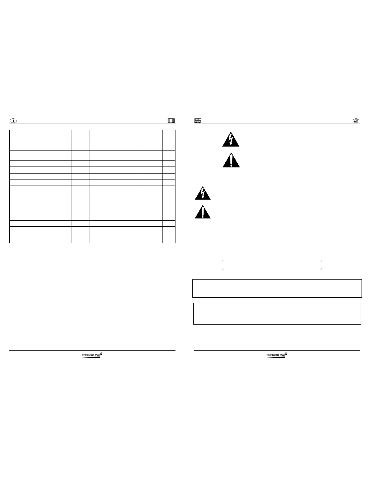
TECHNICAL FEATURES
Ta=25°C unless otherwise specified.
Mains side
Description Symbol Test Condition
Value and/or
Range
Unit
Supply Voltage
Vin - 230 ± 10%
115 ± 10%
Veff
Frequency f - 50 ÷ 60 Hz
Absorbed Maximum Current
Iin
max
P = P
max
3 @ 230 Veff
4 @ 115 Veff
Aeff
Power Factor
cosϕ
P = P
max
0,7 -
Absorbed Maximum Power
Pin
max
P = P
max
425 (230 Veff)
340 (115/230 Veff)
W
Battery side
Description Symbol Test Condition
Value and/or
Range
Unit
Output current ripple - I = I1 < 5% Absorbed current
I
a
Equipment turned off < 1 mA
Output voltage ripple - U = U1 < 1% Maximum power supplied
P
max
U = U1, I = I1 360 W
Output capacity C - Depend on the
model
(>1000)
μF
General
Description Symbol Test Condition
Value and/or
Range
Unit
Operating range of temperature
ΔT
- from -20 to +50 °C
Maximum relative humidity RH - 90% Switching frequency
f
c
- 150 ± 5% kHz
Efficiency
η
At each condition > 85% -
Maximum size a×b×c Without connecting
cable
235×115×65 mm
Weight - Without connecting
cable
850 g
Enclosure class - - IP20 -
Battery charger UBC English
D01236-01 13
Protection and Safety
Description Symbol Test Condition
Value and/or
Range
Unit
Insulation - Mains to Battery side 1250 VAC
Insulation - Mains side to Earth 500 VDC
Insulation - Battery side to Earth 500 VDC
Leakage current
I
L
Supplied equipment < 3 mA
Input fuse F1 Inside the equipment 7 (delayed) A
Output fuse F2 Inside the equipment 40 A
Minimum output voltage of operation
(Battery Detector)
- Equipment turn on 1,3 V/cell
Reverse output polarity - At the connection to the
Battery
Protection
provided by
fuse F2
-
Thermal protection of semiconductors
(Temperature of Thermal Alarm)
- Ta=55°C 100 °C
Safety Requirements (Rules) -
EN60335-1, EN60335-2-29
- -
EMC Requirements (Rules) -
EN55014-1, EN61000-3-3
EN55014-2, EN61000-4-2
EN61000-4-4, EN61000-4-5
EN61000-4-6, EN61000-4-11
- -
Français Chargeur de batterie UBC
14 D01236-01
ATTENTION Ne pas enlever le couvercle:
danger de décharge électrique.
S'adresser seulement à une personne autorisée.
Déconnecter l’alimentation avant de connecter
Ou déconnecter les connexions de la batterie.
Avant de l'utiliser, lire attentivement le livre d'instruction.
Vérifier que la courbe de charge sélectionnée est adaptée
au type de la batterie qui doit être chargée.
Spécification des symboles graphiques.
Le symbole de flèche en forme d'éclair à l'intérieur d'un triangle équilatéral averti l'utilisateur
de la présence de "tension dangereuse" non isolée à l'intérieur du boîtier du produit ; cela
peut-être d'ampleur suffisamment grande pour constituer un risque de décharges électriques
pour les personnes.
Le point d'exclamation à l'intérieur d'un triangle équilatéral averti l'utilisateur de la présence
d'importantes instructions d'utilisation et de manutention (service) contenues dans la
documentation jointe au produit.
Cet appareil est couvert par la garantie.
Le certificat relatif de garantie se trouve joint au livret d'instruction.
S'il manque, en faire la demande auprès de votre revendeur.
Pour de futures références, apposer ci après le numéro de matricule:
Serial No. _____________________
Les informations contenues dans ce manuel sont la propriété de la société Energic
Plus HF qui se réserve de la fournir à l'usage exclusif de ses propres clients. Aucune
autre utilisation n'est permise sans l'autorisation écrite de Energic Plus HF.
La société Energic Plus HF ne répond pas des possibles inexactitudes imputables à
des erreurs d'impressions ou de traduction contenue dans le présent manuel. Elle se
réserve d'apporter, à ses propres produits des modifications qui s'avèrent
nécessaires ou utiles, ou même dans l'intérêt de l'utilisateur, sans nuire aux
caractéristiques essentielles de fonctionnement et de sécurité.
Copyright © 2003 by Energic Plus HF
Second Édition
 Loading...