

Page 1
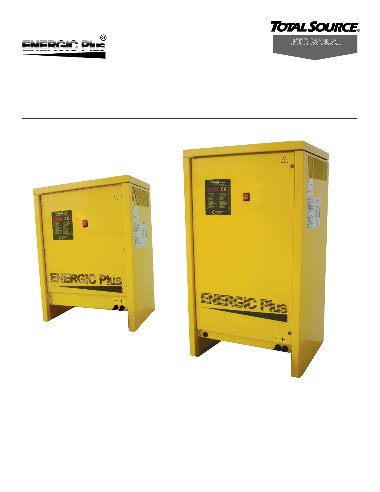
Operating Instructions
User ManUal
TST-D Battery Chargers
Users Manual 2013
www.energicplus.com
1
Page 2

INDEX
SAFETY INSTRUCTIONS AND WARNINGS . . . . . . . . . . . . . . . . . . . . . . . . . . . . . . . 3
GENERAL . . . . . . . . . . . . . . . . . . . . . . . . . . . . . . . . . . . . . . . 3
SHOCK PREVENTION . . . . . . . . . . . . . . . . . . . . . . . . . . . . . . . . . . 3
BURN AND BODILY INJURY PREVENTION . . . . . . . . . . . . . . . . . . . . . . . . 4
FIRE AND EXPLOSION PREVENTION . . . . . . . . . . . . . . . . . . . . . . . . . . . 4
ARCING AND BURNING OF CONNECTOR . . . . . . . . . . . . . . . . . . . . . . . . 4
MEDICAL AND FIRST AID TREATMENT . . . . . . . . . . . . . . . . . . . . . . . . . . . . . . . . 4
DESCRIPTION OF THE CHARGER . . . . . . . . . . . . . . . . . . . . . . . . . . . . . . . . . . . . 5
INSTALLATION OF THE CHARGER . . . . . . . . . . . . . . . . . . . . . . . . . . . . . . . . . . . . 6
INTERNAL VIEW OF THE CHARGER, CABINET A . . . . . . . . . . . . . . . . . . . . . . 7
INTERNAL VIEW OF THE CHARGER, CABINET B . . . . . . . . . . . . . . . . . . . . . . 8
AC VOLTAGE SELECTION 3 x 240/480 V (not for 600V input models) . . . . . . . . . . . . 9
AC INPUT VOLTAGE ADJUSTMENT . . . . . . . . . . . . . . . . . . . . . . . . . . . . 9
GROUNDING AND LINE CONNECTION . . . . . . . . . . . . . . . . . . . . . . . . 10
HOW TO USE THE CHARGER . . . . . . . . . . . . . . . . . . . . . . . . . . . . . . . . . . . . . . 11
PRELIMINARY CHECKS . . . . . . . . . . . . . . . . . . . . . . . . . . . . . . . . .11
BATTERY CONNECTION, VOLTAGE CHECK AND AUTOSTART . . . . . . . . . . . . . . 12
CHARGE PROCESS . . . . . . . . . . . . . . . . . . . . . . . . . . . . . . . . . . 13
AUTOMATIC DATA SAVING . . . . . . . . . . . . . . . . . . . . . . . . . . . . . . 14
AUTOMATIC AND MANUAL CHARGE TERMINATION . . . . . . . . . . . . . . . . . . 14
EQUALIZATION . . . . . . . . . . . . . . . . . . . . . . . . . . . . . . . . . . . 15
MAINTENANCE . . . . . . . . . . . . . . . . . . . . . . . . . . . . . . . . . . . 16
TROUBLE SHOOTING . . . . . . . . . . . . . . . . . . . . . . . . . . . . . . . . . . . . . . . . . . . 17
2
Page 3

SAFETY INSTRUCTIONS AND WARNINGS
Before you start using your Energic Plus battery charger, please take the time to read these
instructions carefully.
The owner’s manual is an important part of the charger. It’s recommended to keep it in good
condition for the lifetime of the charger. It should be kept in a dry and clean place, always
available to the users.
To indicate important instructions, the following blocks are used throughout this manual.
CAUTION!
This operation can be dangerous for the user.
ATTENTION!
This operation is important for the functionality and reliability of the charger.
GENERAL
Battery charging products can cause serious injury or death, or damage to other equipment or property, if
the operator does not strictly observe all safety rules and take precautionary actions. Safe practices must
be learned through study and training before using this equipment. Only qualied personnel should install,
use, or service this equipment.
SHOCK PREVENTION
Bare conductors, or terminals in the output circuit, or ungrounded, electrically-live equipment can fatally
shock a person. To protect against shock, have competent electrician verify that the equipment is adequately
grounded and learn what terminals and parts are electrically HOT.
The body’s electrical resistance is decreased when wet, permitting dangerous current to ow through the
body. Do not work in damp area without being extremely careful. Stand on dry rubber mat or dry wood and
use insulating gloves when dampness or sweat cannot be avoided. Keep clothing dry.
INSTALLATION AND GROUNDING - A power disconnect switch must be located at the equipment.
Check the data label for voltage and phase requirements. If only 3-phase power is available, connect single-phase equipment to ONLY TWO WIRES of the 3-phase line.
DO NOT CONNECT the equipment grounding conductor to the third live wire of the 3-phase line as this
makes the equipment frame electrically HOT, which can cause a fatal shock. If a grounding conductor is part
of the power supply cable, be sure to connect it to a properly grounded switch box or building ground. If not
part of the supply cable, use a separate grounding conductor. Don’t remove a ground prong from any plug.
Use correct mating receptacles. Check ground for electrical continuity before using equipment. The grounding conductor must be of a size equal to or larger than the size of the line conductors.
CHARGING LEADS – Inspect leads often for damage to the insulation. Replace or repair cracked or worn
leads immediately. Use leads having sucient capacity to carry the operating current without overheating.
Don’t replace the original cables with longer cables. Don’t use additional cables to lenghten the original
connections.
3
Page 4

BATTERY TERMINALS – Do not touch battery terminals while equipment is operating.
SERVICE AND MAINTENANCE – Shut OFF all power at the disconnect switch or line breaker BEFORE
inspecting, adjusting, or servicing the equipment. Lock switch OPEN (or remove line fuses) so that the power
cannot be turned ON accidentally. Disconnect power to equipment if it is to be left unattended or out of
service. Disconnect battery from charger. Keep inside parts clean and dry. Dirt and/or moisture can cause
insulation failure. This failure can result in high voltage at the charger output.
BURN AND BODILY INJURY PREVENTION
The battery produces very high currents when short circuited, and will burn the skin severely if in contact
with any metal conductor that is carrying this current. Do not permit rings on ngers to come in contact
with battery terminals or the cell connectors on top of the battery. Battery acid is very corrosive. Always wear
correct eye and body protection when near batteries.
FIRE AND EXPLOSION PREVENTION
When batteries are being recharged, they generate hydrogen gas that is explosive in certain concentrations
in air (the ammability or explosive limits are 4.1% to 72% hydrogen in air). The spark-retarding vents help
slow the rate of release of hydrogen, but the escaping hydrogen may form an explosive atmosphere around
the battery if ventilation is poor. The ventilation system should be designed to provide an adequate amount
of fresh air for the number of batteries being charged. This is essential to prevent an explosion. Always keep
sparks, ames, burning cigarettes, and other sources of ignition away from the battery recharging area. Do
not break “live” circuits at the terminals of batteries. Do not lay tools or anything that is metallic on top of any
battery.
ARCING AND BURNING OF CONNECTOR
To prevent arcing and burning of the connector contacts, be sure the charger is OFF before connecting or
disconnecting the battery. The ammeter should NOT indicate current ow.
MEDICAL AND FIRST AID TREATMENT
First aid facilities and a qualied rst aid person should be available for each shift for immediate treatment of
electrical shock victims.
EMERGENCY FIRST AID: Call physician and ambulance immediately and use First Aid
techniques recommended by the American Red Cross.
DANGER: ELECTRICAL SHOCK CAN BE FATAL.
If person is unconscious and electric shock is suspected, do not touch person if he or she is
in contact with charging equipment, battery, charging leads, or other live electrical parts.
Disconnect power at wall switch and then use First Aid.
Dry wood, wooden broom, and other insulating material can be used to move cables, if
necessary, away from person.
In case of acid in the eyes, ush very well with clean water and obtain professional medical
attention immediately.
4
Page 5
DESCRIPTION OF THE CHARGER
(about 16% of battery capacity)
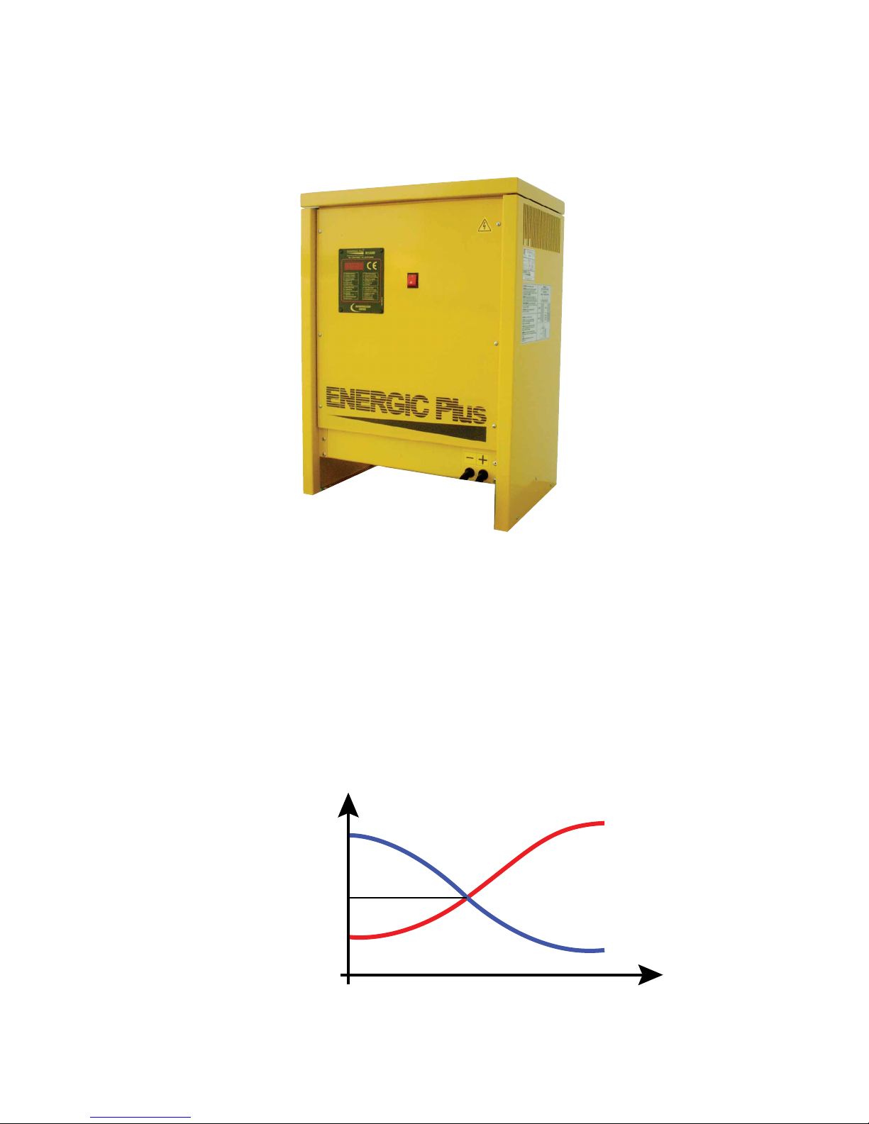
Energic Plus TST-D battery chargers have been designed to charge Pb batteries.
These units convert the AC main supply in a DC output at the correct voltage, in order to
charge the battery cells.
The microprocessor controlled electronic card is used to monitor the state of the charge, and automatically
turn the charger o when the battery is fully charged.
The charge current follows the Wa curve, and the operation is fully automatic.
Current
Voltage
Initial Current
Voltage = 2.40 V/cell
Current = 50% of Initial current
Voltage = 2.00 V/cell
Voltage
Current
Time
5
Page 6

INSTALLATION OF THE CHARGER
Conditions of use:
• Operating temperature: 5°C to 45°C
• Storage temperature: -20°C to 60°C
• Relative humidity: less than 75%
CAUTION!
Risk of electrical shock!
The charger must be installed by qualied personnel only.
To prevent re or shock hazard, do not expose the unit to rain or moisture.
Don’t use the unit in presence of ammable gas, because it can generate sparks.
ATTENTION!
Make sure that the unit’s maximum input power (reported on the data label) is available from
your power supply, and verify that the unit’s operating voltage is correct.
Allow adequate air circulation to prevent internal heat buildup.
Don’t place the unit near heat sources such as radiators or air ducts, or in a place subject to
direct sunlight, excessive dust, mechanical vibration or shock.
ATTENTION!
The proper setting of the power transformer taps is fundamental for the correct
operation of the charger.
If the real AC input voltage is dierent than the AC nominal voltage to which the charger is set,
the charging current of the charger may be signicantly dierent than the nominal current
6
Page 7
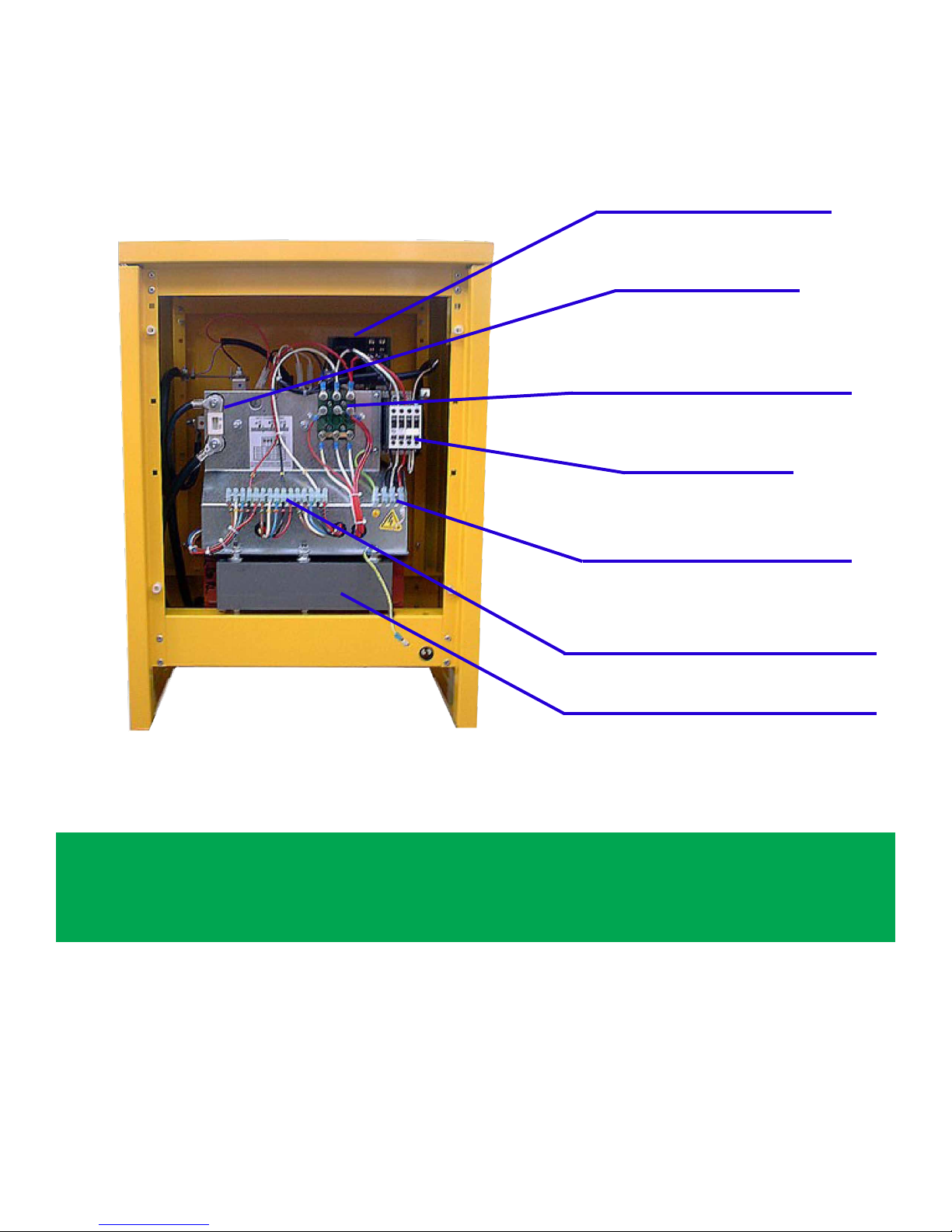
INTERNAL VIEW OF THE CHARGER – CABINET A
CONTROL BOARD
OUTPUT FUSE
BOARD FOR INPUT
VOLTAGE SELECTION
CONTACTOR
TERMINAL BLOCKS
FOR AC INPUT CORD
PLUGS FOR INPUT
VOLTAGE ADJUSTMENT
POWER TRANSFORMER
NOTE
The BOARD FOR INPUT VOLTAGE SELECTION is present only in chargers with
3x 208 / 240 / 480 Vac input, and is not NOT present in chargers with 3x600 Vac input.
The PLUGS FOR INPUT VOLTAGE ADJUSTMENT are present in all the chargers.
7
Page 8
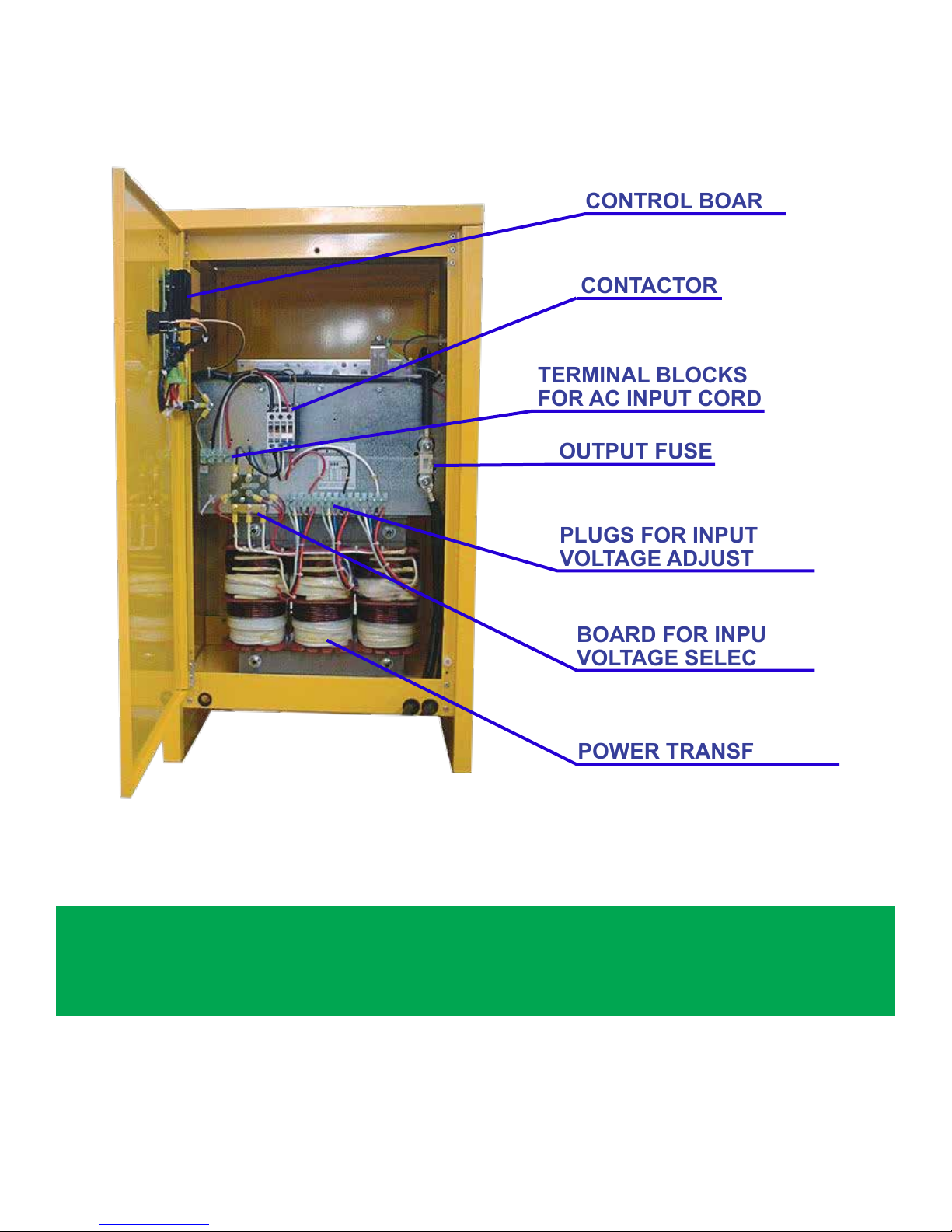
INTERNAL VIEW OF THE CHARGER – CABINET B
TERMINAL BLOCKS
FOR AC INPUT CORD
CONTROL BOARD
CONTACTOR
OUTPUT FUSE
PLUGS FOR INPUT
VOLTAGE ADJUSTMENT
BOARD FOR INPUT
VOLTAGE SELECTION
POWER TRANSFORMER
NOTE
The BOARD FOR INPUT VOLTAGE SELECTION is present only in chargers with
3x 208 / 240 / 480 Vac input, and is NOT present in chargers with 3x600 Vac input.
The PLUGS FOR INPUT VOLTAGE ADJUSTMENT are present in all the chargers.
8
Page 9
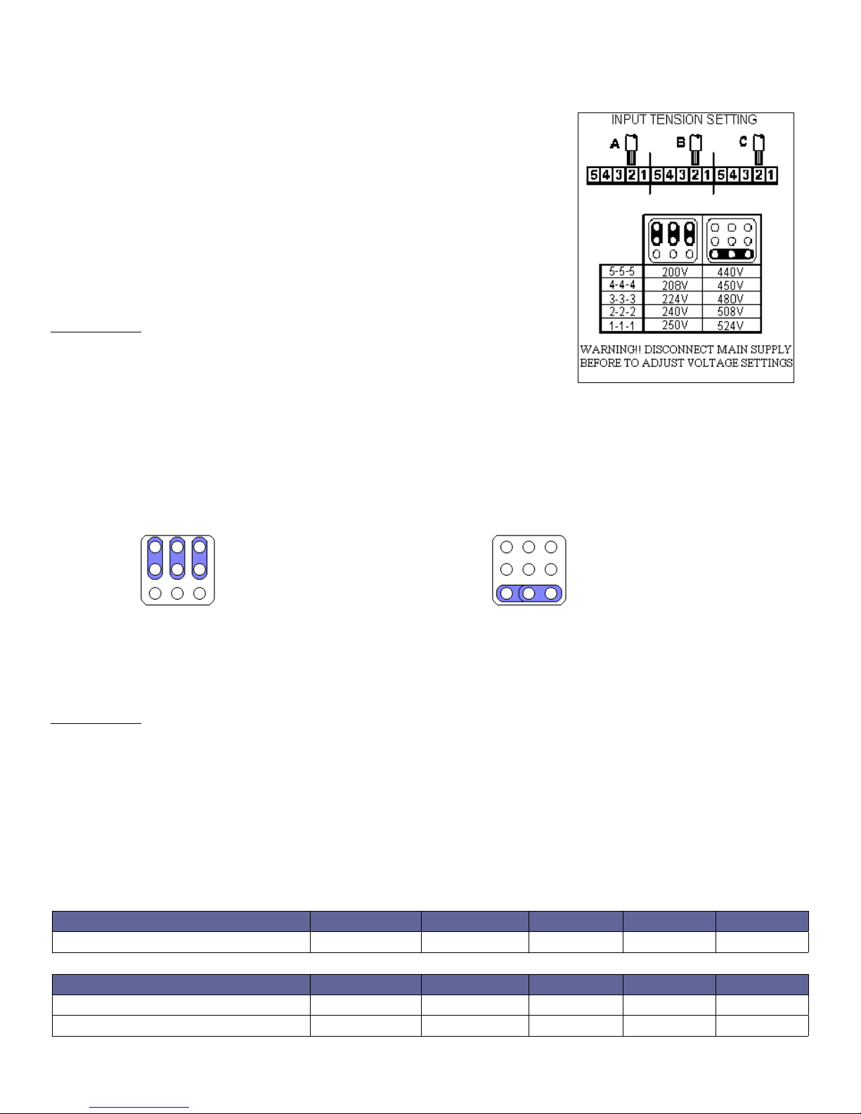
AC VOLTAGE SELECTION 3 x 208/240/480 V (not for 600V input models)
The input voltage setting of the charger is made using two devices:
1) BOARD FOR INPUT VOLTAGE SELECTION (BVS)
(two selectable ranges: 200-250V or 440-524V)
2) PLUGS FOR INPUT VOLTAGE ADJUSTMENT
(ve taps within the selected range, see next chapter)
The BOARD FOR INPUT VOLTAGE SELECTION has three metal
bars, to be connected in one of the two congurations represented
on the picture inside the charger.
PROCEDURE:
• Check that the charger is disconnected from AC input and battery
• Open the cabinet and remove the plastic protection over the BVS
• Remove the metal bars and position them in the correct conguration
• Fix the nuts carefully
• Mount the plastic protection over the BVS
• Close the cabinet
Metal bars in position 200-250 Vac Metal bars in position 440-524 Vac
AC INPUT VOLTAGE ADJUSTMENT
The local AC input voltage must be measured with an adequate voltmeter, then the charger input must be
adjusted by moving the three wires marked with the letters A, B, C on the
PLUGS FOR INPUT VOLTAGE ADJUSTMENT.
PROCEDURE:
• Check that the charger is disconnected from AC input and battery
• Open the cabinet
• Disconnect the wires A, B, C from the original position
• Connect the wire A, B, C to the desired position
• Close the cabinet
MODELS WITH INPUT VOLTAGE 3x600V
POSITION 5 4 3 2 1
VOLTAGE 550V 575V 600V 610V 620V
MODELS WITH INPUT VOLTAGE 3x208/240/480V
POSITION 5 4 3 2 1
BVS AT 240 Vac 200V 208V 224V 240V 250V
BVS AT 480 Vac 440V 450V 480V 508V 524V
9
Page 10

GROUNDING AND LINE CONNECTION
CAUTION!
Risk of electrical shock! The cabinet of the battery charger must be properly grounded to protect
personnel against hazard of electrical shock in case of fault on the charger!
The grounding conductor must have a current carrying capacity equal or higher than the current
carrying capacity of the AC-input wires
If the charger is to be connected to the AC power supply with a exible jacketed cable, one having a separate grounding conductor should be used. If, for any reason, an input cable which does not include a
grounding conductor is used, the equipment must be grounded with separate conductor. Minimum size
and color coding requirements must be in accordance with any applicable national or local code.
PROCEDURE:
• Read on the data label the AC current value corresponding to the line voltage to which charger is to be
connected. Using that current value, select the proper fuses, disconnect switch and power cable sizes,
according with any applicable national or local code
• Check that the charger is disconnected from AC input and battery
• Open the cabinet
• Mount the input cable and connect the four power conductors (three phase + ground) to the terminal blocks
• Close the cabinet
• With disconnect switch on AC input power line on position “OFF” or “OPEN”, connect the power cable
coming from the charger to the switch and, then, install the fuses in the switch
10
Page 11
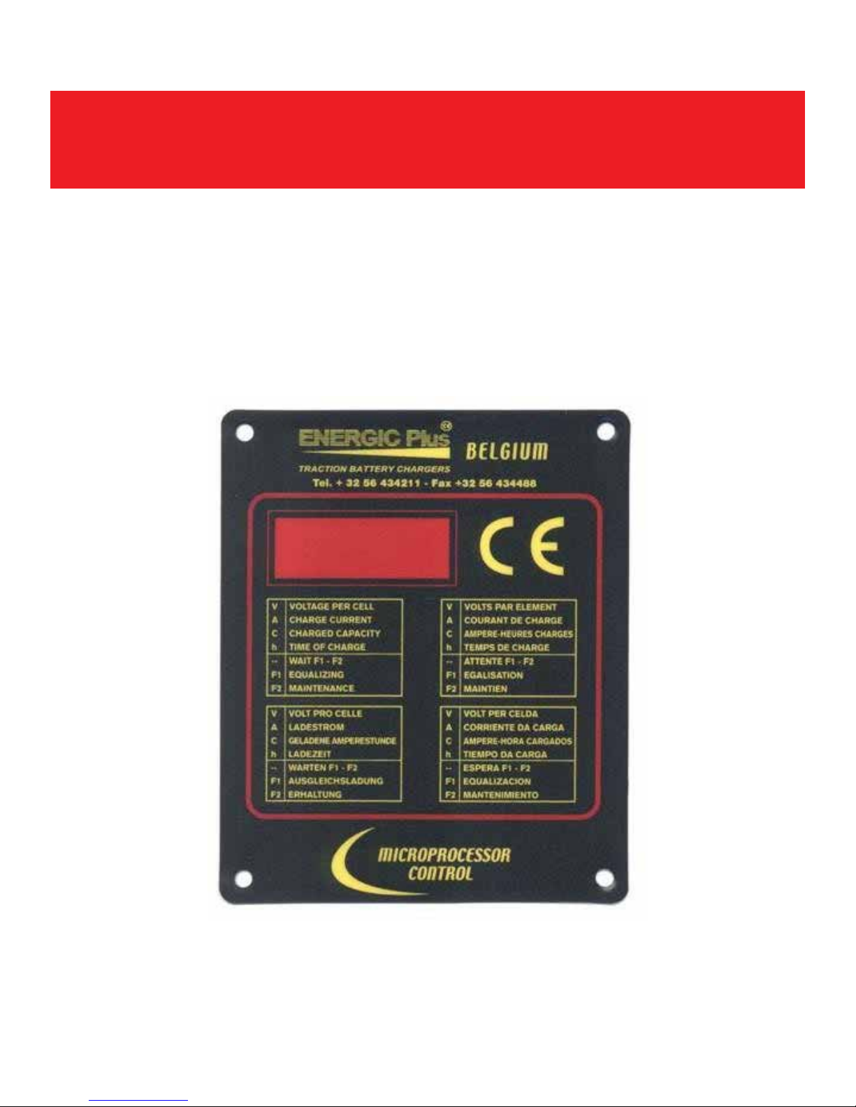
HOW TO USE THE CHARGER
CAUTION!
DON’T connect the battery to the charger if the digital display is ON.
DON’T disconnect the battery from the charger while it is being charged.
ARCING AND BURNING OF CONNECTORS OR BATTERY EXPLOSION MAY RESULT!
PRELIMINARY CHECKS
• Inspect the charger completey for loose screws, electrical connections or other damages;
• Check that all the ventilation slots are not obstructed to assure proper air ow;
• Make sure that the charger is installed as instructed in this manual and in accordance with any applicable
national or local code.
11
Page 12
BATTERY CONNECTION, VOLTAGE CHECK AND AUTOSTART
CAUTION !
ENERGIC Plus chargers are programmed to do a complete cycle of charge
automatically, however it’s always recommended to survey the operations,
especially when the battery is connected to the charger for more than 12 hours.
• Connect the battery to the charger using an adequate connector.
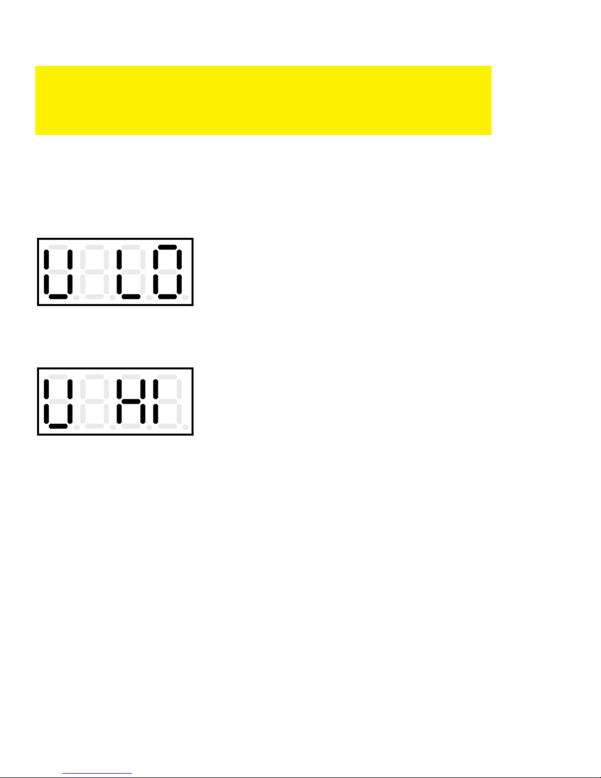
When the battery is correctly connected the display will show the battery voltage.
If the battery voltage is below the minimum threshold of 1.62 V/cell, the charger will not start,
and the display will show the error message “Voltage Low”:
If the battery voltage is higher than the maximum threshold of 2.60 V/cell, the charger will not
start, and the display will show the (ashing) error message “Voltage High”:
If the battery voltage is between the minimum and maximum thresholds the charger will turn
on automatically after 5 seconds.
If, during the charge, the battery voltage exceeds the maximum threshold of 2.80 V/cell, the
charger will shut down automatically, and the errore message “Voltage High” will appear on
the display.
12
Page 13
CHARGE PROCESS
(about 16% of battery capacity)
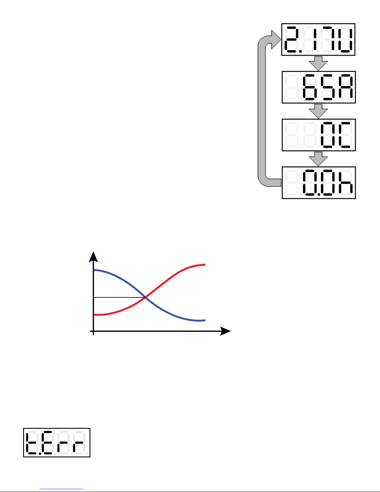
While the charge is in progress the following parameters are
continuously displayed in sequence:
• Battery voltage/cell (Output voltage) (U) (Volt);
• Charge current (Output current) (A) (Ampere);
• Capacity charged (C) (Ah);
• Eective time of charge (h) (Hours);
The letter after the value (U-A-C-h) indicates which parameter
being is displayed.
To display the time the charger uses this format:
(HOURS) . (MINUTE DECADES) h
Examples:
Time of charge 3h 30minutes: Displayed 3.3h
Time of charge 7h 50minutes: Displayed 7.5h
• The charge current follows the Wa curve as described in the norm DIN 41774.
Current
Voltage
Initial Current
Voltage = 2.40 V/cell
Current = 50% of Initial current
Voltage = 2.00 V/cell
Voltage
Current
Time
When the battery reaches the gassing voltage the charge continues for one half of the time
needed to reach the gassing voltage with a minimum total time of 30 minutes.
SAFETY TIMER – EMERGENCY STOP
• If the battery doesn’t reach the gassing voltage within 12 hours, the charge is terminated by
the Emergency timer. The display will show the error message “Time Error”:
13
Page 14

If this error message appears, it’s recommended to call (for service) for a complete check of the system.
The cause if this problem may be a wrong setting of the input voltage: if the input is set to a
certain value (for example: 610 V) but the real voltage is lower (for example: 575 V), the
charging current will be signicantly lower than the nominal value, therefore it will take more
time to reach the gassing voltage.
AUTOMATIC DATA SAVING
• If, while the charge or the equalization is in progress, a black-out of the AC input occurs,
the charger saves automatically all the relevant information about the state of the charge.
While the input power is absent, the message “Black Out” is displayed:
• When the power supply will be available again, the charger will re-start automatically from
the exact point of interruption, and the charge will be normally completed.
AUTOMATIC AND MANUAL CHARGE TERMINATION
CAUTION!
NEVER disconnect the battery while it’s being charged.
Disconnecting the battery while it’s being charged is hazardous for the user and
voids the charger warranty.
• AUTOMATIC CHARGE TERMINATION:
When the charge has been normally completed, the charger turns o automatically.
The display shows the ashing message “End”.
At this point, it’s possible to disconnect the battery.
• MANUAL CHARGE TERMINATION:
The charge can be manually terminated in any moment, by pressing the red STOP
pushbutton. The display will show the message “Stop”:
At this point, it’s possible to disconnect the battery.
14
Page 15

NOTE
After the charge termination, while the battery remains connected, the nal values of
[Voltage/cell], [Time] and [Capacity charged] remain stored in memory.
If the red STOP pushbutton is pressed, the display will show these values in sequence.
If the charge has been terminated manually, equalization and
maintenance functions are automatically disabled.
EQUALIZATION
CAUTION!
NEVER disconnect the battery while it’s being charged.
Disconnecting the battery while it’s being charged is hazardous
for the user and voids the charger warranty.
The EQUALIZATION function is useful to keep all the cells of the battery at the same voltage level, even
after years of continuous work. When a battery is charged/discharged everyday, it’s suggested to equalize it
weekly.
The charger, after a normally completed charge cycle, will add 4 extra charges of 30 minutes, with 15 hours
interval between each charge.
During the interval between each equalization charge, the display will show the scrolling message: “End”:
When the equalization chargers are in progress, the display will show the message“F1”, followed by the
current value:
15
Page 16
MAINTENANCE
The MAINTENANCE function is useful to keep the battery in perfect condition when it’s not
used for an indened time (weeks, months, ...).
It is sucient to leave the battery connected to the charger: the control board will keep the
battery voltage under control and will activate the charger automatically when the voltage falls
below a predened minimum threshold.
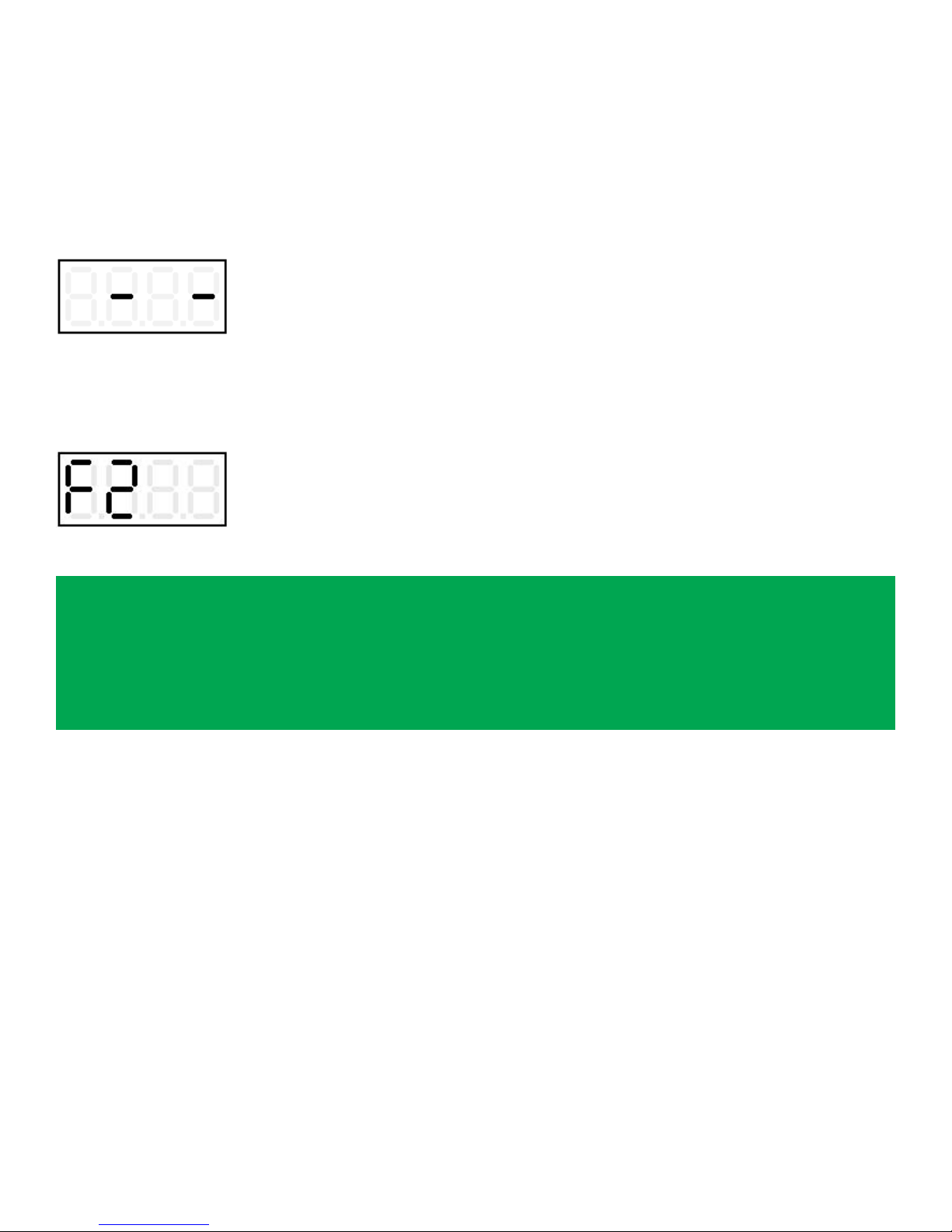
While the charger is o and the battery voltage is being monitored, this message is displayed:
If the voltage falls below the minimum threshold, the charger will give a refresh charge to pull up the
voltage to a programmed maximum threshold, and the display will show the message:
“F2”.
NOTE
With this “voltage controlled” maintenance/refresh system, the battery will be kept in perfect condition for an undened time, without any risk of undercharge or overcharge.
If the battery is in ideal condition (no self-discharge) the refresh charge will never be activated.
If the battery is in bad condition (self-discharge is signicant), the refresh charge will be often activated and the battery will be kept charged without problems.
16
Page 17
TROUBLE SHOOTING
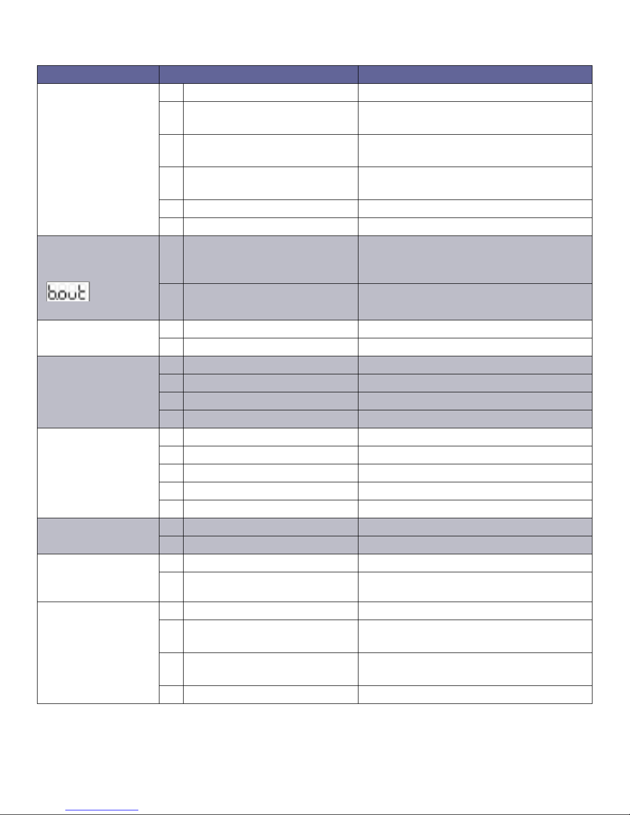
SYMPTOM POSSIBLE CAUSES ACTION
Charger does not
react to battery being connected, and
display remains OFF.
When battery is
connected,
message
appears.
Output current is too
high
Output current is too
low
1 Battery not connected properly. Check battery connectors/harness.
2 Charger has been connected to
forklift motor connector.
Disconnect forkift motor and connect
battery.
3 Output fuse blown. Replace output fuse and adjust AC input
settings.
4 Output cables reversed. Check charger, connectors and battery
polarities. Output fuse is probably blown.
5 Bad control board connection. Check board connectors (green).
6 Bad control board. Replace control board.
1 AC input is absent. Check AC input voltage on each phase.
Check AC input connections. Check AC
disconnect switch and fuses.
2 Bad contactor. Replace contactor and freewheeling diode.
1 Wrong AC input settings. Adjust AC input settings to higher voltage.
2 One or more cells are shorted. Repair battery.
1 Wrong AC input settings. Adjust AC input settings to lower voltage.
2 One AC phase is absent. Check AC input voltage on each phase.
3 One or more diodes blown. Replace rectier.
4 Bad contactor. Replace contactor.
Charger smells hot 1 Bad location. Install the charger in proper location.
2 Ventilation slots obstructed. Remove objects which may obstruct slots.
3 Wrong AC input settings. Adjust AC input settings to higher voltage.
4 Bad or loose power wirings. Check and thighten all power wirings.
5 Transformer burned. Replace transformer.
Charger too noisy 1 Bad contactor. Replace contactor and freewheeling diode.
2 One or more diodes shorted. Replace rectier.
Battery has low S.G.
and/or doesn't last
1 Wrong AC input settings. Adjust AC input settings to lower voltage.
2 Battery capacity too low. Replace battery.
full shift
Battery temperature
too high.
1 Wrong AC input settings. Adjust AC input settings to higher voltage.
2 Battery power demand too
Consider purchasing bigger Ah battery.
high.
3 Insucient cool down time. Increase cool down time before/after
charging.
4 Automatic stop doesn't work. Check and replace board and/or contactor.
17
Page 18
18
Page 19
19
 Loading...