

Energic Plus AR-TOP User Manual
ENERGIC Plus AR-TOP [V.140 – January 2011] USER'S MANUAL
___________________________________________ ___________________________________ ___________________________________ __________________________________
PROGRAMMABLE
BATTERY CHARGER
AR-TOP
USER'S MANUAL
V. 1.4.0 January 2011
___________________________________________ ___________________________________ ___________________________________ _________________________________
Page 1/32

ENERGIC Plus AR-TOP [V.140 – January 2011] USER'S MANUAL
___________________________________________ ___________________________________ ___________________________________ __________________________________
1. SAFETY INSTRUCTIONS AND
WARNINGS
GENERAL
Battery chargers can cause injury or death, or damage to other equipment or property, if the user does not
strictly observe all safety rules and take precautionary actions.
Safe practices must be learned through study and training before using this equipment.
Only qualified personnel should install, use, or service this battery charger.
SHOCK PREVENTION
Bare conductors, or terminals in the output circuit, or ungrounded, electrically-live equipments can fatally
shock a person. To protect against shock, have competent electrician verify that the equipment is adequately
grounded and learn what terminals and parts are electrically HOT.
The body’s electrical resistance is decreased when wet, permitting dangerous current to flow through the body.
Do not work in damp area without being extremely careful. Stand on dry rubber mat or dry wood and use
insulating gloves when dampness or sweat cannot be avoided. Keep clothing dry.
INSTALLATION AND GROUNDING – Electrical equipment must be installed and mantained in accordance
with all the applicable national and local codes.
A power disconnect switch must be located at the equipment. Check the data label for voltage and phase
requirements. If only 3-phase power is available, connect single-phase equipment to ONLY TWO WIRES of
the 3-phase line.
DO NOT CONNECT the equipment grounding conductor to the third live wire of the 3-phase line as this
makes the equipment frame electrically HOT, which can cause a fatal shock.
If a grounding conductor is part of the power supply cable, be sure to connect it to a properly grounded switch
box or building ground. If not part of the supply cable, use a separate grounding conductor. Don’t remove a
ground prong from any plug. Use correct mating receptacles. Check ground for electrical continuity before
using equipment.
The grounding conductor must be of a size equal to or larger than the size recommended by Code or this
manual.
CHARGING LEADS – Inspect leads often for damage to the insulation. Replace or repair cracked or worn
leads immediately. Use leads having sufficient capacity to carry the operating current without overheating.
BATTERY TERMINALS – Do not touch battery terminals while equipment is operating.
SERVICE AND MAINTENANCE – Shut OFF all power at the disconnect switch or line breaker BEFORE
inspecting, adjusting, or servicing the equipment. Lock switch OPEN (or remove line fuses) so that the power
cannot be turned ON accidentally.
Disconnect power to equipment if it is to be left unattended or out of service.
Disconnect battery from charger.
Measure voltage on capacitors and, if there is any voltage reading, wait 5 minutes before to proceed.
Keep inside parts clean and dry. Dirt and/or moisture can cause insulation failure. This failure can result in high
voltage at the charger output.
___________________________________________ ___________________________________ ___________________________________ _________________________________
Page 2/32

ENERGIC Plus AR-TOP [V.140 – January 2011] USER'S MANUAL
___________________________________________ ___________________________________ ___________________________________ __________________________________
BURN AND BODILY INJURY PREVENTION
The battery produces very high currents when short circuited, and will burn the skin severely if in contact with
any metal conductor that is carrying this current.
Do not permit rings on fingers to come in contact with battery terminals or the cell connectors on top of the
battery.
Battery acid is very corrosive. Alwais wear correct eye and body protection when near batteries.
FIRE AND EXPLOSION PREVENTION
When batteries are being recharged, they generate hydrogen gas that is explosive in certain concentrations in air
(the flammability or explosive limits are 4.1% to 72% hydrogen in air). The spark-retarding vents help slow the
rate of release of hydrogen, but the escaping hydrogen may form an explosive atmosphere around the battery if
ventilation is poor.
The ventilation system should be designed to provide an adequate amount of fresh air for the number of
batteries being charged. This is essential to prevent an explosion.
Always keep sparks, flames, burning cigarettes, and other sources of ignition away from the battery recharging
area. Do not break "live" circuits at the terminals of batteries. Do not lay tools or anything that is metallic on
top of any battery.
To prevent arcing and burning of the connector contacts, be sure the charger is OFF before connecting or
disconnecting the battery. The digital display must be completely OFF.
MEDICAL AND FIRST AID TREATMENT
First aid facilities and a qualified first aid person should be available for each shift for immediate treatment of
electrical shock victims.
EMERGENCY FIRST AID: Call phisician and ambulance immediately and use First Aid techniques
recommended by the American Red Cross.
DANGER: ELECTRICAL SHOCK CAN BE FATAL.
If person is unconscious and electric shock is suspected, do not touch person if he or she is in contact with
charging equipment, battery, charging leads, or other live electrical parts. Disconnect power at wall switch and
then use First Aid.
Dry wood, wooden broom, and other insulating material can be used to move cables, if necessary, away from
person.
IF BREATHING IS DIFFICULT, give oxygen.
IF NOT BREATHING, BEGIN ARTIFICIAL BREATHING, such as mouth-to-mouth.
IF PULSE IS ABSENT, BEGIN ARTIFICIAL CIRCULATION, such as external heart massage.
In case of acid in the eyes, flush very well with clean water and obtain professional medical attention
immediately.
EQUIPMENT WARNING LABELS
Inspect all precautionary labels on the equipment.
Order and replace all labels that cannot be easily read.
___________________________________________ ___________________________________ ___________________________________ _________________________________
Page 3/32

ENERGIC Plus AR-TOP [V.140 – January 2011] USER'S MANUAL
___________________________________________ ___________________________________ ___________________________________ __________________________________
2. DESCRIPTION
The AR-TOP Charger is suitable to charge lead-acid motive batteries.
The operation is completely automatic, and it's managed by a microprocessor control system, composed by a
Main Control Board, installed inside of the charger, and an optional wireless Battery Identification Module
(WBM), that is permanently connected to the battery.
The AR-TOP has two, selectable charging curves (Wa and WSa).
Wa: typical charge time 10-12 hours
typical start rate 15-18% of the battery capacity C/5
WSa: typical charge time 7-8 hours
typical start rate 23-26% of the battery capacity C/5
The power conversion system of the AR-TOP and its optimized charging algorithm help to reduce the charging
factor to the minimum value, so the duration of the overcharge/gassing phase and the average temperature of
the battery are minimized.
The AR-TOP Charger is equipped with a built-in Real-Time Clock, which allows the user to program the
desired start time of the day, the full charge time window and to schedule the weekly equalize cycles.
It is possible to connect the charger to the Fleet Management System DoctorFleet.com, which allows to
monitor, program and configure the complete fleet through a WEB based interface, at any time of the day and
from anywhere in the World, to send automatic messages by email in case of problems.
The AR-TOP charger features an extensive set of advanced functionalities, including an automatic algorithm
for the compensation of the voltage drop of the charging leads. These functionalities are programmable through
an Advanced Configuration Menu. Please call your service technician for more details.
___________________________________________ ___________________________________ ___________________________________ _________________________________
Page 4/32

ENERGIC Plus AR-TOP [V.140 – January 2011] USER'S MANUAL
___________________________________________ ___________________________________ ___________________________________ __________________________________
3. INSTALLATION OF CHARGER
Conditions of use:
• Operating/Storage temperature: 5°C to 45°C
• Relative humidity: less than 75%
A
___________________________________________ ___________________________________ ___________________________________ _________________________________
Page 5/32
WARNING !
The charger can be installed by qualified personnel only!
To avoid the risk of injuries, the user is not allowed to open the cabinet.
Always refer to qualified electricians for installation and service operations.
WARNING !
To prevent fire or shock hazard, do not expose the charger to rain or moisture.
Do not use the e charger in presence of flammable gas, because it can generate sparks!
Do not install the charger near flammable materials.
WARNING !
To reduce the risk of fire, the charger must be installed on a
floor of non-combustible material.
If this is not possible, a floor plate of at least 1,6mm steel extended
at least 150mm beyond the charger on all sides must be installed.
ENERGIC Plus AR-TOP [V.140 – January 2011] USER'S MANUAL
___________________________________________ ___________________________________ ___________________________________ __________________________________
EQUIPMENT WARNING LABELS
Inspect all precautionary labels on the equipment.
Order and replace all labels that cannot be easily read.
Energic plus AR-TOP battery chargers have been designed to charge lead-acid batteries.
These units can convert the AC input voltage to a DC voltage at the correct level, in order to
charge the battery cells.
The digital electronic control is used to monitor the state of the charge, to automatically turn
off the charger when the charge is complete and to visualize all the necessary information.
All the features of the digital control will be explained in the next chapters.
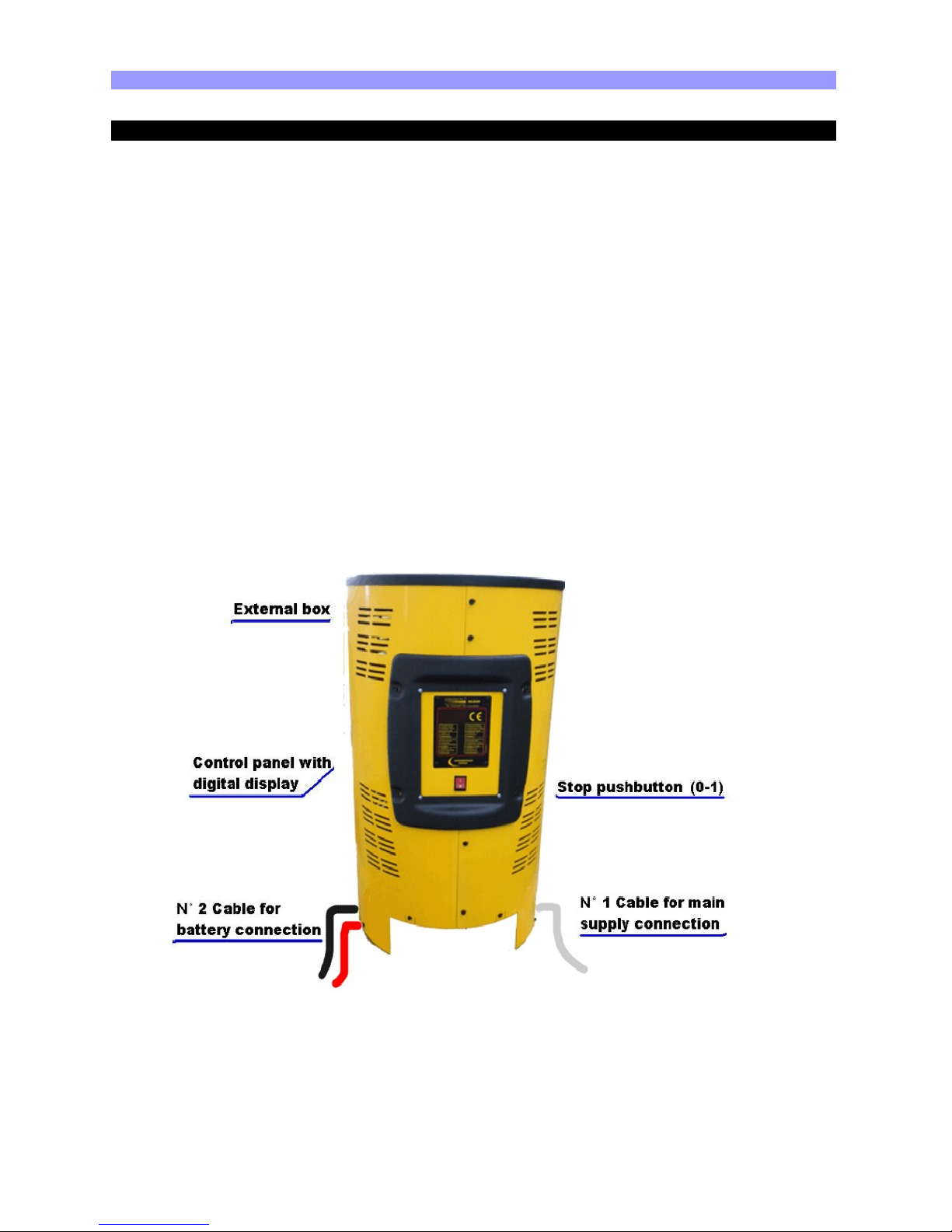
These are the principal devices included in the charger, available to the user:
• External box;
• Control panel with digital display;
• STOP pushbutton (0-1);
• No.2 Cables for battery connection;
• No.1 Cable for main supply connection;
___________________________________________ ___________________________________ ___________________________________ _________________________________
Page 6/32
ENERGIC Plus AR-TOP [V.140 – January 2011] USER'S MANUAL
___________________________________________ ___________________________________ ___________________________________ __________________________________
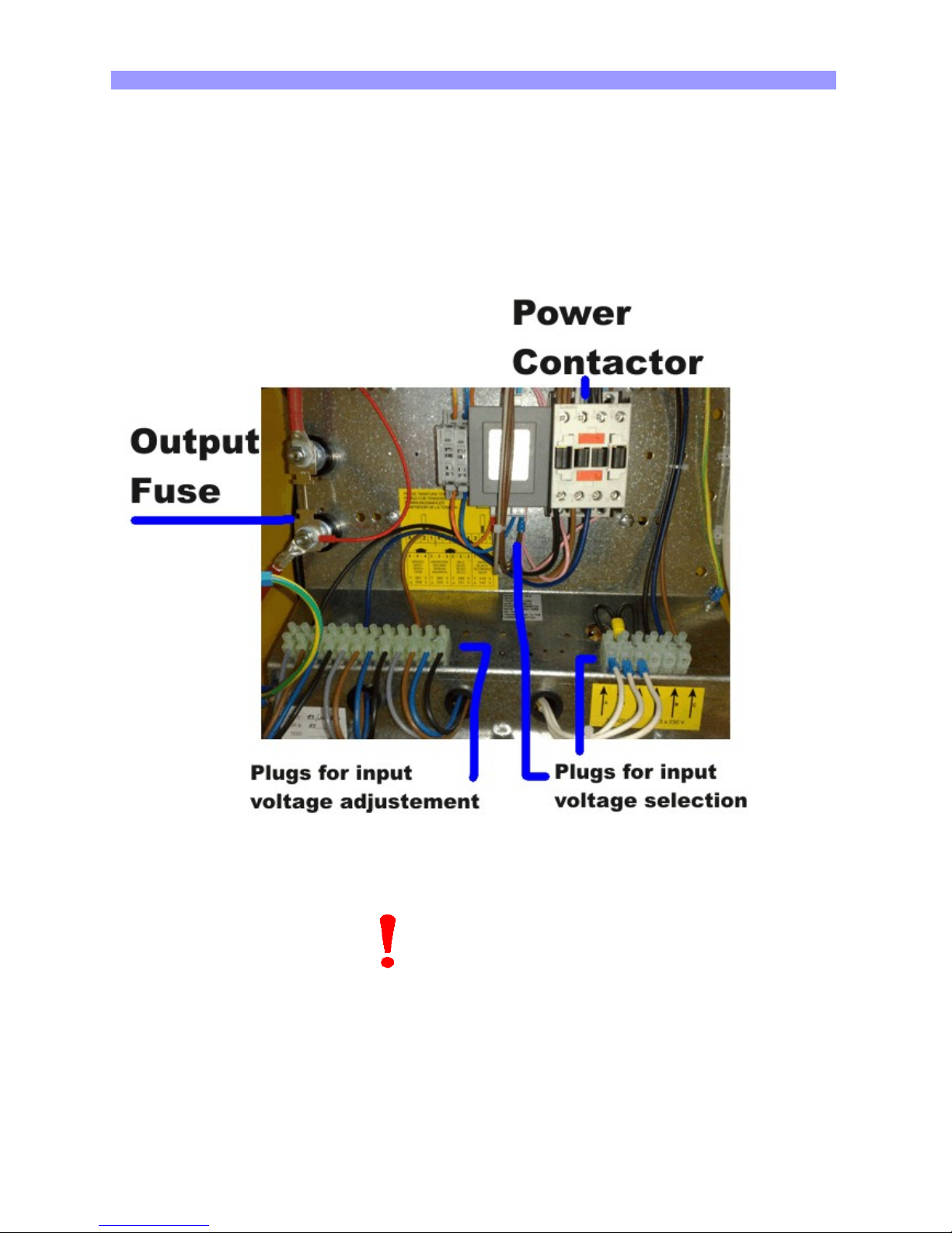
Inside of the charger, there are the following devices, not available to the user:
• Power contactor;
• Power transformer;
• Microprocessor controlled electronic board;
• Output fuse;
• Plugs for input voltage selection;
• Plugs for input voltage adjustment.
___________________________________________ ___________________________________ ___________________________________ _________________________________
Page 7/32
NOTE
The PLUG/BOARD FOR INPUT VOLTAGE SELECTION is present only in chargers with
3x 220 / 380 Vac input, and it's NOT present in chargers with 3x440 Vac input.
The PLUGS FOR INPUT VOLTAGE ADJUSTMENT are present in all the chargers.

ENERGIC Plus AR-TOP [V.140 – January 2011] USER'S MANUAL
___________________________________________ ___________________________________ ___________________________________ __________________________________
The charger is marked with a technical label, containing the following data:
• Model;
• Serial number (S/N);
• Weight (kg and lbs);
• Input voltages (V);
• Maximum input current (A);
• Maximum input power (KVA);
• Input frequency (Hz);
• Battery voltage (V);
• Maximum output current (A).
___________________________________________ ___________________________________ ___________________________________ _________________________________
Page 8/32
CAUTION !
Allow adequate air circulation to prevent internal heat buildup.
Do not place the unit near materials that may block the ventilation slots.
Do not install the unit near heat sources such as radiators or air ducts, or in a place
subject to direct sunlight, excessive dust, mechanical vibration or shock.
CAUTION !
The operations and settings described in this chapter are
fundamental for the good functionality of the charger.
Improper settings can cause severe damage to the charger and the battery!
Before to install the charger:
Check that the charger input voltage (V) is identical to your AC power supply voltage.
Check that the charger max input power (KVA) is available from your AC power supply.
ENERGIC Plus AR-TOP [V.140 – January 2011] USER'S MANUAL
___________________________________________ ___________________________________ ___________________________________ __________________________________
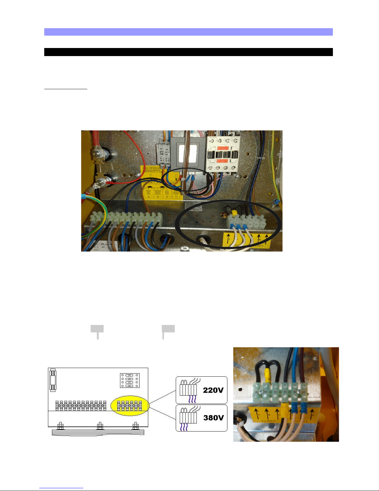
AC VOLTAGE SELECTION 3 x 220/380 V
The BOARD FOR INPUT VOLTAGE SELECTION is composed by six terminal blocks, to be
connected in one of the two configurations represented on the picture inside the charger.
PROCEDURE:
• Check that the charger is disconnected from AC input and battery;
• Open the cabinet and move the three wires (WHITE) in position 220V or 380V;
• Close the cabinet.
STEP:1 INTERNAL AUX TRASFORMER in the middle of the picture
a) 220V 380V
14-0 14-0
_____________ _____________
| | | |
| | | |
|_____________| |__________ ___|
400-X-230-230-0 400-X-230-230-0
- GRAY WIRE
STEP:2
___________________________________________ ___________________________________ ___________________________________ _________________________________
Page 9/32

ENERGIC Plus AR-TOP [V.140 – January 2011] USER'S MANUAL
___________________________________________ ___________________________________ ___________________________________ __________________________________
AC INPUT VOLTAGE ADJUSTMENT
The local AC input voltage must be measured with an adequate voltmeter, then the charger
input must be adjusted by moving the three wires marked with the letters A, B, C on the
PLUGS FOR INPUT VOLTAGE ADJUSTMENT.
PROCEDURE:
• Check that the charger is disconnected
from AC input and battery;
• Open the cabinet and move the wires A,
B, C to the desired position.
• Close the cabinet.
___________________________________________ ___________________________________ ___________________________________ _________________________________
Page 10/32
 Loading...