


350W Drill Press
ENB540DBT
Barcode:5052931253630
Warning! Read the instructions before using the product!
Original Instructions_MNL_ENB540DBT_V02_111222


ENB540DBT by ENERGER
GB
IE
Let's
get started...
These instructions are for your safety. Please read through them
thoroughly before use and retain them for future reference.
Getting
Your product
Technical and legal information
Before you start
In
more
Product functions
Care and maintenance
Trouble shooting
Recycling and disposal
Guarantee
EC declaration of conformity
started
detail
03
04
05
12
18
19
24
28
30
31
32
03

ENB540DBT by ENERGER
GB
IE
Your product
Getting started...
12
10
Your product
13
14
15
04
1. Pulley guard
2. Motor
3. Feed handles
4. Chuck guard
5. Column
6. Support lock
7. Base
8. Table
9. Chuck
10. Machine casing
11. On/off switch
12. Drill depth gauge
13. Grub screw
14. Pulley guard cross screw
15. Belt tension lock knob


ENB540DBT by ENERGER
Safety warnings
WARNING! When using electric tools basic safety precautions should
always be ic shock and personal followed to reduce the risk of fire, electr
!
injury including the following.
Read all these instructions before attempting to operate this product
and save these instructions.
Technical and legal information
GB
IE
Safe operation
1. Keep work area clear
- Cluttered areas and benches invite injuries.
2. Consider work area environment
- Do not expose tools to rain.
- Do not use tools in damp or wet locations.
- Keep work area well lit.
- Do not use tools in the presence of flammable liquids or gases.
3. Guard against electric shock
- Avoid body contact with earthed or grounded surfaces (e.g. pipes, radiators,
ranges, refrigerators).
4. Keep other persons away
- Do not let persons, especially children, not involved in the work touch the tool
or the extension cord and keep them away from the work area.
5. Store idle tools
- When not in use, tools should be stor ed in a dry locked-up place, out of reach
of children.
6. Do not force the tool
- It will do the job better and safer at the rate for which it was intended.
In more detail...
7. Use the right tool
- Do not force small tools to do the job of a heavy duty tool.
- Do not use tools for purposes not intended; for example do not use circular
saws to cut tree limbs or logs.
8. Dress properly
- Do not wear loose clothing or jewellery, they can be caught in moving parts.
- Non-skid footwear is recommended when working outdoors.
07

GB
IE
ENB540DBT by ENERGER
- Wear protective hair covering to contain long hair.
9. Use protective equipment
- Use safety glasses.
- Use face or dust mask if working operations create dust.
10.Connect dust extraction equipment
- If the tool is provided for the connection of dust extraction and collecting
equipment, ensure these are connected and properly used.
11. Do not abuse the cord
- Never yank the cord to disconnect it from the socket. Keep the cord away from
heat, oil and sharp edges.
12. Secure work
- Where possible use clamps or a vice to hold the work. It is safer than using
your hand.
13. Do not overreach
- Keep proper footing and balance at all times.
14. Maintain tools with care
- Keep cutting tools sharp and clean for better and safer performance.
In more detail...
- Follow instruction for lubricating and changing accessories.
- Inspect tool cords periodically and if damaged have them repaired by an
authorized service facility.
- Inspect extension cords periodically and replace if damaged.
- Keep handles dry, clean and free from oil and grease.
Technical and legal information
15. Disconnect tools
- When not in use, before servicing and when changing accessories such as
blades, bits and cutters, disconnect tools from the power supply.
16. Remove adjusting keys and wrenches
- Form the habit of checking to see that keys and adjusting wrenches are
removed from the tool before turning it on.
17. Avoid unintentional starting
- Ensure switch is in "off" position when plugging in.
18. Use outdoor extension leads
- When the tool is used outdoors, use only extension cords intended for outdoor
use and so marked.
08

ENB540DBT by ENERGER
19. Stay alert
- Watch what you are doing, use common sense and do not operate the tool
when you are tired.
20. Check damaged parts
- Before further use of tool, it shoul d be carefully checked to determine that it
will operate properly and perform its intended function.
- Check for alignment of moving parts, binding of moving parts, breakage of
parts, mounting and any other conditions that may affect its operation.
- A guard or other part that is damaged should be properly repaired or replaced
by an authorized service centre unless otherwise indicated in this instruction
manual.
- Have defective switches replaced by an authorized service centre.
- Do not use the tool if the switch does not turn it on and off.
21. Warning
- The use of any accessory or attachment other than one recommended in this
instruction manual may present a risk of personal injury.
22. Have your tool repaired by a qualified person
- This electric tool complies with t he relevant safety rules. Repairs should only
be carried out by qualified persons using original spare parts, otherwise this may
result in considerable danger to the user.
Technical and legal information
GB
IE
In more detail...
ADDITIONAL SAFETY RULES FOR BENCH DRILL PRESS
Warning!
!
- This machine must be firmly secured to a suitable workbench or other stable
work surface. When selecting a suitable location for mounting this machine
consideration must be given to the maximum length of the material to be drilled or
machined and the position of the operator.
- Before starting the machine ensure that drills and other recommended cutting
tools are fitted correctly and that all the securing bolts are tight. Check all
guards are fitted and operating correctly and that the chuck key and any other
adjustment tools have been removed.
- Keep hands well away from rotating drills and other cutting tools at all times.
- When drilling use the correct cutting lubricant /coolant for the material being
drilled. Use only sufficient to prevent the drill from overheating and make sure that
Ensure that power tools are disconnected from the mains supply when
not in use, making adjustments and before servicing, lubricating or
when changing accessories such as blades, bits and cutters.
09

GB
IE
ENB540DBT by ENERGER
it is kept well away from electrical components. Never use water as a coolant.
Keep drills and other cutters sharp and in good condition. This will improve cutting
and reduce the load on the machine ensuring a longer life of the cutting tools
and the machine.
- Use only drill bits, cutters and other accessories recommended by the
manufacturer. Select the correct spindle speed for the size of drill being used.
See the instruction manual. Do not attempt to modify the machine or its
accessories in any way.
- Do not force the machine, let the machine do the work. This will reduce the
wear on the machine and cutter and increase its efficiency and operating life.
- Use approved safety glasses or goggles at all times, and a face mask and ear
defenders when using for prolonged periods.
- When drilling long lengths of material ensure that there is adequate support at
both ends of the material.
Never use the machine without the safety guards in position and operating
correctly.
- When drilling wood and wood type materials, ensure that the work piece is free
from any nails or other foreign objects that could damage the drills and other
cutting tools.
In more detail...
- Always secure the workpiece in a suitable drill vice.
- Never try and secure the workpiece with your hands.
- Be aware that swarf can be very sharp and hot and can fly off the rotating drill.
When handling swarf always wear suitable gloves. Swarf should not be
disposed of with domestic waste, it should be disposed of at a recycling centre.
- Never leave the machine running while unattended. If you are interrupted when
operating the drill, complete the process and switch off before looking up.
- Always allow the machine to come to a complete stop and disconnect from the
power supply before leaving the unit unattended.
- Never use your hands to remove dust, chips or waste close by the drill bit.
Even when the tool is used as prescribed it is not possible to eliminate all residual
risk factors. The following hazards may arise in connection with the tool抯
construction and design:
- Contact with the drill bit.
- Kickback of work piece and parts of workpiece.
- Bit fracture.
Technical and legal information
10

ENB540DBT by ENERGER
- Catapulting of bit pieces.
- Damage to hearing if effective ear defenders are not worn.
- Damage to lungs if effective breathing protection is not worn in operations in
which dust is produced.
- Damage to sight if effective eye protection is not worn.
Technical and legal information
GB
IE
Wear goggles
Wear ear defenders
Wear a breathing mask
In more detail...
11

ENB540DBT by ENERGER
Before you start
GB
IE
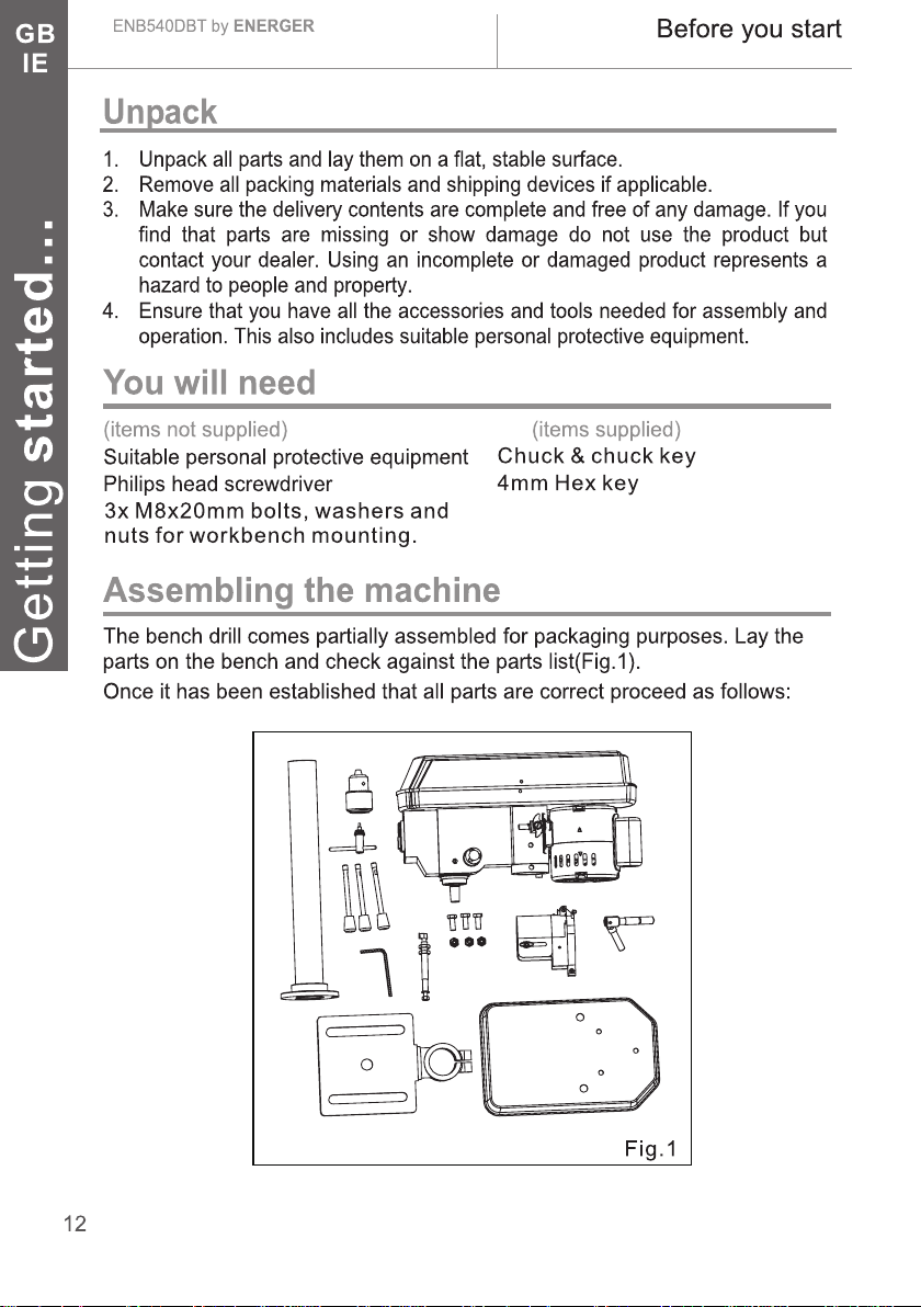
Mounting the base plate
Select a suitable location for the drill on a
workbench. Be aware of table legs and
anything which might reduce access to
the underneath of the workbench. A suitable
mains supply socket must also be accessible
for the plug. Locate the base plate(7) in the
selected position. Select two suitable length
bolts, washers and nuts (not supplied).
Using the base plate as a template drill (7)
two holes through the workbench.Bolt
the base plate to the bench. Do not over (7)
tighten as this could crack the cast base plate . (Fig.2)
7
Fig.2
Fitting the column
Align the three threaded holes on the
base plate(7) with the column(5) support holes.
Secure with the three bolts.
Do not over tighten as this could crack the cast
base plate(7) and column(5)
support(Fig.3).
5
Getting started...
Fig.3
Fitting the table
Lower the table assembly onto the column(5). The
assembly will slide easily into position so do not use
force. Make sure the table assembly will rotate 360
Tighten the support lock to secure the table assembly
into position . (Fig.4)
O
8
6
5
Fig.4
13
GB
IE
ENB540DBT by ENERGER
Before you start
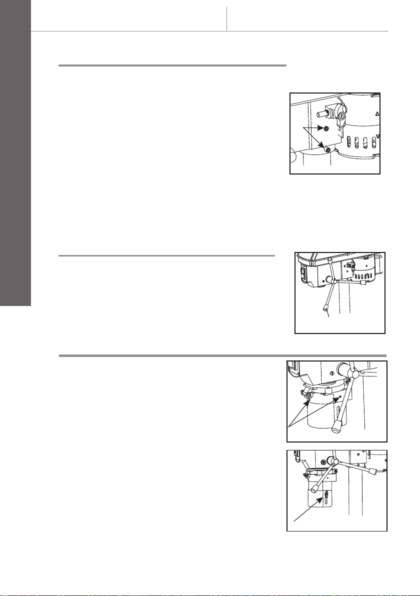
Fitting the head stock and motor
Locate the two grub screws in the side of the
head stock and motor assembly. Using a
hexagonal key slacken the two grub screws.
Lift the head stock and motor assembly and
lower it onto the column(. Make sure that it
slides down and locates fully on the column.
Position the head stock and motor assembly
ensuring it is aligned with the base plate(7).
Tighten the two grub screws to secure the
head stock and motor assembly into place(Fig.5).
Retain the hexagonal keys for future adjustments.
13
Fig.5
Fitting the hand feed handles
Locate and install the three hand feed handles(3).
Simply screw the handles into the three (3)
Getting started...
threaded holes located in the feed shaft boss.
Make sure that all three handles are tight . (3) (Fig.6)
3
Fig.6
Fitting the chuck guard
Warning:never attempt to use the machine
without the chuck guard(4) fitted.
The telescopic chuck guard is partially (4)
assembled onto the machine.
Remove three cross head screws just
below the hinge on the red collar.
Position the transparence plastic shield into the
red collar and secure in place with the three
small cross head screws . The chuck (Fig.7-1)
guard(4) is spring loaded and on a hinge which
allows the guard to be moved upwards to (4)
expose the chuck for drill installation and (9)
Fig.7-1
Fig.7-2
14

ENB540DBT by ENERGER
removal. Always return the guard(4) to cover rotating parts. Simply unscrew the
wing nuts and the two piece guard will extend vertically up or down. Chuck
guard(4) is adjustable to varying depths to give more protection(Fig.7-2).
Before you start
Fitting the drill depth gauge
Remove the red pointer and uscrew M6
Nut from the bar. Insert the bar into the
hole and the hole guard(4), located in chuck
then screw the nut, assemble the red
pointer in the spindle(Fig.8).
Fig.8
Fitting the 3 jaw chuck
This machine is supplied with a Morse taper
stub shaft fitted into the spindle. To fit the
chuck(9), clean the protective film from the
chuck internal taper and the stub shaft (9)
external taper with white spirit. Place the
chuck onto the exposed stub shaft. Place (9)
a piece of wood onto the drill table. Using the
feed handles(3) lower the chuck onto the (9)
wood.Gently apply pressure to engage the
taper and then let the spindle raise to its
upper position . (Fig.9)
9
Fig.9
GB
IE
Getting started...
The drill is now fully assembled and secured
in position. The following adjustments and
setting up instruction must be carried out
before connecting the machine to the mains
supply.
Fig.10
15

ENB540DBT by ENERGER
Check that you have noted all the following instructions:
Before starting you must have fully read and understood
the entire instruction manual.
Working with this product is demanding; therefore ensure
you are physically and mentally fit to complete the job
safely.
Ensure that you have all the accessories and tools needed
for assembly and operation.
Make sure that you wear suitable personal protective
equipment.
Ensure that no unauthorised people, especially children,
and pets are nearby or could enter the working area.
Ensure that the product is free from damage and that it is
not worn.
Safety
GB
IE
Make sure that safety devices and accessories are
correctly fixed.
Double check that all assembly tools have been removed
from the product before use.
Undertake periodic structural checks of this product; do not
WARNING! For your own and the safety of other people you must
read and follow the safety instructions in section “In more detail Technical and legal information - Safety warnings”.
use it if you have any doubts about its suitability for its
intended purpose.
17
Getting started...

ENB540DBT by ENERGER
GB
IE
In more detail
In more detail...
18
Product functions
Care and maintenance
Trouble shooting
Recycling and disposal
Guarantee
EC declaration of conformity
19
24
28
30
31
32

ENB540DBT by ENERGER
Intended use
Product functions
GB
IE
This drill press
product is used to drill holes in metal and wood.
The product should not be used on masonry and materials that are harmful to
health.
This product is intended for private domestic use only, not for any commercial
trade use. It must not be used for any purposes other than those described.
ENB540DBT
is designated with a rated input of 350 Watts. This
Adjusting the table height
To adjust the table height, slacken the (8)
support lock(6) at the rear of the table
support assembly.Raise table(8) up or down to
desired height. When the desired height has
been achieved, do not forget to re-secure the
support lock(Fig.11).
Work table swing 360
The table may also be swung through 180 either way to allow larger workpieces (8)
to be accommodated on the base plate. Simply unclamp the table and manoeuvre
either clockwise or anti-clockwise to the rear of the machine.
o
o
8
6
Fig.11
Tilting the table ± 45°
In more detail...
Locate the securing bolt underneath the
table(8). With a suitable socket loosen the bolt.
On the table support assembly casting there
is a graduated 0 - 45 scale. Set the table to (8)
the required angle and retighten the bolt.
Note: The graduated scale is for guidance
only we recommend the use of an engineers
protractor when setting any angles.
o
Fig.12
19

GB
IE
ENB540DBT by ENERGER
Product functions
Using a machine vice(vice not supplied)
WARNING: The drill should never be used
without the work piece being securely held in
a machine vice or clamped directly to the drill
table . The drill table is designed to accept a (8) (8)
variety of machine vice which can be fastened
directly to the drill table . Always secure the (8)
vice to the table with bolts, washers and nuts. (8)
If the drill jams into the work piece an
unsecured machine vice will spin out of
control causing the drill to snap and possibly
injure the operator . (Fig.13)
Fig.13
Using the 3 jaw chuck
Select the drill bit required. Open the jaws and
insert the drill shank centrally into the chuck(9).
Rotate the chuck by hand until the jaws (9) grip
the drill bit. The chuck has three holes (9)
around the chuck body. Locate the chuck key
In more detail...
and using an even torque move from each
hole location until all three holes have been
covered. Continue with the steady torque
until tight. Do not over tighten otherwise you
will have difficulty removing the drill bit . (Fig.14)
Fig.14
Note: remove the chuck key before use.
Different drill bits and chisels can be used with this product depending
on the workpiece material and application required.
WARNING! Always use drill bits according to the intended use!
For example, never use a drill bit intended for working on wood for
working on stone or vice versa!
Observe the technical requirements of this product (see section
“Technical specifications") when purchasing and using drill bits!
Some drill bits are very sharp and become hot during use!
Handle them carefully! Wear safety gloves when handling drill bits in
order to avoid injuries like burns and cuts!
20


GB
IE
ENB540DBT by ENERGER
Drill speed chart
Belt setting Spindle speed (min-1)
1 500
2 890
3 1400
4 1900
5 2500
Slacken the belt tension locking knob. This will
allow the tension on the drive belt to be
released. The motor assembly is hinged to
allow tensioning of the drive belt. To move the
drive belt to the desired pulley arrangement
push the belt on the largest drive spindle pulley
towards the next smallest pulley and at the
same time rotate the drive spindle, by hand
until the drive belt locates onto the next
smallest pulley. Repeat this procedure on the
motor pulley until the desired pulley
In more detail...
arrangement has been achieved( . Fig.18)
NOTE: Do not cross the belt to give
intermediate speeds this will cause damage to
the machine.
Product functions
15
Fig.18
Belt tension
When the desired pulley arrangement has
been achieved tension the drive belt. To check
that the correct tension has been achieved,
press your finger onto the centre of the drive
belt. The drive belt should move approximately
13mm.
Re-tighten the belt tension locking knob( . Fig.19)
Fig.19
General guidelines for drilling
Always centre punch the position for drilling. A centre punch is a pointed tool that
marks the material to be drilled with a small indent. It stops the drill bit moving
from the desired position.
Always start by drilling a small pilot hole and gradually progress in drill diameter.
When drilling metal, lubricate the drill tip with oil.
22

ENB540DBT by ENERGER
NEVER cool with water or water based lubricant otherwise an electric shock
could or brass. Care should be occur. DO NOT use oil when drilling copper
taken when drilling copper and brass as the drill bit will be prone to jamming.
Small diameter drills require a higher speed and as the drill diameter increases
the slower the speed required.
The following drilling speed chart is a guide only and only covers the more
common materials, drill diameters and speeds.
Product functions
Drill speed chart
GB
IE
Duty cycle(S2)
This product has a rated duty cycle of S2. This product must only be run
continuously for a maximum of 15 minutes. It must be then switched off and
allowed to cool down to room temperature before being run again for 15 minutes.
Drilling speed chart (guide only )
Material to be drilled
Drill dia
mm
3 2500
4 2500
5 1900
6 1900
7 1400
8 1400
9 890
10
11
12
13
Steel Cast iron Gun metal Aluminium Plastics Wood
890
500
500
500
2500
2500 2500 2500 2500 2500
2500 2500 2500 2500 2500
2500 2500 2500 2500 2500
1900 2500 2500 2500 2500
1900 2500 2500 2500 2500
1400 1900 2500 2500 2500
1400 1900 1900 2500 2500
890 1400 1900 1900 2500
890 1400 1400 1900 1900
500 890 1400 1400 1900
Drill speed (min-1)
2500
2500
2500
2500
In more detail...
23

GB
IE
ENB540DBT by ENERGER
The golden rules for care
In more detail...
WARNING! Always switch the product off, disconnect it from power
supply and let the product cool down before performing inspection,
maintenance and cleaning work!
WARNING! Only perform repairs and maintenance work according to
these instructions! All further works must be performed by a qualified
specialist!
NOTE: Do not use chemical, alkaline, abrasive or other aggressive
i
detergents or disinfectants to clean this product as they might be
harmful to its surfaces.
Always wear sturdy gloves when handling or changing bits and cutters as they can
be very sharp.
Keep the tools air vents unclogged and clean at all times.
Regually check to see if any dust or foreign matter has entered the grills near the
motor and around the switch. Use a soft brush to remove any accumulated dust.
Wear safety glasses to protect your eyes whilst cleaning.
Re-lubricate all moving parts at regular intervals.
Clean the product with a dry cloth. Use a brush for areas that are hard to reach.
The drill requires very little maintenance apart from keeping all unpainted
surfaces coated in light oil. Keep the machine clear of swarf which should be
disposed of in a proper manner and not put into household refuse bins.
Always inspect and check the set up and adjustments before using the machine.
Care and maintenance
CAUTION:Water must never come into contact with the tool.
Quill spring adjustment
WARNING: The quill spring is under extreme
tension.The quill spring is located in a metal
housing on the opposite side of the feed shaft
boss and returns the spindle to its upper most
position( . Fig.20)
Fig.20
Adjustment is normally only required after many hours of use when it fails to
return the spindle to its uppermost position. With the spindle in its uppermost
position. It can be seen that the metal cover has a total of three notches cut into
24

ENB540DBT by ENERGER
the edge that align with the cast body of the head stock. One of these notches is
located on to a cast peg that is part of the main casting.
WARNING: Before slackening the lock nuts ensure that the metal housing
is held ip or wrench. If not held securely the quill securely with a suitable gr
!
spring will fully uncoil.
Eye protection must be worn.Carefully slacken the lock nuts only enough to allow
the chrome housing to be pulled out far enough to just clear the cast peg while
holding the metal cover with suitable grips. The spring is still under tension and
will try to uncoil as soon as it is released so be sure to resist the torque. As soon
as the chrome housing is able to clear the cast peg, turn the chrome housing in
an anti-clockwise direction until the next notch locates onto the peg. While holding
the metal housing in this position tighten the lock nuts. Do not over tighten
otherwise you will damage the metal cover.
Care and maintenance
Spindle play
Locate the spindle play adjustment set
screw. Loosen the lock nut and finger tighten
the grub screw. Hold the grub screw into
position with a hex key and tighten the lock
nut( . Fig.21)
GB
IE
In more detail...
General inspection
Regularly check that all the fixing screws are
tight. They may vibrate loose over time.
If the supply cord requires replacing, the task
must be carried out by the manufacturer, the
manufacturers agent, or an authorised service
centre to avoid a safety hazard( .Fig.22)
Fig.21
Fig.22
Power cord
If the power cord is damaged, it must be replaced by the manufacturer, its service
agent or similarly qualified persons in order to avoid a safety hazard.
WARNING! Check the voltage! The voltage must comply with the
!
information on the rating label!
25

GB
IE
ENB540DBT by ENERGER
In more detail...
Care and maintenance
26
13
Blue

ENB540DBT by ENERGER
Repair
This product does not contain any parts that can be repaired by the consumer.
Contact a qualified specialist to have it checked and repaired.
Care and maintenance
Storage
1. Clean the product as described above.
GB
IE
2. Store the product and its access
3. Always store the product in a place that is inaccessible to children. The ideal
storage temperature is between 10 and 30 C.
4. We recommend using the original package for storage or covering the
product with a suitable cloth to protect it against dust.
o ries in a dry, frost-free place.
o
C
o
Transportation
1. Switch the product off and disconnect it from power supply before
transporting it anywhere.
2. Attach transportation guards, if applicable.
3. The product is heavy. Always carry supporting the motor, column and base plate.
4. Protect the product from any heavy impact or strong vibrations which may
occur during transportation in vehicles.
5. Secure the product t o prevent it from slipping or falling over.
In more detail...
27
GB
IE
ENB540DBT by ENERGER
Trouble shooting
Trouble shooting
Suspected malfunctions are often due to causes that the users can fix themselves.
Therefore check the product using this section. In most cases the problem can be
solved quickly.
WARNING! Only perform the steps described within these
instructions! All further inspection, maintenance and repair work
!
Problem Possible cause Solution
must be performed by an authorised service centre or a similarly
qualified specialist if you cannot solve the problem yourself!
1.Noisy
operation
In more detail...
2.Drill bit gets
excessively
hot
3.Wood
splinters on
underside
4. Drill bit
binds
5. Excessive
drill bit runout
or wobble
28
1.1 Incorrect belt tension
1.2 loose spindle pulley
1.3 loose motor pulley
2.1 Incorrect speed
2.2 Chips not coming out
of hole
2.3 Dull drill bit
2.4 Feeding too slow
2.5 Drill bit not being allowed
to cool down or not lubricated
in use
3. No back-up material
under workpiece
4.1 Not supported or
clamped properly
4.2 Improper belt tension
5.1 Bent drill bit
5.2 Worn spindle bearing
5.3 Chuck not properly
installed
1.1 Adjust tension
1.2 Tighten the pulley insert nut
1.3 Tighten the screws
2.1 Adjust the speed
2.2 Retract drill bit frequently to
clear chips
2.3 Resharpen drill bit
2.4 Feed fast enough, allow drill bit
to cut
2.5 Lubricate drill bit when cutting.
Follow S2 duty cycle time.
3. Use back-up material
4.1 Support workpiece or clamp
workpiece
4.2 Adjust tension
5.1 Change drill bit
5.2 Change bearing
5.3 Install chuck properly

ENB540DBT by ENERGER
Problem Possible cause Solution
Trouble shooting
GB
IE
6. Quill returns
too s ow or l
too fast
7.Chuck falls
when attached
to spindle, falls
off when trying
to install it
8.Pulley
sliding
off
6.Spring has improper
tension
7. Dirty, grease, or oil on
the tapered inside surface
of chuck or on the
spindles tapered surface.
8. Belt is not tight 8. Tighten the belt
6. Adjust spring tension
7. Clean it
In more detail...
29

GB
IE
ENB540DBT by ENERGER
Recycling and disposal
Waste electrical products should not be disposed of with household waste.
Please recycle where facilities exist. Check with your local authority or local
store for recycling advice.
Recycling and disposal
In more detail...
30

ENB540DBT by ENERGER
Guarantee
GB
IE
In more detail...
31

ENB540DBT by ENERGER
EC declaration of conformity
32

GB
Powersmith (UK) LTD.
Trade House Mead Avenue, BA22 8RT
 Loading...