

Page 1

1470 Don Street • Naples, Florida 34104 Telephone: (239) 643-1711
Fax: (239) 643-6081
Customer Service: (800) 944-1711
2007 Installation & Operation Manual for Energenics
Air-Flow
Optimizer
Table of Contents Pa ge 1
Receiving and Installation Pag e 2
Description and Installation of Air-Flow Opti mizer Page 3
Important Installation Considerations Page 4
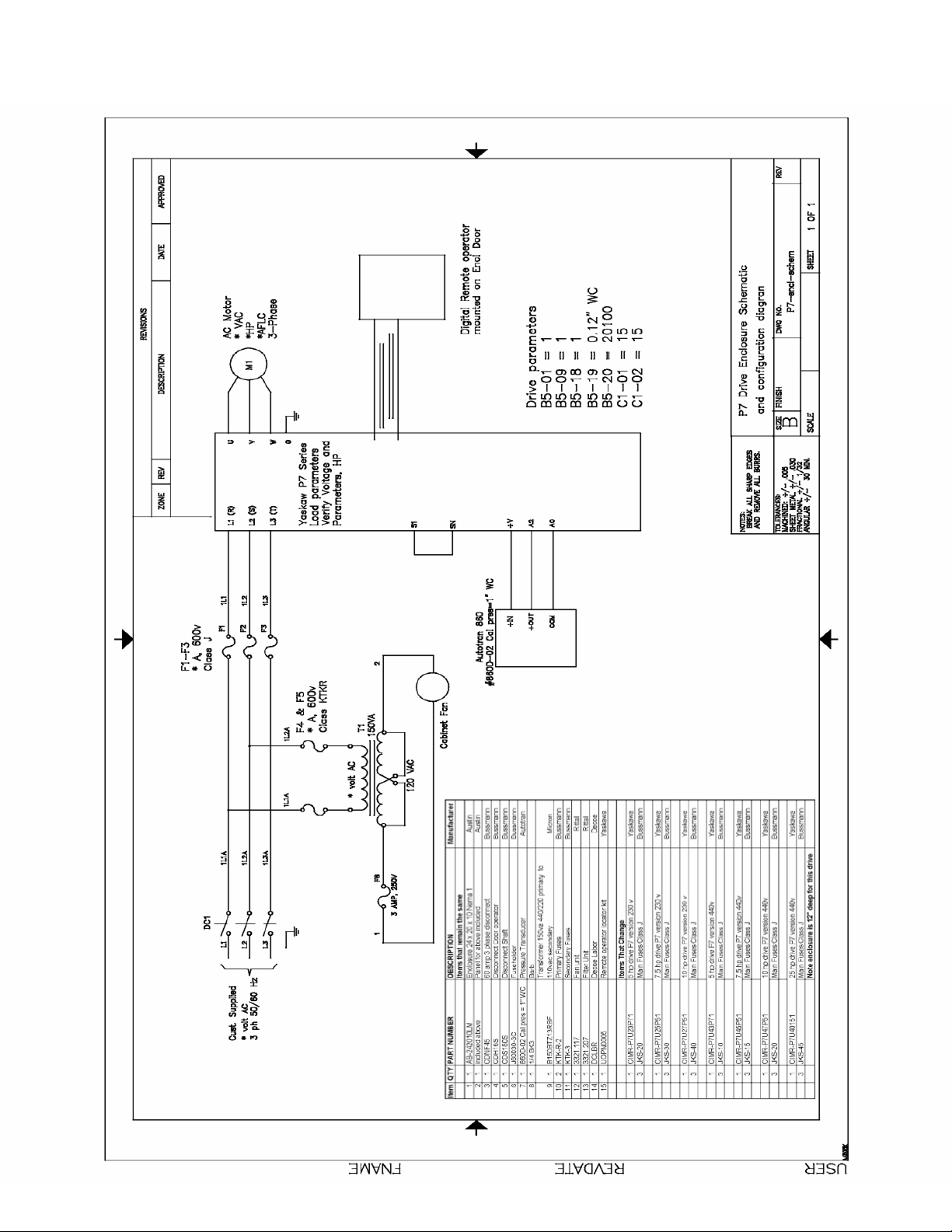
Yaskawa P7 VFD (Inverter) Wiring Diagram W/Parameters (Enclosed Box) Page 5
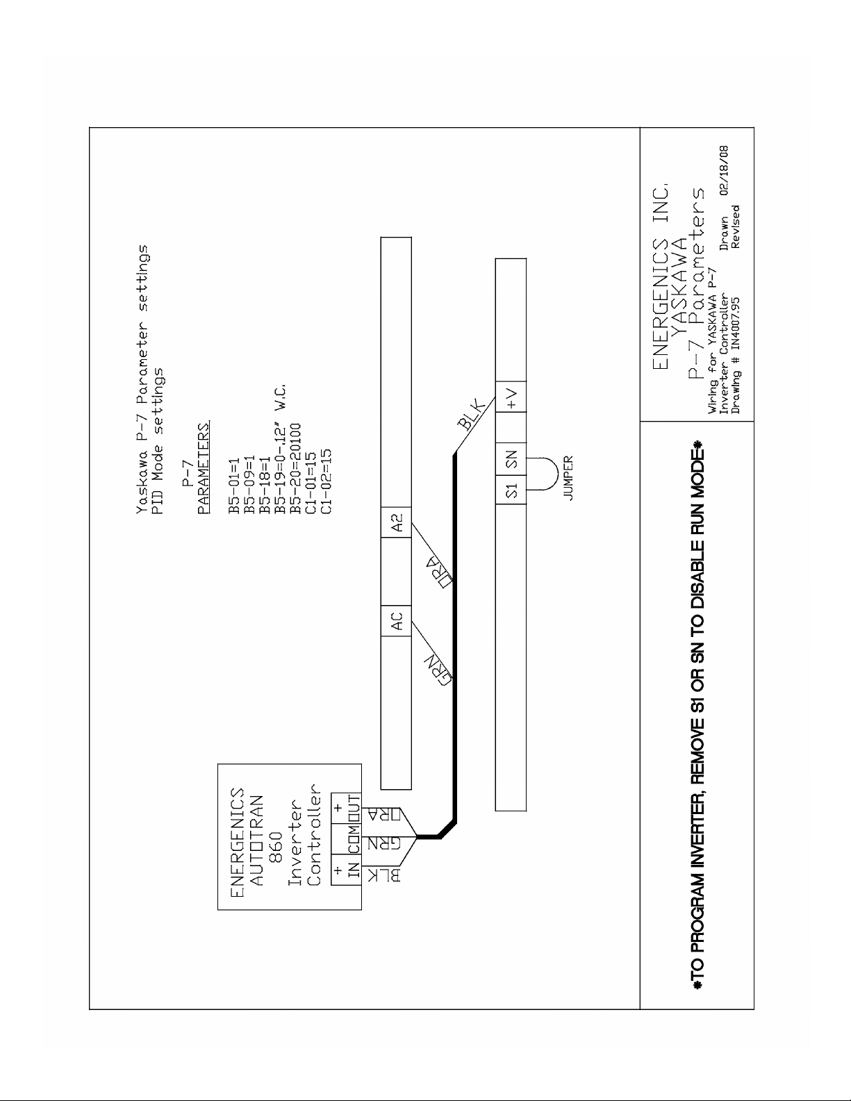
Yaskawa P7 VFD (Inverter) Wiring Diagram W/Parameters (No Enclosure) Page 6
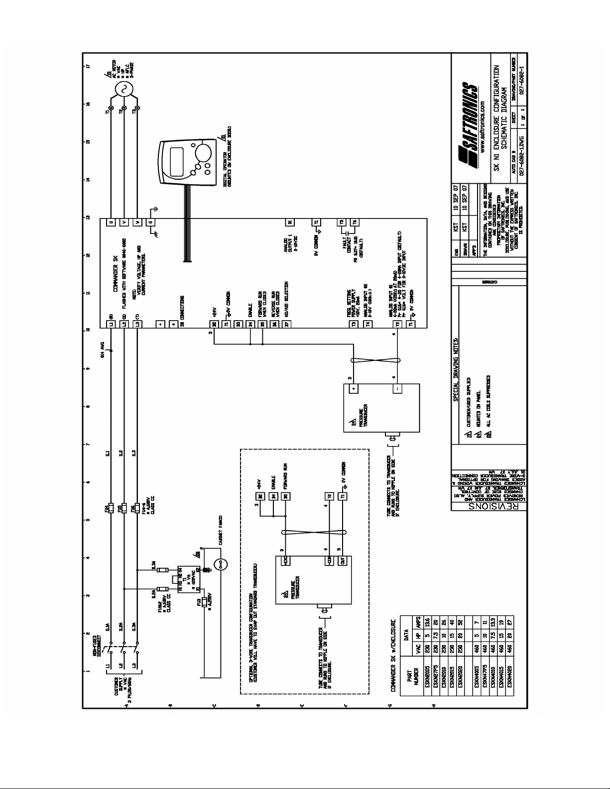
Saftronics/Emerson VFD (Inverter) Wiring Diagram (Enclosed Box) Page 7
Saftronics/Emerson VFD (Inverter) Parameters (Enclosed Box) Page 8
Saftronics/Emerson VFD (Inverter) Parameters (No Enclosure) Page 9
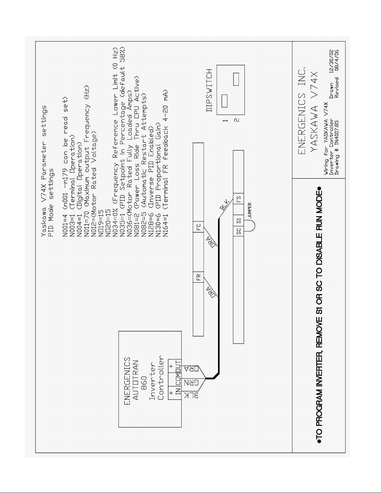
Yaskawa V74X VFD (Inverter) Parameters (No Enclosure) Page 10
Page 2

Receiving and Installation
1. Before you sign delivery documentation, ple ase inspect all packaging to
assure there is no freight damage. It is your responsibility because all
shipments are FOB Factory. Once freight is on board Energenics is
released from all liability for damage caused in transit.
2. All packaging should be kept intact in the unlikely situation where the
items have to be returned to the factory for warranty reasons. Some of
the components are manufactured by others and they stipulate that all
warranty returns must be packaged in the original materials. In t he event
that packaging is non-standard a 20% restocking fee s hall be imposed as
we will be expected to pay the manufacturer for non-compliance of their
terms.
3. After inspecting the contents the un it should be secured in a safe location
as the Air-Flow optimizer is small in size but expensive. Don’t lose it.
4. Mount the unit in a convenient location where it will be visible by plant
personnel.
Page 3

Description of Air-Flow Optimizer Operation
Your new Energenics Air-Flow Optimizer represents the most advanced feature
available in the laundry industry to date. The following is a description of its
capabilities:
The system consists of 3 components:
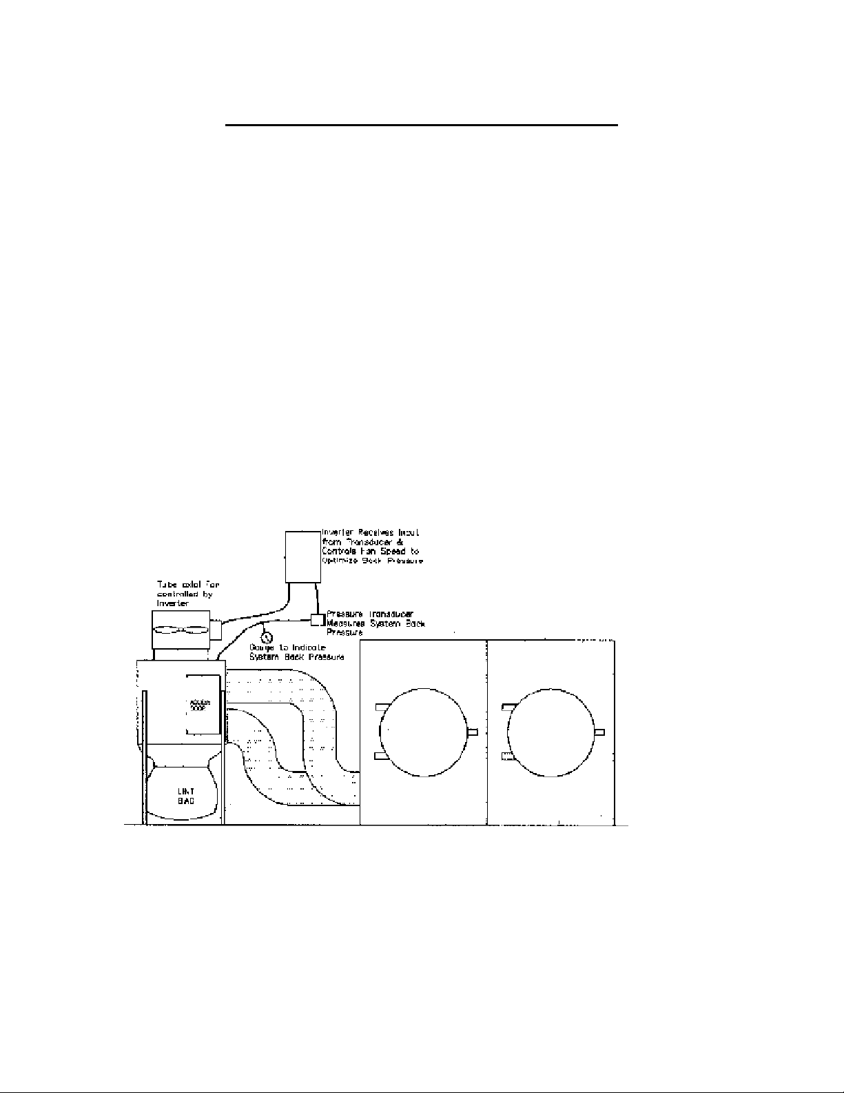
1. A pressure standoff which is to be mounted at the single point that will be
an accurate depiction of the total affect of the dryers or other devices that
result in exhaust air to be ducted outside of the laundry. A single large
exhaust manifold containing all of the dryers would be a good example.
2. The Airflow Optimizer consists of 2 components. The Pressure
Transducer and the VFD (Inverter).The Pressure Transducer should be
mounted on the same structure as the varia ble frequency drive. There is a
hose that should be connected at the pressure stand off and terminated a t
the pressure control.
3. The Variable Frequency Drive should be located in an area where it will
be readily visible to plant personnel. The drive will have a display the
percentage of Maximum Hertz (default hertz is 60) at which the fan is
being instructed to operate.
As back pressure changes due to various pieces of equip ment being on or off the
Air-Flow Optimizer will change the speed of the motor to consistently maintain a
system back pressure of .2-.4” W.C.
Page 4
Important Installation Considerations
When mounting the variable frequency drive and the Energenics pressure control
attention must be paid to with respect to the location. It is imperative that the
system be mounted in a dry relatively clean environment.
The system should receive its source of voltage from a clean dedicated circuit.
As with all solid state components they are not impervious to spikes and surges.
The system should be mounted in a visually conspicuous area that can be
observed by plant personnel. The system will display error codes if necessary
and will automatically attempt to reset on its own. In the event it does not reset it
is very important for an operator to know if there is a problem.
Page 5
Page 6
Page 7
Page 8

A
SAFTRONICS/EMERSON PARAMETERS (ENCLOSED BOX)
Parameter Comparison Listing
Project: My Project : evalentin
Drive Name: Drive (Commander SK)
Drive Mode: Open loop
Drive Address: 1
Parameter Description Default Memory Units
01.41 Analog reference 2 select OFF On
01.51 Power-up keypad reference 0 LASt
02.04 Ramp mode select Std Std.HV
02.11
05.07 Motor rated current 0.00 1.20 A
05.08 Motor rated full load rpm 1800 1700 RPM
05.14 Voltage mode select Ur I Fd
05.15 Low frequency voltage boost 3.0 1.0 %
05.34 Speed display units Fr Cd
05.50 Security unlock 0 1
06.09 Catch a spinning motor select 0 1
06.40 Enable sequencer latching OFF On
07.06 Analog input 1 mode (terminal T2) 4-.20 VoLt
07.14 Analog input 2 destination 1.37 0.00 me nu.param
08.22 Terminal B4 digital input destination 6.29 6.39 menu.param
08.23 Terminal B5 digital input destination 6.30 6.34 me nu.param
08.24 Terminal B6 digital input destination 6.32 6.31 me nu.param
11.21 Customer defined scaling 1.000 0.056
11.44 Security status L1 L3
14.03 PID reference source 0.00 18.12 menu.param
14.04 PID feedback source 0.00 1.36 me nu.param
14.05 PID reference source invert OFF On
14.06 PID feedback source invert OFF On
14.08 PID enable OFF On
14.09 Optional PID enable source 0.00 10.02 menu.pa ram
14.11 PID integral gain 0.500 0.400
14.14 PID lower limit -100.0 0.0 %
14.16 PID output destination 0.00 1.37 menu.param
18.12 Application menu 1 read-write integer 0 5000
cceleration rate 1 5.0 10.0 s/100 Hz
Page 9

SAFTRONICS/EMERSON PARAMETERS (NO ENCLOSURE)
00.03 Acceleration Time 5.0
00.04 Deceleration Time 10.0
00.06 Motor Rated current HP dependent *
00.08 Motor rated Voltage 480 or 240
00.10 Security Level L3
00.16 Analog input T2 4 to 20
00.23 Speed Display units Cd
00.24 Custom Defined Scaling 0.056
00.27 Power up keypad reference LASt
00.30 Ramp mode select STD.HV
00.39 Motor rated Frequency 60
00.32 Dynamic V to F select ON
00.33 Catch a spinning motor select 1
00.41 Voltage mode select FD
00.42 Low Frequency Voltage Boost 1.0
01.01 Minimum Speed 15
01.14 Drive Configuration A1.A2
01.15 Preset speed selector 6
01.28 Preset speed 8 5.0
01.41 Analog Reference 2 select on
05.09 Motor rated Voltage 480
06.40 Enable Sequencer Latching Off
07.10 Analog Input Destination 18.11
14.03 PID main ref. source 18.12
14.04 PID feedback source 18.11
14.05 PID ref. source invert on
14.06 PID feedback source invert on
14.08 PID Enable on
14.09 PID Enable signal 10.02
14.11 PID Integral 0.400
14.14 PID low limit 0.0
14.16 PID output Dest. 1.26
Monitor Parameters
00.81 Set Point Frequency Should read 5.0 Hz
00.85 Output Frequency Will vary with suction pressure
00.88 Output amps Should not exceed motor rated current
00.94 Analog Input 1(T2) Signal from Pressure transducer
* Motor current need to be set for proper motor thermal protection.
MT082407
Page 10
 Loading...