

Energate AW000873 Installation Manual
AW000873
Installation Guide for Energate
Thermostats
Rev Date Done By Checked
A Dec 22,
2011
B Jan 25,
2012
G. Delage S.
G. Delage S.
By
McKenzie
McKenzie
Description
Initial Release
Added information on AS20
Auxiliary Switch, dual
transformer scenarios. Added
FAQ and Troubleshooting
sections.

Table of Contents
1. Introduction ................................................................................................................................. 3
1.1 Operating the Thermostat ...................................................................................................... 3
2. Installation Procedure ................................................................................................................. 5
3. No Existing Thermostat .............................................................................................................. 6
4. Thermostat Wiring ...................................................................................................................... 7
5. Configuring the Thermostat Settings .......................................................................................... 8
6. Standard Configurations ........................................................................................................... 10
6.1 Furnace with Air Conditioner ............................................................................................. 10
6.2 Furnace with No Air Conditioner........................................................................................ 11
6.3 Air Conditioner with no furnace ......................................................................................... 12
6.4 Heat Pump - Single stage with no auxiliary stage ............................................................... 13
6.5 Heat Pump - Two stage with no auxiliary stage.................................................................. 14
6.6 Heat Pump - Single stage with auxiliary stage .................................................................... 15
6.7 Heat Pump - Two stage with auxiliary stage....................................................................... 16
7. Special Configurations .............................................................................................................. 17
7.1 No Common Wire at thermostat ......................................................................................... 17
7.2 Dual transformer scenarios.................................................................................................. 22
7.3 Zone Control Systems ......................................................................................................... 24
8. Options and Accessories ........................................................................................................... 25
8.1 Energate thermostat does not cover hole in wall (Wall Plate) ............................................ 25
8.2 Outdoor Sensor .................................................................................................................... 26
8.3 Air Filter Sensor .................................................................................................................. 26
8.4 Heat Pump Fault Sensor ...................................................................................................... 26
9. Testing the System .................................................................................................................... 27
9.1 Conventional System Test ................................................................................................... 27
9.2 Heat-Pump System Test ...................................................................................................... 28
10. Troubleshooting ...................................................................................................................... 29
10.1 Suspected installation issue ............................................................................................... 29
10.2 Return to Material Authorization (RMA) Procedure ........................................................ 31
11. Commissioning a thermostat................................................................................................... 32
12. Unsupported Configurations ................................................................................................... 33
13. Frequently Asked Questions ................................................................................................... 34
14. Energate Technical Support .................................................................................................... 37
THIS DOCUMENT CONTAINS CONFIDENTIAL INFORMATION PROPRIETARY TO ENERGATE INC. NO PART OF ITS CONTENTS MAY BE
DISCLOSED OR CONVEYED TO, USED BY, OR COPIED TO A THIRD PARTY WITHOUT PRIOR WRITTEN CONSENT BY ENERGATE INC.
2
1. Introduction
This document is intended for the use of installers who are installing Energate Z100 thermostat
(both Pioneer 1 and Pioneer 2 models).
The Energate Z100 is a 2-way communicating thermostat that supports the ZigBee Smart Energy
protocol. This document describes the typical installation scenarios and provides advice for
handling unusual situations. Section 1.1 describes how to operate the thermostat.
If you have questions that are not answered by this document, please contact Energate support as
shown in section 13.
1.1 Operating the Thermostat
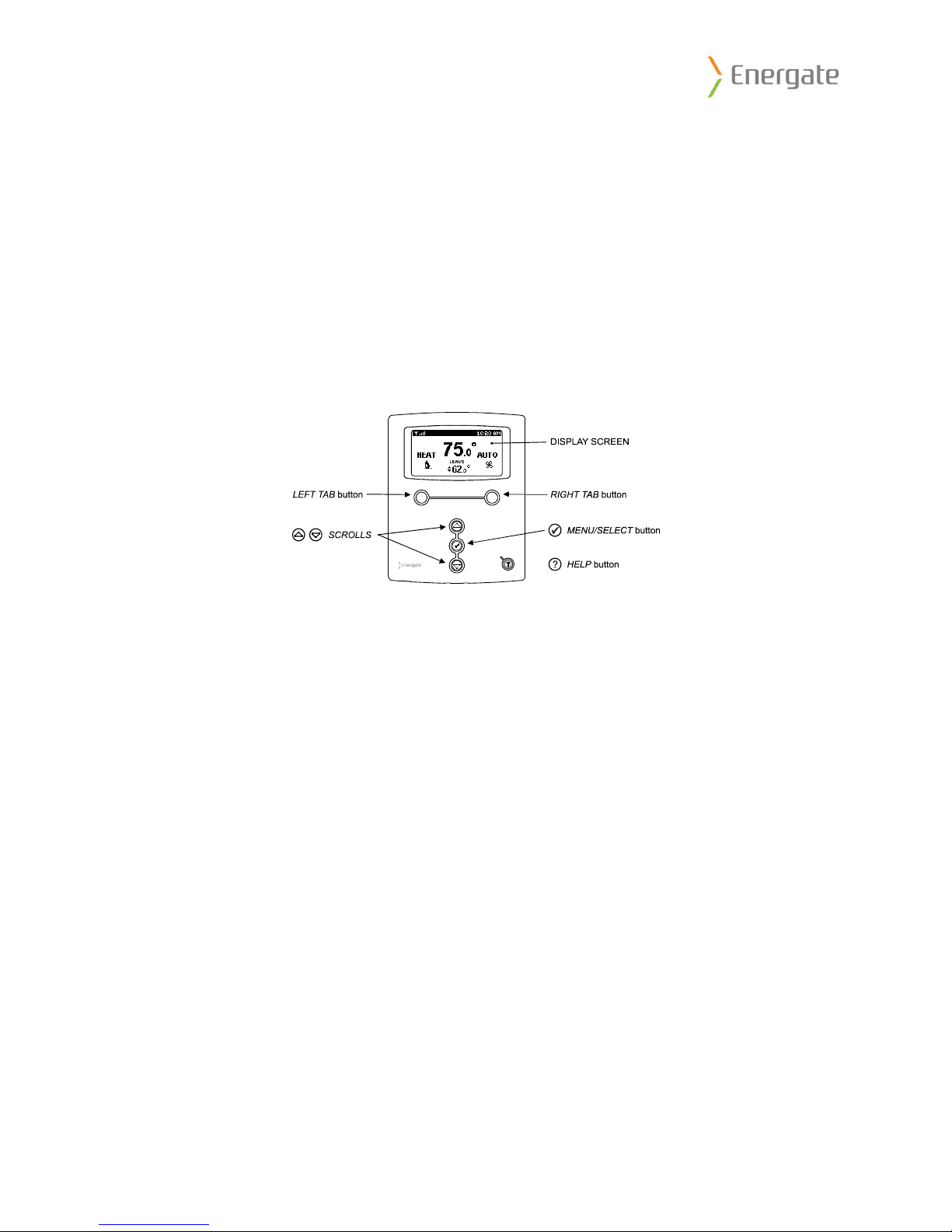
Navigating the Controls
The function of the LEFT and RIGHT TAB buttons appears on the bottom of the display screen.
Use the SCROLL (▲ ▼) buttons to adjust the temperature, move through the menus options, and
change highlighted values. Press the MENU / SELECT (√) button to access the menu as well as
to select or accept highlighted menu items.
THIS DOCUMENT CONTAINS CONFIDENTIAL INFORMATION PROPRIETARY TO ENERGATE INC. NO PART OF ITS CONTENTS MAY BE
DISCLOSED OR CONVEYED TO, USED BY, OR COPIED TO A THIRD PARTY WITHOUT PRIOR WRITTEN CONSENT BY ENERGATE INC.
3
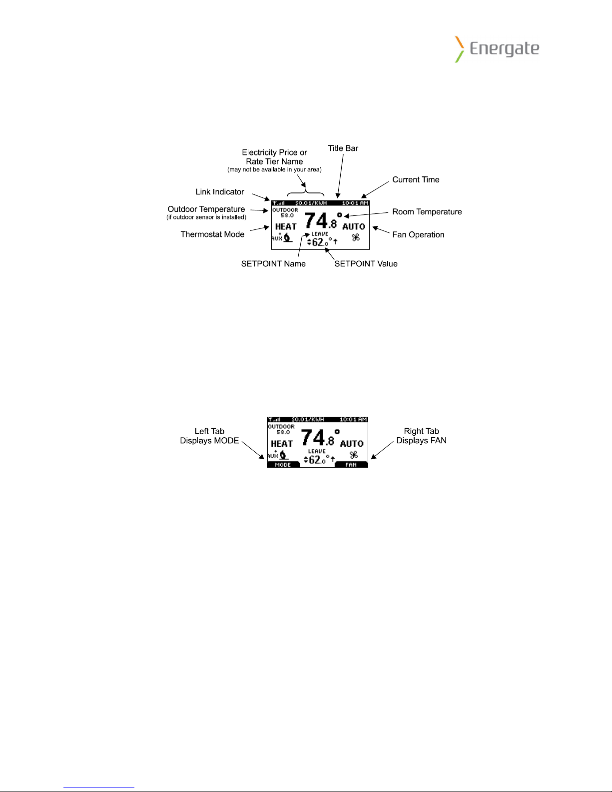
Home Screen
The Home screen displays current temperature and ope
ration data. When the Home screen is in
Idle mode, the backlight is on with low brightness. Please note that icons such as heat or fan are
animated when the equipment is running.
Note: A SETPOINT (e.g., LEAVE) is identified by a name and specifies both heating and
cooling target temperatures. See the Temperature SettingsError! No bookmark name given.
section for additional information.
By just pressing any of the buttons, the Home screen becomes Active, the backlight brightens
and the MODE and FAN tabs are shown.
Pressing the LEFT TAB button changes the thermostat mode
(COOL/HEAT/AUTO/EMERG/OFF). The available options for the thermostat mode will
depend on the type of heating or cooling equipment at your home. Pressing the RIGHT TAB
button changes the fan mode (ON/AUTO)
Pressing the SCROLL (▲ ▼) buttons makes the temperatures of the SETPOINTs higher
(warmer) or lower (cooler). You can accept the changes by pressing the LEFT TAB, which will
be displaying ACCEPT, or you can walk away after making the changes. They will be
automatically accepted when the screen goes to the Idle mode (i.e. the backlight diminishes to
low).
To see the different menu items displayed, the MENU / SELECT (√) button needs to be pressed
once when the screen is active or twice when it is in the Idle mode.
Note: Refer to the thermostat manual for complete operating instructions.
THIS DOCUMENT CONTAINS CONFIDENTIAL INFORMATION PROPRIETARY TO ENERGATE INC. NO PART OF ITS CONTENTS MAY BE
DISCLOSED OR CONVEYED TO, USED BY, OR COPIED TO A THIRD PARTY WITHOUT PRIOR WRITTEN CONSENT BY ENERGATE INC.
4

2. Installation Procedure
1. If there is no existing thermostat, please review section 3, "No Existing Thermostat" for
guidelines on mounting the thermostat and related equipment.
2. Before installing the new thermostat in the home, verify that the existing HVAC
equipment is working correctly by testing all heating and cooling stages.
3. Before disconnecting the old thermostat, record the schedule and equipment settings and
label all the wires identifying the terminals they are connected to on the old thermostat in
case it needs to be re-installed.
4. Disconnect power from the HVAC equipment, remove the old thermostat and install the
Energate Z100 thermostat as per section 6. In the event that there is no ground wire,
please review section 7.1. In the event that the thermostat backplate does not cover an
existing hole in the wall, please review section 8.1.
5. After installing the Energate Z100 thermostat, reconnect power and enter the Setup menu
to configure the thermostat for the type of equipment it is connected to as shown in
section 5.
6. Verify that all the heating and cooling stages are working correctly as shown in section 9.
7. If using an outdoor sensor, air filter sensor or heat pump fault sensor, please review
section 8.
8. If the HVAC equipment uses two transformers, please review section 7.2.
9. If the HVAC equipment is wired into a zone control system, please review section 7.3.
10. Commission the thermostat to join it to the gateway, verify the thermostat radio indicator
in the top left of the display changes from an “X” to a series of signal strength bars as
shown in section 10.
11. Show the homeowner how to use their new thermostat as per section 1.1. In particular
make sure they know how to:
a. Change the mode between Heat, Cool, Auto and Off
b. Set a temporary hold, which can also be used to override an event
c. Modify their conservation settings if the Utility is sending price information
d. Modify their schedule time and temperature settings
12. Explain how the utility program works to the homeowner.
13. Provide the homeowner with the thermostat manual and Utility documentation.
THIS DOCUMENT CONTAINS CONFIDENTIAL INFORMATION PROPRIETARY TO ENERGATE INC. NO PART OF ITS CONTENTS MAY BE
DISCLOSED OR CONVEYED TO, USED BY, OR COPIED TO A THIRD PARTY WITHOUT PRIOR WRITTEN CONSENT BY ENERGATE INC.
5
3. No Existing Thermostat
Mounting the Thermostat
Install the thermostat at 5 feet (1.5m) above the floor in an area with good air circulation at
average temperature. Avoid locations with drafts or dead spots behind doors, hot or cold air
ducts, sunlight or radiant heat from appliances, concealed pipes or chimneys and unconditioned
areas such as outside walls behind the thermostat.
The 2 wallplate anchors should be spaced 3.5 inches (90 mm) apart in a vertical direction. Pull
wires through the backplate and connect to the appropriate terminals as defined in the Wiring
Configuration.
Mounting the Outdoor Sensor
The outdoor sensor should be mounted in a shaded loc
thermostat will automatically detect the outdoor sensor and display its readings.
Cleaning the Thermostat
The thermostat can be cleaned with a soft cloth lightly dampened with isopropyl alcohol (IPA).
Excessive IPA or use of other solvents may damage the LCD!
ation, out of direct sunlight. The
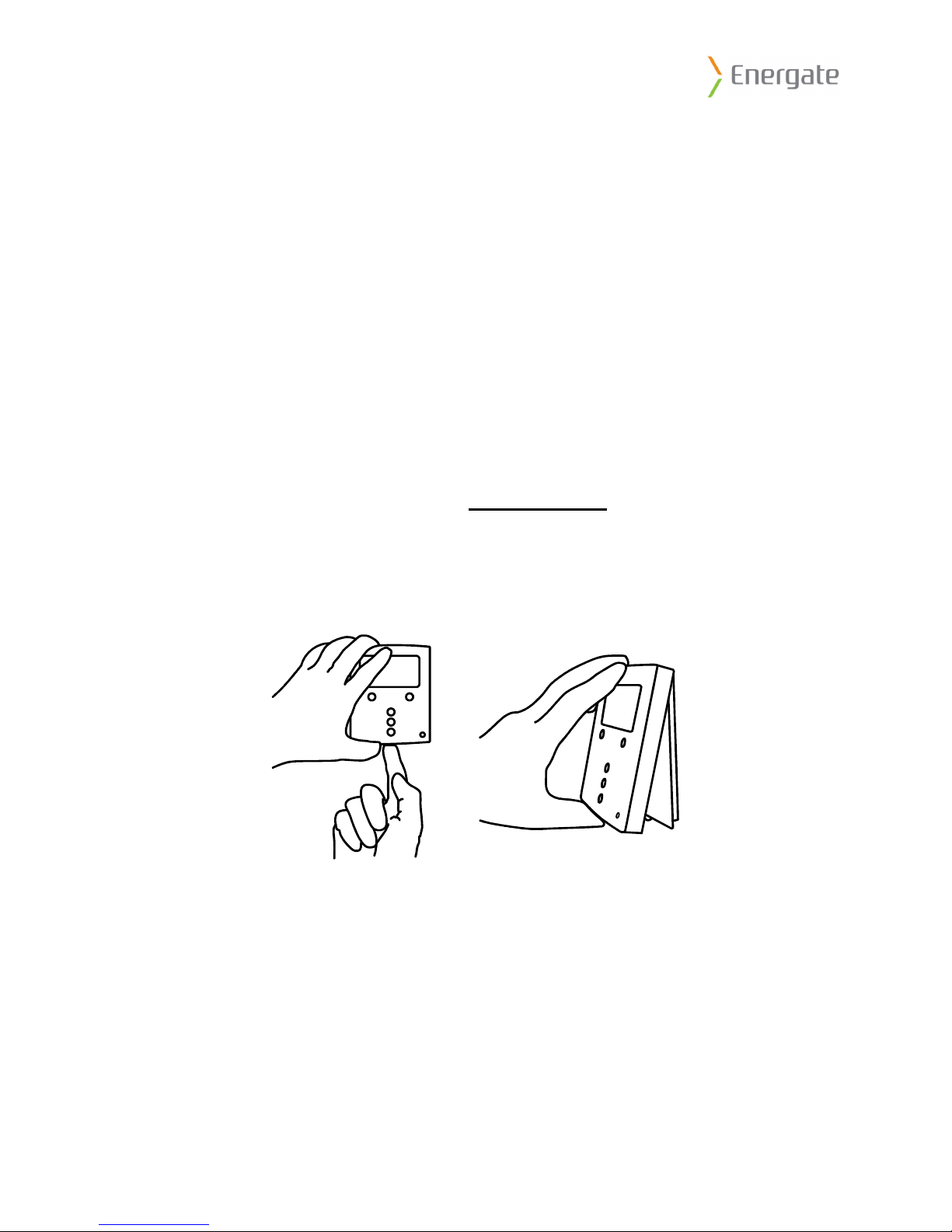
Removing Thermostat Front Housing from Backplate
To remove the thermostat front housing from the backplate, press the plastic tab located at the
bottom of the thermostat. Pull the bottom of the front housing forward and remove.
Warning: do not use metallic tools when removing battery or backplate; this may damage the
thermostat.
THIS DOCUMENT CONTAINS CONFIDENTIAL INFORMATION PROPRIETARY TO ENERGATE INC. NO PART OF ITS CONTENTS MAY BE
DISCLOSED OR CONVEYED TO, USED BY, OR COPIED TO A THIRD PARTY WITHOUT PRIOR WRITTEN CONSENT BY ENERGATE INC.
6
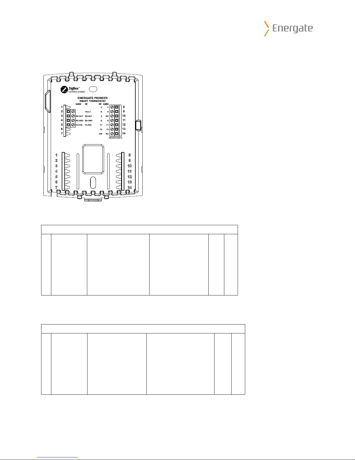
4. Thermostat Wiring
The following diagram shows the backplate of the Energate thermostat.
Conventional System
The following are the general wiring connections for a conventional system.
Conventional Systems (CONV)
1
2
3 RS OUT Outdoor Sensor
4 RS GND Sensor Ground
5 FILTER
6
7
Filter
Common(GND) C 8
Power (24VAC) R 9
1st Stage Heat W1 10
Fan G 11
1st Stage Cool Y1 12
2nd Stage Cool Y2 13
2nd Stage Heat W2 14
Heat Pump
The following are the general wiring connections for a heat pump.
Heat Pump Systems (HP)
1
2 FAULT
3 RS OUT Outdoor Sensor
4 RS GND Sensor Ground
5 FILTER
6
7
* Reversing Valve is also known as Changeover valve
Heat Pump Fault
Filter
Common (GND) C 8
Power (24VAC) R 9
Auxiliary Heat E 10
Fan G 11
1st Stage Heat Pump
2nd Stage Heat Pump
Reversing Valve*
Y1 12
Y2 13
O/B 14
THIS DOCUMENT CONTAINS CONFIDENTIAL INFORMATION PROPRIETARY TO ENERGATE INC. NO PART OF ITS CONTENTS MAY BE
DISCLOSED OR CONVEYED TO, USED BY, OR COPIED TO A THIRD PARTY WITHOUT PRIOR WRITTEN CONSENT BY ENERGATE INC.
7

5. Configuring the Thermostat Settings
In order to configure the Thermostat to match your HVAC configuration, you must use the
SETUP menu.
1. Press the Menu/Select (checkmark) button to enter the menu
2. Scroll down to the SETUP menu
3. Enter the Install Password “INST”
This will give you access to the additional menu items listed below.
Equipment Type
YPE:
• T
o Select the type of equipment (conventional or heat pump), the default is
Conventional.
• # OF COOL STAGES:
o Select the number of cool stages from 0 to 2, the default is 1.
• # OF HEAT STAGES:
o Select the number of heat stages from 0 to 2 (3 for heat pumps), the default is 1.
• REV. VALVE (for heat pumps only):
o Select whether the reversing valve is on in cool or on in heat. The default is on in
cool.
Equipment Settings
• MIN ON/OFF TIME:
o Select the minimum on/off time from 1 to 6 minutes, the default is 3.
o A minimum of 2 minutes is recommended for a furnace and 3 minutes for Heat
Pumps and Air Conditioners.
• FAN ON IN HEAT (for conventional equipment only):
o Set to yes if the thermostat controls the fan (common in electric furnaces) and no
if the furnace controls the fan (common in gas furnaces). The default is Yes.
• ALLOW HP+AUX ON (for heat pumps only):
o Set to yes if the heat pump and auxiliary heat can be on at the same time fan
(common with auxiliary electric heat).
o Set to no if the heat pump should be off when the auxiliary heat is on (common
with auxiliary fossil fuel heat).
o The default is Yes.
• BALANCE POINTS (Only for heat pumps with outdoor temperature sensor):
o HIGH: Set to the temperature above which the auxiliary heat is disabled. The
range is from -38 °F (-39 °C) to 122 °F (50 °C) and the default is 122 °F (50 °C)
and a typical value is 50 °F (10 °C).
o LOW: Set to the temperature below which the heat pump is disabled. The range
is from -40 °F (-40 °C) to 120 °F (49 °C) and the default is -40 °F (-40 °C) and a
typical value is 32 °F (0 °C).
THIS DOCUMENT CONTAINS CONFIDENTIAL INFORMATION PROPRIETARY TO ENERGATE INC. NO PART OF ITS CONTENTS MAY BE
DISCLOSED OR CONVEYED TO, USED BY, OR COPIED TO A THIRD PARTY WITHOUT PRIOR WRITTEN CONSENT BY ENERGATE INC.
8

Control
• HYSTERISIS
o Select the number of degrees the temperature must go beyond a setpoint prior to
changing from HEAT to COOL mode or vice versa when in AUTO mode. The
range is 0 °F (0 °C) to 6 °F (3 °C) and the default is 2 °F (1 °C).
• ANTICIPATION TIME
o Select the amount of time the thermostat will engage the equipment to reach the
setpoint temperature before the scheduled setpoint time. The range is from 0 to
180 minutes and the default is 60 minutes.
• MAX RECOVERY TIME (for multiple stage equipment):
o Select the amount of time the thermostat will allow the equipment to reach the
desired temperature in the current stage before engaging the next stage of heating
or cooling. The range is 0 to 180 minutes and the default is 90 minutes.
THIS DOCUMENT CONTAINS CONFIDENTIAL INFORMATION PROPRIETARY TO ENERGATE INC. NO PART OF ITS CONTENTS MAY BE
DISCLOSED OR CONVEYED TO, USED BY, OR COPIED TO A THIRD PARTY WITHOUT PRIOR WRITTEN CONSENT BY ENERGATE INC.
9
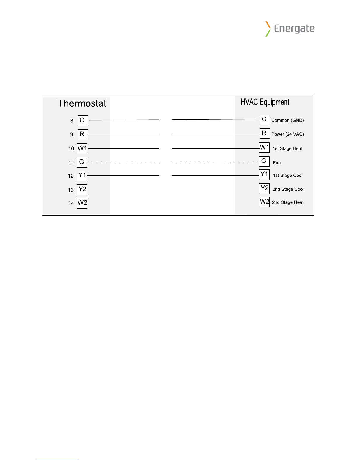
6. Standard Configurations
6.1 Furnace with Air Conditioner
Equipment Wiring
Thermostat Settings
Equipment Type
YPE: Conventional
• T
• # OF COOL STAGES: 1 for single stage air conditioner, 2 for two stage air conditioner
• # OF HEAT STAGES: 1 for single stage furnace, 2 for two stage furnace.
Equipment Settings
• FAN ON IN HEAT: Set to yes if the thermostat controls the fan (common in electric
furnaces) and no if the furnace controls the fan (common in gas furnaces).
THIS DOCUMENT CONTAINS CONFIDENTIAL INFORMATION PROPRIETARY TO ENERGATE INC. NO PART OF ITS CONTENTS MAY BE
DISCLOSED OR CONVEYED TO, USED BY, OR COPIED TO A THIRD PARTY WITHOUT PRIOR WRITTEN CONSENT BY ENERGATE INC.
10
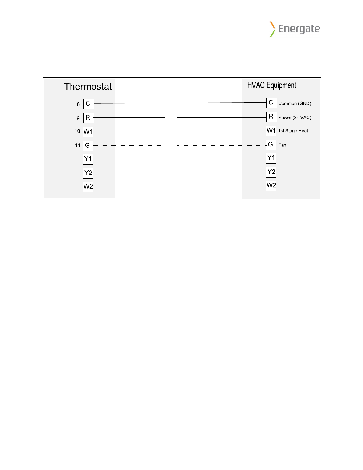
6.2 Furnace with No Air Conditioner
Equipment Wiring
Thermostat Settings
Equipment Type
• TYPE: Conventional
• # OF COOL STAGES: 0
• # OF HEAT STAGES: 1 for single stage furnace, 2 for two stage furnace.
Equipment Settings
AN ON IN HEAT: Set to yes if the thermostat controls the fan (common in electric
• F
furnaces) and no if the furnace controls the fan (common in gas furnaces).
THIS DOCUMENT CONTAINS CONFIDENTIAL INFORMATION PROPRIETARY TO ENERGATE INC. NO PART OF ITS CONTENTS MAY BE
DISCLOSED OR CONVEYED TO, USED BY, OR COPIED TO A THIRD PARTY WITHOUT PRIOR WRITTEN CONSENT BY ENERGATE INC.
11
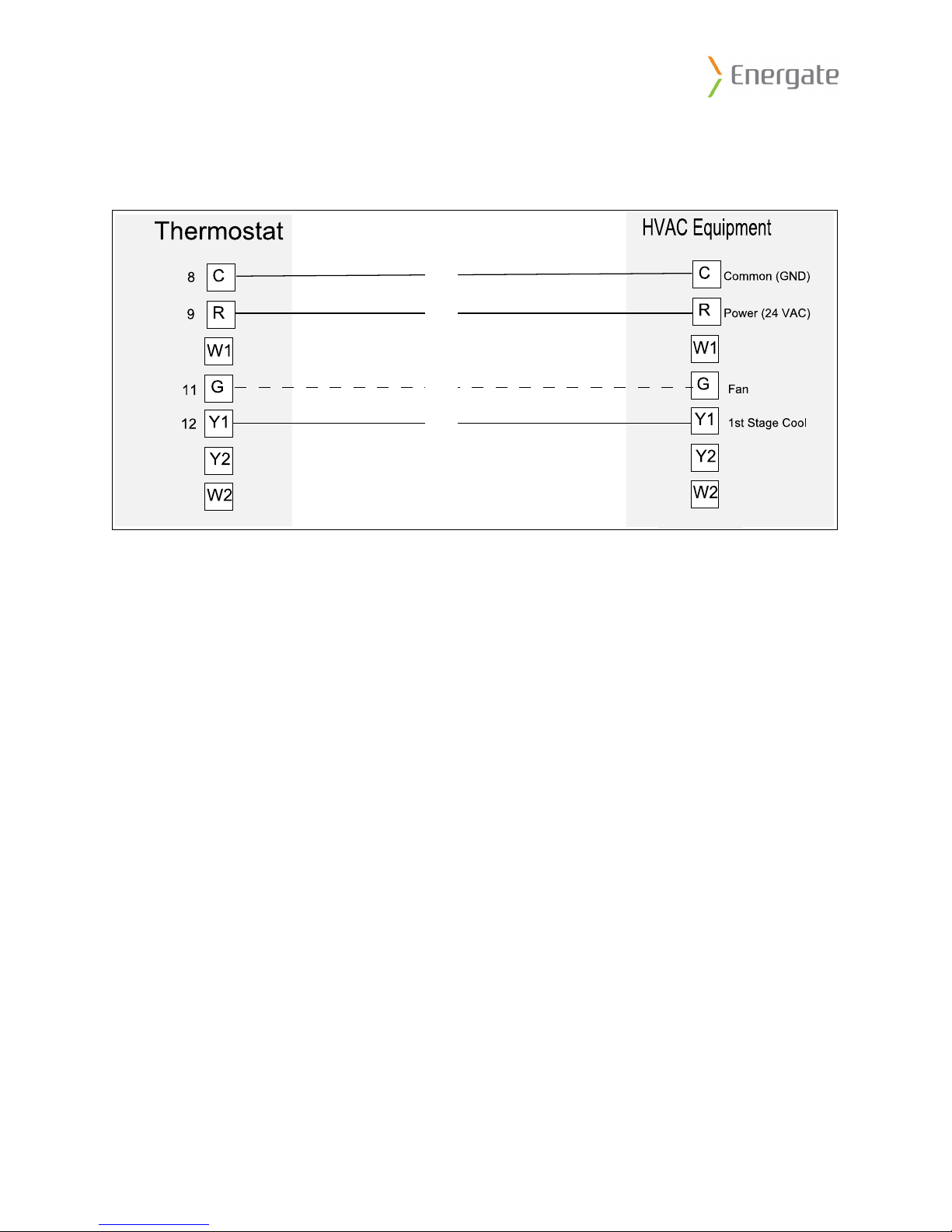
6.3 Air Conditioner with no furnace
Equipment Wiring
Thermostat Settings
Equipment Type
• TYPE: Conventional
• # OF COOL STAGES: 1 for single stage air conditioner, 2 for two stage air conditioner
• # OF HEAT STAGES: 0
THIS DOCUMENT CONTAINS CONFIDENTIAL INFORMATION PROPRIETARY TO ENERGATE INC. NO PART OF ITS CONTENTS MAY BE
DISCLOSED OR CONVEYED TO, USED BY, OR COPIED TO A THIRD PARTY WITHOUT PRIOR WRITTEN CONSENT BY ENERGATE INC.
12
 Loading...