

Enerdis Enerium 100, Enerium 200, Enerium 300, Enerium 110, Enerium 210 Installation Manual
...Page 1
MMSS11--77339988 // 001
1
Page 1 / 2
INSTALLATION
MANUAL
Enerium 100 – 200 – 300
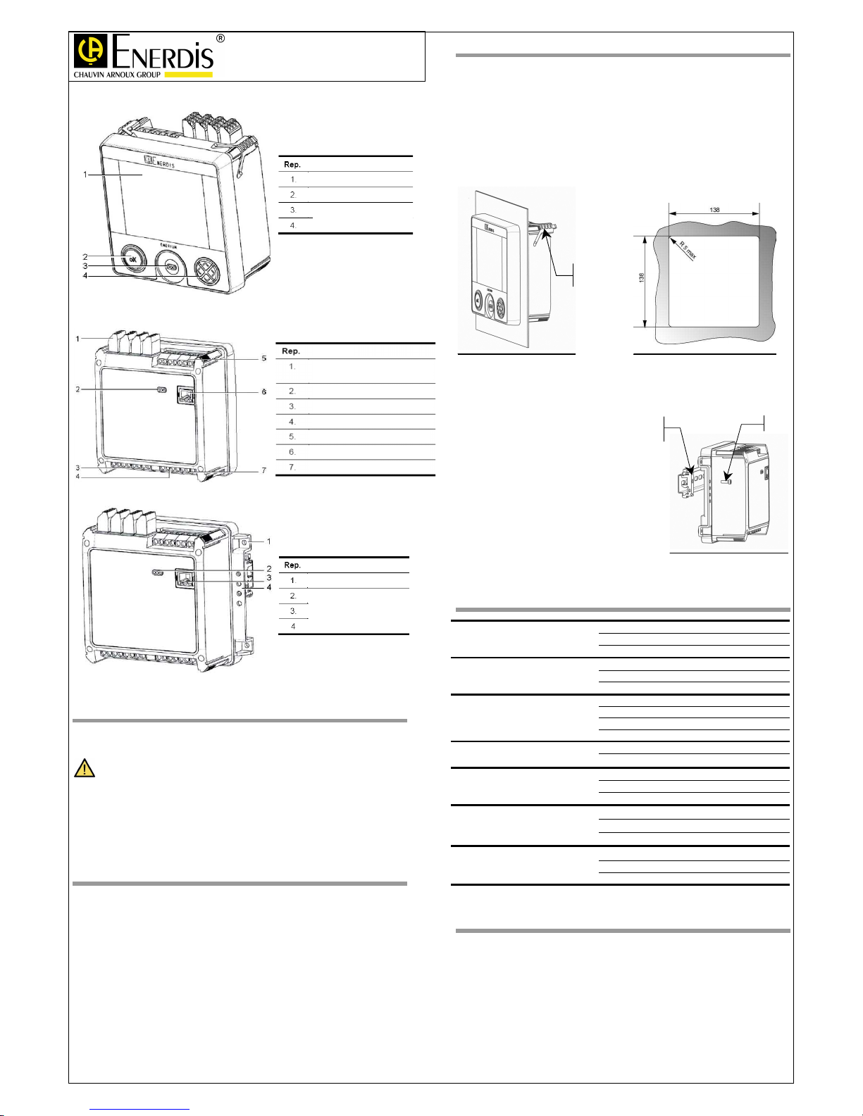
LCD Screen
Validation Key « OK »
Optical head interface
Navigation key
Function
On-off or Analogue input / output
Optical head interface
Current inputs
Voltage inputs
RS485 communication interface
Ethernet communication connection
Power supply
Function
Enerium 100
– 200 – 300
Enerium 110 – 210 – 310
Hole for fastening on grating
Optical head interface
Remote communication interface
DIN rail mounting accessory
Function
S
AFETY
You have received a power monitor ENERIUM 100, 110, 200, 210, 300 or
310 and we thank you for your confidence.
To install this device with best conditions:
• Read this manual and the user’s manual MS1-7352 (available on the CD
enclosed with the box) and respect installation instructions specified in
those two documents.
• This device is expected to be used in category III installations with a
pollution degree of 2, in accordance with the standard IEC 61010-1.
I
NSTALLATION INSTRUCTIONS
The device described in this manual is expected to be used only by
authorized or trained users.
When the instrument is received, check that it is complete and has not been
damaged during transport. In case of unsafe suspected on the product, it must
be put out of order.
Before proceed to product electrical installation:
• Check that the power supply is disconnected and locked out in accordance
with good practice and safety rules.
• Check that the network voltage and the required product voltage are the
same.
To be aware of others instructions, please consult the handbook MS1-7352
(Available on the CD enclosed with the box).
M
ECHANICAL INSTALLATION
ENERIUM 100, 200 or 300 have to be always installed on a panel. Proceed
as follows:
1. Withdraw the four panel attachments. To withdraw a panel attachment, lift
the front before sliding it. (figure 2)
2. Make a cut-out in the panel as shown by the figure 1
3. Insert the Enerium in the cut-out.
4. Slide the four panel attachments and push them until they hold the
Enerium securely. (Figure 2)
Panel
attachement
Figure 2
Figure 1
ENERIUM 110, 210 or 310 (version without LCD) can be installed on a DIN
rail or in the back of a cabinet.. Proceed as follow:
1. Clip the two supports on the
DIN rail (158mm centres between
screws).
2. Attach the monitor to the two
supports with screws (four
different heights are possible).
Figure 3
For the installation in back of
cabinet, screw the power monitor
directly to the back of the cabinet.
Vis
Support
Rail
Figure 3
E
LECTRICAL SPECIFICATIONS
Voltage inputs
Un = 100V / 400 V
Umax = 480 V
Burden < 0,1 VA
Current inputs
In = 5 A
Imax = 6,5 A
Burden < 0,15 VA
Auxiliary power supply
80 … 265 Vac
(42,5 … 69 Hz) & 110
… 375 Vdc
Consumption < 20 VA
19,2 … 57,6 Vdc
(Low level version)
Burden < 9 W
On-off inputs
10 … 70Vdc
Burden < 0,5W
On-off outputs
24 … 230Vac ±10%
24 … 110Vdc ±20%
Burden ≤ 100mA
Analogue outputs
-20 mA ≤ Isortie ≤ 20 mA, avec Imax = 22mA
Rmax (Ω) = 10V/Ioutput
0,1 µF max
Analogue inputs
0 … 20 mA with Imax=22mA
Rmax (Ω) = 50Ω
Burden < 50mW
E
LECTRICAL CONNECTIONS V &
I
The insertion of fuses on the voltage inputs and a system for shortcircuiting the current inputs is strongly recommended.
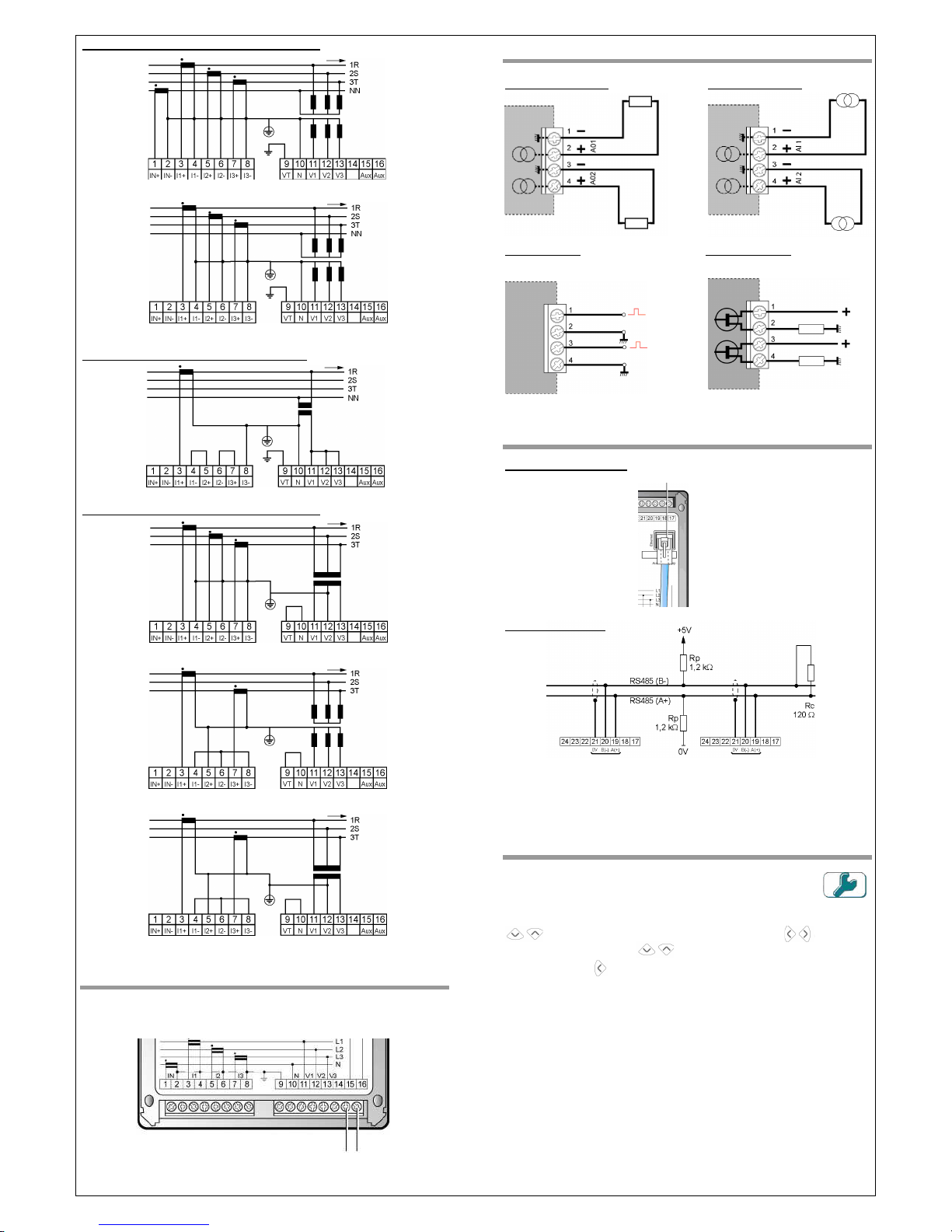
You will find below the mains wiring diagram on electrical network.
To be aware of the other wiring diagram, please consult the handbook MS1-
7352 (Available on the CD enclosed with the box).
Page 2
MMSS11--77339988 // 001
1
Page 2 / 2
UNBALANCED THREE PHASE NETWORK - 4 WIRES
S02
S08
BALANCED THREE PHASE NETWORK - 4 WIRES
S06
UNBALANCED THREE PHASE NETWORK - 3 WIRES
S09
S11
S12
P
OWER SUPPLY CONNECTION
O
PTIONAL CARDS WIRING
A
NALOGUE OUTPUTS
A
NALOGUE INPUTS
ON-
OFF INPUTS
ON-OFF OUTPUTS
(Pulses, alarm or synchronization) (Pulses or alarm)
RS485 & E
THERNET CONNECTION
E
THERNET CONNECTION
RS485
CONNECTION
NB :
1. Ethernet & RS485 options cannot be available simultaneously
2. For the RS485 network connection refer to standard in force
P
ARAMETERS LOCAL CONFIGURATION
It has to be done through the configuration menu by selecting the
icon beside and pressing the key OK
Then in each menu, select the parameter to be modified with the keys
Then select the value to be modified with the key
Each value
is modifiable with the key
.
Validate with key OK. Go back to the
menu with the key
In case of no action on keys during more than 3 minutes, the
backlight is turned in standby mode.
ENERIUM 100, 110, 200, 210, 300 or 310 can be configured with
the software E.Set supplied in each box. Communication with the
product can be carried out localy with the optical head supplied in
option or by remote control via RS485 (MODBUS RTU protocol) or
Ethernet (MODBUS/TCP RTU).
RJ45 port
80…265 Vac & 110…375 Vdc
19,2…57,6 Vdc (Low level version)
Enerdis
16, rue Georges Besse Silic 44
92182 ANTONY Cedex - FRANCE
Tel. : (33) 01 75 60 10 30 | Fax : (33) 01 46 66 62 54
[email protected] | www.enerdis.fr
 Loading...