

Page 1

JECTOR
CONTAINER EJECT SYSTEM
ML0068-001-02
OWNERS REFERENCE MANUAL
Enercon Industries Corp.
W140 N9572 Fountain Blvd.
P.O. Box (53052-0773)
Menomonee Falls, WI 53051
Phone: (262) 255-6070
Fax: (2 62) 255-7784
E-mail: [email protected]
Web Site: www.enerconind.com
01/07/2003
Page 2

EJECT SYSTEM
TABLE OF CONTENTS
SECTION 1 – INTRODUCTION................................................................................................................................... 1
SAFETIES AND WARNINGS.......................................................................................................................1
GENERAL....................................................................................................................................................2
EJECT SYSTEM FEA TU R ES.......................................................................................................................2
EJECT SYSTEM SPEC IFICATIONS............................................................................................................2
SECTION 2- INSTALLATION.......................................................................................................................................3
UNPACKAGING AND INSPECTION............................................................................................................3
EJECT SYSTEM CONTROL BOX................................................................................................................3
COMPRESSED AIR.....................................................................................................................................3
EJECT SI GN AL............................................................................................................................................ 3
INPUT POWER
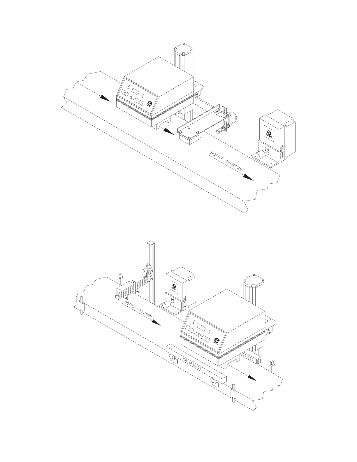
EJECT SYSTEM INSTALLATION WITH FOIL LINER DETECTOR (Figure 1)...............................................4
EJECT SYSTEM INTAL L AT ION WITH CAP INSPECTION SYSTEM (Figure 2)............................................4
SECTION 3 – PRINCIPLES OF OPERATION............................................................................................................5
METHOD OF OPERAT ION..........................................................................................................................5
SECTION 4 – EJECT SYSTEM MAINTENANCE..............................................................................................................6
CLEANING...................................................................................................................................................6
ADJUSTING.................................................................................................................................................6
SECTION 5 – TROUBLESHOOTING..........................................................................................................................7
SECTION 6 – PARTS LIST ..........................................................................................................................................8
GENERAL....................................................................................................................................................8
DESCRIPTION.............................................................................................................................................8
HOW TO USE TH IS P AR TS LIST................................................................................................................8
HOW TO ORD ER P AR TS............................................................................................................................8
EJECTOR PARTS BREAKDOWN (Figure 3)................................................................................................9
SECTION 7– MISCELLANEOUS...............................................................................................................................10
EJECT SYSTEM PRODUCTION SETUP...................................................................................................10
NOTES.......................................................................................................................................................11
.................................................................................................................................3
Page 3

SECTION 1 – INTRODUCTION
WARNING
Please read carefully before installing or servicing.
HIGH VOLTAGE is present within the control box enclosure. Install according to local electrical codes to
insure personnel safety. When
disconnected and locked out before making contact with the equipment.
As with any piece of
associated drawings furnished before applying power. Proper connections and operation are required for safe
use.
FOLLOW INSTRUCTIONS for safety of personnel when operating or maintaining this equipment.
Before you install this Eject System, you should
take the time to carefully read all the instructions
contained in this manual.
Before installing, wiring, starting, operating or
making any adjustments, identify the components
of th e Eject System, usi ng thi s m an ual as a guide.
The operator should use common sense and good
working practices while operating and maintaining
this unit. Check the safety devices following the
procedures contained in this manual.
Qualified personnel, adequately equipped with
proper tools should do maintenance. Follow the
maintenance schedules as outlined in the manual
to insure problem free operation after start-up.
Safety instructions in this manual are bold-faced for
emphasis. The signal words WARNING and
CAUTION are used to indicate hazard seriousness
levels as follows:
ELECTRICAL equipment, one should become familiar with the manual and all
SERVICING, technician must insure that external electrical power is
SAF E TY AND WA R NING
Caution is used to indicate the presence of a
hazard, which will or can cause minor
personal injury or property damage if the
caution is ignored.
Warning is used to indicate the presence of a
hazard which can cause severe personal
injury, death, or substantial property
damage, if the warning is ignored.
*** CAUTION ***
*** WARNI NG ***
ML0068-001-02 Container Eject System ENERCON INDUSTRIES
1
Page 4
GENERAL
The Enercon Eject System was desi gn ed to pr ovide
the packaging industry with a simple system to
eject bad containers off a conveyer. The eject
system can be used with any “bad container”
detectors, such as; missing foil detectors, high cap
detectors and missing cap detectors to name a few.
The system accepts a contact closure from the
desired “bad container” detector which starts a
delay timer. Once timed out, the eject timer is
activated, causing the plunger to eject the container
off the conveyor.
EJECT SYSTEM FEATURES
a. Delay timer
Used to set the time from when the bad
container is detected to when the container
reaches the eject zone.
b. Eject time
Used to set the time for how long the eject
plunger is activated.
c. Cylinder speed adjust
Used to set the extension and retraction
speed of the pl un ger .
d. Air pressure regulator and gauge
Used to set the forc e o f the pl un ger .
EJECT SYSTEM SPECIFICATIONS
Electrical
a. A power cord is supplied for customer
connection to a local power source. The
power required is either 120VAC or 240VAC ±
10%, 50/60 Hz, 1ph, 2A. Check rating plate of
eject system for correct voltage.
b. A 12ft. two conductor cable is also supplied
for the external signal input.
Air requirements
a. Filtered air is required at 70-90 PSI.
BE SURE ALL POWER IS DISCONNECTED AND
LOCKED OUT FROM UNIT BEFORE PERFORMING
ANY PREVENTATIVE MAINTENANCE PROCEDURES.
*** WARNI NG ***
ML0068-001-02 Container Eject System ENERCON INDUSTRIES
2
Page 5

SECTION 2- INSTALLATION
UNPACKAGING AND INSPECTION
Carefully open all shipping containers and remove
the contents. Each item should be thoroughly
inspected for dama ge.
NOTE: Be extra careful if using a sharp instrument
when removing the protective wrapping from the
equipment. File a claim with the freight carrier for
any damage incurred. Enercon Industries should
also be contacted as soon as possible to expedite
the shipment of replacements parts.
CONTACT:
Enercon Customer Service Department
Phone Number: (262) 255-6070
Fax Number: (262) 255-2462
E-Mail Address: [email protected]
Website: www.enerconind.com
24hr Customer Service is available.
IMPORTANT:
If concealed loss or damage is discovered after
delivery, notify your carrier at once and request an
inspection. This is absolutely necessary for the
carrier to consider your claim. If damage is
detected, be sure to note it on freight bill before
signing it to acknowledge receipt. The carrier agent
should make an inspection and issue a loss or
damage report. If you give the carrier a clear
receipt for goods that have been damaged or lost in
transit, you do s o at your ow n ris k and expense.
EJECT SYSTEM CONTROL BOX
The eject system control box should be mounted
near the bad container detection system that is
being used. If the eject system is being used with
an Enercon supplied Foil Liner Detector it should
be mounted “downstream” of the detector (See
Figure 1). If the eject system is being used with an
Enercon supplied Cap Inspection System it should
be mounted between the high cap sensor and the
power supply (See Figure 2). The eject system
must be mounted no further than 9.99 seconds
“down stream” due to the maximum range of the
delay timer. To calculate the maximum distance the
ejector can be mounted from the bad container
detector simply multiply the conveyer speed in
feet/second times 9.99 seconds. The ejector should
ML0068-001-02 Container Eject System ENERCON INDUSTRIES
then be mounted somewhere within this window.
The ejector can then be mounted on the side of the
conveyor using the angle brackets and hardware
suppl ied.
COMPRESSED AIR
Once the eject system control box has been
installed, filtered compressed air (70-90 PSI) will
need to be supplied to the control box (see the
installation diagram for the location). For ease of
installation, a one – touch fitting for 3/8 outside
diameter plastic tubing is supplied.
EJECT SIGNAL
The eject control box requires a normally open
contact signal that momentarily closes from the bad
container detector for activation. A 12ft twoconductor cable for this signal is supplied. If you
have purchased this for an Enercon cap sealer this
cord will have a plug on the end which is to be
connected to the back of the power supply.
INPUT POWER
A power cord is supplied with the eject system and
can be plugged into a standard 120V receptacle to
power the system. (240V power is optional.
Observe the rating plate for the correct voltage)
3
Page 6
EJECT SYSTEM INSTALLATION WITH FOIL LINER DETECTOR
Figure 1
EJECT SYSTEM INTALLATION WITH CAP INSPECTION SYSTEM
Figure 2
ML0068-001-02 Container Eject System ENERCON INDUSTRIES
4
Page 7

SECTION 3 – PRINCIPLES OF OPERATION
METHOD OF OPERATION
Once the eject system has been installed, adjust
the air pressure regulator to 70 PSI. Apply power to
the eject system by using the power on switch on
the right side of the box to turn the unit on. (Insure
the timer displays energize with power applied.)
The system is now ready for testing and calibrating.
The eject system is designed to use an external
eject signal from a bad container detector. Upon
receiving an eject signal, the delay timer is
activated. As the bad container approaches the
eject box, the de lay timer will time out. Once timed
out the plunger will be act ivated for a set time and
consequently push the container off the conveyor.
If the plunger activates prior to the container
reaching the plunger increase the delay time by
using the up arrow and repeat the test. Continue
this process until the plunger makes contact with
the center of the container as it passes in front of
the p l unger.
If the plunger activates after the container reaches
the plunger decrease the delay time by using the
down arrow and repeat the test. Continue this
process until the plunger makes contact with the
center of the container as it passes in front of the
plunger.
The amount of time the plunger is in the extended
position is also adjustable and can be increased or
decreased by using the up/down arrows. (It is
recommended to adjust this time to approximately
0.08 seconds as a starting point when setting up
the syst e m) Thi s t ime r sh ou ld no t be ope rat ed wit h
a timer setting longer then the delay timer setting
To ensure the proper ejection on the container you
may need to adjust the speed of the cylinder
plunger by adjusting the speed control valves
located on the front of the eject box.
NOTE: The ejector was designed with a built in
cache of 29 containers, which means a total of 29
bad containers can occur between when a bad
container is sensed and when the first bad
container is ejected. This should be more than
adequate for the spacing between the detection
device and the eject system. (If more than 29
containers are detected before the first bottle is
ejected the timing func tion of th e ejector will be out
of synchronization.)
ML0068-001-02 Container Eject System ENERCON INDUSTRIES
5
Page 8

SECTION 4 – EJECT SYSTEM MAINTENANCE
Due to the nature of this system the amount of maintenance required will be minimal. The main priority for
maintenance will be keeping the unit and air supply clean and properly adjusted.
CLEANING
As long as clean air is supplied to the ejector
minimal cleaning is required for proper operation.
ADJUSTING
If the line speed or product type does not change
there should be no reason to make any
adjustments to the system, however you may want
to periodically check the mounting hardware, if this
loosens the timing of the system may be thrown off.
NOTE: For each new product that is run you may
have to adjust the eject delay, eject time and
plunger speed to ensure proper ejects.
ML0068-001-02 Container Eject System ENERCON INDUSTRIES
6
Page 9

SECTION 5 – TR OUBLESHOOTING
SYMPTON
No power to the control box.
(Seven segment LED’s do not light)
Eject plunger does not function
Ejector timing seems to change
Delay time or eject time are not
adjustable
BE SURE ALL POWER IS DISCONNECTED
AND LOCKED OUT FROM UNIT BEFORE
PERFORMING CHECK.
1. Check the input power
2. Is the power switch on at the power entry
module
3. Check the fuse inside the power entry module
4. Remove power and open the box and ensure
the ribbon cable is properly connected between
the display board and the ejector control board
5. Contact Enercon service department for
assistance
1. Check the eject signal
2. Check for proper inl et ai r pressure
3. Remove power and open the box and inspect
the hose connections, looking for an open hose
or a kink in a hose.
4. Check solenoid wiring
5. Possible bad solenoid
6. Contact Enercon service department for
assistance
1. Are the containers sliding on the conveyor?
2. Is the conveyor speed changing?
3. Check the “bad container” detector for proper
adjustment.
1. Remove input power and open the box and
ensure the ribbon cable is properly connected
between the display board and the eject control
board
2. Bad display board
3. Bad eject control board
4. Contact Enercon service department for
assistance
*** WARNI NG ***
CHECK
ML0068-001-02 Container Eject System ENERCON INDUSTRIES
7
Page 10

SECTION 6 – PARTS LIST
GENERAL
This manual, which contains an illustrated parts
breakdown, has been prepared as an aid in
identifying and ordering parts in the ejector. All of
the parts listed in the parts breakdown are
manufactured with the same precision as the
original equipment.
DESCRIPTION
The illustrated parts breakdown illustrates the
various assemblies, sub-assemblies and detailed
parts that make up the ejector. The following
illustration shows each part clea rly and in its correct
location relative to the other part s in the illust ration.
The description and quantity required per station is
listed in numerical order on the f ollowing pages.
HOW TO USE THIS PARTS LIST
1. Turn to the Parts Section to locate the desired
illustrations.
2. Locate the part on the illustration by visual
identification and the Index Number.
3. Find the Index Number on the tabu late d pa ge,
along with the description.
HOW TO ORDER PARTS
In order that all avoidable errors are eliminated
when ordering parts, please specify the following:
1. The Model Number of the unit as shown on the
Ejector Rating Plate.
2. The Serial Number of the unit as shown on the
Ejector Rating Plate.
3. The Form Number of this manual located on
cover.
4. The Part Number, description and quantity
needed exactly as listed on parts breakdown
drawings.
To order, contact:
Enercon Customer Service Department
Phone Number: (262) 255-6070
Fax Number: (262) 255-2462
E-Mail Address: [email protected]
Website: www.enerconind.com
24hr Customer Service is available.
ML0068-001-02 Container Eject System ENERCON INDUSTRIES
8
Page 11
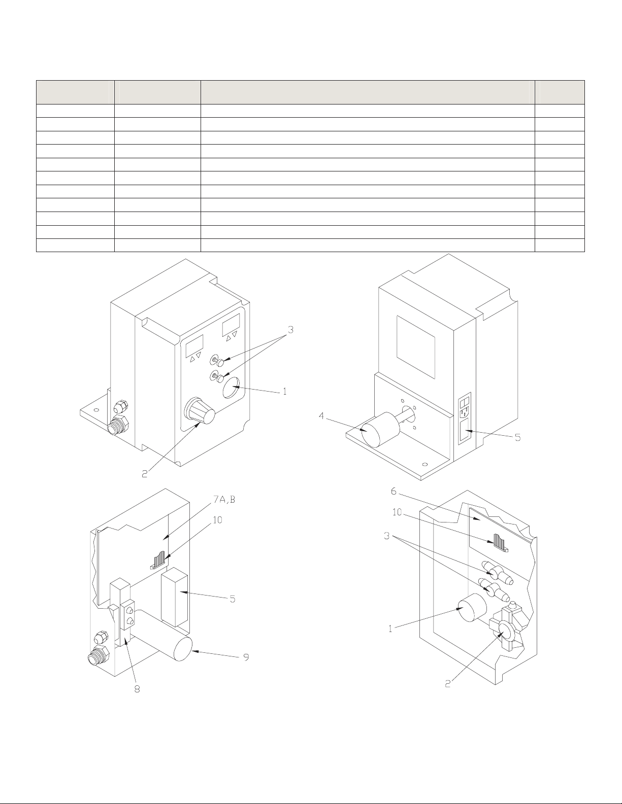
EJECTOR PARTS BREAKDOWN
INDEX NO. PART NO. DESCRIPTION QTY.
1 PN0093 Pressure Gauge, Panel Mount 1
2 PN0092 Regulator, Panel Mount 1
3 PN0091 Flow Control, Panel Mount 2
4 HW0101 Bumper 1
5 CN0059 Power Entry Module 1
6 LM4439-01 Eject Display Board 1
7A LM4440-01 Eject Control Board (120 VAC) 1
7B LM4440-02 Eject Control Board (240 VAC) 1
8 PN0090 Body Ported Valve, Dual Solenoid 1
9 PN0094 Air Cylinder 1
10 CA1085 20 Pin Ribbon Cable 1
Figure 3
ML0068-001-02 Container Eject System ENERCON INDUSTRIES
9
Page 12

Ejects (Y/N)
SECTION 7 – MISCELLANEOUS
EJECT SYSTEM PRODUCTION SET-UP
Product
Delay
Time
Eject
Time
Plunger
Speed
Air
Pressure
Line
Speed
High Cap
Missing Foil
Ejects (Y/N)
ML0068-001-02 Container Eject System ENERCON INDUSTRIES
10
Page 13

NOTES
________________________________________________________________________________
________________________________________________________________________________
________________________________________________________________________________
________________________________________________________________________________
________________________________________________________________________________
________________________________________________________________________________
________________________________________________________________________________
________________________________________________________________________________
________________________________________________________________________________
________________________________________________________________________________
________________________________________________________________________________
________________________________________________________________________________
________________________________________________________________________________
________________________________________________________________________________
________________________________________________________________________________
________________________________________________________________________________
________________________________________________________________________________
________________________________________________________________________________
________________________________________________________________________________
________________________________________________________________________________
________________________________________________________________________________
________________________________________________________________________________
________________________________________________________________________________
________________________________________________________________________________
________________________________________________________________________________
________________________________________________________________________________
________________________________________________________________________________
________________________________________________________________________________
________________________________________________________________________________
________________________________________________________________________________
________________________________________________________________________________
________________________________________________________________________________
________________________________________________________________________________
________________________________________________________________________________
________________________________________________________________________________
________________________________________________________________________________
________________________________________________________________________________
________________________________________________________________________________
________________________________________________________________________________
________________________________________________________________________________
________________________________________________________________________________
________________________________________________________________________________
________________________________________________________________________________
________________________________________________________________________________
________________________________________________________________________________
________________________________________________________________________________
ML0068-001-02 Container Eject System ENERCON INDUSTRIES
11
 Loading...