

Page 1

Optimizing Pain Management and Rehabilitation
CTM Controller® 1600
Operating Manual
Important product information. Do not throw away or destroy.
Rév. 1.1 | 2017-12-12
Page 2

2 www.ener-c.com www.ener-c.com 3
We are grateful that we have been able to convince you of the benets of
CTM Therapy® and that you have bought the CTM Controller® 1600.
The CTM Controller® 1600 is a very light, mobile cold and heat therapy
device for using CTM Therapy®, which supports improved rehabilitation
and pain management. The CTM Controller® 1600 enables controlled
cold treatment in a constant therapeutic temperature range of 8 to 18°C
(46 to 64°F) and controlled heat treatment in a constant therapeutic
temperature range of 38 to 42°C (100 to 108°F).
Please read this operating manual through thoroughly, so as to guarantee
the maximum safety and benets of the CTM Controller® 1600.
The CTM Controller® 1600 is intended to be used by physicians and
patients.
Patients can operate the device after an adequate training by qualied
clinicians, no restrictions in functions described in this User Manual
are applied.
The CTM Controller® 1600 is designed to be used for a period of 10 years
when subjected to regular maintenance.
The CTM Exchanger® shall be used for one patient only for the extension
of the treatment.
Table of contents
A. Important safety information 4
B. General safety and usage instructions 5
C. Components 6
Control unit 7
Control panel 7
D. CTM Controller® 1600 setup 8
Connecting the tube and the CTM Exchanger® 9
Filling the control unit with water 9
E. Operation 10
Recommended procedure for therapeutic cooling 10
Recommended procedure for therapeutic heating 11
Display current temperature 11
Timer function 11
F. Maintenance 12
G. Troubleshooting 12
H. CTM Exchanger® 14
Appendix A – Explanation of symbols 15
Appendix B – Manufacturer‘s declaration 16
Ener-C | CTM Controller® 1600 | Operating manual | Rev. 1.1 | 2017-12-12 Ener-C | CTM Controller® 1600 | Operating manual | Rev. 1.1 | 2017-12-12
CTM Controller® 1600 specications and data
Weight (net) 5.0 kg (control unit)
Dimensions 300 mm x 260 mm x 184 mm
Input 230 V, 50 Hz, 260 W
Water temperature 8 °C – 42 °C (normal tap water)
Operating temperature 5 °C – 35 °C (optimal room temperature below 25 °C) *
Transport and storage temperature 5 °C – 40 °C *
* Relative humidity 10% to 90%
Page 3

4 www.ener-c.com www.ener-c.com 5
A. Important safety information
Warning
The CTM Controller® 1600 supplies benecial cold and heat to support rehabilitation and pain
reduction. If you have a serious illness or injury, always ask your doctor or another qualied medical
specialist before using the CTM Controller® 1600.
NEVER use the CTM Controller® 1600 on people who are sensitive to heat or cold, on people with
a reduced state of consciousness or on children under 12 years of age.
NEVER sleep while using the CTM Controller® 1600.
NEVER use the CTM Controller® 1600 for cold therapy under one of the following conditions:
• Cold allergies (cold urticaria) or • Clear reaction to the cold pressor test
cold intolerance • On areas with regenerating peripheral nerves
• Raynaud's syndrome or phenomenon • On areas with circulatory problems or
• Cryoglobulinemia peripheral vascular diseases
• Paroxysmal cold haemoglobinuria • Pregnancy
NEVER use the CTM Controller® 1600 for heat therapy under one of the following conditions:
• Diabetes mellitus • Spinal cord injuries
• Multiple sclerosis • Rheumatic disorders
• Peripheral vascular diseases • Pregnancy
NOTE: In case of haematomas the heat treatment might not be indicated
NOTE: Some products can cause early degradation of the CTM Exchangers® which may lead to material
failure or leaks. This is not covered by the warranty.
WARNING: The CTM Controller®1600 is not waterproof. Protect the device from water at any time!
Always protect the device with the plastic zip-bag provided with the package, for transport and storage.
If water or any other liquid is spilled on it wipe it o immediately with a damp cloth.
Do not use the CTM Controller® 1600 if wet, or connect it to a power outlet with wet hands.
B. General safety and usage instructions
Do not use the CTM Controller® 1600 and CTM Exchanger® with other devices unless described in
this User Manual.
The CTM Controller® 1600 is intended for indoor use in a dry and well-ventilated environment.
A distance of at least 30 cm (12“) should be left free on all sides of the device in order to ensure
sucient air circulation.
The CTM Controller® 1600 must be lled with water prior to use. See “CTM Controller® 1600 setup” for
the instructions for setting up and lling the appliance.
Before lling with water or emptying, the device must always be switched o and disconnected from
the power supply.
Never use caustic or ammable liquids in the CTM Controller® 1600. Only use clean tap water or
distilled water for the device.
Make sure that the tubes and CTM Exchangers® are properly connected before you switch on the device.
Empty the CTM Controller® 1600 before it is transported and/or stored at temperatures around freezing
point.
Transport the CTM Controller® 1600 with care. Shocks or tilting may result in damage to the device
components.
Keep the CTM Controller®1600 and the CTM Exchanger® out of the reach of unsupervised infants and
children.
Do not clean the CTM Controller® 1600 with solvents, but only with a damp cloth.
Do not disassemble or attempt to repair the CTM Controller® 1600. Leave all maintenance work and repairs
to a qualied technician.
In case of maintenance, repair or changes in the performance contact Ener-C. Contact information is
provided on the last page of the manual or on www.ener-c.com.
This equipment generates, uses and can radiate radio frequency energy and, if not installed and used in
accordance with the instructions, may cause harmful interference to other devices in the vicinity. However,
there is no guarantee that interference will not occur in a particular installation.
The device is intended for use in orthopedic centers, therapy clinics, athletic training facilities, hospitals,
nursing facilities, medical centers, as well as in patient homes. The device should not be used in an
environment where the intensity of electromagnetic disturbance is high.
NOTE: do not store the device in direct sunlight. Keep dry.
NOTE: Do not operate the device in direct sunlight.
Ener-C | CTM Controller® 1600 | Operating manual | A. Important safety information | Rev. 1.1 | 2017-12-12 Ener-C | CTM Controller® 1600 | Operating manual | B. General safety and usage instructions | Rev. 1.1 | 2017-12-12
Page 4
6 www.ener-c.com www.ener-c.com 7
C. Components
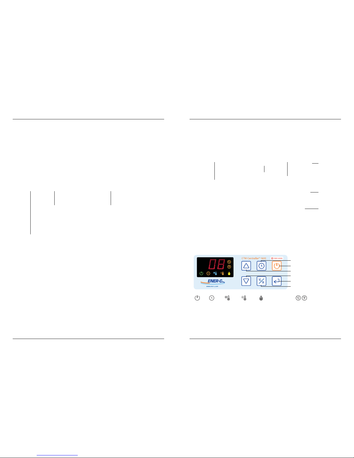
The components of the CTM Controller® 1600
1 Control unit
1 Set of tubes
1 CTM Exchanger®
There are a large number of CTM Exchanger® available for use with the CTM Controller® 1600
(see section H. CTM Exchanger®).
NOTE: The tube may be dierent in appearance from the above example.
The control unit
Cover of the
water tank
Air inlet
Handle
Mains cable
The control panel / display symbols
Low water
level
Power Timer HeatingCooling
FLASHING
Enter Temperature scale
Timer
On/O
Warmer
Cooler
Enter
Temperature scale choice
Tube CTM Exchanger® Control unit
Water level indicator (on side)
Ener-C | CTM Controller® 1600 | Operating manual | C. Components | Rev. 1.1 | 2017-12-12 Ener-C | CTM Controller® 1600 | Operating manual | C. Components | Rev. 1.1 | 2017-12-12
Control panel
Warning: User interface keys are very sensitive to touch, inadvertently touching could modify
the parameters.
Page 5
8 www.ener-c.com www.ener-c.com 9
D. CTM Controller® 1600 setup
Connecting the tube and the CTM Exchanger®
The CTM Controller® 1600 is supplied with a tube set and a CTM Exchanger® is needed for its use.
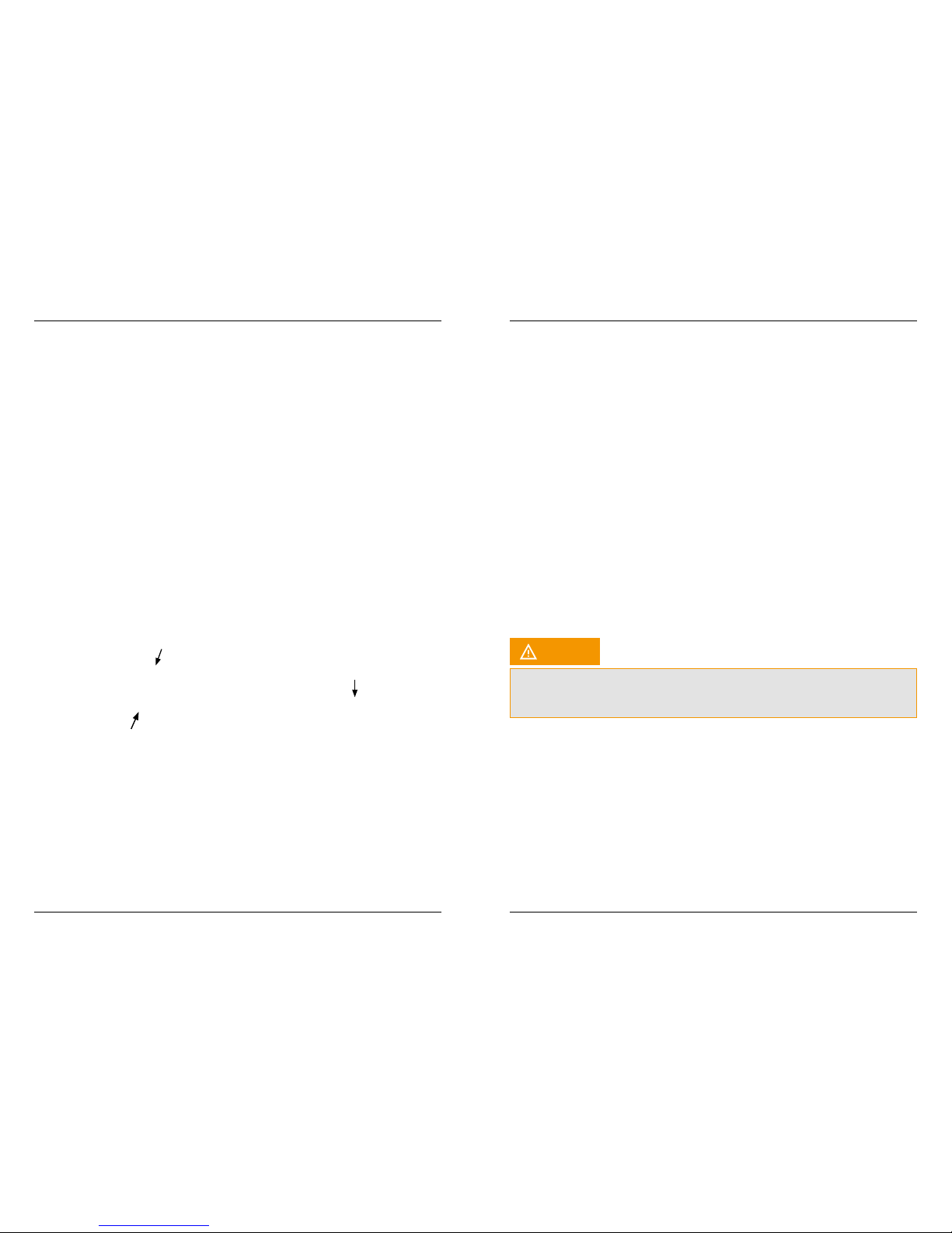
Connect the two black plastic plugs of the tube set to the control unit, as shown below. You hear a
click when the plug has properly locked into place. To remove the tube, hold the black plug and
pull it out. Please do not disconnect the plug with pulling the white tube.
Then connect the CTM Exchanger® to the tube by inserting both the CTM Exchanger® plugs into
the two sockets of the tube. Twist both halves of the connection to lock it.
A large number of specic, anatomically shaped CTM Exchangers® are available.
See section H. for further information or visit:
www.ener-c.com/ctm-exchanger
CTM Exchanger®
tube end
End of the tube
Insert plug of the
CTM Exchanger® into
tube socket and turn
to connect the tubes
Fill the control unit of the CTM Controller® 1600 with water
Before use, the control unit must be lled
with clean tap water or distilled water.
In order to ll the device completely, remove
the cover of the water tank and ll the tank
with approx. 300 ml of water with a funnel.
The water level in the tank can be read out
through the window of the water tank on the
side of the device. Avoid the tank overowing
(2/3 to 3/4 full is ideal). When the tank is full,
close it again using the cover.
As soon as the tank has been lled, connect the mains cable to a suitable socket and press the ON/OFF
button to switch the device on. The control unit then pumps the water through the tube and the
CTM Exchanger®, which may lead to the water level in the tank falling, while the tube and CTM Exchanger®
are lling with liquid. If the water level drops below half, remove the cover and slowly ll with water until
the level is again between half-full and full. Then fasten the cover again.
NOTE: The device does not function when the “Low water level” light is on. When this indicator lights up,
add more water as described above and then press the ON/OFF button to restart the device.
Do NOT immerse the control unit in water to ll the tank.
Do NOT pour or spill any water into the control unit’s ventilation openings.
Do NOT drink any water from the control unit.
Before using the device, make sure that the cover is closed so as to prevent the water from overowing.
If the CTM Exchanger® is located in a higher position than the control unit, this may lead to the tank
overowing.
Caution
Ener-C | CTM Controller® 1600 | Operating manual | D. CTM Controller® 1600 setup | Rev. 1.1 | 2017-12-12 Ener-C | CTM Controller® 1600 | Operating manual | D. CTM Controller® 1600 setup | Rev. 1.1 | 2017-12-12
Page 6

10 www.ener-c.com www.ener-c.com 11
E. Operation
The following sections contain the recommended procedures for optimum therapeutic cooling and heating.
The control unit can be set to temperatures between 8 °C (46 °F) and 42 °C (108 °F).
To switch the device on or o: press ON/OFF button.
NOTE: The Power symbol on the display blinks until the set temperature is reached.
To set the temperature: press the COOLER or WARMER
button on the control panel until the required temperature is shown.
To select °C or °F: press the TEMPERATURE SCALE button.
For optimum eciency, the control unit should be located at about the same height as the CTM Exchanger®.
Please also note that the system is designed for operation at normal ambient temperatures below 25°C (77°F).
The cooling performance is reduced at ambient temperatures above this value.
For cooling, the control unit’s fan runs at 55% output in the standard setting. Proceed as follows if you would
like to increase the output manually to 75%:
Press and hold the button for 3 seconds with the device switched on
The fan stops automatically when the set target temperature is reached. To switch o manually,
please press and hold the ENTER button again for 3 seconds.
Control unit operation in low-noise SILENT mode (40% output) as follows:
Press and hold the button for 6 seconds with the device switched on
NOTE: The device does NOT stop automatically in silent mode. It is only possible to switch o manually by
pressing and holding the ENTER button for 3 seconds again. After changing the temperature > 5 Kelvin, the
control unit's fan starts to run with the standard settings until the new set temperature is reached.
Recommended procedure for therapeutic cooling
NOTE: always follow the therapy temperature and exposure time given by the treating physician.
To isolate the device from the supply mains disconnect the power cord. Please ensure the power cord is easy
accessible and could be unplugged at any time. It is advisable to disconnect the device after each use.
Set the device to 8°C (46°F) and let it cool down until the display shows 12°C (54°F) or less. Apply the
CTM Exchanger® to the required part of the body without the tube kinking, because this impairs the ow of water.
When the CTM Exchanger® is applied to the body, the temperature displayed on the control panel goes up
by a few degrees. This is normal and means that the CTM Exchanger® is removing heat from the body.
NOTE: If the temperature rises further to above 20°C (68°F), it is likely that the ow of water has been restricted.
In this case, the cooling phase must be restarted. In order to re-establish the ow, remove the CTM Exchanger®
from the body and set the temperature to 42°C (108°F) for about 7 to 10 minutes. The ow of water should then
be re-established and you can restart the cold therapy.
WARNING: Too long application of cold can lead to frostbites and to local skin damages up to tissue necrosis.
Recommended procedure for therapeutic heating
NOTE: always follow the therapy temperature and exposure time given by the treating physician.
Set the device to 42°C (108°F) and let it heat up until the display shows 40°C (104°F) or more. Apply the
CTM Exchanger® to the required part of the body without the tube kinking, because this impairs the ow of
water.
When the CTM Exchanger® is applied to the body, the temperature displayed on the control panel falls by a
few degrees. This is normal and means that the CTM Exchanger® is supplying heat to the body.
Regularly monitor the temperature of the device and stop the treatment if the temperature drops below
8°C (46°F) or exceeds 43°C (109°F) or if discomfort occurs. If these temperatures are applied to the skin over
a long period of time, this may lead to serious injuries.
Contact the treating physician to discuss the discomfort symptoms.
Display current temperature
Only the set temperature is shown on the display during operation. The current temperature can be shown
as follows:
Press the TEMPERATURE SCALE button and hold for 2 seconds
The target temperature setting does not change in the process. The indication of the current temperature
appears for 3 seconds on the display and then disappears again.
NOTE: If the water temperature drops below 4°C or higher 47°C, the device automatically switches o.
The device can only be restarted after disconnection from the mains.
Timer function
The timer programs the device to switch o within 6 minutes to 4 hours according to the setting. This can
be set in steps of 0.1 hours. For example, a timer setting of 1 means that the device will be switched o in 1 hour.
A timer setting of 4 means that the device will be switched o in 4 hours.
When the TIMER button is pressed, the standard setting is 00.
Press the TIMER button repeatedly to set the desired time.
So that the device switches OFF at a dened time: make sure that the control unit is switched ON.
Repeatedly press the TIMER button until the desired number of 0.1 hour steps is achieved. Press the ENTER
button. The indicator light above the TIMER remains switched on. The control unit will end the heating
or cooling at the desired time.
After 4 hours without any action on the CTM Controller® 1600, the system will be automatically switched o.
Warning
Ener-C | CTM Controller® 1600 | Operating manual | E. Operation | Rev. 1.1 | 2017-12-12 Ener-C | CTM Controller® 1600 | Operating manual | E. Operation | Rev. 1.1 | 2017-12-12
Page 7

12 www.ener-c.com www.ener-c.com 13
F. Maintenance
G. Troubleshooting
The device does not
switch on
Poor cooling
or heating
performance
No power
Not connected to the power grid
Little water in the tank
Water on the control panel
Little water in the tank
Incorrect temperature set
Check if the device is plugged in.
If the mains cable is damaged, disconnect the
device from the mains and call customer service.
Connect the mains cable to the power source
Fill the water tank and press the ON/OFF button
to reset the device
Make sure that the control panel is dry
Fill the tank as described in section D.
CTM Controller® 1600 setup
Set the temperature and press the ENTER button
Ener-C | CTM Controller® 1600 | Operating manual | F. Maintenance / G. Troubleshooting | Rev. 1.1 | 2017-12-12 Ener-C | CTM Controller® 1600 | Operating manual | G. Troubleshooting | Rev. 1.1 | 2017-12-12
If this equipment does cause harmful interference to other devices, which can be determined by turning
the equipment o and on, the user is encouraged to try to correct the interference by one or more of
the following measures:
• Reorient or relocate the receiving device
• Increase the separation between the equipment. Connect the equipment into an outlet on a
circuit dierent from that to which the other device(s) are connected
• Consult the manufacturer or eld service technician for help
In the event the device experiences a loss of performance or degradation due to electromagnetic
disturbance, the device is expected to continue to operate safely. The device should not be used less
than 30 cm (12 inches) away from any portable and mobile RF communications equipment.
Message
"---"
"E1"
"E10"
"E11"
"E2"
"E3"
What it means
Water level to low
Water temperature < 4 °C
Equipment o
Water temperature Sensor
Disconnected
Equipment o
Water temperature Sensor
short circuit
Equipment o
Water temperature > 47 °C
Equipment o
Heat sink temperature > 55 °C
Equipment o
What to do
Water rell
Switch the device o and pull out the mains plug. Wait for 15 minutes, switch the
device back on and enter the desired temperature.
If the Problem occurs again, note the error message, pull out the mains plug and
call customer service
Contact Ener-C for repair
Contact Ener-C for repair
Switch the device o and pull out the mains plug. Wait for 15 minutes, switch the
device back on and enter the desired temperature.
If the Problem occurs again, note the error message, pull out the mains plug and
call customer service
Switch the device o and pull out the mains plug. Wait for 15 minutes, switch the
device back on and enter the desired temperature.
If the Problem occurs again, note the error message, pull out the mains plug and
call customer service
Cleaning the control unit
Switch the device o and pull out the mains plug. Use a clean, damp cloth to clean the outside of
the control unit. Only use mild soap when necessary. Make sure that no water gets into the device.
The CTM Controller® 1600 may be cleaned in this way as often as you like.
NEVER immerse the control unit in water and avoid any water getting into the vent openings.
Emptying the control unit
To empty the device, remove the cover of the water tank and tilt the control unit so that the water can
ow out of the tank opening. Then close the cover again.
NOTE: Always empty the control unit prior to transport or storage to prevent accidental leakage.
Storage of the device
If the device is not used for a long period of time, take the tube o the control unit. Let the water out
of the control unit as described above. Use the water drain key to let any residual water out of the control
unit, tube and CTM Exchanger®. For complete emptying, the CTM Exchanger® must be inverted so that
the tube points downwards.
Coil the cable up loosely for storage to avoid damage.
Maintenance
Ener-C recommends to perform an yearly check of the CTM Controller® 1600. Please get in contact
with Ener-C or your distributor to arrange the maintenance. The equipment needs to be sent back with
the original packaging.
The following section provides tips and instructions in case of diculties in using the CTM Controller® 1600.
In case the information is not sucient to solve the issue, unexpected events or changes in the performance
of the device please contact Ener-C or the authorized distributor in your country.
Contact information are provided at the end of this user manual or on www.ener-c-com.
Poor cooling
or heating
performance
Error message
on the control unit
display
Kinked tube
Reduced cooling performance at ambient
temperatures over 25 °C
The device is equipped with several automatic
switch-o functions to protect the system;
an error message shows that one of these
situations has occurred (E1, E10, E11, E2, E3)
Make sure that the tube and CTM Exchanger®
are not kinked or folded. See section E. Operation
Move the device into a cooler room
Switch the device o and pull out the mains
plug. Wait for 15 minutes, switch the device
back on and enter the desired temperature.
If the problem occurs again, note the error
message, pull out the mains plug and call
customer service
Page 8
14 www.ener-c.com www.ener-c.com 15
H. CTM Exchanger®
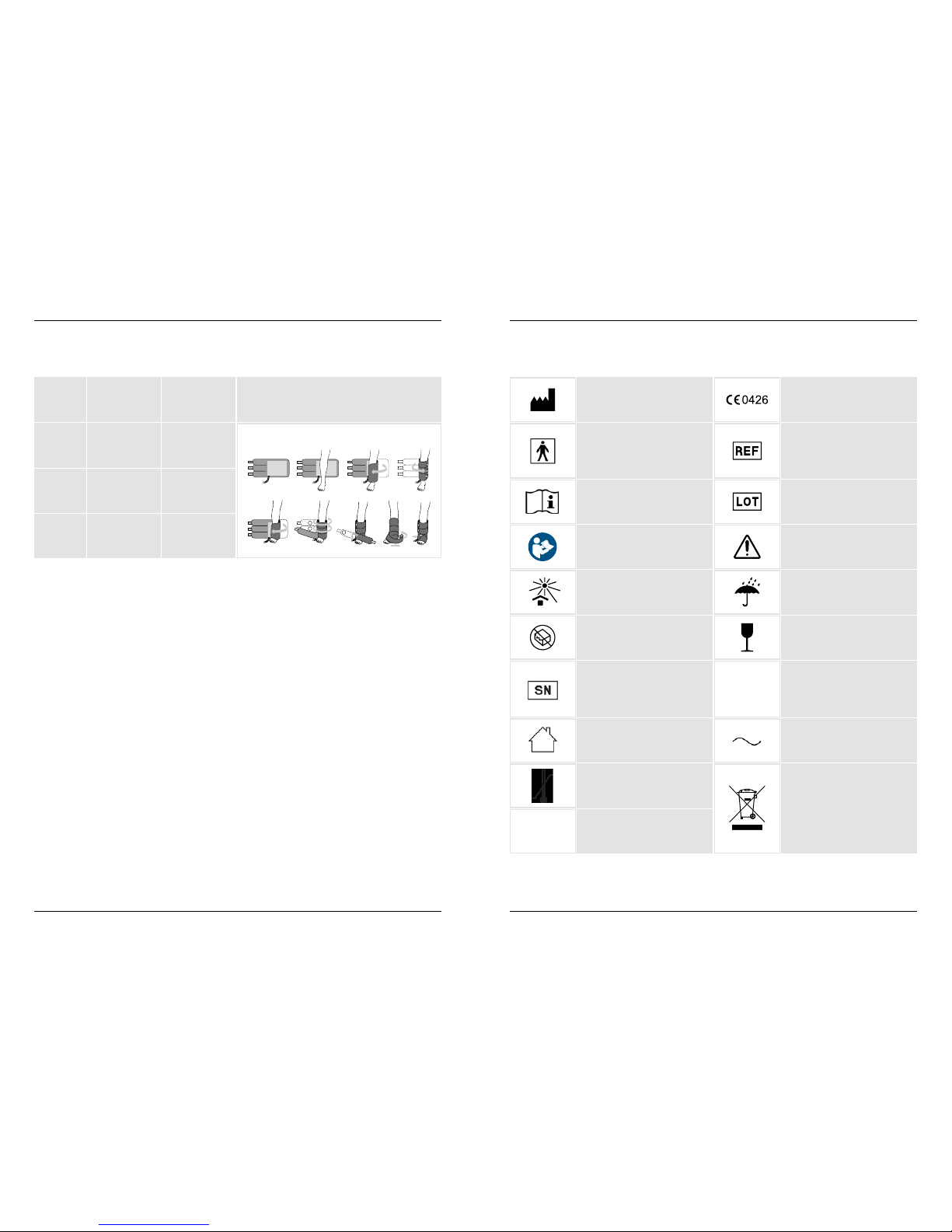
Cat. no.
CMS-01
MMM-01
MML-01
Description
Multi-purpose
small
Multi-purpose
medium
Multi-purpose
large
Maximum
size
55 cm (22“)
70 cm (28“)
84 cm (33“)
Application
For limbs and ankles
1
2
3
Appendix A – Explanation of symbols
Manufacturer
Type BF Applied Part.
Classication required for medical
devices that come in direct
contact with the patient
Consult Instructions for use
Refer to instruction manual/
booklet
Keep away from sunlight
Do not use if package is damaged
Serial Number
Indoor use only
Storage temperature limits
Storage relative humidity limits
The device complies with
European Directive MDD 93/42
EEC
Catalogue Number
Batch code
Caution / Warning
Keep dry
Fragile, handle with care
Protection against harmful ingress
of water or particulate matter
(Achieved with transport water
proof bag)
Alternating current
Waste Electrical and Electronic
Equipment (WEEE) Symbol
Product owners should refer
to their specic state and
government regulatory guidelines for proper disposal.
NOTE: Choose the correct size of the exchanger to completely cover the area to treat with
the pad where water circulates.
Cleaning the CTM Exchanger®
The CTM Exchanger® can be cleaned by wiping the plastic surface with a mild washing-up liquid in
water. Then wipe o the residual washing-up liquid with clean water. Allow to dry before using.
The CTM Exchanger® may be cleaned in this way as often as you like. It is recommended to clean
the CTM Exchanger® between uses.
NOTE: Do not under any circumstances use alcohol, aggressive cleaning agents or disinfectants
to clean the CTM Exchanger®.
NOTE: The exchangers shall be used only for one patient. In case more than one patient is treated
a new CTM Exchanger® must be used.
Ener-C | CTM Controller® 1600 | Operating manual | H. CTM Exchanger® | Rev. 1.1 | 2017-12-12 Ener-C | CTM Controller® 1600 | Operating manual | Appendix A – Explanation of symbols | Rev. 1.1 | 2017-12-12
5 °C
40 °C
IP 21
10%
90%
Page 9

16 www.ener-c.com www.ener-c.com 17
Appendix B – Manufacturer‘s declaration
This equipment has been tested and found to comply with the limits for medical devices in
EN 60601-1-2:2015. These limits are designed to provide reasonable protection against harmful
interference in a typical medical installation.
Guidance and Manufacturer’s declaration – Electromagnetic emissions
The CTM Controller® 1600 is suitable for use in the electromagnetic environment specied below.
The customer or the user of the CTM Controller® 1600 should assure that it is used in an environment
as described below.
Table 1 for Emissions
Emission Test
RF emission
CISPR 11
RF Emission
Harmonic Emissions
EN 61000-3-2
Flicker emissions
EN 61000-3-3
Compliance
Group 1
Class B
Class A
Complies
Guidance and Manufacturer’s declaration – Electromagnetic immunity
The CTM Controller® 1600 is suitable for use in the electromagnetic environment specied below. The customer
or the user of the CTM Controller® 1600 should assure that it is used in an environment as described below.
Table 2 for Transient Electromagnetic Immunity
Immunity Test
Electrostatic
Discharge (ESD)
EN 61000-4-2
Radiated RF
EN 61000-4-3
Electrical Fast
transient
EN 61000-4-4
Surge
EN61000-4-5
Conduct
disturbances
EN 61000-4-6
Power frequency
magnetic eld
(50Hz/60Hz)
EN 61000-4-8
Voltage dips, short
interruptions and
voltage variations
on power supply
input lines
IEC 61000-4-11
IEC 60601 Test
Level
± 8 kV contact
± 15 kV air
10 V/m
80 MHz to 3 GHz
± 2 kV for power
supply lines
± 1 kV for input/
output lines
± 1 kV line(s) to
line(s)
± 2 kV line(s) to
earth
10 Vrms
3 A/m
U
T
= 0% 0,5p
0°, 45°, ..., 315°
U
T
= 0% 1p
0°
U
T
= 70% 25/30p
0°
U
T
= 0% 250/300p
Electromagnetic Environment Guidance
DIPS
Interrupt
Compliance –
Level
± 8 kV contact
± 15 kV air
10 V/m
80 MHz to 3 GHz
± 2 kV for power
supply lines
± 1 kV for input/
output lines
± 1 kV line(s) to
line(s)
± 2 kV line(s) to
earth
10 Vrms
30 A/m
U
T
= 0% 0,5p
0°, 45°, ..., 315°
U
T
= 0% 1p
0°
U
T
= 70% 25/30p
0°
U
T
= 0% 250/300p
NOTE: U
T
is the AC mains voltage prior to application of the test level.
Ener-C | CTM Controller® 1600 | Operating manual | Appendix B – Manufacturer's declaration | Rev. 1.1 | 2017-12-12 Ener-C | CTM Controller® 1600 | Operating manual | Appendix B – Manufacturer's declaration | Rev. 1.1 | 2017-12-12
Page 10
18 www.ener-c.com www.ener-c.com 19
Table 3 for RF Electromagnetic Immunity
The CTM Controller® 1600 is intended for use in the electromagnetic environment specied below.
The customer or the user of the CTM Controller® 1600 should assure that it is used in such an environment.
Immunity Test
Conducted RF
IEC 61000-4-6
Radiated RF
IEC 61000-4-3
IEC 60601 Test
Level
10 Vrms
150 kHz to 80 MHz
10 V/m
80 MHz to 800 MHz
10 V/m
800 MHz to 2.5 GHz
Recommended Separation distance
Portable and mobile RF communications
equipment should be used no closer to any part
of the CTM Controller® 1600, including cables,
than the recommended separation distance
calculated from the equation applicable to the
frequency of the transmitter.
Recommended separation distance
d = 1.2 √P 80 MHz to 800 MHz
d = 1.2 √P 80 MHz to 800 MHz
d = 2.3 √P 800 MHz to 2.5 GHz
Where P is the maximum output power rating
of the transmitter in watts (W) according to the
transmitter manufacturer and d is the recommended separation distance in meters (m).
Field strengths from xed RF transmitters, as
determined by an electromagnetic site survey
a
should be less than the compliance level in each
frequency range.
b
Interference may occur in the
vicinity of equipment marked with the following
symbol:
Compliance –
Level
V1 = 10 Vrms
150 kHz to 80 MHz
E1 = 10 V/m
80 MHz to 800 MHz
E2 = 10 V/m
800 MHz to 2.5 GHz
NOTE 1: At 80 MHz and 800 MHz, the higher frequency range applies.
NOTE 2: These guidelines may not apply in all situations. Electromagnetic propagation is aected by
absorption and reection from structures, objects and people.
a
Field strengths from xed transmitters, such as base stations for radio (cellular/cordless) telephones
and land mobile radios, amateur radio, AM and FM radio broadcast and TV broadcast cannot be predicted
theoretically with accuracy. To assess the electromagnetic environment due to xed RF transmitters,
an electromagnetic site survey should be considered. If the measured eld strength in the location in which
the CTM Controller® 1600 is used exceeds the applicable RF compliance level above, the CTM Controller® 1600
should be observed to verify normal operation. If abnormal performance is observed, additional measures
may be necessary, such as reorienting or relocating the CTM Controller® 1600.
b
Over the frequency range 150 kHz to 80 MHz, eld strengths should be less than 3 V/m.
Ener-C | CTM Controller® 1600 | Operating manual | Appendix B – Manufacturer's declaration | Rev. 1.1 | 2017-12-12 Ener-C | CTM Controller® 1600 | Operating manual | Rev. 1.1 | 2017-12-12
Ener-C AG
Museggstrasse 8
6004 Lucerne
Switzerland
Optimizing Pain Management and Rehabilitation
T +41 41 226 45 68
F +41 41 226 45 73
[email protected]
www.ener-c.com
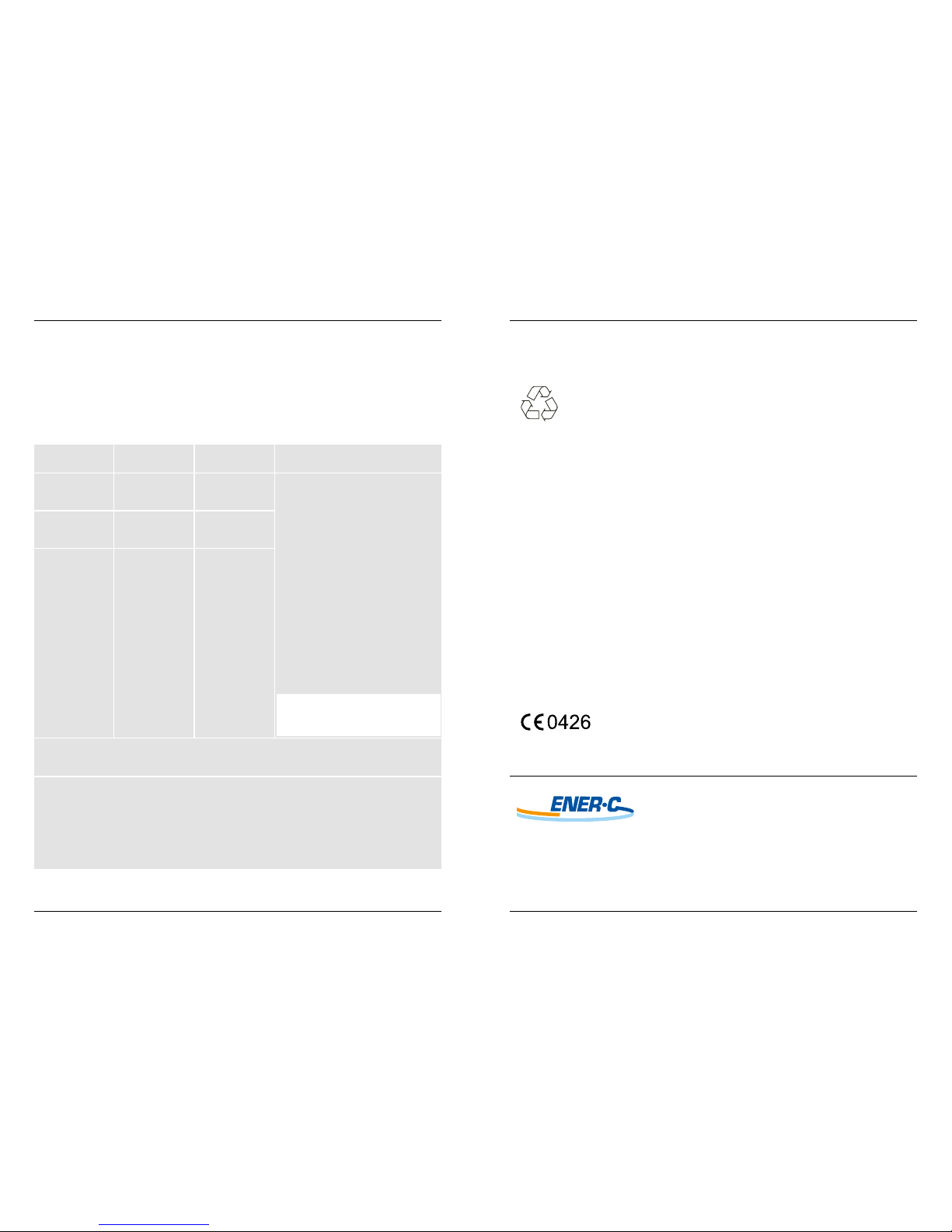
Dispose of the unit and pads in a manner that is consistent
with your federal, state, and local laws and regulations.
 Loading...