

Page 1
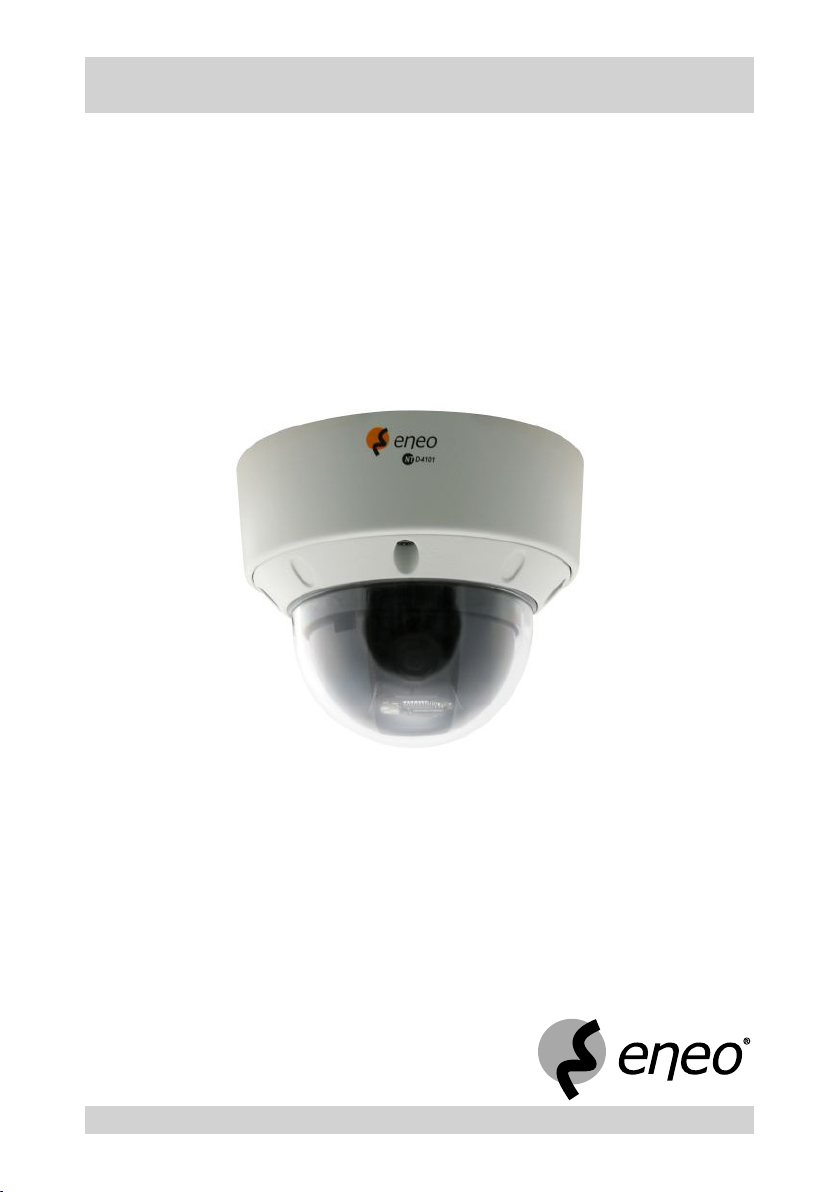
Operating Instructions
1/4“ Network Colour Mini Dome Camera
Model: NTD-4101
Page 2

Page 3

Safety Instructions
EMC class
This camera is a class A digital device to EN55022.
►
This device may cause interference to other equipment in domestic use. In such cases the persons opera-
►
ting the DVR are required to provide appropriate countermeasures, for which they themselves bear the cost.
Importance of these Operating Instructions
Please read the safety instructions and the other information contained in the Operating Instructions before
►
connecting and operating the camera.
The Operating Instructions should be kept in a safe place for later reference.
►
Environmental conditions of the camera
The camera should be protected against excessive heat, dust, humidity and vibration.
►
The camera should be protected against penetrating water and humidity which can cause permanent
►
damage.
The camera may only be operated at temperatures between 0°C and +40°C, and up to a maximum air
►
humidity of 85%.
Handling the camera
Never switch on the camera when it is humid at the inside. In such cases, have the camera checked by a
►
qualied service engineer.
The housing may only be opened by authorised persons. Repairs may only be carried out by qualied
►
service personnel.
Prior to opening the camera you must interrupt the power supply to the camera.
►
First camera operation
Never use the camera outside its specications. The camera can be destroyed if you do.
►
Never direct the camera towards the sun when the iris is open. This destroys the optical sensor.
►
When laying the connecting cables, make sure no weight is placed on them, that they are not kinked or
►
damaged, and that no humidity can penetrate them.
Cleaning the camera
Use only a damp cloth for cleaning the camera housing. Never use a wet cloth.
►
Use only a mild detergent to clean the housing. Do not use solvent-containing detergents or benzene. This
►
could permanently damage the surface nish.
Spare parts
Use only original spare parts from Videor E. Hartig GmbH.►
NTD-4101
3
Page 4

Page 5

Table of contents
Overview 7
Package contents 7
Basis functions 7
Features 7
Requirements for operation 7
Control options 7
Design and connections of the camera 8
Terminating the camera (RS-485) 9
Getting Started 10
Checklist for rst camera operation 10
Network Connection Setup 11
Installing the Camera 12
Installation at the monitoring point 12
Installing the safety rope 12
Drilling template 13
Opening the dome cover 14
Closing and securing the dome cover 14
Installation on ceiling or wall 15
Installing the heater kit 16
Cable routing in the pipe 16
Connecting the Camera 17
Connecting the power supply 17
Video connection 17
Audio connection input 17
Audio connection output 17
Network connection 17
Alarm connection input 17
RS-485 connection 17
Camera settings 18
Selecting the colour standard 18
Selecting the control protocol 18
Setting the ID address 18
Multiplexer in the network 19
Operation via system keypad 20
Joystick menu functions 20
Keypad menu functions 20
Camera menu operation 21
Invoking menu settings 21
Controlling the camera during menu operation 21
Saving presets via the system keypad 22
Camera movement with enabled automatic image reversal 22
Resetting alarm 22
Operation via web browser 23
NTD-4101
5
Page 6

Table of contents
Camera Menu Overview 24
Menu Descriptions – Camera Menu 26
PRESET (xed positions) 27
TOUR (camera movements) 28
AUTO SCAN (automatic scanning) 29
ALARM 30
CAMERA SETUP 31
DOME-SETUP 36
EXIT 37
Setting up Network Connectivity 38
Allocating or changing the camera IP address 38
Camera Control via NT-Manager 39
NT-Manager main menu 39
Additional information 39
Logging on the camera in the network 40
Camera Control via Web Browser 41
Connecting camera with web browser 41
Possible Errors and Solutions 42
Specications NTD-4101 43
Accessories 46
Dimensional Drawings 47
Index 48
Notes on disposal 50
6
NTD-4101
Page 7

Overview
Package contents
●
1/4“ network colour mini dome camera with 10x zoom lens, 720 x 576, 12 VDC
●
Power supply unit 230 V/12 VDC
●
Connecting cable for RS-485 and alarm
●
Base kit xing material
●
Drilling template
●
Safety rope
●
RJ-45 connector
●
CD with viewer software (NT-Manager), setup and client software
●
Quick start guide, complete Installation and Operating Instructions on CD
Note: The installation hardware is not supplied.
Basis functions
●
SONY CCD technology
Suitable for industrial television (CCTV)
●
●
Suitable for security monitoring
Features
1/4“ vandalism-protected IP PTZ colour dome camera
●
Zoom lens: F1.6/3.15-31.5 mm / 10x digital zoom
●
Sensitivity: 0.85 Lux at F1.2
●
High-speed shutter (MES/ESC)
●
●
On-screen menu guidance / camera title display
Max. horizontal speed: up to 120°/s
●
MPEG-4 compression
●
Transmission rate: Up to 25 ips (720 x 576 pixel)
●
Viewer for live / recording and setup
●
Pre -alarm and post-alarm recording (in the client PC)
●
Integrated web server: 10Base-T/100Base-TX
●
Event image transfer via E-mail
●
Requirements for operation
This camera must be installed by qualied personnel in agreement with the regulations for electrical and
mechanical systems that are valid at the place of installation.
Note: Please refer to www.videor.com for further information.
Control options
Analog camera menu via external system keypad (not in scope of delivery)
●
Viewer software (NT-Manager)
●
Web browser
●
NTD-4101
7
Page 8
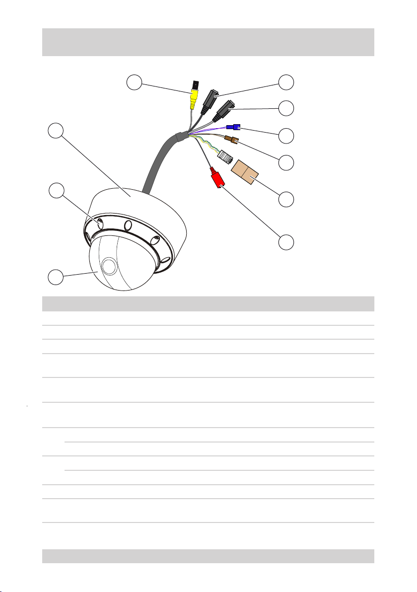
Design and connections of the camera
The following gure and the table describe the design and connecting elements of the camera:
4
5
6
3
7
8
2
9
10
1
No. Designation Function Connection of
1 Dome cover Housing part -
2 Screwed connection Dome cover attachment -
3 Dome base Dome with camera -
Monitor
4 VIDEO OUT Video output, BNC
5 AUDIO IN
6 AUDIO OUT
ALARM IN Purple: Alarm input Alarm contact
7
ALARM COMMON Blue: Alarm earth Alarm contact
RS-485(+) Black: RS-485(+) Non-inverted connection
8
RS-485(-) Brown: RS-485(-) Inverted connection
9 LAN (RJ-45) Network connection, RJ-45 Network cable
10 +12 VDC / GND Power supply
Audio input, 3.5-mm jack
connector, mono
Audio output, 3.5-mm jack
connector, mono
●
Multiplexer
●
Microphone
Active loudspeaker
●
Audio amplier
●
Power supply unit 12 VDC, protection
class 2, 12 W
8
NTD-4101
Page 9
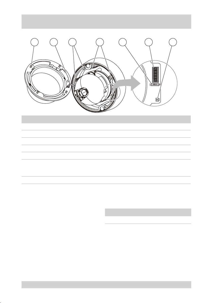
Design and connections of the camera, continued
The following gure and the table describe the design and connecting elements of the camera:
21 3 4 5 6 7
No. Designation Function
1 Screw Close and secure the dome cover (not unscrewed).
2 Retaining harness Connect dome cover with dome base.
3 Retainer Accommodate heater element heater kit (accessories).
4 Retainer Accommodate connector board heater kit (accessories).
5 Termination switch Switch RS-485 termination ON/OFF.
Select the colour standard
6 DIP switch
7 Connector Power supply for heater kit (accessories).
●
Select the control protocol
●
Set the ID address
●
Terminating the camera (RS-485)
The termination of the camera at the physical end of the RS-485 line must be activated.
Requirements:
Camera separated from the power supply.
●
Termination switch accessible.
●
Network connection conguration known.
●
NTD-4101
RS-485 of the camera Termination switch
Terminated ON
Not terminated OFF
9
Page 10

Getting Started
Checklist for rst camera operation
Step Action
1 Plan the network connection setup
2 Select colour standard, control protocol and ID address on the camera
3 If necessary, terminate the camera
4 Note down the MAC address of the camera
5 Make camera selections in the analog camera menu
6 Install the camera at the monitoring point
7
8 Install the network software
9 Log on the camera in the network
10 Operate the camera via the network
Connecting the camera
10
NTD-4101
Page 11

Network Connection Setup
The following gure shows an example of a network connection setup.
*)
*) terminated
BNC
RJ-45-Crossover
RJ-45-LAN
External Control
IP setting utility
NT-Manager
Internet
*)
NTD-4101
11
Page 12
Installing the Camera
Installation at the monitoring point
This camera is suitable for
Ceiling installation, also on suspended ceiling.
●
Wall installation.
●
Note: Suitable installation hardware see Accessories.
Danger from electric shock
DANGER!
Danger from dropping objects
DANGER!
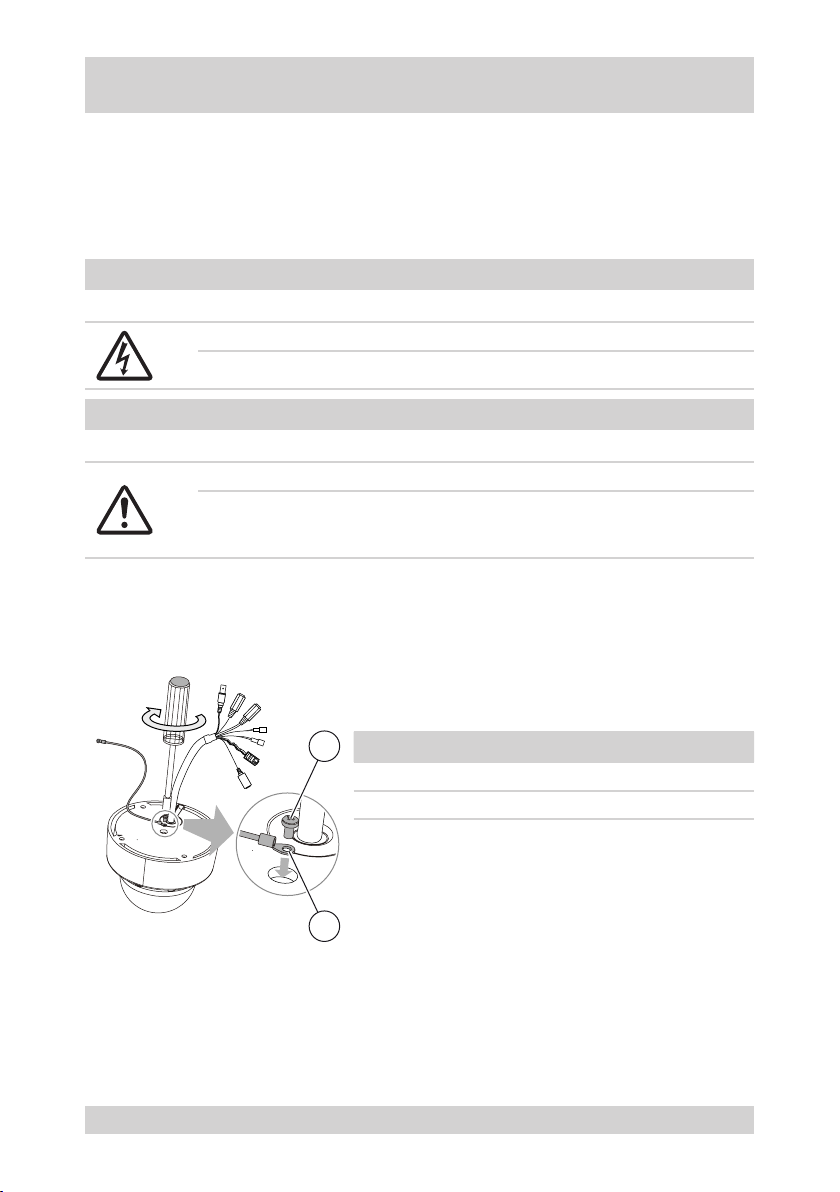
Installing the safety rope
Prior to installing the camera on a wall or ceiling you must secure the safety rope from the parts supplied on the
camera.
Danger from electric shock
The electric equipment of the camera bears the risk of a direct/indirect electric contact.
Only skilled electricians are allowed to work on the camera.
Danger from dropping objects
Improper installation can cause cameras or camera holders to drop down.
Ensure that the carrying capacity of the surface is adequate.
●
Use only suitable installation hardware.
●
Observe the Operating Instructions of the installation hardware.
●
Requirements:
Safety rope and screw from the parts supplied are available.
●
1
No. Meaning
1 Retaining screw M3x5
2 Safety rope
2
12
NTD-4101
Page 13
Installing the Camera, continued
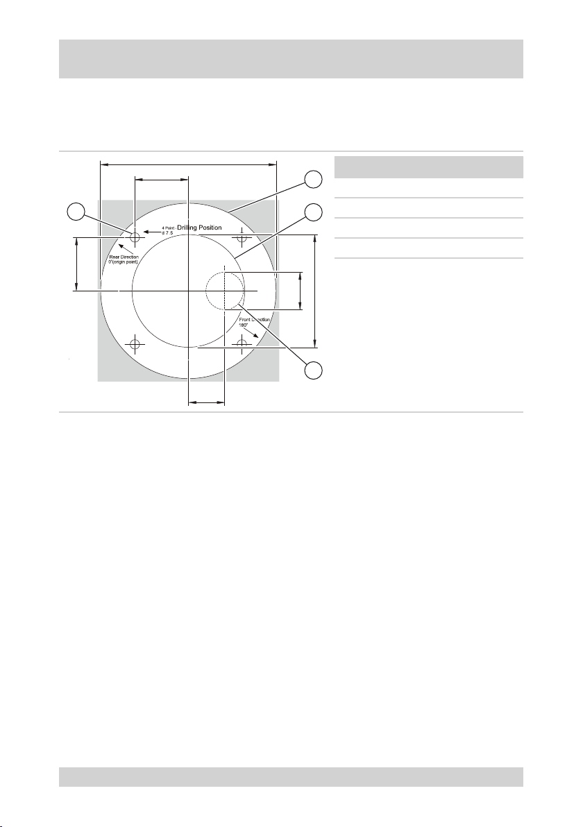
Drilling template
The enclosed drilling template permits boreholes and openings to be drilled at the correct positions.
The following gure and table show the drilling template with dimensions (in mm):
140
42.5
1
42.5
30
29
No. Meaning
2
1 Borehole Ø 7.5 mm
2 Outer edge of template
3
3 Opening in suspended ceiling
4 Opening for cable penetration
90
4
NTD-4101
13
Page 14
Installing the Camera, continued
Opening the dome cover
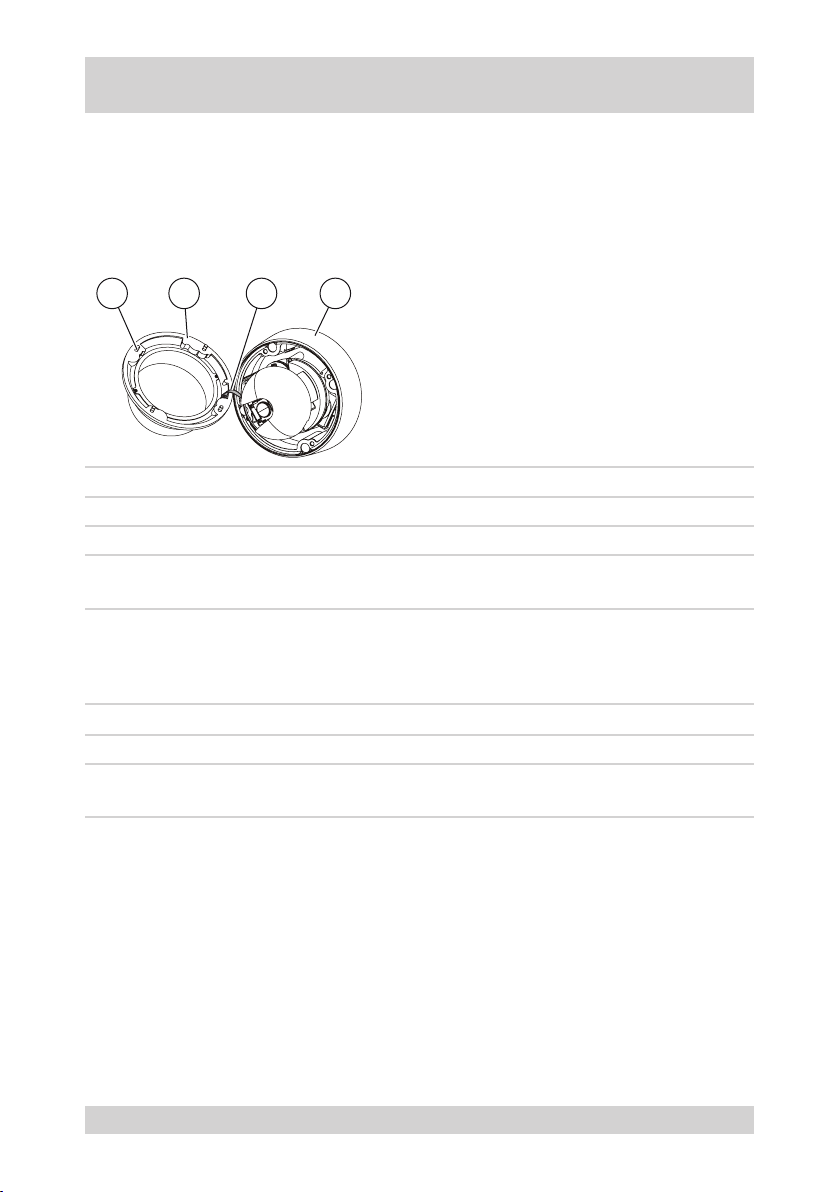
The dome cover of the camera can be opened for installation and adjustment. A exible plastic tape connects
dome cover and dome base with each other.
Requirements:
Screwdriver from parts supplied available.
●
The following gure and the table describe how the dome cover can be opened:
BA C D
Step Action
1 Release four screws (A) in the dome cover (B). Do not fully unscrew the screws.
2 Slightly lift the dome cover off the dome base (D).
3
Closing and securing the dome cover
Once installation and adjustment have been completed, you must close and secure the dome cover.
Step Action
1 Fold the dome cover (B) over the optical system onto the dome base (D).
2
Fold the dome cover at the retaining harness (C) sideways.
Result: The dome cover is open.
Tighten four screws (A) in the dome cover (B).
Result: The dome cover is closed and secured.
14
NTD-4101
Page 15
Installing the Camera, continued
Installation on ceiling or wall
This camera is suitable for
Ceiling installation, also on a suspended ceiling.
●
Wall installation.
●
Note: Suitable installation hardware see Accessories.
Requirements:
Sufciently stable installation underground.
●
Safety rope secured to the camera.
●
Connections prepared.
●
Accessories from parts supplied available.
●
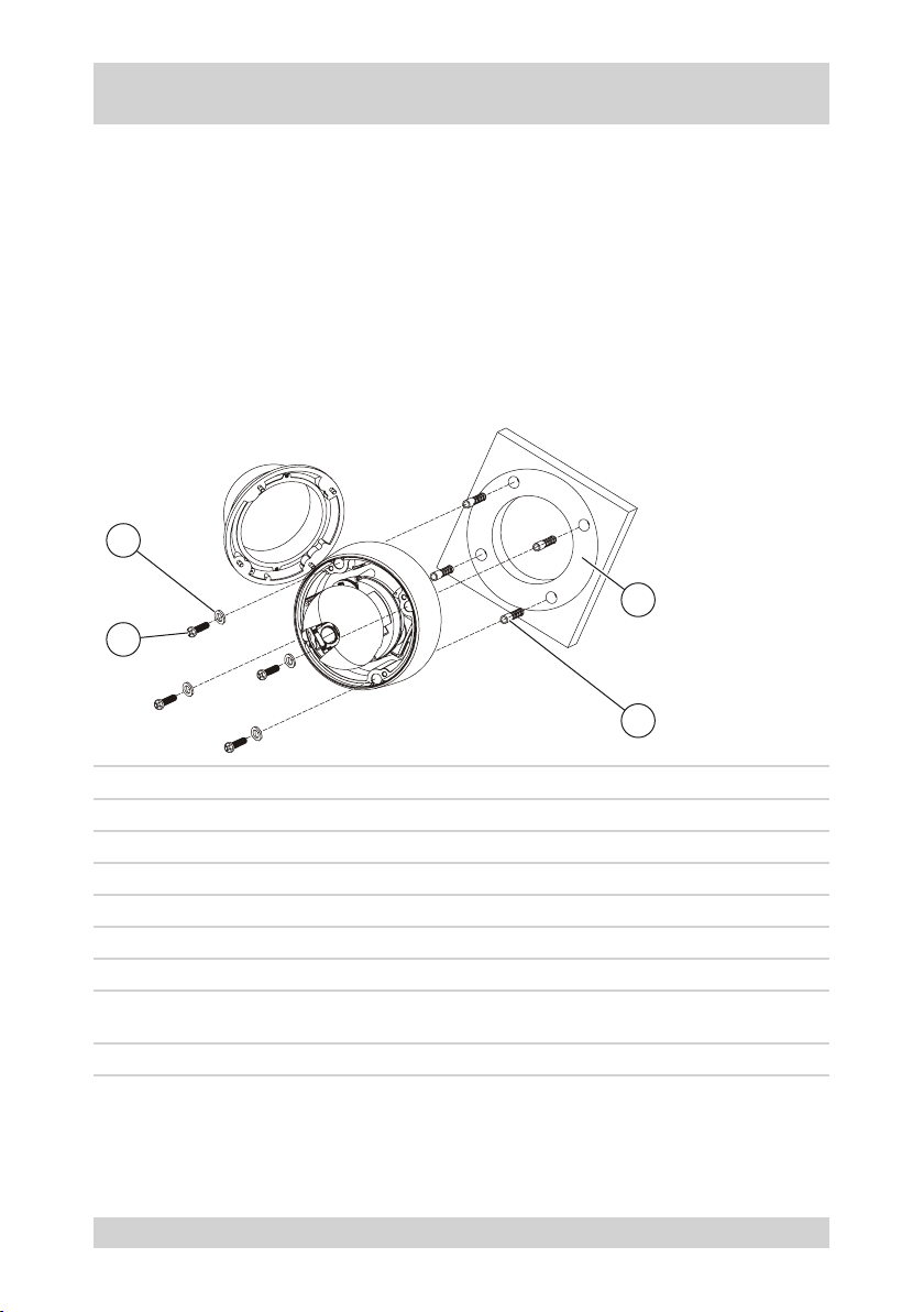
The following gure and the table describe the installation of the camera:
B
A
C
D
Step Action
1 Attach the drilling template (C) on the point of installation.
2 Make cutout and 4 boreholes according to the drilling template.
3 Insert size-8 multi-purposes wall plugs (D) into the boreholes.
4 Secure the safety rope on a bearing part.
5 Connect the camera.
6 Open the dome cover.
7
8 Close and secure the dome cover.
NTD-4101
Securely screw the dome base with 4 screws M6x35 (A) and rubber gaskets (B) in the multipurpose wall plugs (D).
15
Page 16
Installing the Camera, continued
Installing the heater kit
To enhance the temperature range of the camera you can retrot a heater kit.
Requirements:
Dome cover open.
●
Accessories „heater kit“ available.
●
The power supply rating is at least 22 W at 12 VDC for camera and heater kit.
●
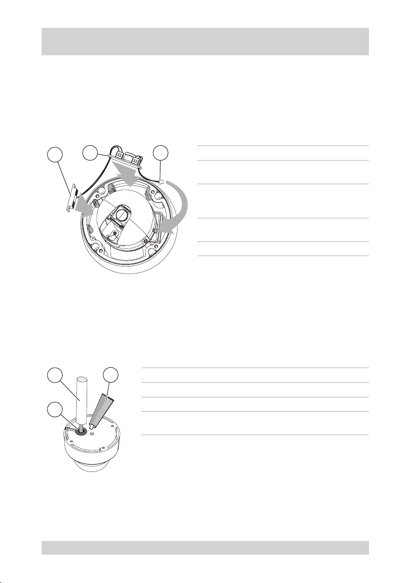
The following gure and the table describe the installation of the heater kit:
A
B C
Cable routing in the pipe
The cable outlet on the camera must be changed when the cables are routed in a pipe.
Requirements:
All cables are routed in a pipe (not in scope of delivery).
●
Silicon sealant available (not in scope of delivery).
●
The following gure and the table describe the measures to be taken for routing the cables in a pipe:
B
C
A
Step Action
1 Remove the rubber gasket (A) from the camera cable outlet.
2 Route the pipe (B) over the cables to the camera.
3
Step Action
Insert the heater element (A); the cooling ns
1
point towards the camera inside.
Insert the printed circuit board (B); the
2
soldering side points towards the camera
inside.
Insert the plug (C) into the socket (J701) of the
3
PTZ board.
4 Close and secure the dome cover.
Sealing with silicon sealant around the pipe (C) replaces the
removed rubber gasket.
16
NTD-4101
Page 17
Connecting the Camera
Connecting the power supply
The power supply connection of this camera is suitable for a 12 VDC power supply.
Requirements:
Use only certied/listed power supply units of protection class 2.
●
The power supply unit must be able to supply 12 VDC with at least 12 W.
●
Danger from electric shock
DANGER!
Video connection
The video output of this camera supplies a video signal of 1.0 Vp-p / 75 ohms. The video signal is transferred
via a twisted-pair (UTP)
Note: The metal of the BNC connector must not be in contact with any other metal part.
Audio connection input
The audio input of this camera is suitable for receiving an audio signal of microphone level via an asymmetrical
line.
Audio connection output
The audio output of this camera supplies an audio signal of line level via an asymmetrical line.
Network connection
The network connection of this camera is suitable for transmitting signals and for controlling the camera via a
network.
Requirements:
Use a standard RJ-45 crossover LAN cable for setup (IP assignment).
●
Use a standard RJ-45 LAN cable for video operation.
●
Danger from electric shock
The electric equipment of the camera bears the risk of a direct/indirect electric contact.
Only skilled electricians are allowed to work on the camera.
Alarm connection input
The alarm input of this camera is suitable for mechanical and electrical alarm contacts.
Requirements:
The cable ends must be insulated after connection, even when they are unused.
●
The earth connection of alarm input and/or alarm output are connected to GND.
●
RS-485 connection
The RS-485 connection of this camera is suitable for an RS-485 interface with baud rate 9600 bps.
Requirements:
The cable ends must be insulated after connection, even when they are unused.
●
Total communication cable length: max. 1200 m.
●
NTD-4101
17
Page 18
Camera Settings
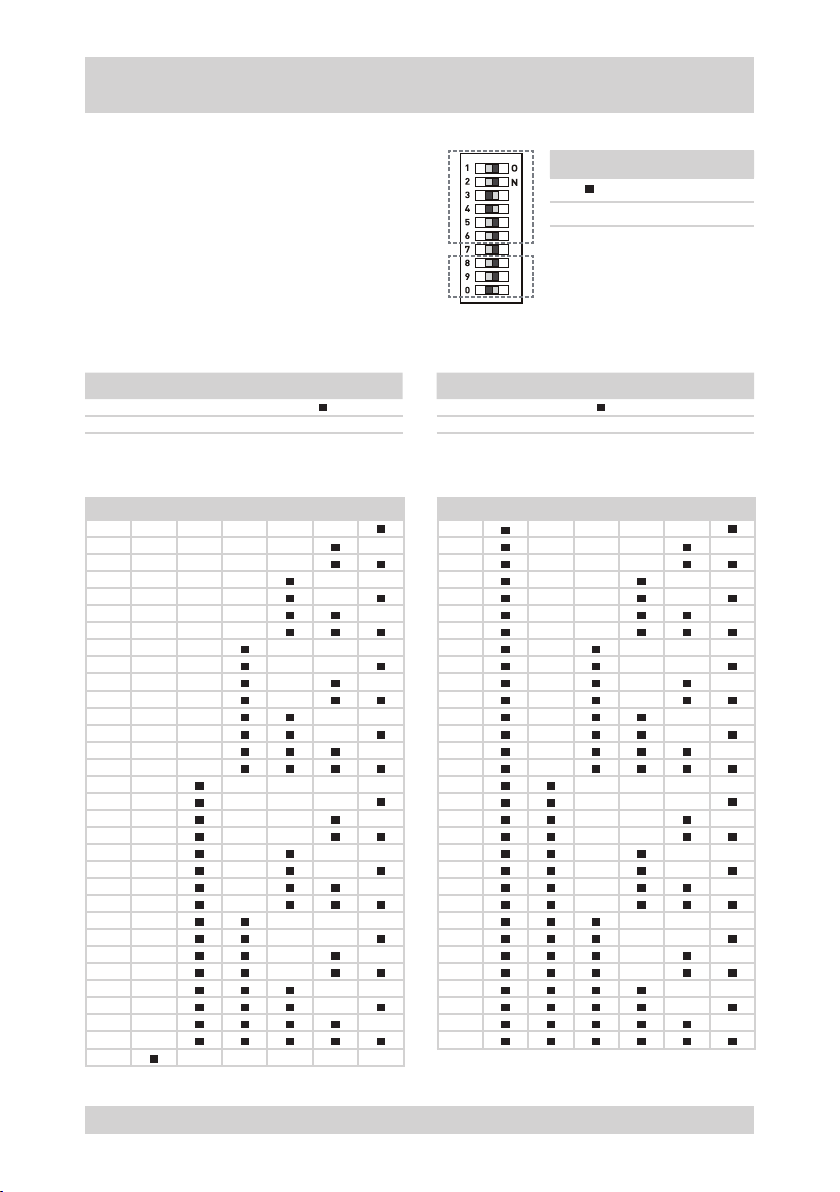
The settings on the camera are made via DIP switches.
Requirements:
Camera separated from the power supply.
●
DIP switches accessible.
●
Network connection conguration known.
●
Selecting the colour standard Selecting the control protocol
Requirement: Colour standard known. Requirement: Control protocol known.
Colour standard DIP No. 8
NTSC
PAL -
Protocol DIP No. 9 DIP No. 0
Fastrax-II -
PELCO-D - -
Setting the ID address
The following table shows the settings of the DIP switches for networks:
6 5 4 3 2 1
ID
- - - - -
1
- - - - -
2
- - - -
3
- - - - -
4
- - - -
5
- - - -
6
- - -
7
- - - - -
8
- - - -
9
- - - -
10
- - -
11
- - - -
12
- - -
13
- - -
14
- -
15
- - - - -
16
- - - -
17
- - - -
18
- - -
19
- - - -
20
21
- - -
22
- -
23
- - - -
24
- - -
25
- -
26
- -
27
- - -
28
29
- -
30
-
31
32
- -
- - - - -
-
6 5 4 3 2 1
ID
33
34
35
36
37
38
39
40
41
42
43
44
45
46
47
48
49
50
51
52
53
54
55
56
57
58
59
60
61
62
63
Icon Meaning
ON
- OFF
- - - -
- - - -
- - -
- - - -
- - -
- - -
- -
- - - -
- - -
- - -
- -
- - -
- -
- -
-
- - - -
- - -
- - -
- -
- - -
- -
- -
-
- - -
- -
- -
-
- -
-
-
18
NTD-4101
Page 19

Camera Settings, continued
Multiplexer in the network
Systematic address assignments avoid address conicts in the network when several cameras are used via
multiplexers.
The ID address depends on
●
the number of multiplexers.
●
the camera input at the related multiplexer.
The ID address is calculated as:
Camera ID = 16 x (multiplexer ID - 1) + camera input
Examples
Multiplexer ID Camera input Calculation Camera ID
1 4 = 16 x (1 - 1) + 4 = 0 + 4 4
1 13 = 16 x (1 - 1) + 13 = 0 + 13 13
2 1 = 16 x (2 - 1) + 1 = 16 + 1 17
3 11 = 16 x (3 - 1) + 11 = 32 + 11 43
NTD-4101
19
Page 20
Operation via system keypad
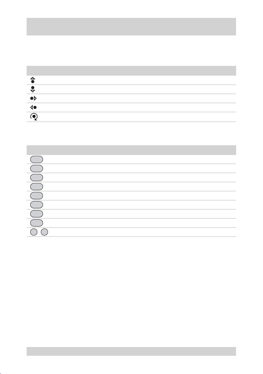
The camera can be operated via a system keypad. Suitable system keypads see accessories.
Note: Observe the instructions in the product documentation of the system keypad.
Joystick menu functions
Joystick Menu function
Next higher menu function
Next lower menu function
Next value or mode
Previous value or mode
Joystick rotation
Keypad menu functions
Button Menu function
MENU
ESC
CTRL
PGM
PRST
TOUR
SCAN
ALRM
0
Invoke „MAIN MENU“
Cancel entries and return to the previous menu
Enable joystick for camera function
Allocate presets to numeric keys
Invoke preset
Invoke camera movement
Invoke automatic scanning
Reset alarm
9
Numeric keys
...
20
NTD-4101
Page 21
Camera menu operation
Invoking menu settings
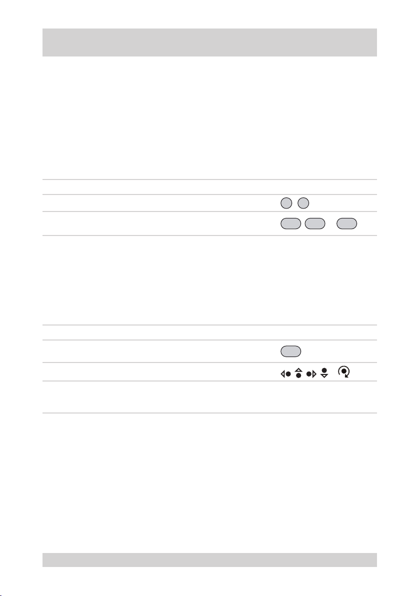
The following settings saved in the camera menu can directly be invoked via the system keypad:
●
Preset (PRESET)
Camera movement (TOUR)
●
Automatic scanning (AUTO SCAN)
●
Requirements:
●
System keypad connected to RS-485 interface of the camera.
●
Settings saved in the camera menu.
The following table describes the invocation of saved settings:
Step Action Operation
0
1 Enter the number of the saved function.
2
Select the function.
Result: The saved function is executed.
Controlling the camera during menu operation
During the PRESET menu, you can control the camera in order to enter several presets in succession.
Requirements:
PRESET menu in Preset menu item active
●
The following table describes the camera control during menu operation:
Step Action Operation
1
2 Make PTZ settings.
3
Press and hold the CTRL button.
Result: The text „CONTROL“ appears on the OSD.
Release CTRL button.
Result: The text „CONTROL“ disappears from the OSD. The
settings can be saved as presets.
9
...
PRST, TOUR
CTRL
, , , or
PRESET MENU
, or
SCAN
NTD-4101
21
Page 22
Camera menu operation, continued
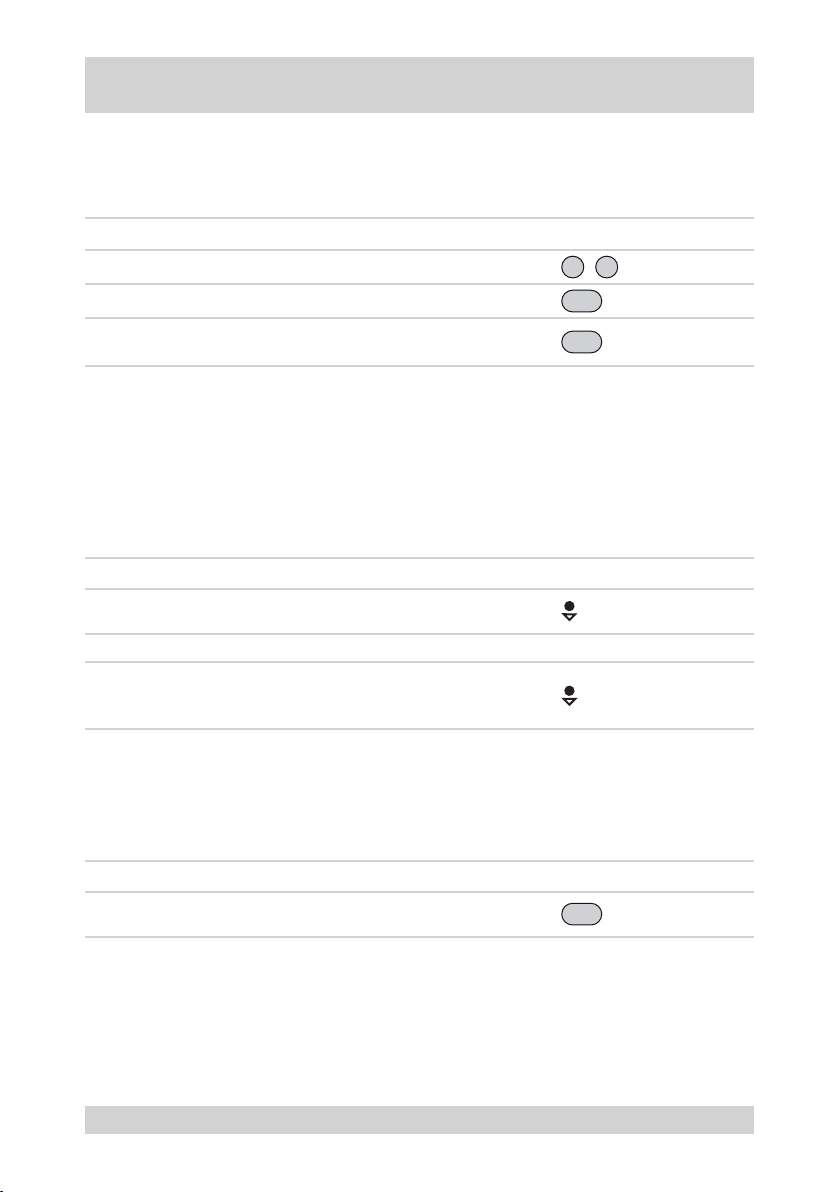
Saving presets via the system keypad
The current PTZ settings can be saved as presets via the system keypad.
The following table describes the saving of presets via the system keypad:
Step Action Operation
0
PGM
PRST
9
...
1 Enter the number of the preset.
2 Press the PGM button.
3
Press the PRST button.
Result: The current PTZ settings are saved as presets.
Camera movement with enabled automatic image reversal
The automatic image reversal rotates the camera through 180°. This permits the camera movement to be
continued beyond the vertical position.
Requirements:
Automatic image reversal enabled
●
The following table describes the operation with automatic image reversal:
Step Action Operation
1
2 Release the joystick briey. -
2
Camera movement until vertical inclination = 90°.
Result: The camera stops and looks vertically downward.
Continue the camera movement.
Result: The camera rotates through 180°, the camera movement is continued.
Resetting alarm
An activated alarm can be terminated by resetting it via the system keypad.
The following table describes how an alarm is reset.
Step Action Operation
1
22
Reset alarm.
Result: Alarm function reset.
ALRM
NTD-4101
Page 23

Camera menu operation, continued
Operation via web browser
The integrated web browser enables camera and menu to be operated without system keypad.
Requirements:
Camera and PC are connected via a standard RJ-45 LAN cable in a network-compatible way.
●
Web browser (e.g. Internet Explorer) installed in the PC.
●
Current version of ActiveX/HVC installed in the PC.
●
IP address of the camera is known.
●
Note: The integrated help function provides comprehensive information about the operation of the web
browser.
NTD-4101
23
Page 24
Camera Menu Overview
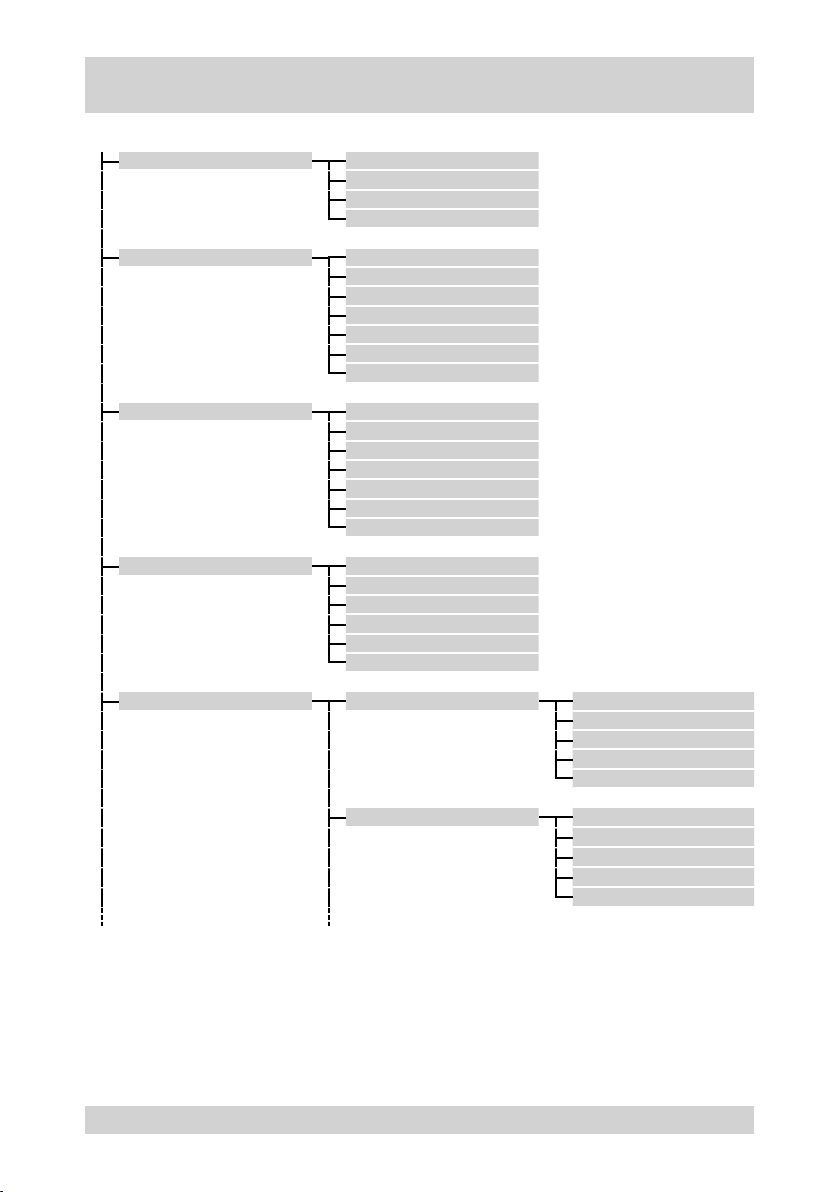
The following gure shows the structure of the menu tree, accessible via the menu navigation of the camera:
PRESET NUMBER
TITLE
SAVE AND EXIT
EXIT
TOUR TOUR
AUTO SCAN SCAN
ALARM INPUT
CAMERA SETUP FOCUS CONTROL MODE
TITLE
DWELL TIME
= = = ...
DELETE DATA
SAVE AND EXIT
EXIT
TITLE
START POINT
TILT AND ZOOM
END POINT
SAVE AND EXIT
EXIT
OPTION
PRESET
DWELL TIME
SAVE AND EXIT
EXIT
DISTANCE
DIGITAL ZOOM
SAVE AND EXIT
EXIT
WB CONTROL MODE
R GAIN
B GAIN
SAVE AND EXIT
EXIT
24
NTD-4101
Page 25
Camera Menu Overview, continued
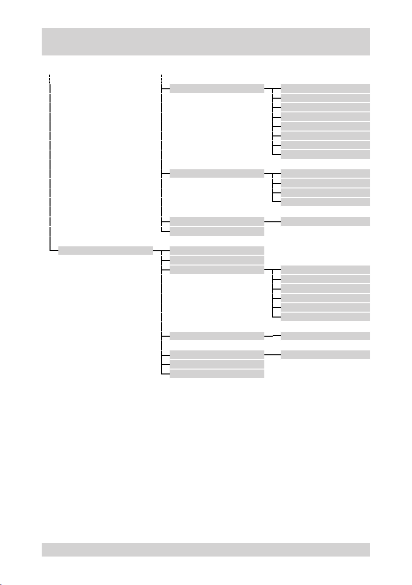
The following gure shows the structure of the menu tree, accessible via the menu navigation of the camera:
AE CONTROL MODE
PICTURE MIRROR
INITIALIZE CAMERA YES or NO
EXIT
DOME SETUP OSD DISPLAY
TILT AUTO FLIP
HOME FUNCTION MODE
INITIALIZE DOME YES or NO
DOME INFORMATION VERSION: x.y.z
SAVE AND EXIT
EXIT
IRIS
GAIN
SHUTTER
BRIGHT
BACK LIGHT
SAVE AND EXIT
EXIT
SHARPNESS
SAVE AND EXIT
EXIT
FUNCTION TYPE
FUNCTION NUMBER
DWELL TIME
SAVE AND EXIT
EXIT
NTD-4101
25
Page 26

Menu Descriptions – Camera Menu
The camera menu has the following submenus:
PRESET
The following items are dened in the „PRESET MENU“ menu:
PRESET
TOUR (camera movement)
TOUR
AUTO SCAN (automatic scanning)
AUTO SCAN
ALARM
ALARM
The PTZ settings of the presets
●
The designations of the presets
●
The following items are dened in the „TOUR MENU“ menu:
The camera movements along presets
●
The dwell time
●
The designation of the camera movement
●
The following items are dened in the „AUTO SCAN MENU“ menu:
The start and end points of the automatic camera movements
●
The PTZ settings of the camera movement
●
The designation of the camera movement
●
The following items are dened in the „ALARM“ menu:
The type of the alarm input
●
The alarm options
●
The reaction of the camera to alarm activation
●
CAMERA SETUP
The following items are dened in the „CAMERA SETUP MENU“ menu:
●
CAMERA SETUP
DOME SETUP
DOME SETUP
26
●
●
●
●
The following items are dened in the „DOME SETUP MENU“ menu:
●
●
●
The focus settings
The white balance settings (WB)
The settings for automatic exposure control (AE)
The settings for the video image
Resetting the camera to the delivery state
The settings for the OSD
The settings for the home function
Resetting the dome part to the delivery state
NTD-4101
Page 27
Camera menu
PRESET (xed positions)
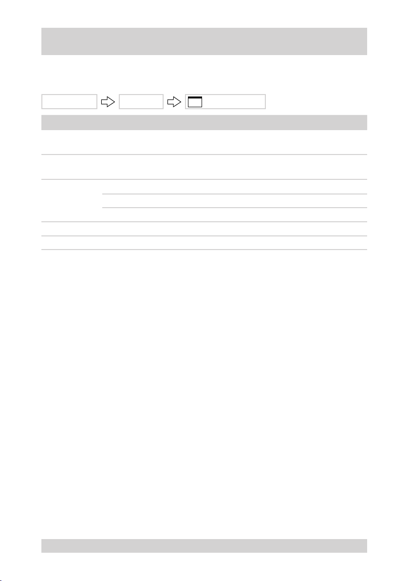
The xed positions are dened in the „PRESET MENU“.
MAIN MENU PRESET PRESET MENU
Term Meaning
NUMBER
TITLE
= = = ...
SAVE AND EXIT Save the entries and return to the „MAIN MENU“
EXIT Back to the „MAIN MENU“
Number of the preset:
1 ... 60
Set the designation of the preset:
Max. 10 letters or gures in any combination
Status display of the presets:
= Preset not assigned
* Preset assigned
NTD-4101
27
Page 28
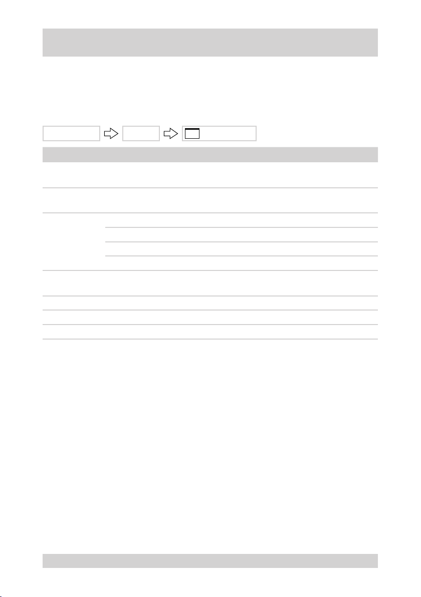
Camera menu, continued
TOUR (camera movements)
The following items are dened in the „TOUR MENU“ menu:
The camera movement along presets
●
The dwell time
●
The designation of the camera movement
●
MAIN MENU TOUR TOUR MENU
Term Meaning
TOUR
TITLE
DWELL TIME
== == ...
DELETE DATA Delete entries of the selected camera movement
SAVE AND EXIT Save the entries and return to the „MAIN MENU“
EXIT Back to the „MAIN MENU“
Number of the camera movement:
1 ... 4
Set the designation of the camera movement:
Max. 10 letters or gures in any combination
Set the dwell time at the presets:
5 s Min. dwell time
5 s Factory setting
99 s Max. dwell time
Input of the presets of the camera movement:
Up to 16 presets per tour
28
NTD-4101
Page 29
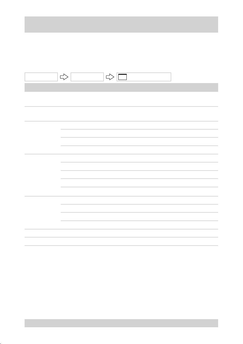
Camera menu, continued
AUTO SCAN (automatic scanning)
The following items are dened in the „AUTO SCAN MENU“ menu:
The start and end points of the camera movement for automatic scanning
●
The PTZ settings of the automatic scanning.
●
The designation of the camera movement
●
MAIN MENU AUTO SCAN AUTO SCAN MENU
Term Meaning
SCAN
TITLE
START POINT
TILT AND ZOOM
END POINT
SAVE AND EXIT Save the entries and return to the „MAIN MENU“
EXIT Back to the „MAIN MENU“
Number of the camera movement:
1 ... 4
Set the designation of the camera movement:
Max. 10 letters or gures in any combination
Set the horizontal start angle:
0.0° Min. horizontal start angle
0.0° Factory setting
360.0°
Select inclination and zoom:
0.0° Min. inclination
0.0° Factory setting
90.0° Max. inclination
Note: No display of the zoom value, setting by image contents.
Set the horizontal end angle:
0.0° Min. horizontal end angle
0.0° Factory setting
360.0°
Max. horizontal start angle
Max. horizontal end angle
NTD-4101
29
Page 30
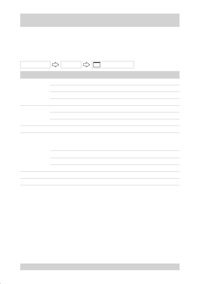
Camera menu, continued
ALARM
The following items are dened in the „ALARM“ menu:
The type of the alarm input
●
The alarm options
●
The reaction of the camera to alarm activation
●
MAIN MENU ALARM ALARM MENU
Term Meaning
Set the type of the alarm input:
INPUT
OPTION
PRESET Select a preset set in the „PRESET MENU“
DWELL TIME
SAVE AND EXIT Save the entries and return to the „MAIN MENU“
EXIT Back to the „MAIN MENU“
OFF Alarm input OFF
NC NC contact as alarm contact
NO
Set the options after alarm activation:
MOMENTARY Continuous alarm
TIME OUT Return to the previous function after dwell time
Delay for alarm
Note: The setup mode depends on the following settings:
OPTION = TIME OUT
5 s Min. dwell time
5 s Factory setting
99 s Max. dwell time
NO contact as alarm contact
30
NTD-4101
Page 31
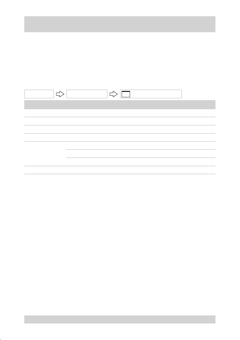
Camera menu, continued
CAMERA SETUP
The following items are dened in the „CAMERA SETUP“ menu:
●
The focus settings
The settings of the digital zoom
●
The white balance settings
●
●
The settings for automatic exposure control.
●
The video image settings
●
Resetting the camera to the delivery state
MAIN MENU CAMERA SETUP CAMERA SETUP MENU
Term Meaning
FOCUS CONTROL Set focus and digital zoom >>
WB CONTROL White balance settings >>
AE CONTROL Set automatic exposure control >>
PICTURE Video image settings >>
Reset camera part to delivery state:
INITIALIZE CAMERA
EXIT Back to the „MAIN MENU“
NO Return to „CAMERA SETUP MENU“
YES Reset camera part to delivery state
NTD-4101
31
Page 32
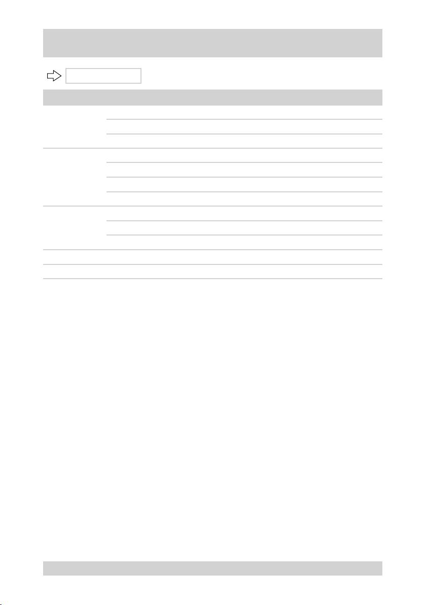
Camera menu, continued
FOCUS CONTROL
Term Meaning
Type of focussing
MODE
DISTANCE
DIGITAL ZOOM
SAVE AND EXIT Save the entries and return to the „CAMERA SETUP MENU“
EXIT Return to „CAMERA SETUP MENU“
AUTO Autofocus
MANUAL Manual focus
Adjusting the focus of the lens:
0.1M Min. focus
0.1M Factory setting
6.0M
Set digital zoom:
OFF Optical zoom only
ON Digital and optical zoom
Max. focus
32
NTD-4101
Page 33
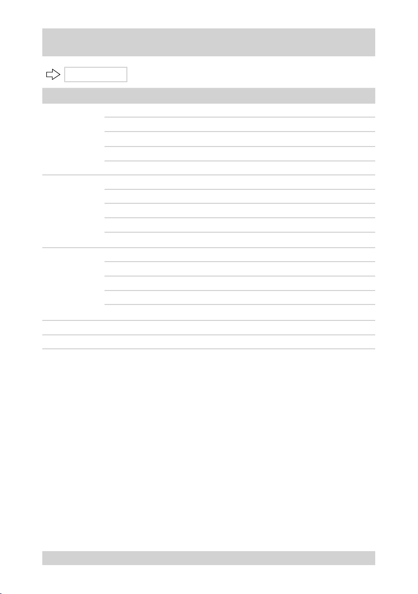
Camera menu, continued
WB CONTROL
Term Meaning
Modes for white balance:
AUTO Automatic white control
MODE
R GAIN
B GAIN
SAVE AND EXIT Save the entries and return to the „CAMERA SETUP MENU“
EXIT Return to „CAMERA SETUP MENU“
INDOOR White balance for indoor areas
OUTDOOR White balance for outdoor areas
MANUAL Manual white balance
Red intensication:
0 Min. intensication
39
255 Max. intensication
Note: Only possible in conjunction with „MANUAL“ mode.
Blue intensication:
0 Min. intensication
92 Factory setting
255 Max. intensication
Note: Only possible in conjunction with „MANUAL“ mode.
Factory setting
NTD-4101
33
Page 34
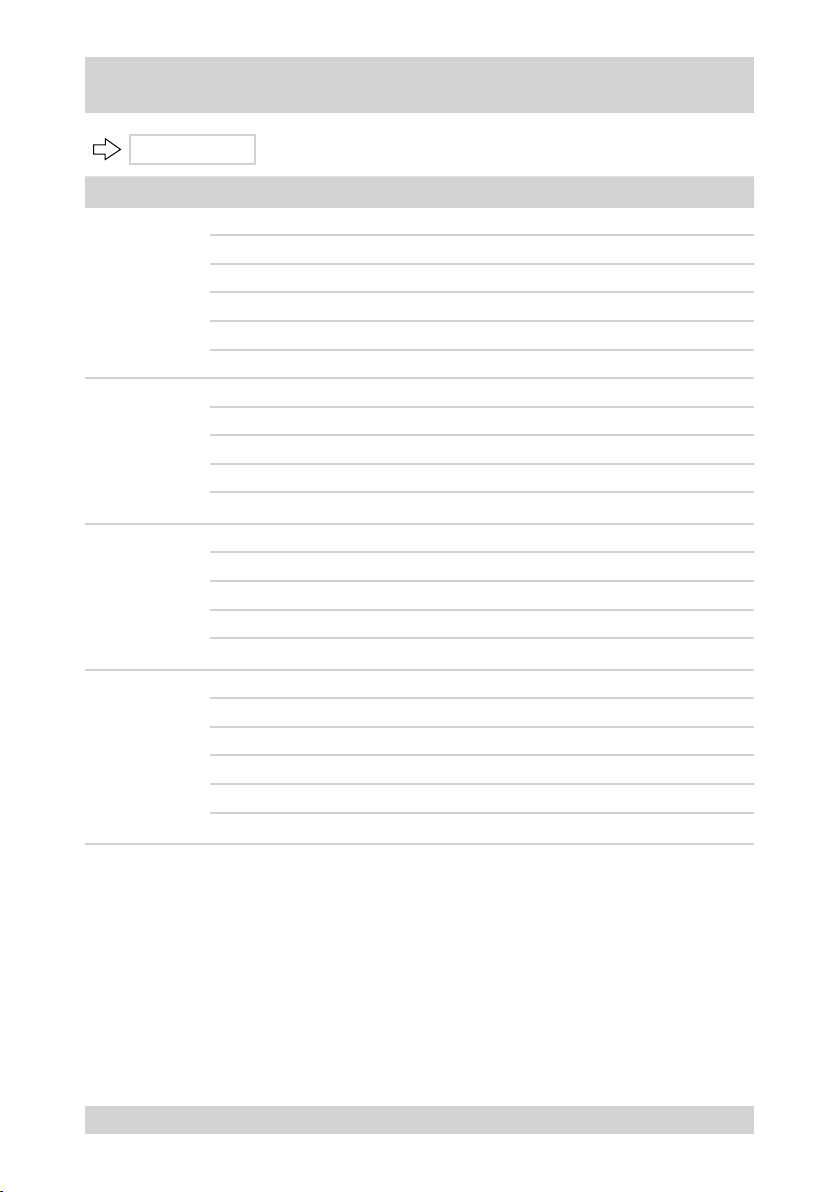
Camera menu, continued
AE CONTROL
Term Meaning
Modes for automatic exposure control:
AUTO AE control
MODE
IRIS
GAIN
SHUTTER
SHUTTER PRI Priority - adjusting the shutter speed
IRIS PRI Priority - iris setting
MANUAL Manual exposure control
FLICKERLESS Image ickering suppression
Iris adjustment:
CLOSE No iris
F1.8 Factory setting
F22
Note: Only possible in conjunction with „MANUAL“ mode or „IRIS PRI“.
Gain setting:
0 Min. intensication
0 Factory setting
30
Note: Only possible in conjunction with „MANUAL“ mode.
Shutter speed setting:
100 Min. speed
NORMAL Factory setting in „SHUTTER PRI“ or „MANUAL“ mode.
120
10000
Note: Not possible in conjunction with „AUTO“ mode or „IRIS PRI“.
Max. iris
Max. intensication
Factory setting in „FLICKERLESS“ mode
Max. speed
34
NTD-4101
Page 35
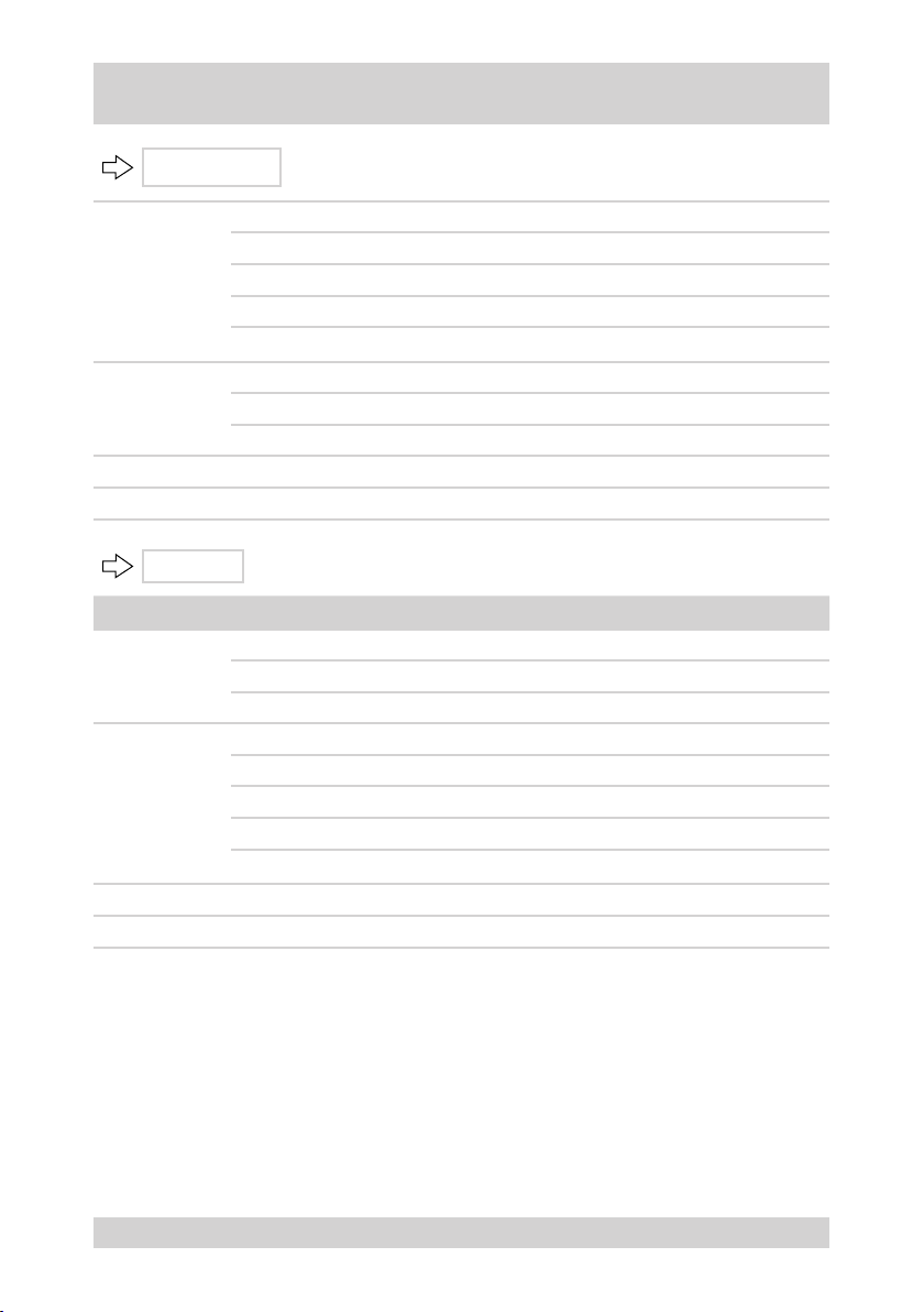
Camera menu, continued
AE CONTROL
BRIGHT
BACKLIGHT
SAVE AND EXIT Save the entries and return to the „CAMERA SETUP MENU“
EXIT Return to „CAMERA SETUP MENU“
PICTURE
Term Meaning
MIRROR
SHARPNESS
SAVE AND EXIT Save the entries and return to the „CAMERA SETUP MENU“
EXIT Return to „CAMERA SETUP MENU“
, continued
Brightness setting:
0 Min. brightness
30
90 Max. brightness
Note: Not possible in conjunction with „MANUAL“ mode.
Back light compensation setting:
OFF Deactivate back light compensation
ON Activate back light compensation
Mirroring the camera image:
OFF No mirroring
ON Horizontal mirroring
Manual sharpness adjustment of the camera image:
00 Min. contour sharpness
08 Factory setting
15 Max. contour sharpness
Note: Only possible in conjunction with „MANUAL“ mode.
Factory setting
NTD-4101
35
Page 36
Camera menu, continued
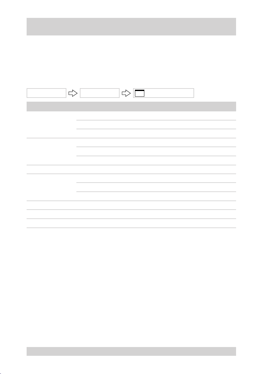
DOME-SETUP
The following items are dened in the „DOME SETUP MENU“ menu:
Display of the camera settings on the monitor
●
The settings for automatic image reversal
●
The settings of the park position.
●
Resetting the dome part to the delivery state
●
MAIN MENU DOME SETUP DOME SETUP MENU
Term Meaning
Set OSD display:
OSD DISPLAY
TILT AUTO FLIP
HOME FUNCTION Home function setting >>
INITIALIZE DOME
DOME INFORMATION Display software version
SAVE AND EXIT Save the entries and return to the „MAIN MENU“
EXIT Back to the „MAIN MENU“
ON OSD displayed
OFF OSD not displayed
Automatic image reversal when inclination > 90°:
ON Activate automatic image reversal
OFF Deactivate automatic image reversal
Reset dome part to delivery state:
NO Return to „DOME SETUP MENU“
YES Reset dome part to delivery state
36
NTD-4101
Page 37
Camera menu, continued
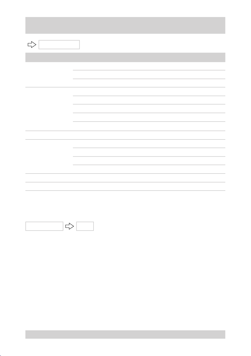
HOME FUNCTION
Term Meaning
Home function setting:
MODE
FUNCTION TYPE
FUNCTION NUMBER Select the number of the function selected under „FUNCTION TYPE“
DWELL TIME
SAVE AND EXIT Save the entries and return to the „DOME SETUP MENU“
EXIT Return to „DOME SETUP MENU“
OFF Home function disabled
ON Home function enabled
Select function:
PRESET Preset
TOUR Camera movement
AUTO SCAN Automatic scanning
Note: Only possible in conjunction with home function „ON“.
Set the dwell time:
5 s Min. dwell time
5 s Factory setting
600 s Max. dwell time
EXIT
The main menu is exited with „EXIT“.
MAIN MENU EXIT
NTD-4101
37
Page 38
Setting up Network Connectivity
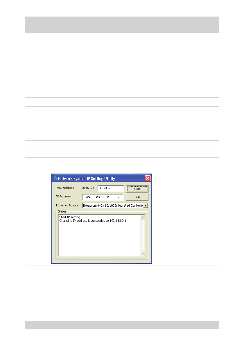
Allocating or changing the camera IP address
Requirements:
PC with xed IP address available.
●
In WINDOWS XP, the rewall is disabled during IP allocation.
●
CD with viewer software (NT-Manager), setup software and client software available.
●
Camera and PC are connected via a standard RJ-45 crossover cable in a network-compatible way.
●
MAC address of the camera is known.
●
Free IP address for camera is known.
●
Name of the employed Ethernet adapter is known.
●
Step Action Menu path/menu item
1 Execute and/or save setup software and client software
from the CD.
Result: The „Network System IP Setting Utility“ window is
opened.
2 Complete the MAC address of the camera. MAC address
3 Enter the IP address of the camera. IP address
4 Select the Ethernet adapter of the PC. Ethernet adapter
5 Log on the camera in the network.
Result: The IP address is allocated to the camera.
IP setting utility
START
38
NTD-4101
Page 39
Camera Control via NT-Manager
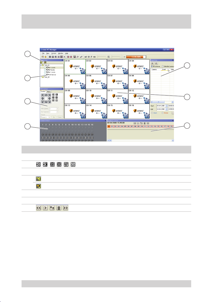
NT-Manager main menu
The following gure and the table describe the main menu of the NT-Manager:
4
3
5
2
1
No. Designation Function
Display
1
2
3 Display Camera list
4
5
6 Display Monitoring image
7 Playback control
Display
Camera status
PTZ control
Add group
Add camera
Search list
Additional information
The complete software description of the NT-Manager can be found in the Help function of the NT-Manager
software.
6
7
NTD-4101
39
Page 40
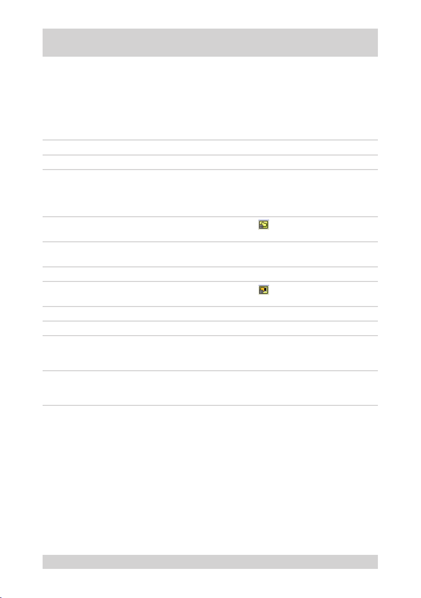
Camera Control via NT-Manager, continued
Logging on the camera in the network
Requirements:
PC with xed IP address available.
●
CD with viewer software (NT-Manager), setup software and client software available.
●
Camera and PC are connected via a standard RJ-45 LAN cable in a network-compatible way.
●
IP address of the camera is known.
●
Step Action Menu path/menu item
1
2 Open the Viewer software.
3 Add new group.
4 Enter the name of the new group, and conrm it.
5
6 Add the new camera to the group.
7
8
9 Register the camera.
10 Select the camera from the camera list, and drag it to
Install Viewer software from the CD.
User name: admin
Password: admin
Result: The Viewer software (NT-Manager) is opened.
Result: The „Add new group„ window is opened.
Result: The new group is added to the camera list.
Select the group in the camera list.
Result: The „Add a new camera“ window appears.
Enter the name of the new camera.
Enter the IP address of the camera.
Result: The new camera is added to the camera list,
and integrated.
a channel on the screen (Drag&Drop).
Result: The camera image appears on the screen.
-
-
Add
-
-
Host address
Add
-
40
NTD-4101
Page 41
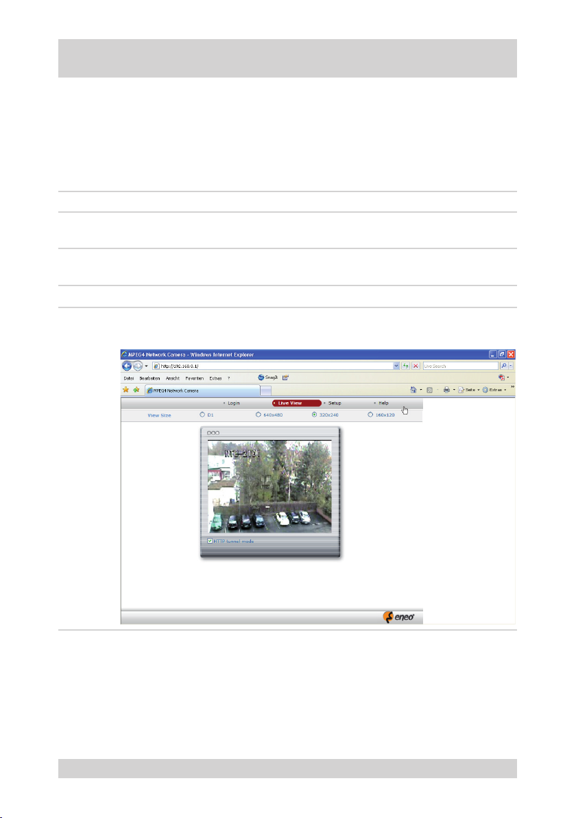
Camera Control via Web Browser
Connecting camera with web browser
Requirements:
Camera and PC are connected via a standard RJ-45 LAN cable in a network-compatible way.
●
Web browser (e.g. Internet Explorer) installed in the PC.
●
Current version of ActiveX/HVC installed in the PC.
●
IP address of the camera is known.
●
Step Action
1 Open the web browser.
Note: A separate web browser window must be opened for each camera.
2 Enter the IP address of the camera into the address line of the web browser.
Example: http://192.168.0.2
3
4 Select login.
Enter user name (admin) and password (no entry).
Result: The camera is connected with the web browser.
NTD-4101
41
Page 42
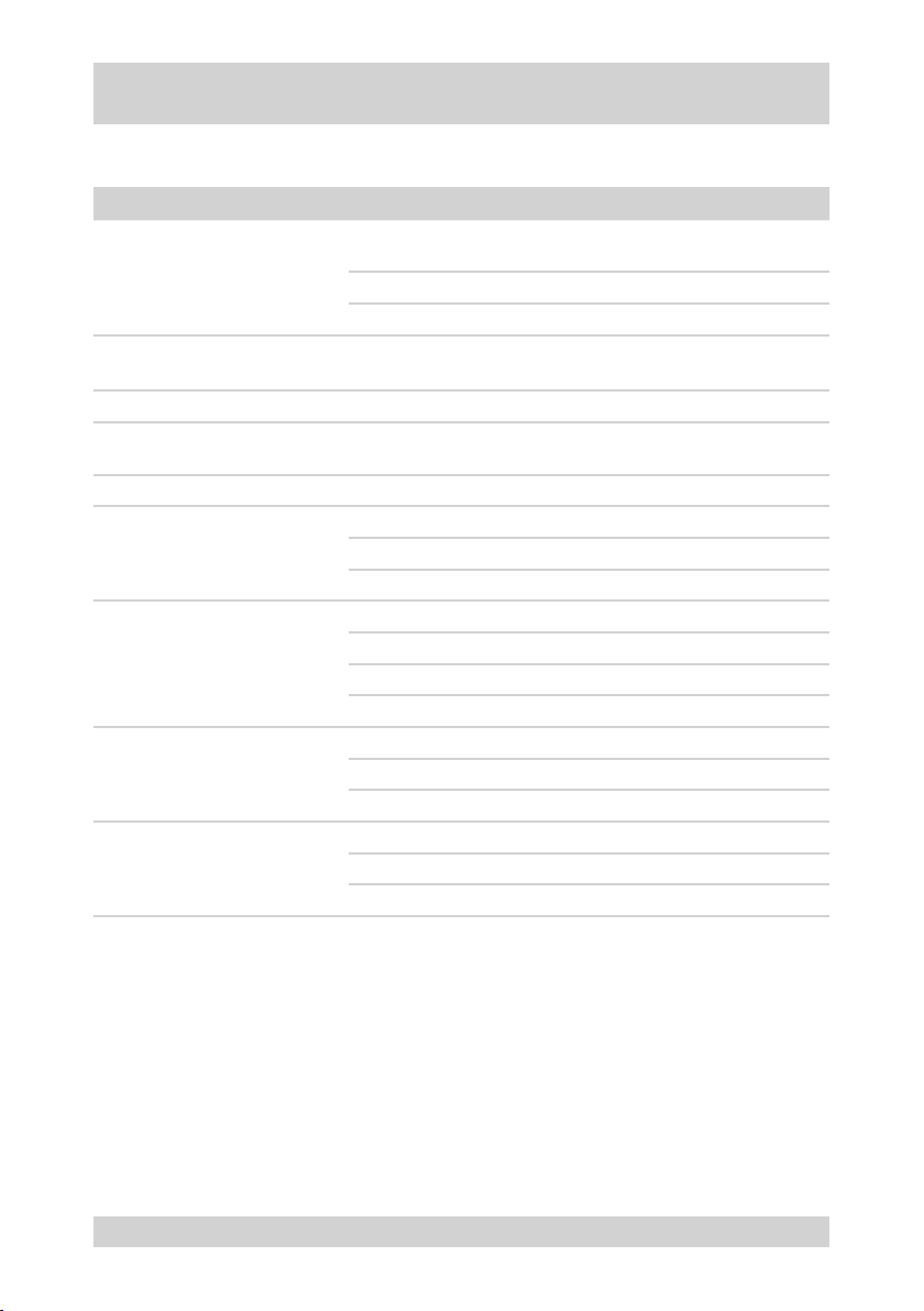
Possible Errors and Solutions
The following table describes potential errors and possible solutions:
Note: Please refer to www.videor.com for further information
Error Possible solution
Check the power supply of the camera and of the entire installation.
No video image visible
Video image exists, but control is
not possible.
Video image too dark Adjust the lens iris properly.
Signal interruption at short intervals
Frame rate decreases Reduce the settings of resolution, compression and frame rate.
IP allocation failed
Automatic white control does not
work properly
Control via RS-485 disturbed
Keypad operation disturbed
The ready indicator of the camera must be ON.
Check the video cable of the camera. Connect it properly if necessary.
Open the lens iris.
Briey interrupt the power supply of the camera or the entire system
(reset).
Check the network workload; contact system administrator if
necessary.
Disable WINDOWS XP rewall during IP allocation.
Use a standard RJ-45 Crossover LAN cable.
Allocate a xed IP address to the PC.
Select „AUTO“ in the camera menu.
Avoid a dark object environment.
Avoid strong changes in the lighting.
Check the colour temperature of the object.
Terminate the devices at the physical end of the RS-485 line.
Total communication cable length: max. 1200 m.
Check ID addresses.
Repeat log on at keypad.
Check the connections.
Check the peripherals.
42
NTD-4101
Page 43

Specications NTD-4101
Model NTD-4101
EDP No. 93155
System Colour
Video standard PAL
Sensor size 1/4“
Imager CCD, Sony Super HAD Interline Transfer
Synchronization Internal
External synchronization No
Signal-to-noise ratio 48 dB (AGC OFF)
Light sensitivity
(at 50% video signal)
Horizontal resolution 430 TVL
Automatic gain control (AGC) Automatic up to max. 30 dB (switchable)
Linear electronic shutter (ESC) 1/50 ~ 1/10,000 s, automatic and manual
Image integration No
Aperture correction (APC) Horizontal and vertical
White balance Modes: Manual, automatic, indoors, outdoors
Back light compensation BLC
IR cut lter Yes, xed
Motion detector Yes
Text display Available
Menu driven set-up On/off switchable
Menu languages English
Image setup Colour, brightness and contrast (via network)
Video outputs (type) FBAS
Video outputs 1 Vp-p, FBAS 75 ohms
Audio support No
Alarm input 1
Alarm inputs Yes
Alarm handling
Internal buffer Yes
System requirements
Compression method MPEG4, part 2 (ISO/IEC 14496-2), proles SP and ASP
Image resolution max. 720 x 576 pixels
0.85 Lux
Via built-in motion detection, sensitivity and changeover setting,
E-mail transmission
Windows 2000/XP, Intel Pentium IV 2 GHz or higher,
512 MB RAM or more,
hard disk min. 80 GB (depends on recording requirements).
NTD-4101
43
Page 44

Specications NTD-4101, continued
Model NTD-4101
Resolution Network: 720 x 576 (D1), 640 x 480, 320 x 240, 160 x 120 pixels
Image transfer rate max. 50 elds/s
Frame rate Max. 25 ips at 720 x 576 pixels (PAL)
Playback Via browser to PC or Viewer software
Ethernet port 10Base-T/100Base-TX (RJ-45)
Web browser MS Internet Explorer min. vers. 6.0
Network protocols TCP/IP, DHCP, HTTP, DNNS, UDP, RTP, RTSP, SMTP
Bandwidth Adjustable
Lens type Zoom
Lens F1.6~F32/3.15 ~ 31.5 mm (10x optical, 10x digital zoom)
Lens mount No specication
Application range Security
Default format 1/4“
Aspherical technology No
Mount No specication
Focal length 3.15 - 31.5 mm
Horizontal angle of view 60 - 6.5°
Iris control Auto iris, manual override
Focus control Automatic (manual override)
Pre-alarm recording 180 s max.
Post-alarm recording 180 s max.
Search function By time, alarm, and event
Addresses Up to 63 addresses selectable
Ports RS-485
Setup Via web browser and integrated web server
Access max. 10 users simultaneously
Software upgrade Via network interface, incl. Viewer setup
Password protection Yes
PTZ support Yes
Speed range with manual control (horizontal)
Speed range with manual control (vertical) 120°/s
Rotation range 359°
Angle precision +/- 0.1°
Target tracking 60 positions
Max. 120°/s
44
NTD-4101
Page 45

Specications NTD-4101, continued
Model NTD-4101
Tours 4 selectable tours with 16 presets each
Autoscan function 4 ranges, speed: 7°/s
Operating voltage 12 VDC, 230 VAC
Power-over-Ethernet No
Power consumption 12 W max.
Camera mount
Can be installed in 19-in rack No
Temperature range (operation) 0 ... +45°C
Temperature range with heating -10°C ~ +45°C
Humidity range (operation) 0 ~ 96%, non condensing
Vertical tilt range 0 ~ +90°
Housing Weatherproof aluminium version
Colour Pantone Cool Grey 1C
Protection rating
Dimensions (HxWxD) See dimensional drawings
Weight 1.3 kg
Ceiling installation or installation in wall or ceiling bracket
EDMC/CWB(1)
IP66 with proper installation according to the Operating
Instructions
NTD-4101
45
Page 46

Accessories
EDP No. Short description
74088/EDC-KBD1 System keypad with 3-axis joystick 12VDC/230VAC
74092/EDC-KBDM-3 System keypad with joystick, 5-in monitor 12VDC/230VAC, Fastrax protocol
74149/KBD-2 System keypad with 3-axis joystick, jog shuttle, 12VDC/230VAC
74124/FASTRAX_CONFIG Conguration software for Fastrax, Minitrax Dome cameras and VKC-1416
74097/EDMC/CWB
74155/EDMC/CWB-1 Wall or ceiling installation bracket for dome camera series EDMC and NTD
74099/EDMC/H12 Low-voltage heater kit 12V/10W for Minitrax series
Wall or ceiling installation bracket for EDMC-142 dome camera series and
WDDG-1
46
NTD-4101
Page 47
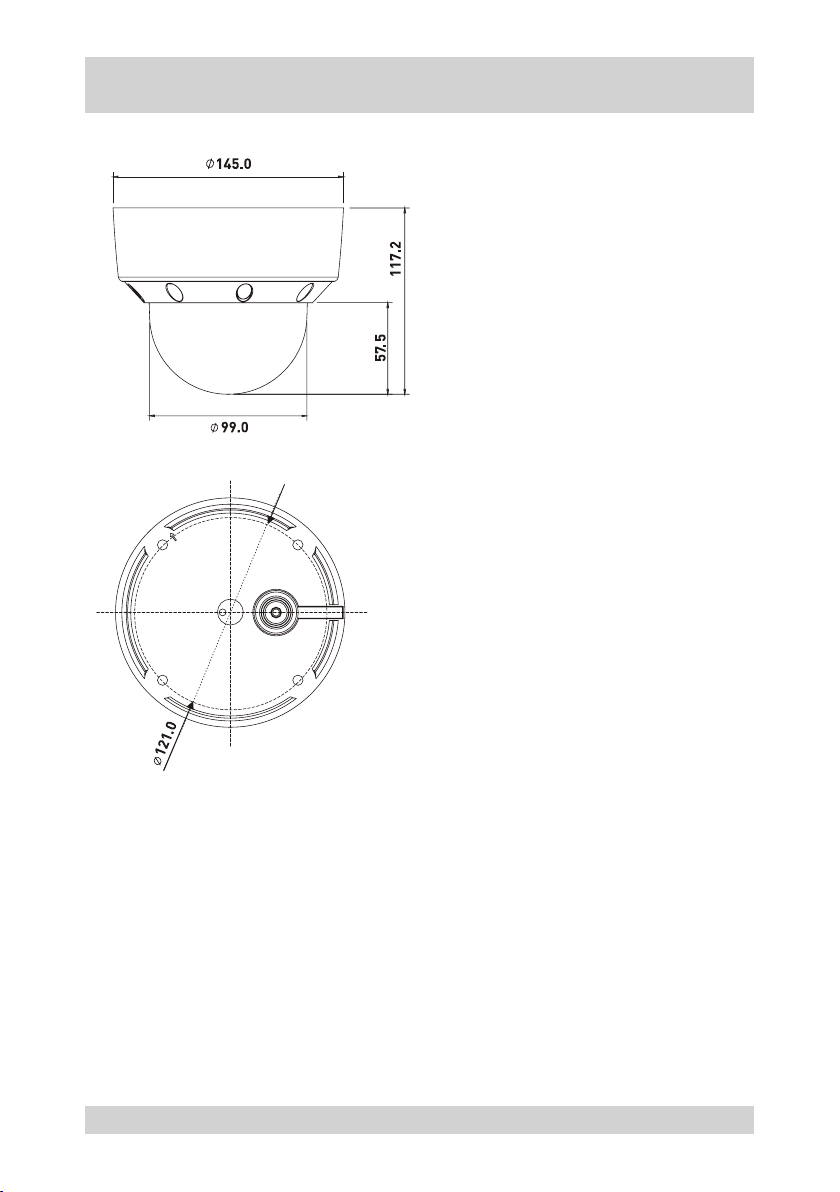
Dimensional Drawings
Dimensions in mm
NTD-4101
47
Page 48

Index
A
Accessories 46
AE control
28
Alarm
Input 17
Reset 22
Allocating the IP address 38
Ambient conditions 3
Audio
Input 17
Output 17
Automatic image reversal
Activate 36
Operating 22
B
Basic functions 7
C
Cable routing
In the pipe 16
Camera control
NT-Manager 40
Web browser 41
Camera menu
Menu descriptions 26
Camera menu tree 24
Checklist for getting started 10
Cleaning 3
Colour standard 18
Connecting the camera 13, 16, 17
Connections 8, 9
Connector imprint 15
Control cable 15
Control options 7
Control protocol 18
D
Delivery state
Reset camera part 31
Reset dome part 36
Dimensions 47
Display software version 36
Disposal 50
Dome cover
Closing and securing 14
Open 14
Drilling template 13
E
EMC class 3
Enhancing the temperature range
See heater kit 16
Exposure control 28
F
Features 7
G
Getting started
Camera 3
Checklist 10
Requirements 7
H
Heater kit 16
I
ID address
Calculating 19
Setting 18
Installation
Rubber ring gasket 15
Installing the camera 12
Ceiling or wall 15
48
NTD-4101
Page 49

Index, continued
J
Joystick 20
K
Keypad 20
M
MAC address 10, 38
Menu descriptions
Camera menu 26
N
Network connection setup 11
P
Package contents 7
R
Recycling the VCR 50
RS-485 17
S
Safety instructions 3
Safety rope
Installation on structure 15
Installation on the camera 12
Setting up network connectivity 38
Shutter speed 28
Specications 43
Structure 8, 9
T
Terminating 9
W
White balance 27
NTD-4101
49
Page 50

Notes on disposal
Proper disposal of this camera
WEEE (Waste Electrical & Electronic Equipment)
Applicable in the member states of the European Union and other European countries with a separate collection system.
The marking on the camera and on the related documentation stipulates that it must
not be thrown away in normal domestic waste at the end of its useful life.
General rules
Avoid uncontrolled waste disposal: Please dispose of this camera separately from other waste, to avoid
►
posing a hazard to the environment and to human health.
Recycle the camera in order to support the sustainable reuse of material resources.
►
Private users
Contact the retailer from whom you purchased the camera, or your competent local authority to nd out how
►
you can recycle the camera in an environmentally friendly way.
Commercial users
This camera must not be discarded with trade waste. To clarify the conditions of disposal, check your
►
purchase contract or contact your supplier.
50
NTD-4101
Page 51

Page 52
eneo® is a registered trademark of Videor E. Hartig GmbH
Exclusive distribution through specialised trade channels only.
Videor E. Hartig GmbH
Carl-Zeiss-Str. 8 · 63322 Rödermark, Germany
Tel. +49 (0) 6074 / 888-0 · Fax +49 (0) 6074 / 888-100
www.videor.com
Operating Instructions version 09/2008 (V1.0)
Subject to technical change without notice.
© Copyright by Videor 2008
 Loading...