

Eneo NTC-4151/PP Installation And Operating Manual
1
Installation and Operating Manual
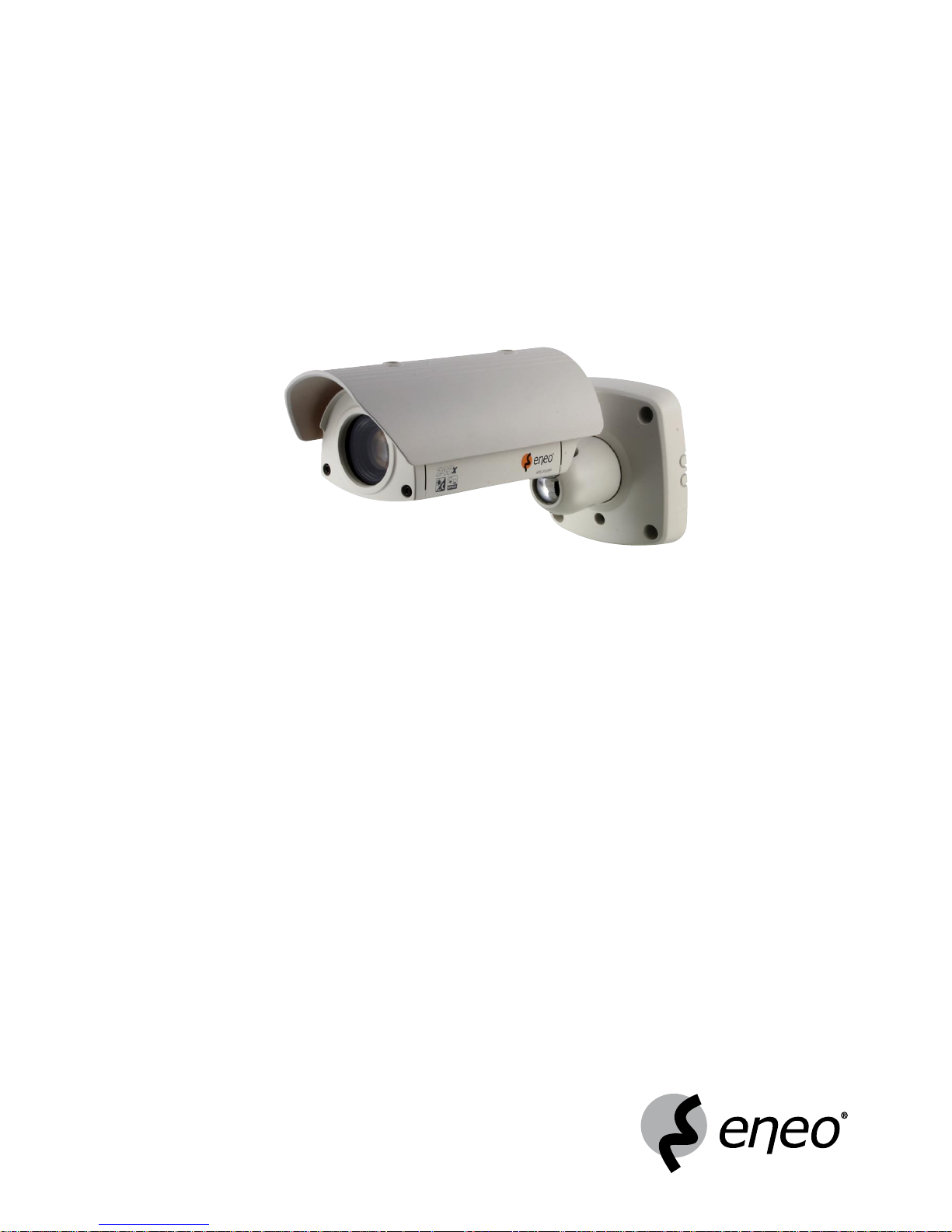
1/4” Network Day/Night Camera, Outdoor Housing, 22x Zoom
NTC-4151/PP

2
Contents
1. Safety Instructions ........................................................................................................................................................................................................................... 3
2. Introduction .....................................................................................................................................................................................................................................
3
2.1 General Description ................................................................................................................................................................................................................ 3
3. Network Camera Installation ............................................................................................................................................................................................................
4
3.1 Package Contents ................................................................................................................................................................................................................... 4
3.2 Operation Requirements ......................................................................................................................................................................................................... 4
3.3 Parts Name ............................................................................................................................................................................................................................. 5
3.4 Installation .............................................................................................................................................................................................................................. 5
3.4.1 Instillation 1 (Cable through the Wall with the Mount Base) ........................................................................................................................................ 6
3.4.2 Instillation 2 (Using the Conduit Knockout punched with Mount Base) ......................................................................................................................... 7
3.5 Connection .............................................................................................................................................................................................................................8
3.5.1 Colour Lead Wire & Colour Display Label .................................................................................................................................................................... 9
3.5.2 External Day/Night Control ......................................................................................................................................................................................... 9
3.5.3 RS-485 Connection .................................................................................................................................................................................................... 9
3.6 External A/D Key Control ....................................................................................................................................................................................................... 10
3.7 Setting up Network Connectivity ........................................................................................................................................................................................... 11
3.7.1 Allocating or Changing the Camera IP Address ........................................................................................................................................................ 11
3.8 Camera Control via NT Manager ........................................................................................................................................................................................... 12
3.8.1 NT Manager Main Menu ........................................................................................................................................................................................... 12
3.8.2 Logging on the Camera in the Network..................................................................................................................................................................... 13
4. Camera Adjustment
........................................................................................................................................................................................................................ 14
4.1 OSD Main Screen ................................................................................................................................................................................................................. 14
4.2 Main Menu ...........................................................................................................................................................................................................................14
4.2.1 WB (White Balance) .................................................................................................................................................................................................. 14
4.2.2 AE (Auto Exposure) ................................................................................................................................................................................................... 15
4.2.3 BLC (Back Light Compensation) ............................................................................................................................................................................... 15
4.2.4 TITLE ....................................................................................................................................................................................................................... 15
4.2.5 DISPLAY ................................................................................................................................................................................................................... 16
4.2.6 CAM SET .................................................................................................................................................................................................................. 16
4.2.7 EFFECT .................................................................................................................................................................................................................... 16
4.2.8 PRESET .................................................................................................................................................................................................................... 17
5. Camera Control via Web Browser ...................................................................................................................................................................................................
18
5.1 Connecting camera with Web Browser .................................................................................................................................................................................. 18
5.2 Real-Time Monitoring ........................................................................................................................................................................................................... 19
5.3 NETWORK CAMERA Setting................................................................................................................................................................................................... 20
5.3.1 Video Setting ............................................................................................................................................................................................................ 20
5.3.2 Alarm Setting ...........................................................................................................................................................................................................21
5.3.3 PTZ Setting .............................................................................................................................................................................................................. 24
5.3.4 System Setting ......................................................................................................................................................................................................... 26
5.4 Help...................................................................................................................................................................................................................................... 35
6. Troubleshooting ............................................................................................................................................................................................................................. 35
6.1 Preventive Maintenance........................................................................................................................................................................................................ 35
7. Specifications ................................................................................................................................................................................................................................ 36
8. Dimensional Drawings ...................................................................................................................................................................................................................
38
Betriebsanleitung
Installation and Operating Instructions
Mode d”emploi
Instrucciones de manejo
www.videor.com

3
1. Safety Instructions
• Read these safety instructions and the operation manual first before you install and commission the camera.
• Keep the manual in a safe place for later reference.
• Protect your camera from contamination with water and humidity to prevent it from permanent damage.
Never switch the camera on when it gets wet. Have it checked at an authorized service center in this case.
• Never operate the camera outside of the specifications as this may prevent the camera functioning.
• Do not operate the cameras beyond their specified temperature, humidity or power ratings.
Operate the camera only at a temperature range of -10°C to +50°C and at a humidity of max. 90%.
• To disconnect the power cord of the unit, pull it out by the plug. Never pull the cord itself.
• Pay attention when laying the connection cable and observe that the cable is not subject to heavy loads, kinks, or damage and no moisture can get in.
• Do not attempt to disassemble the camera board from the dome.
• The warranty becomes void if repairs are undertaken by unauthorized persons. Do not open the camera housing.
• Installation, maintenance and repair have to be carried out only by authorized service centers.
Before opening the cover disconnect the unit from mains input.
• The fitter is responsible for the system of protection being followed in accordance with the technical data, e.g. by sealing of the cable outlet with silicone.
• Contact your local dealer in case of malfunction.
• Only use original parts and original accessories from Videor E. Hartig GmbH.
• Do not use strong or abrasive detergents when cleaning the dome. Use a dry cloth to clean the dome surface.
In case the dirt is hard to remove, use a mild detergent and wipe gently.
• Do not open the camera housing in order to install the camera.
If you do open it, however, bear in mind that the front part of the housing is not secured by an arresting cable, i.e. that the heating supply is NOT fitted
with a cord grip and can be torn away by the weight of the front part.
NOTE: This is a class A digital device. This digital device can cause harmful interference in a residential area; in this case the user may be required to take
appropriate corrective action at his/her own expense.
2. Introduction
2.1 General Description
The Day & Night AutoFocus Zoom color DSP Network Camera provides especially for closed circuit television (CCTV) and security surveillance application.
The Network Camera supports the operation through the network.
• 1/3” Super HAD Farb/SW CCD Sensor
• Sensitivity of 0.2Lux at F1.2 (Colour)
• Digital Noise Reduction (DNR)
• High and Low Speed Shutter Control (MES/ESC/DSS)
• On-screen Menu Control
• Camera Title Display
• Privacy Masking
• Mirror Function
• Motion Detection
• MPEG-4 Compression
• Image Frame Rate: Up to 25 Fr./sec. (720x576 pixel)
• Viewer for Monitoring, Recording and Configuration
• Pre and Post Event Recording (in Client PC)
• Integrated Web Server: 10Base-T/100Base-TX
• All-In-One: Camera / Lens / Housing IP66
4
3. Network Camera Installation
Installation of the camera must be performed by qualified service personnel in accordance with all local national electrical and mechanical codes must perform instal
-
lation of the camera.
Perform the following steps to install the camera
3.1 Package Contents
• Camera
• Instruction Manual
• Connection Cable
• RJ-45 Coupler
• Install CD
• A/D Remote Controller (option)
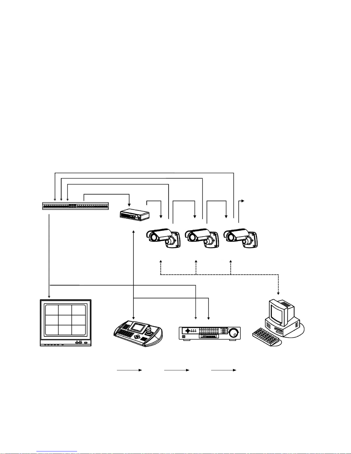
3.2 Operation Requirements
RS-485
Kamera 1
Multiplexer
Video
Monitor
Kamera 2 Kamera 3 ...
J-Box
RS-485
LAN
Fernsteuerung DVR / VCR PC-Programm
LAN RS-485 VIDEO
5
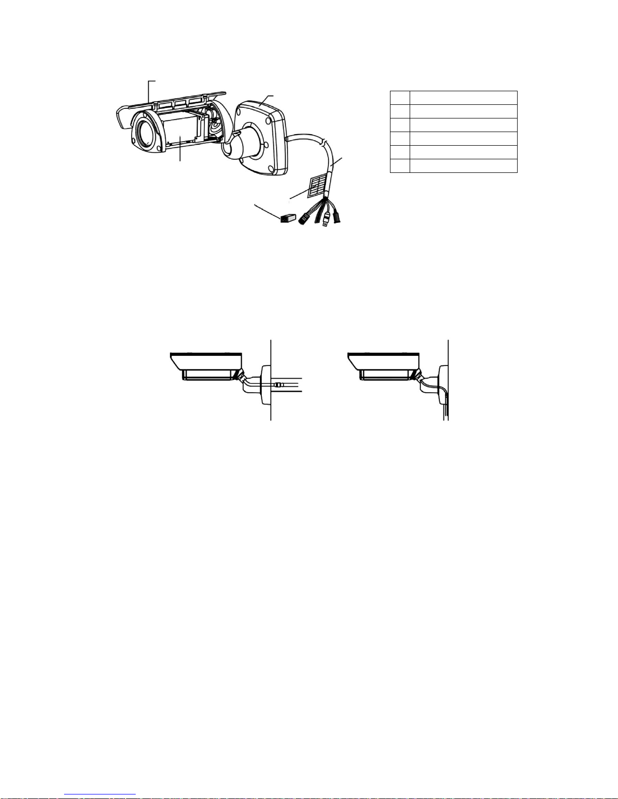
3.3 Parts Name
1
Sunshield
2
AF D&N camera module
3
Mount base
4
Connection cable
5
Cable label
6
RJ-45 coupler
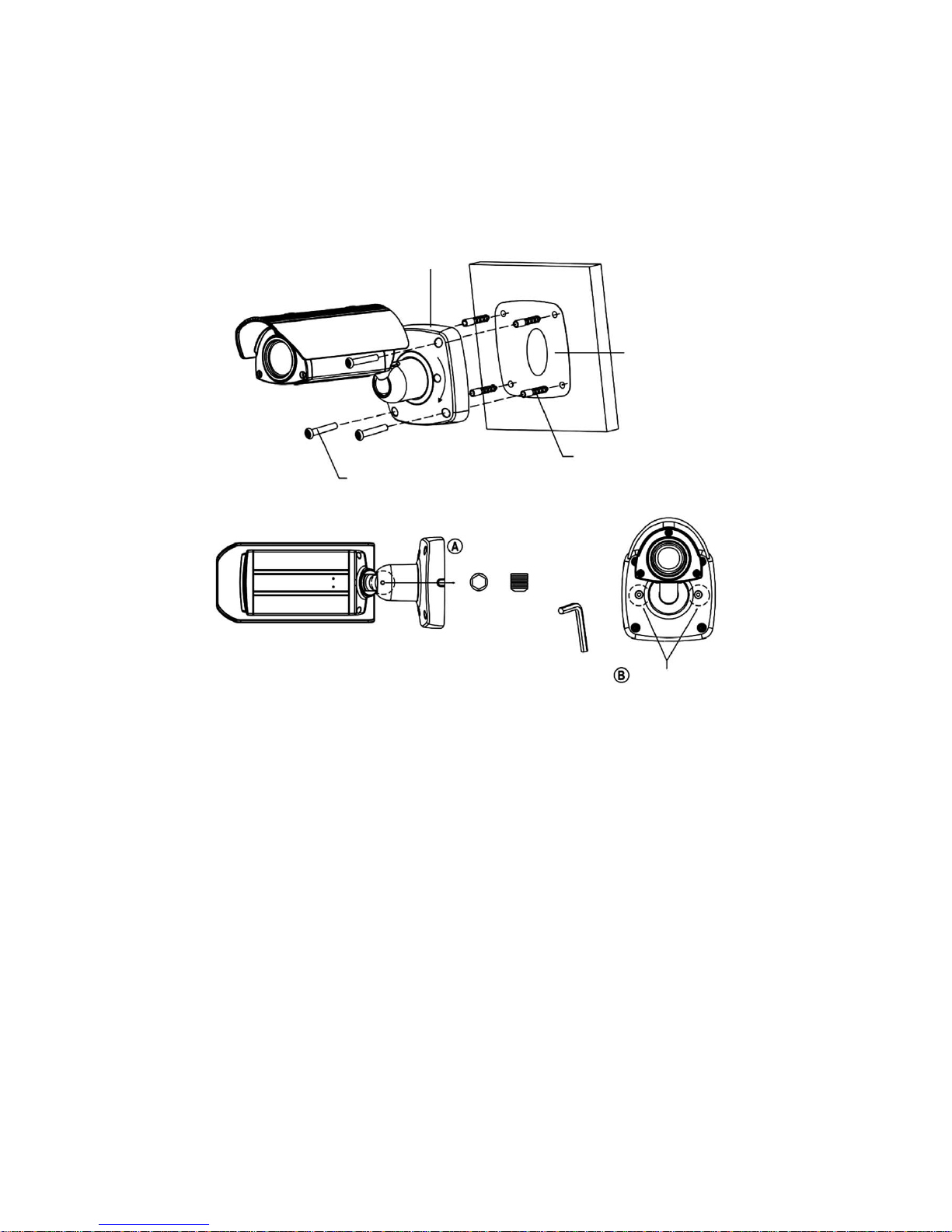
3.4 Installation
There are two ways of installing the camera.
1. Cable through the wall with mount base. 2. Using the conduit knockout punched with
the mount base.
1
3
4
5
6
2
6
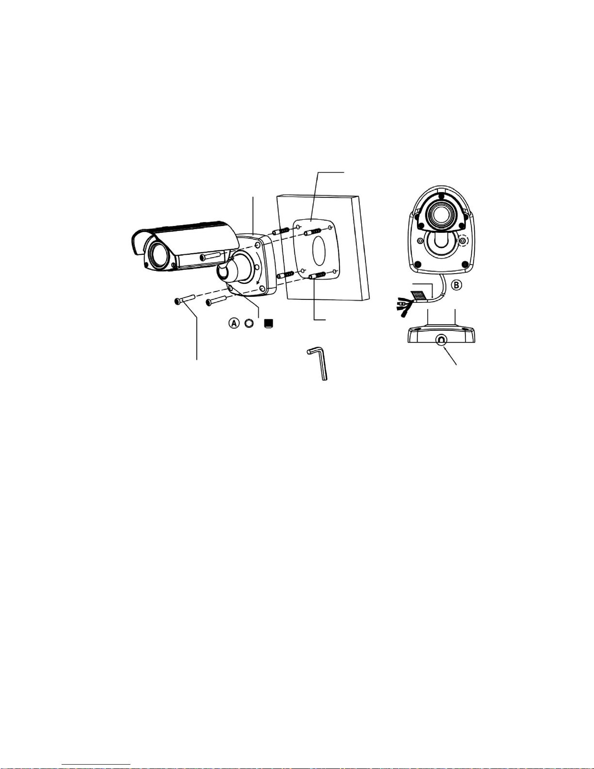
3.4.1 Installation 1 (Cable through the Wall with the Mount Base)
A. Drill the mounting location, using the template sheet (or the bottom of the mount base) as a template.
B. Insert the plastic anchors into the hole which has just drilled.
C. Connect BNC cable and communication lines.
D. Fit the screw holes of the mount base into the plastic anchors.
E. Screw up the mount screws (T-20).
F. Adjust the camera suitably using the pan & tilt function, and fasten both the socket set screw „A” (1x) and torx lock screw „B” (2x) to fix the camera.
Mount base
Wall
Template sheet
Plastic anchors (4x)
Torx screws (T-20)
M6.0 x 35.0 (4x)
Socket set screw
M5.0, L=5.0mm
Hexagon wrench
Torx lock screw (T-20)
7
3.4.2 Instillation 2 (Using the Conduit Knockout punched with Mount Base)
A. Drill the mounting location, using the template sheet (or the bottom of the mount base) as a template
B. Insert the plastic anchors into the hole which has just drilled.
C. Connect BNC cable and communication lines.
D. Fit the screw holes of the mount base into the plastic anchors.
E. Remove the conduit knockout punched for the cable entry.
F. Screw up the mount screws (T-20).
G. Adjust the camera suitably using the pan & tilt function, and fasten both the socket set screw „A” (1x) and torx lock screw „B” (2x) to fix the camera.
Mount base
Wall
Template sheet
Plastic anchors (4x)
Torx screws (T-20)
M6.0 x 35.0 (4x)
Socket set screw
M5.0, L=5.0mm
Hexagon wrench
A conduit knockout punched
for the cable entry
Cable
Torx lock screw (T-20)
8
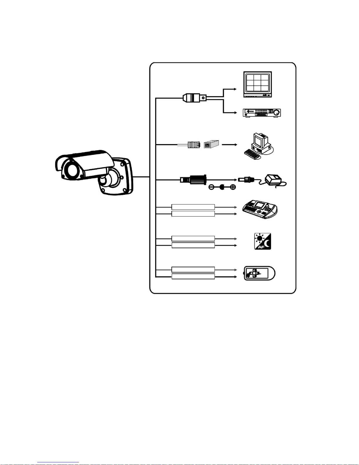
3.5 Connection
CAUTION: Do not connect the power cable until all other connections have been completed. if you complete the whole connection of cameras, then you
have to cut the extra cable.
Video (BNC)
Monitor
DVR / VCR
PC Program
Power connection
A/D key control
RS-485 connection
Day & night control
to local Internet networks
(blue)
(green)
(sky-blue)
(pink)
(black/white)
(orange)
9
3.5.1 Colour Lead Wire & Colour Display Label
Colour Description
Yellow jack Video OUT
Red jack DC IN
RJ-45 jack
LAN
Pink EXT-OUT
Sky-blue EXT-IN
Black GND
White GND
Blue RS-485 (–)
Green RS-485 (+)
Orange A/D KEY
Connection cable description
3.5.2 External Day/Night Control
GND (black)
EXT-OUT (pink)
EXT-IN (sky-blue)
External sensor switch ON/OFF
• DAY/NIGHT
Day: open
Night: closed
• EXT-OUT
NO
NC
Colour
B/W
B/W
Colour
Is connect to an external sensor to receive day/night detection signals.
NOTE: To validate the sensor inputs, select Function menu B/W mode the EXT.
3.5.3 RS-485 Connection
The Camera can be controlled remotely by an external device or control system, such as a control keyboard, using RS-485 half-duplex. Connect Market Rx+, Rx- to Tx+
and Tx- of the RS-485 control system.
RS-485
RS-485 (+)
(black)
RS-485 (–)
(pink)
10
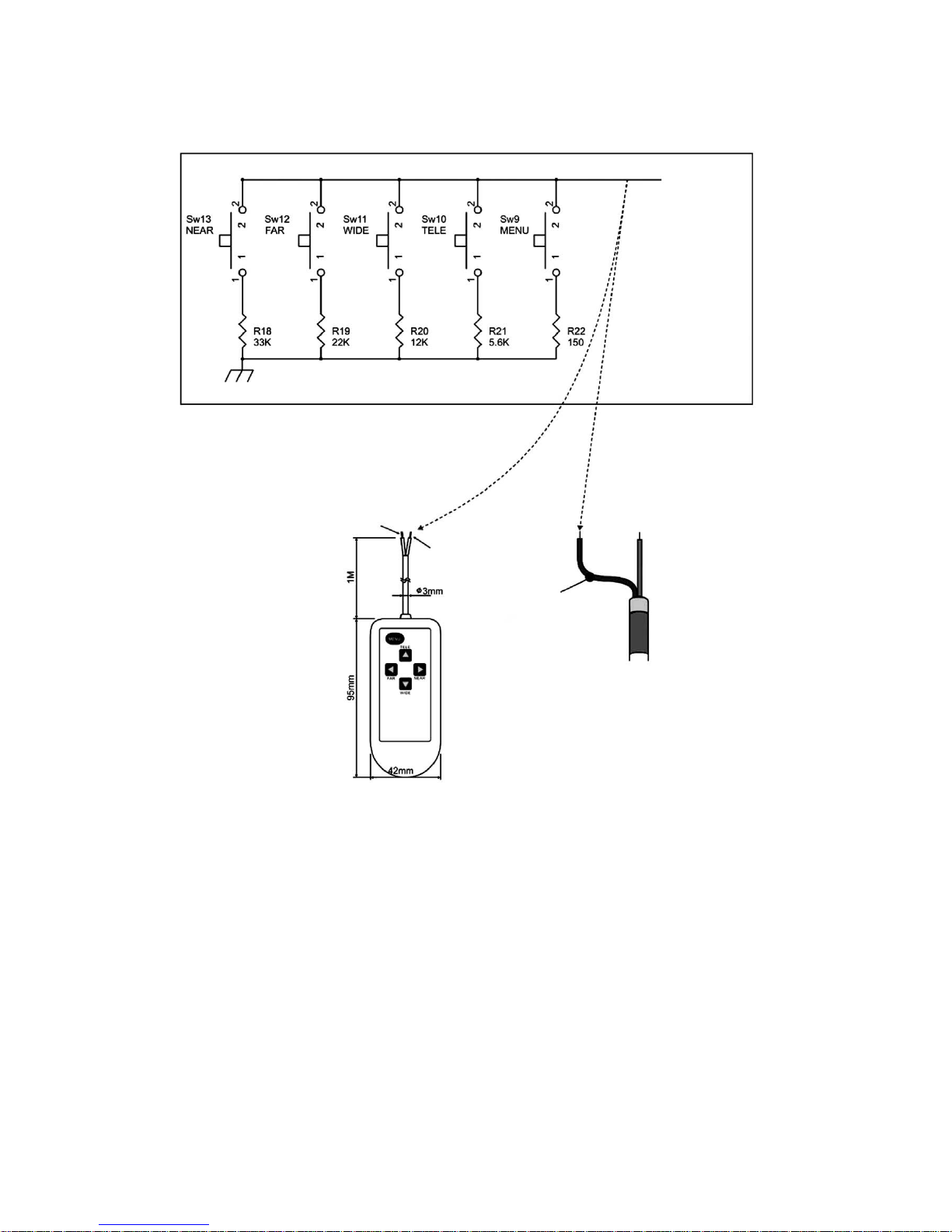
A/D KEY (white)
A/D KEY2
(orange)
A/D KEY
AD KEY2
Remote controller
3.6 External A/D Key Control
External Controller Circuit Schematic
GND (black)
Remote controller (#92192)
11
3.7 Setting up Network Connectivity
3.7.1 Allocating or changing the camera IP address
Requirements:
• PC with fixed IP address available.
• In WINDOWS XP, the firewall is disabled during IP allocation.
• CD with viewer software (NT Manager), setup software and client software available.
• Camera and PC are connected via a standard RJ-45 crossover cable in a network-compatible way.
• MAC address of the camera is known.
• Free IP address for camera is known.
• Name of the employed Ethernet adapter is known.
Step Action Menu path/menu item
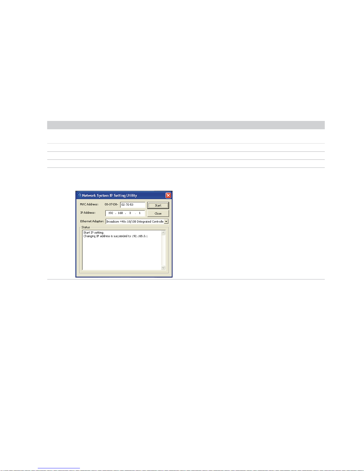
1 Execute and/or save setup software and client software from the CD.
Result: The „Network System IP Setting Utility“ window is opened.
IP setting utility
2 Complete the MAC address of the camera. MAC address
3 Enter the IP address of the camera. IP address
4 Select the Ethernet adapter of the PC. Ethernet adapter
5 Log on the camera in the network.
Result: The IP address is allocated to the camera.
START
12
3.8 Camera Control via NT Manager
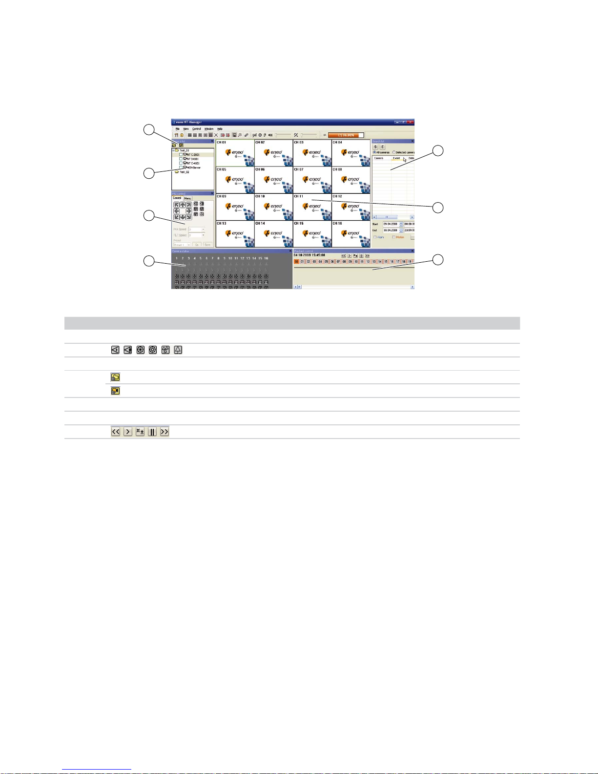
3.8.1 NT Manager Main Menu
The following figure and the table describe the main menu of the NT manager:
No. Designation Function
1
Display
Camera status
2
PTZ control
3 Display Camera list
4
Add group
Add camera
5 Display Search list
6 Display Monitoring image
7 Playback control
3
4
2
1
6
7
5
Additional information
The complete software description of the NT Manager can be found in the Help function of the NT Manager software.
 Loading...