

Eneo DTR-6108/xxxD, DTR-6116/xxxD, DTR-6108/250D, DTR-6116/250D Operating Instructions Manual
Operating Instructions
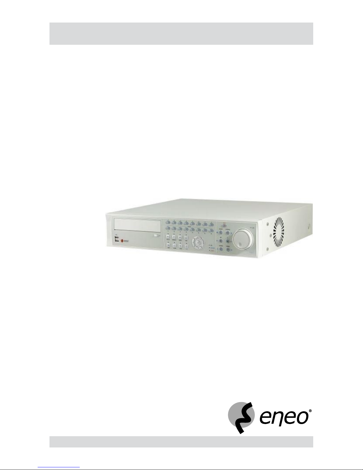
Digital Video Recorder
Models: DTR-6108/xxxD
DTR-6116/xxxD


3
DTR-61XX
Safety instructions
EMC class
This video recorder (DVR) is a class A device in accordance with EN 55022.
This device may cause interference to other equipment in domestic use. In such cases the persons operating the DVR are required to provide appropriate countermeasures, for which they themselves bear the cost.
►
►
Importance of these Operating Instructions
Please read the safety instructions and the other information contained in the Operating Instructions before
connecting up and operating the DVR.
The Operating Instructions should be kept in a safe place for later reference.
►
►
Ambient conditions for the DVR
The DVR should be protected against excessive heat, dust, damp and vibration.
The DVR may only be operated at temperatures between +5°C and +40°C, and up to a maximum air
humidity of 90%.
The DVR may only be operated indoors, and must be protected against incursion of water and damp.
►
►
►
Care of the DVR
Never switch on the DVR when damp has penetrated it. In such cases, have the DVR checked by a qualied
service engineer.
Do not place any heavy objects on the DVR.
Never cover over the DVR's vents.
Never insert metal objects or any other items into the vents. This may permanently damage the DVR.
The housing may only be opened by authorised persons. Repairs may only be carried out by qualied
service personnel.
The DVR must be disconnected from the power supply before its housing is opened.
►
►
►
►
►
►
Getting started with the DVR
When laying the connecting cables, make sure no weight is placed on them, that they are not kinked or
damaged, and that no damp can penetrate them.
►
Cleaning the DVR
The housing of the DVR may only be cleaned with a damp (not wet) cloth,
Use only a mild detergent. Do not use solvent-containing detergents or petrol. This could permanently
damage the surface nish.
►
►
Spare parts
Use only original spare parts from Videor E. Hartig GmbH.►


5
DTR-61XX
Table of contents
Overview 7
Package contents
7
Basic functions
7
Features
7
Requirements for operation
7
Control options
7
Connections on the rear
8
Front panel controls
9
Key to controls 1
0
Function buttons 1
0
PTZ camera functions 1
0
Playback functions 1
0
Remote control functions 1
1
Playback functions 1
1
Menu overview 1
2
Accessing the menus 1
4
Accessing the Display menu 1
4
Accessing the PTZ menu 1
4
Accessing the Setup menu 1
5
Accessing the Search menu 1
5
Getting started
16
Checklist for DVR operation 1
6
Connecting the remote control and DVR 1
6
Switching on the DVR 1
7
Switching off the DVR 1
7
Administration 1
8
Saving your system setup 1
8
Loading your system setup 1
8
Deleting recordings 1
9
Downloading software updates 19
Hiding from specic users 1
9
Restoring factory defaults 2
0
Mirroring of hard disks 2
1
Determining the memory requirement of a recording 2
2
Searching for recordings 2
3
Using calendar search 2
5
Using record table search 2
6
Using event log search 2
7
Using text-in search 2
8
Using motion search 3
0
Copying recordings 3
1

6
DTR-61XX
Table of contents
Menu descriptions – Setup menu 32
System – Information 3
3
System – Date/Time 3
4
System – Storage 3
5
System – User 3
7
System – Shutdown 3
8
System – Log out user1... 3
8
Network – Network 3
8
Network – Notication 4
1
Devices – Camera 4
2
Devices – Audio 4
3
Devices – Alarm-Out 4
4
Devices – Display 4
5
Devices – Remote Control 4
7
Record – Record 4
8
Record – Schedule 4
9
Record – Pre-Event 5
0
Record – Archive 5
1
Event – Alarm-In 5
2
Event – Motion Detection 5
4
Event – Video Loss 5
6
Event – Text-In 5
8
Event – System Event 6
1
Event – Event Status 6
3
WebGuard – WebWatch controls 6
4
WebGuard – WebSearch controls 6
5
Using WebGuard 6
6
Specications DTR-6108 6
7
Specications DTR-6116 6
9
Accessories 7
1
Supported PTZ cameras 7
2
Index 7
3
Notes on disposal 7
6

7
DTR-61XX
Overview
Package contents
Digital video recorder (DVR)
Mains power cord
Operating instructions
RAS (Remote Administration System) software on CD
Operating instructions for RAS software on paper and CD
Mounting kit for cabinet installation
Screws for attaching SCSI Connector
Mounting screws and guides for installation of hard disk drives
Infrared remote control
Basic functions
Record video images using multiple cameras
Event-based recording start
Video playback
Search for specic video sequences
Features
MPEG-4 compression / triplex mode
8 or 16 loop-through inputs / VGA, S-VHS/FBAS outputs
Audio and alarm inputs / outputs
Max. recording speed DTR-6108/xxxD: 200 eld images per sec (PAL) / D1: 50 eld images per sec (PAL)
Max. recording speed DTR-6116/xxxD: 400 eld images per sec (PAL) / D1: 100 eld images per sec (PAL)
Memory capacity 250 GB / 500 GB / 750 GB / 1000 GB / 1750 GB
Maximum video resolution 720 x 576 pixels
SCSI port for archiving / memory expansion
Various recording criteria possible
Archiving/image transfer via USB and DVD-RW
ATM/POS text display / 2x to 4x digital zoom
Telemetry control functions via RS-485 port
Network port (Ethernet) / IR remote control
Requirements for operation
Digital video recorder DTR connected
At least 1 camera (PAL) and 1 monitor connected.
Mouse connected, if DVR is to be controlled by mouse
Note: Please refer to www.videor.com for further information.
Control options
Front panel
Remote Control
Mouse
WebGuard
RAS program
●
●
●
●
●
●
●
●
●
●
●
●
●
●
●
●
●
●
●
●
●
●
●
●
●
●
●
●
●
●
●
●
●
●
8
DTR-61XX
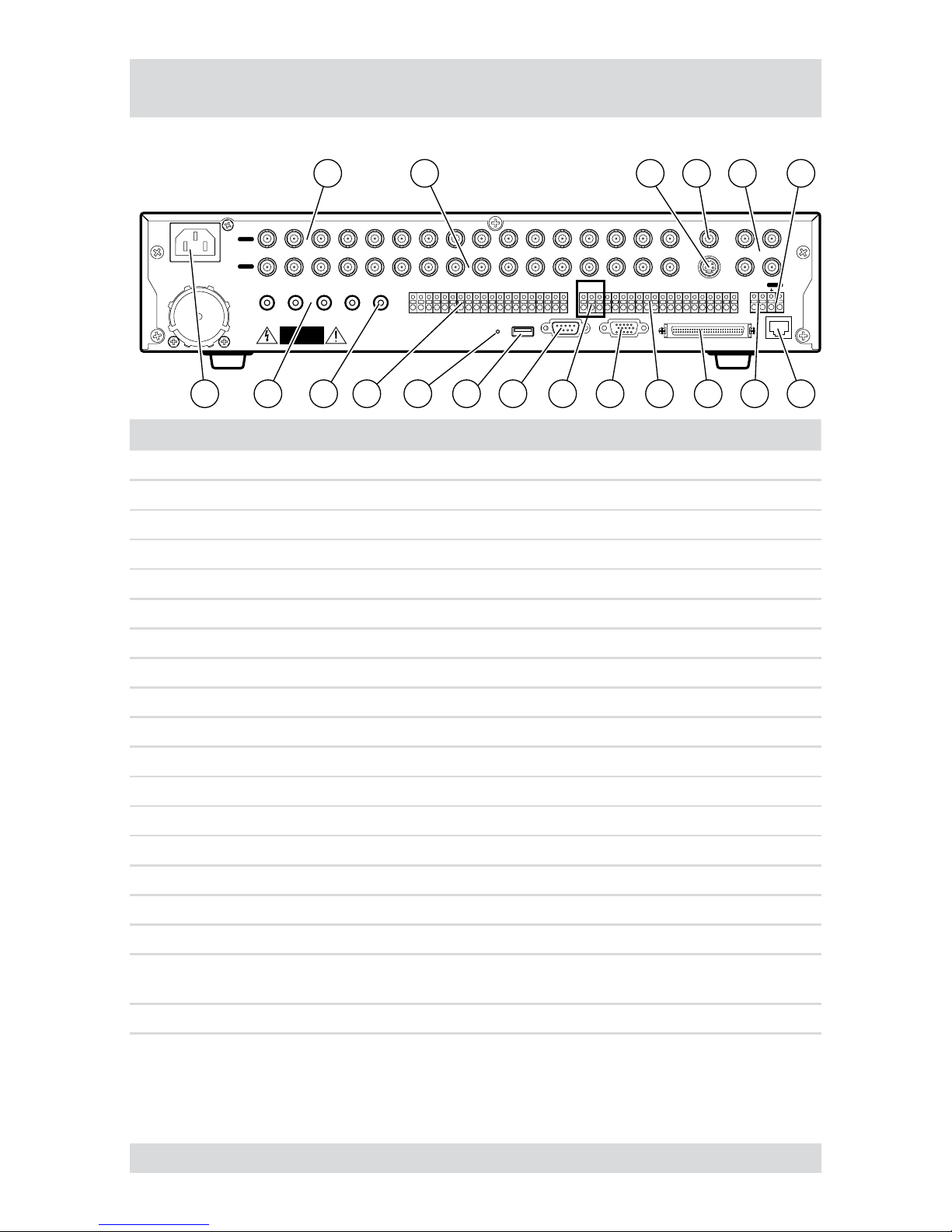
Connections on the rear
Note: Connections optionally for NTSC or PAL operation.
AUDIO IN 1 AUDIO IN 2 AUDIO IN 3 AUDIO IN 4 AUDIO OIT
VIDEO IN
LOOP
1122334
4
5
5
6
6
7
7
889910101111121213131414151516
16
SPOT 1 SPOT 2
SPOT 3 SPOT 4
VIDEO OUT
SVHS OUT
NETWORKUSB RS-232C VGA SCSI
RS-485
ARI GNDNC COM NO AO2 AO4AO5 AO6 AO7
AO8 AO12 GND
GND
AO10AO9 AO11 AO13 AO14 AO15 AO16
AO3
AI1 AI2 AI3 AI4 AI5 AI6 AI7 AI8
GND GND GND
AI9
AI11AI10 AI12 AI13 AI14 AI15 AI16
GND
CAUTION
RISK OF ELECTRIC SHOCK
DO NOT OPEN
1 2 3 4 5 6
14 13 11121819 17 1516 910 8 7
No. Designation Functions/connections Example devices
1 VIDEO IN 1-16 Max. 16 video channels Cameras
2 LOOP 1-16 Max. 16 loop-through video channels Cameras
3 SVHS OUT S-VHS output Monitors
4 VIDEO OUT Video output Monitors
5 SPOT1 - SPOT4 Max. 4 video outputs Spot monitors
6 RS-485 External interface Keyboard, PTZ camera
7 NETWORK Network Network cable
8 ARI/GND Reset alarm with external signal Switch
9 SCSI External storage media Hard disk
10 AO2 - AO16 Alarm outputs for external devices Siren, ashing light
11 VGA PC monitor PC monitor
12 NC, COM, NO Relay alarm output for external device Siren, ashing light
13 RS-232C
External interface Remote Control
14 USB External interface Drive, mouse
15 Reset switch Reset to factory defaults -
16 AI1 - AI16 Alarm inputs for external devices Sensors
17 AUDIO OUT Audio output Amplier, speakers
18
AUDIO IN 1
- AUDIO IN 4
Max. 4 Audio inputs Microphone
19 Power supply Mains power connection -
9
DTR-61XX
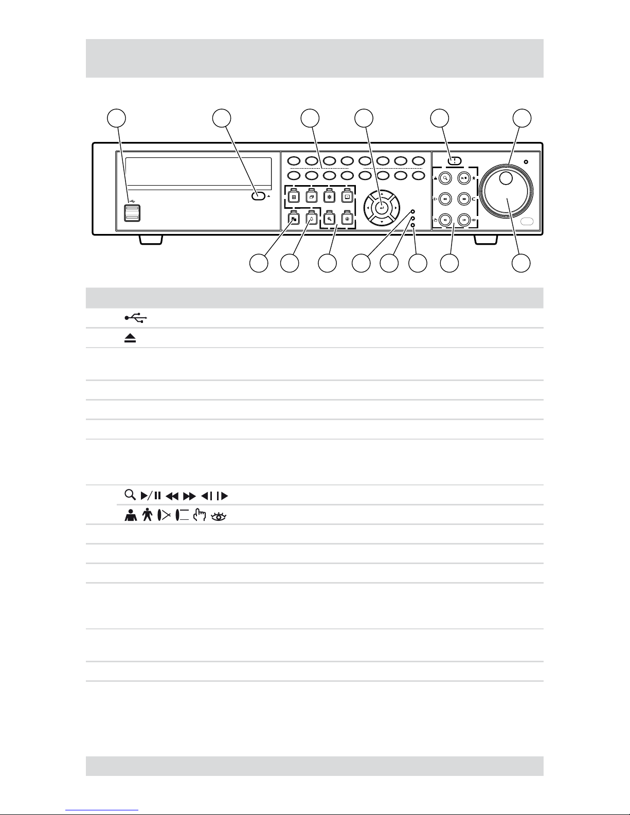
Front panel controls
The following diagram and table set out the controls on the front panel of the DVR:
CAMERA
PLAY
/PAUS
E
SEARCH
FFRW
FO
RWARD
BACKW
ARD
PANIC
HDD
NETWORK
POWER
JOG
DISPLAY
MENU
SEQUENCE
ALARM
SPOT
ZOOM
FREEZE
PTZ
192103114125136147158
16
1 32 4 5 6
14 13 1011 9 712 8
No. Designation Function
1 USB ports
2 Open built-in DVD-RW writer
3 1 to 16
Select cameras
Enter passwords
●
●
4 Menu navigation
Navigation and selection within the menu
5 PANIC
Start/end panic recording
6 Shuttle ring
Innitely adjust playback speed
7 Jog dial
Change size of frame in picture-in-picture mode
Change numerical values in Setup menu
Frame-by-frame playback in Play mode
●
●
●
8
Playback functions (primary assignment)
PTZ camera functions (secondary assignment)
9 POWER Power-on indicator when DVR is in operation
10 NETWORK Indicates Ethernet connection
11 HDD Indicates hard disk operation
12
DISPLAY, SEQUENCE,
FREEZE, SPOT, ZOOM,
PTZ
Function buttons
13
ALARM
Reset alarm
View event list
●
●
14 MENU Open/quit menu structure
10
DTR-61XX
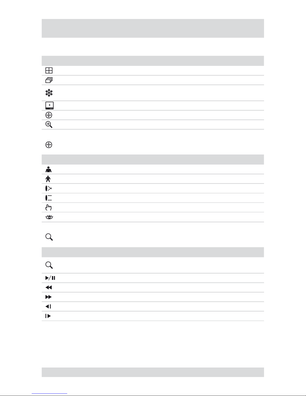
Key to controls
Function buttons
Element Function
Change display mode
Sequence On/Off
Freeze On/Off
Copying recordings in Search menu by pressing and holding down button
●
●
Spot monitor assignments
PTZ camera functions On/Off
Zoom On/Off
PTZ camera functions
Element Function
Zoom in
Zoom out
Close-up
Wide-angle
Save preset
Load preset
Playback functions
Element Function
Select Search/Play function
Stop playback
●
●
Start/pause playback
Fast rewind
Fast forward
Frame-by-frame rewind
Frame-by-frame forward
11
DTR-61XX
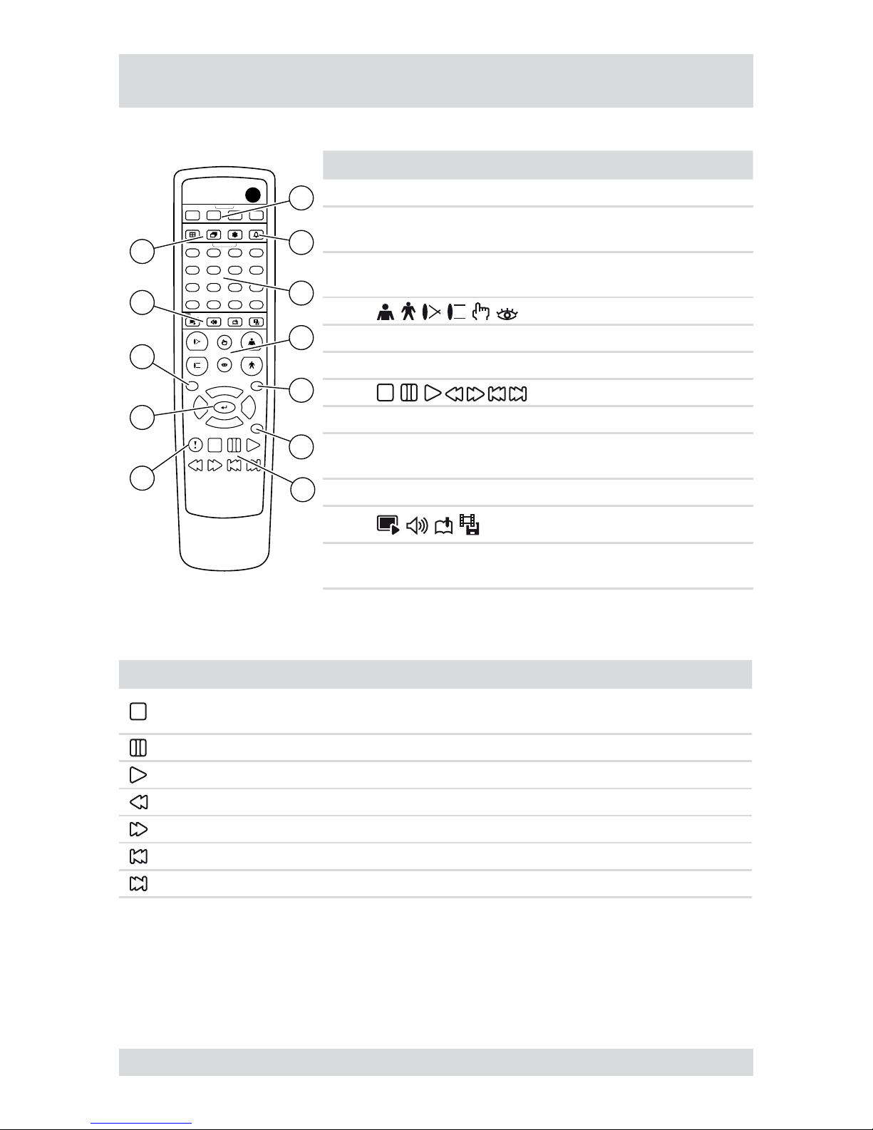
Remote control functions
The following diagram and table set out the functions on the remote control:
ID
Select System ID
DISPLAY
TRIPLEX
FOCUS PRESET
SET
VIEW
ZOOM
AUDIO
CLIP COPY
BOOK MARK
FREEZE ALARM
SEQUENCE
SPOT
CAMERA
2 3 41
1
5
9
13
2
6
10
14
3
7
11
15
4
8
12
16
MENU PTZ
ZOOM
PANIC
DIGITAL VIDEO RECORDER
Remote Controller
1
2
3
4
5
6
7
12
10
11
8
9
No. Designation Function
1
SPOT 1 - 4
Spot monitor assignments
2 ALARM
Reset alarm
View event list
●
●
3 1 to 16
Select cameras
Enter passwords
●
●
4
PTZ camera functions
5 PTZ PTZ camera functions On/Off
6 ZOOM Zoom On/Off
7
Playback functions
8 PANIC Start/end panic recording
9 Menu navigation
Navigation and selection within
the menu
10 MENU Open/quit menu structure
11
No function
12
DISPLAY, SEQUENCE,
FREEZE
Function buttons
Playback functions
Element Function
Select Search/Play function
Stop playback
●
●
Pause playback
Start playback
Fast rewind
Fast forward
Frame-by-frame rewind
Frame-by-frame forward
12
DTR-61XX
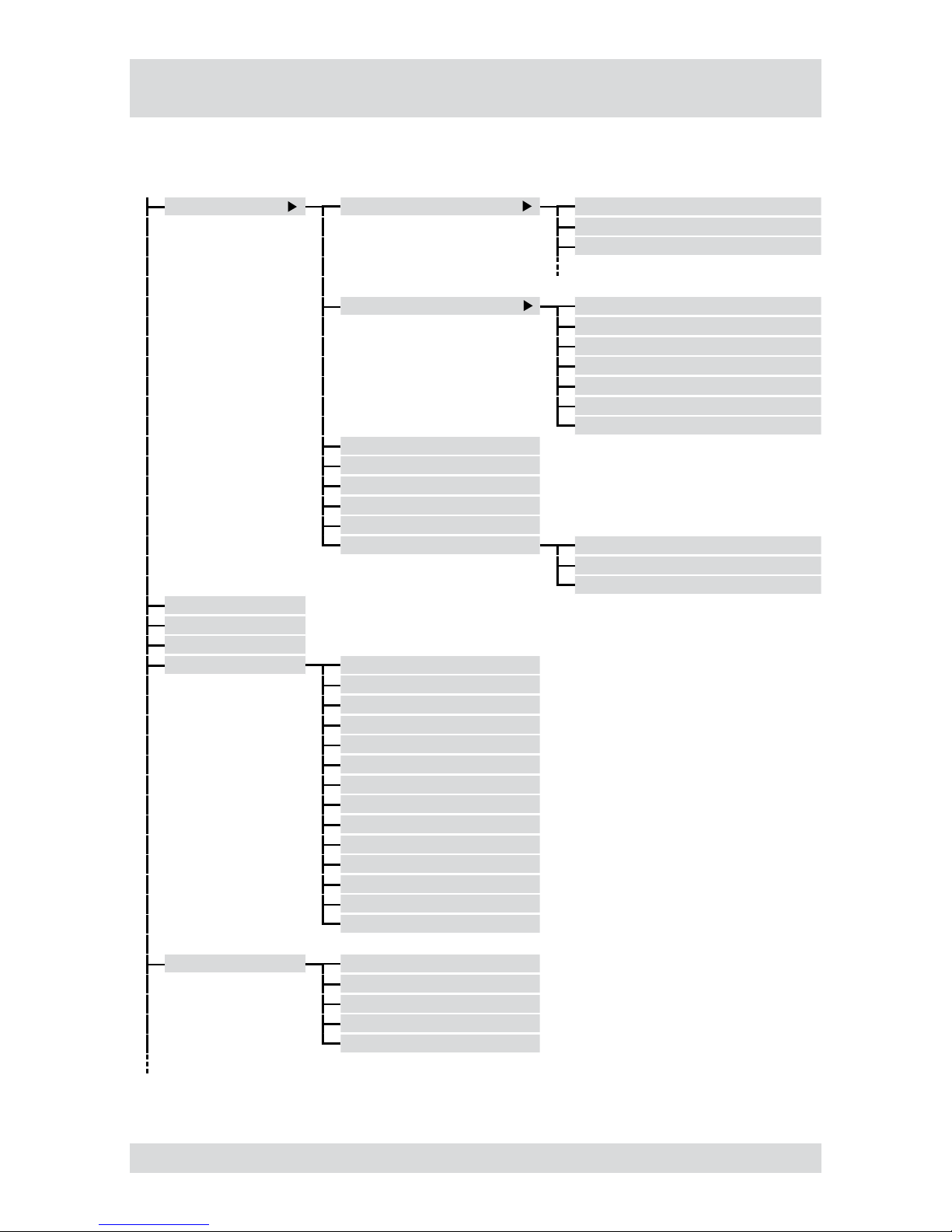
The following illustration shows the structure of the complete menu tree that is accessible using the mouse
control:
Display Camera 1. CAM1
2. CAM2
3. CAM3
PIP Left-Top
Left-Bottom
Right-Top
Right-Bottom
Size 1/16
Size 1/9
Size 1/4
2x2
3x3
4x4
Previous Group
Next Group
Edit Group Camera
Spot Monitor...
Exit Group Edit
Sequence
Freeze
Zoom...
PTZ... Speed
Auto Pan
Tour
Pattern
Device Menu
Light
Pump
Wiper
Power
Aux.
Move to Origin
Spot Monitor...
Toggle VGA...
Exit PTZ
Spot Monitor... Select Spot Monitor
Spot Monitor 1
Spot Monitor 2
Spot Monitor 3
Spot Monitor 4
Menu overview
13
DTR-61XX
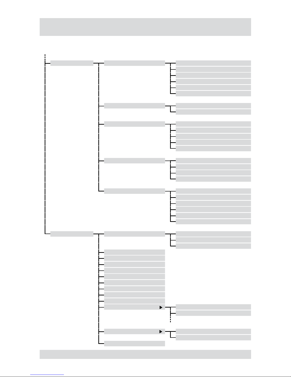
The following illustration shows the structure of the complete menu tree that is accessible using the mouse
control:
Setup Menu... System Information
Date/Time
Storage
User
Shutdown...
Log out user1...
Network Network
Notication
Devices Camera
Audio
Alarm-Out
Display
Remote Control
Record Record
Schedule
Pre-Event
Archive
Event Alarm-In
Motion Detection
Video Loss
Text-In
System Event
Event Status
Search Go to... First
Last
Date/Time
Calendar Search...
Record Table Search...
Event Log Search...
Text-In Search…
Motion Search...
Clip-Copy...
Print...
Zoom...
De-Interlace
Slow Play x1
x1/2
Data Source Record
Archive
Exit Search
Menu overview (continued)
14
DTR-61XX
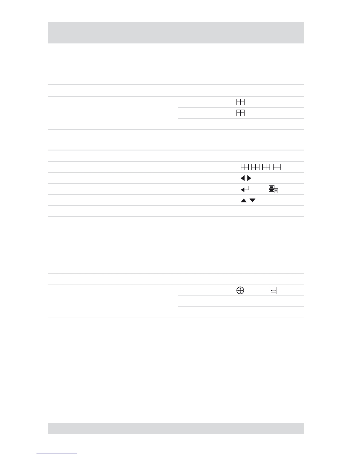
Accessing the Display menu
Requirement:
The current camera image is shown in full image or quad image.
Step Action Access using Key sequence/menu path
1 Open Display menu...
Device
Remote Control
Mouse Display
Access to submenu via Device/Remote Control
Submenu Camera image Key sequence
Change Display modes (PIP, 2x2, 3x3, 4x4)
Without frame
....
Previous/Next Group Without frame
Edit Group With frames >
Change position of image-in-image Without frame
Change size of image-in-image Without frame Jog dial
Accessing the PTZ menu
Requirement:
A PTZ camera is connected and congured.
Current camera image is shown as a full image.
Step Action Access using Key sequence/menu path
1
Open PTZ menu...
Result: Menu of the congured PTZ
camera is shown.
Device >
Remote Control PTZ > MENU
Mouse PTZ...
●
●
●
Accessing the menus
15
DTR-61XX
Accessing the Setup menu
Requirement:
The current camera image is shown in full image or quad image.
Step Action Access using Key sequence/menu path
1
Open Setup Menu...
Result: Prompt for user name and
password.
Device
Remote Control MENU
Mouse Setup Menu...
2
Log in as user.
User name: admin
Password: (blank)
Note: Use default access data only for
rst-time access.
Accessing the Search menu
Requirement:
The current camera image is shown in full image or quad image.
Step Action Access using Key sequence/menu path
1
Open Search menu...
Result: Search for recorded images is
activated.
Device >
Remote Control
> MENU
Mouse Search
●
●
Accessing the menus, continued

16
DTR-61XX
Getting started
Checklist for DVR operation
Step Action Menu path
1 Connect peripheral devices as per planned setup.
2 Specify menu language. Setup Menu... > System > Information
3 Adjust date and time. Setup Menu... > System > Date/Time
4 Set up user. Setup Menu... > System > User
5
Set up network and desired notication channels
(optional).
Setup Menu... > Network > ...
6 Register peripherals with DVR. Setup Menu... > Devices > ...
7 Set up event types and associated responses. Setup Menu... > Event > ...
8 Set up recording parameters and schedule. Setup Menu... > Record > ...
Connecting the remote control and DVR
The remote control and DVR can be assigned an ID, because the ID of each DVR in the network must be
unique. The DVR will then only respond to the remote control with the matching ID.
If the system ID in the DVR is 0, it will respond to the remote control regardless of the remote’s ID.
If the system ID in the DVR is not 0, you must set the ID of the remote control identically.
Step Action Menu path
1 Set DVR system ID. Setup Menu... > System > Information
2
Match remote control to system ID by
pressing ID button on remote control.
3 Select relevant number on remote control.
●
●

17
DTR-61XX
Getting started (continued)
Switching on the DVR
Requirement:
At least 1 camera (PAL) connected.
The start-up preparations are complete.
Step Action
1
Plug in DVR mains plug.
Result: The video recorder starts up automatically, checking the connected video inputs.
2
Switch on monitor.
Result: System is ready to use.
Switching off the DVR
Requirement:
You have accessed the Setup menu.
Step Action Menu path
1
Shut down the system.
Result: System shuts down automatically.
Setup Menu... > System > Shutdown...
2 After shutdown, disconnect the mains plug.
●
●
●

18
DTR-61XX
Administration
Saving your system setup
You can save your DVR’s setup data, including its network conguration.
Requirement:
USB memory stick
Software versions must be compatible
Step Action Menu path
1
Insert a USB memory stick into one of the USB
ports.
2 Export your setup.
Setup Menu... > System > Information >
Setup > Export...
3 Specify a le name.
4 Export your setup. Export
Loading your system setup
You can load your stored DVR system setup with or without its network conguration.
Requirement:
USB memory stick with stored setup
Software versions must be compatible
Step Action Menu path
1
Insert a USB memory stick into one of the USB
ports.
2 Import your setup.
Setup Menu... > System > Information >
Setup > Import...
3
Select the le name and, where appropriate, the
network conguration.
4 Import your setup. Import
●
●
●
●

19
DTR-61XX
Administration (continued)
Deleting recordings
You can only delete all your recordings together. It is not possible to delete recordings from a specic time
period.
Step Action Menu path
1 Delete all recordings.
Setup Menu... > System > Information > Clear All
Data...
or
Setup Menu... > System > Storage > Information >
Information > In Use > Clear
Downloading software updates
You can download software updates for your DVR from a USB memory stick.
Requirement:
USB memory stick with latest software release
Step Action Menu path
1
Insert a USB memory stick into one of the
USB ports.
2 Start update. Setup Menu... > System > Information > Upgrade...
3
Install new release.
Hiding from specic users
You can hide video images and camera data according to the preset user rights.
Step Action Menu path
1 Set camera Covert mode. Setup Menu... > Devices > Camera > Settings
2
Cancel ‘Covert Camera View' access for
specic users (groups).
Setup Menu... > System > User
●

20
DTR-61XX
Administration (continued)
Restoring factory defaults
Before restoring the factory defaults, you should export your current system settings in case you need to reimport them later. (see Saving your system setup and Loading your system setup)
Step Action
1 Shut down the system.
2 Disconnect the mains plug.
3
Push a paper clip into the Reset button (on the rear of the DVR) and hold it there.
4
Plug in the mains plug.
5
Wait for all the LEDs to ash 5 times (about 30 seconds).
6 Withdraw the paper clip.

21
DTR-61XX
Administration (continued)
Mirroring of hard disks
Mirroring of hard disks prevents the loss of records in the event of a hard disk defect.
Requirements:
The Digital Video Recorder has at least 2 or 3 hard disks installed
The destination hard disk is identical to the source hard disk in type and memory capacity
The source-hard disk and the destination hard disk are not used for archiving records.
Step Action Menu path
1 Formatting the source hard disk for recording.
Setup Menu... > System > Storage >
Information > Format > Record
2 Select the source hard disk.
Setup Menu... > System > Storage >
Information > Mirror 1/2 > Source
3 Select the destination hard disk.
Setup Menu... > System > Storage >
Information > Mirror 1/2 > Dest.
4
Start Mirroring.
Results:
Start...
The source hard disk and destination hard disk are
synchronised (approx. 40 minutes for 10 GB).
●
Note: The (re)synchronization will pause while
searching video.
All data on the destination hard disk are deleted.●
All records are written to both hard disks.●
5
Interrupting Mirroring.
Results:
Stop...
The status of the destination hard is set to:● Don't use
The hard disk can now only be used for searching
for records.
●
If the hard disk is to be used for records or archiving,
it must be formatted.
● Setup Menu... > System > Storage >
Information > Format > Format
6 Continuing Mirroring - see Starting Mirroring. Start...
●
●
●

22
DTR-61XX
Determining the memory requirement of a recording
The amount of memory recorded video sequences will take up depends on the following factors:
Picture quality
number of images per second
duration
The memory requirement is calculated by this formula:
Memory requirement = picture size x duration of recording x images per second
Calculation example: CIF resolution (PAL):
Picture
quality
Picture
size
Duration of
recording
Approx. memory space
5 images/s 10 images/s 25 images/s
Basic 2.4 kB 24 hours 1.04 GB 2.07 GB 5.18 GB
Standard 4.8 kB 24 hours 2.07 GB 4.15 GB 10.37 GB
High 9.6 kB 24 hours 4.15 GB 8.29 GB 20.74 GB
Very High 14.4 kB 24 hours 6.22 GB 12.44 GB 31.10 GB
Calculation example: 2CIF resolution (PAL):
Picture
quality
Picture
size
Duration of
recording
Approx. memory space
5 images/s 10 images/s 25 images/s
Basic 4.8 kB 24 hours 2.07 GB 4.15 GB 10.37 GB
Standard 9.6 kB 24 hours 4.15 GB 8.29 GB 20.74 GB
High 19.2 kB 24 hours 8.29 GB 16.59 GB 41.47 GB
Very High 28.8 kB 24 hours 12.44 GB 24.88 GB 62.20 GB
●
●
●
Administration (continued)

23
DTR-61XX
Searching for recordings
Find rst stored recording
Search
Go to... First
Find last stored recording
Search
Go to... Last
Find recording by date and time
Search
Go to... Date/Time
Calendar search
For each camera the calendar search indicates:
the days from which there are recordings
the time ranges of recordings on those days
Search
Calendar Search...
Record table search
The search recording table shows a time beam of the recording time intervals of all cameras.
Search
Record Table Search...
Event log search
The event log search enables you to search for events based on specic criteria, such as:
movements recorded by a specic camera
alarm from a specic alarm input
System events
Search
Event Log Search...
Text-in search
The text-in search enables you to search for recordings based on specic text inputs.
Search
Text-In Search…
●
●
●
●
●

24
DTR-61XX
Searching for recordings, (continued)
Motion search
The motion search function can detect movements in recordings within dened zones for one camera. 2 types
of motion search are possible:
Motion search: Search for movement in a dened zone.
Museum search: Search for movement of a dened object.
Search
Motion Search...
Copying recordings
Recordings can be written to a CD or copied to a USB memory stick.
Search
Clip-Copy...
●
●
 Loading...