

Eneo DLR1.2/04&250DV Operating Instructions Manual
Operating Instructions
Digital Video Recorder (4 channels)
H.264, Ethernet
DLR1.2-04/xxxV


4-Channel Digital Video Recorder
i
Safety instructions
EMC class
► This video recorder (DVR) is a class A device in accordance with EN 55022.
► This device may cause interference to other equipment in domestic use. In such cases the persons
operating the DVR are required to provide appropriate countermeasures, for which they themselves
bear the cost.
Importance of these Operating Instructions
► Please read the safety instructions and the other information contained in the Operating Instructions
before connecting up and operating the DVR.
► The Operating Instructions should be kept in a safe place for later reference.
Ambient conditions for the DVR
► The DVR should be protected against excessive heat, dust, damp and vibration.
► The DVR may only be operated at temperatures between +5°C and +40°C, and up to a maximum
air humidity of 90%.
► The DVR may only be operated indoors, and must be protected against incursion of water and damp.
Care of the DVR
► Never switch on the DVR when damp has penetrated it. In such cases, have the DVR checked by
a qualified service engineer.
► Do not place any heavy objects on the DVR.
► Never cover over the DVR's vents.
► Never insert metal objects or any other items into the vents. This may permanently damage the DVR.
► The housing may only be opened by authorized persons. Repairs may only be carried out by qualified
service personnel.
► The DVR must be disconnected from the power supply before its housing is opened.
Getting started with the DVR
► When laying the connecting cables, make sure no weight is placed on them, that they are not
kinked or damaged, and that no damp can penetrate them.
Cleaning the DVR
► The housing of the DVR may only be cleaned with a damp (not wet) cloth.
► Use only a mild detergent. Do not use solvent-containing detergents or petrol. This could permanently
damage the surface finish.
Spare parts
► Use only original spare parts from Videor E. Hartig GmbH.

User’s Manual
ii
Table of Contents
Chapter 1 ─ Introduction .......................................................................................................... 1
Features...............................................................................................................................1
Technical Overview..............................................................................................................1
Chapter 2 ─ Installation............................................................................................................ 3
Package Contents................................................................................................................3
Required Installation Tools...................................................................................................3
Video Input ......................................................................................................................3
Video Loop Through ........................................................................................................3
Video Out.........................................................................................................................4
RS232 Port ......................................................................................................................4
Alarm Input/Output........................................................................................................... 4
RS485 Port ......................................................................................................................4
Factory Reset Switch....................................................................................................... 4
Network Port....................................................................................................................5
Power Cord Connector .................................................................................................... 5
Chapter 3 ─ Configuration........................................................................................................ 6
Front Panel Controls ............................................................................................................6
POWER LED ...................................................................................................................6
HDD LED.........................................................................................................................6
ALARM LED ....................................................................................................................6
Arrow Buttons ..................................................................................................................6
Enter/Pause Button.......................................................................................................... 7
Menu Button ....................................................................................................................7
PTZ/Zoom Button ............................................................................................................ 7
Panic Button ....................................................................................................................7
Playback Mode/Clip Copy Button..................................................................................... 7
Camera Buttons (1 to 4)...................................................................................................7
USB Port..........................................................................................................................8
ID Button on Remote Control...........................................................................................8
Turning on the Power...........................................................................................................8
Initial Unit Setup................................................................................................................... 8
Setup Screen ....................................................................................................................... 9
System Setup..................................................................................................................... 10
Information.....................................................................................................................10
Date/Time ...................................................................................................................... 11
Storage.......................................................................................................................... 13
User............................................................................................................................... 14
Shutdown.......................................................................................................................15
Network Setup ...................................................................................................................16
Network .........................................................................................................................16
Notification..................................................................................................................... 19
Devices Setup.................................................................................................................... 20
Camera..........................................................................................................................20
Alarm-Out ...................................................................................................................... 22
Display...........................................................................................................................23
Remote Control.............................................................................................................. 24

4-Channel Digital Video Recorder
iii
Recording Setup ................................................................................................................ 25
Record........................................................................................................................... 25
Schedule........................................................................................................................26
Pre-Event.......................................................................................................................28
Event Setup .......................................................................................................................28
Alarm-In......................................................................................................................... 28
Motion Detection............................................................................................................ 30
Video Loss.....................................................................................................................32
Video Blind ....................................................................................................................33
Text-In ...........................................................................................................................34
System Event................................................................................................................. 35
Event Status .................................................................................................................. 37
Chapter 4 ─ Operation ........................................................................................................... 38
Turning on the Power......................................................................................................... 38
Live Monitoring................................................................................................................... 38
Live Monitoring Menu.....................................................................................................39
Zoom Mode ................................................................................................................... 40
Event Monitoring............................................................................................................ 40
Covert Camera .............................................................................................................. 40
PTZ Mode......................................................................................................................40
Using a Mouse...................................................................................................................42
Recording Video ................................................................................................................ 42
Playing Recorded Video..................................................................................................... 43
Searching Video.................................................................................................................44
Search Menu ................................................................................................................. 44
Event Log Search ..........................................................................................................46
Record Table Search..................................................................................................... 47
Motion Search................................................................................................................ 48
Text-In Search ............................................................................................................... 49
Clip-Copy.......................................................................................................................50
Appendix ................................................................................................................................52
USB Hard Disk Drive Preparation ...................................................................................... 52
Preparing the USB hard disk drive in Windows 2000..................................................... 52
Preparing the USB hard disk drive in Windows 98......................................................... 52
Text-In Search Examples................................................................................................... 53
Search Example I ..........................................................................................................53
Search Example II .........................................................................................................53
WebGuard.......................................................................................................................... 54
Web Monitoring Mode.................................................................................................... 55
Web Search Mode ......................................................................................................... 56
Troubleshooting .................................................................................................................58
Map of Screens..................................................................................................................59
Connector Pin Outs............................................................................................................60
RS485 Connector Pin Outs............................................................................................ 60
I/O Connector Pin Outs.................................................................................................. 60
Error Code Notices.............................................................................................................60
System Log Notices ........................................................................................................... 61
Specifications.....................................................................................................................61

User’s Manual
iv
List of Illustrations
Figure 1 ─ Typical DVR installation............................................................................................................2
Figure 2 ─ DVR rear panel.........................................................................................................................3
Figure 3 ─ DVR front panel........................................................................................................................6
Figure 4 ─ Infrared Remote Control...........................................................................................................8
Figure 5 ─ Login screen.............................................................................................................................9
Figure 6 ─ Logout screen...........................................................................................................................9
Figure 7 ─ Setup screen. ...........................................................................................................................9
Figure 8 ─ System menu. ........................................................................................................................10
Figure 9 ─ Information setup screen. .......................................................................................................10
Figure 10 ─ Date/Time setup screen. ......................................................................................................11
Figure 11 ─ Holiday setup screen............................................................................................................12
Figure 12 ─ Time Sync. setup screen. .....................................................................................................12
Figure 13 ─ Storage Information setup screen. .......................................................................................13
Figure 14 ─ Storage Status setup screen. ...............................................................................................13
Figure 15 ─ User setup screen. ...............................................................................................................14
Figure 16 ─ Shutdown screen..................................................................................................................15
Figure 17 ─ Network menu. .....................................................................................................................16
Figure 18 ─ Network setup screen...........................................................................................................16
Figure 19 ─ LAN (Manual) setup screen..................................................................................................16
Figure 20 ─ DVRNS setup screen. ..........................................................................................................18
Figure 21 ─ WebGuard setup screen.......................................................................................................18
Figure 22 ─ Notification Mail setup screen...............................................................................................19
Figure 23 ─ Notification Callback setup screen. ......................................................................................20
Figure 24 ─ Devices menu.......................................................................................................................20
Figure 25 ─ Camera setup screen. ..........................................................................................................20
Figure 26 ─ Camera PTZ setup screen. ..................................................................................................21
Figure 28 ─ Alarm-Out Settings setup screen..........................................................................................22
Figure 29 ─ Alarm-Out Schedule setup screen........................................................................................22
Figure 30 ─ Display OSD setup screen. ..................................................................................................23
Figure 31 ─ Main Monitor setup screen. ..................................................................................................23
Figure 32 ─ VGA setup screen. ...............................................................................................................24
Figure 33 ─ Remote Control setup screen...............................................................................................24
Figure 34 ─ Record menu........................................................................................................................25
Figure 35 ─ Record setup screen. ...........................................................................................................25
Figure 36 ─ Schedule setup screen.........................................................................................................26
Figure 37 ─ Schedule – Settings (Advanced Mode) setup screen. ..........................................................27
Figure 38 ─ Pre-Event setup screen........................................................................................................28
Figure 39 ─ Event menu. .........................................................................................................................28
Figure 40 ─ Alarm-In Settings setup screen. ...........................................................................................28
Figure 41 ─ Alarm-In Actions setup screen..............................................................................................29
Figure 42 ─ Motion Detection Settings setup screen. ..............................................................................30
Figure 43 ─ Motion Detection Actions setup screen ...............................................................................31
Figure 44 ─ Video Loss Settings setup screen. .......................................................................................32
Figure 45 ─ Video Loss Actions setup screen. ........................................................................................32
Figure 46 ─ Video Blind Settings setup screen........................................................................................33
Figure 47 ─ Video Blind Actions setup screen. ........................................................................................33
Figure 48 ─ Text-In Settings setup screen...............................................................................................34
Figure 49 ─ Text-In Device setup screen.................................................................................................34
Figure 50 ─ Text-In Actions setup screen. ...............................................................................................35
Figure 51 ─ Health Check setup screen. .................................................................................................35
Figure 52 ─ Storage setup screen. ..........................................................................................................36
Figure 53 ─ System Event Actions setup screen. ....................................................................................36
Figure 54 ─ Event Status setup screen....................................................................................................37

4-Channel Digital Video Recorder
v
Figure 55 ─ Live Monitoring menu. ..........................................................................................................38
Figure 56 ─ PTZ Select Camera menu. ...................................................................................................40
Figure 57 ─ PTZ Preset screen. ..............................................................................................................41
Figure 58 ─ Mouse Display menu. ...........................................................................................................42
Figure 59 ─ Search menu. .......................................................................................................................44
Figure 60 ─ Event Log Search screen. ....................................................................................................46
Figure 61 ─ Record Table Search screen................................................................................................47
Figure 62 ─ Text-In Search screen. .........................................................................................................48
Figure 63 ─ Text-In Search screen. .........................................................................................................49
Figure 64 ─ Clip-Copy screen..................................................................................................................50


4-Channel Digital Video Recorder
1
Chapter 1 ─ Introduction
Features
Your color digital video recorder (DVR) provides recording capabilities for four camera inputs. It provides exceptional
picture quality in both live and playback modes, and offers the following features:
y 4 Composite Video Input Connectors
y Compatible with Color (NTSC or PAL) and B&W (CCIR and EIA-170) Video Sources
y Auto Detection for NTSC and PAL
y Multiple Monitor Connectors: 1 BNC Video Out, 1 VGA
y H.264 Codec
y Multiple Search Engines (Date/Time, Record Table, Event)
y Records up to 120/100 Images per Second (NTSC/PAL)
y “Loop-Through” Video Connectors
y Continuous Recording in Disk Overwrite Mode
y 1 USB 2.0 Port
y Continues Recording while Transmitting to Remote Site and during Playback
y User-friendly Graphical User Interface (GUI) Menu System
y Multiple Recording Modes (Time-lapse, Pre-event, Event and Panic)
y Text Input for ATM and POS
y Alarm Connections Include: Input, Output and Reset Input
y Built-in Alarm Buzzer
y Live or Recorded Video Access via Ethernet
y Time Synchronization using industry standard protocol
y Self-diagnostics with automatic notification including hard disk drive S.M.A.R.T. protocol
y Infrared Remote Control
Technical Overview
In addition to replacing both a time-lapse VCR and a multiplexer in a security installation, your DVR has many features
that make it much more powerful and easier to use than even the most advanced VCR.
The DVR converts analog NTSC or PAL video to digital images and records them on a hard disk drive. Using a hard
disk drive allows you to access recorded video almost instantaneously; there is no need to rewind tape. The technology
also allows you to view recorded video while the DVR continues recording video.
Digitally recorded video has several advantages over analog video recorded on tape. There is no need to adjust tracking.
You can freeze frames, fast forward, fast reverse, slow forward and slow reverse without image streaking or tearing.
Digital video can be indexed by time or events, and you can instantly view video after selecting the time or event.
Your DVR can be set up for event or time-lapse recording. You can define times to record, and the schedule can change
for different days of the week and user defined holidays.
The DVR can be set up to alert you when the hard disk drive is full, or it can be set to record over the oldest video once
the disk is full.
Your DVR uses a proprietary encryption scheme making it nearly impossible to alter video.
You can view video and control your DVR remotely by connecting via Ethernet. There is a USB port that can be used
to upgrade the system or copy video clips to external hard disk, CD-RW and flash drives.
User’s Manual
2
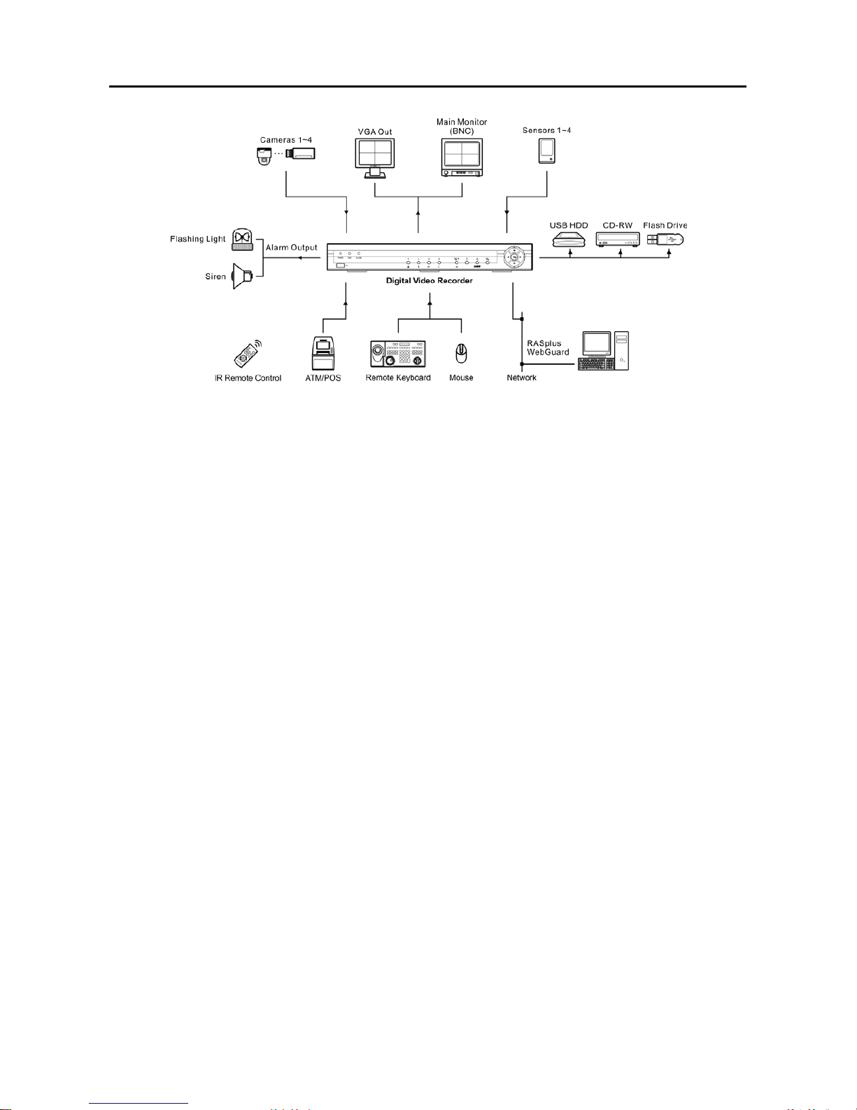
Figure 1 ─ Typical DVR installation.
4-Channel Digital Video Recorder
3
Chapter 2 ─ Installation
Package Contents
The package contains the following:
y Digital Video Recorder
y Power Cord
y User’s Manual (This Document)
y RAS Software CD and User’s Manual
y Infrared Remote Control
Required Installation Tools
No special tools are required to install the DVR. Refer to the installation manuals for the other items that make up
part of your system.
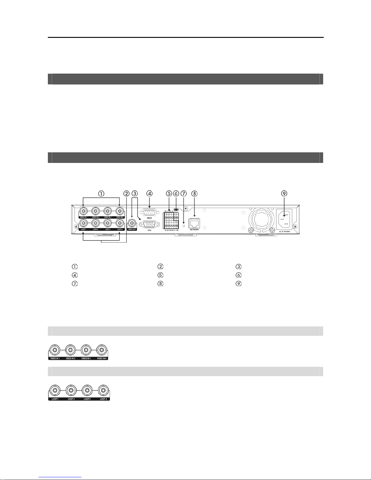
Figure 2 ─ DVR rear panel.
Video Input
Video Loop Through
Video Out
RS232 Port
Alarm Input/Output
RS485 Port
Factory Reset Switch
Network Port
Power Cord Connector
Your DVR can be used with either NTSC or PAL equipment.
NOTE: You cannot mix NTSC and PAL equipment. For example you cannot use a PAL camera and an NTSC
monitor.
Video Input
Video Loop Through
NOTE: The Loop BNC connectors are auto terminated. Do NOT connect a cable to the Loop BNC unless it is
connected to a terminated device because it will cause poor quality video.
Connect the coaxial cables from the video sources to the BNC Video In connectors.
If you would like to connect your video source to another device, you can use the Loop
BNC connectors.
User’s Manual
4
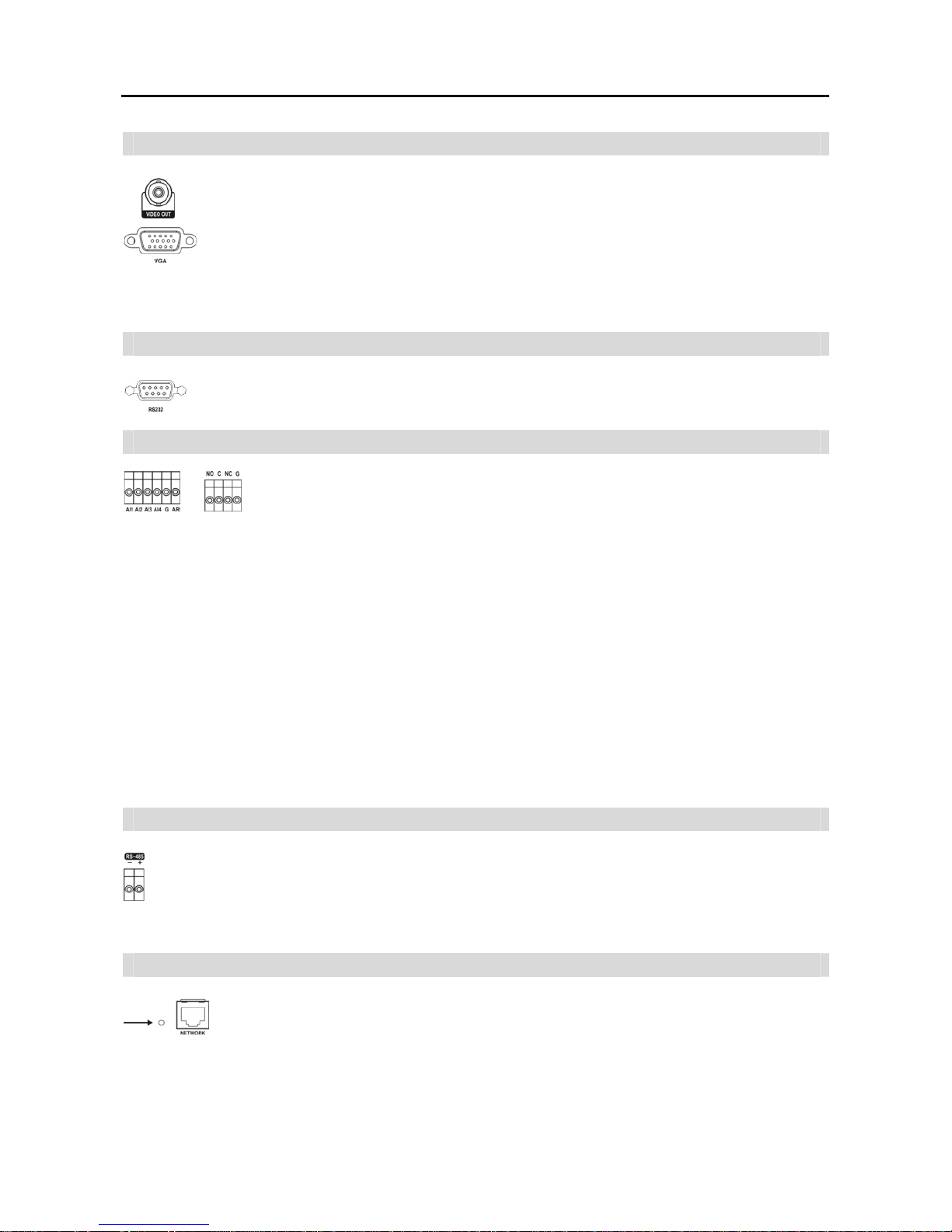
Video Out
Connect the main monitor to the Video Out connector.
A VGA connector is provided so that you can use a standard, multi-sync computer monitor as your
main monitor. Use the cable supplied with your monitor to connect it to the DVR. The VGA monitor
is automatically detected when you connect it.
NOTE: The Video Out (BNC) and VGA connectors may be connected to individual monitors for simultaneous
operation.
RS232 Port
An RS232 port is provided to connect a remote control keyboard.
Alarm Input/Output
NOTE: To make connections on the Alarm Connector Strip, press and hold the button
and insert the wire in the hole below the button. After releasing the button, tug gently
on the wire to make certain it is connected. To disconnect a wire, press and hold the
button above the wire and pull out the wire.
AI 1 to 4 (Alarm-In): You can use external devices to signal the DVR to react to events. Mechanical or electrical
switches can be wired to the AI (Alarm-In) and G (Ground) connectors. The threshold voltage is 4.3V and should be
stable at least 0.5 seconds to be detected. See Chapter 3 ─ Configuration for configuring alarm input.
G (Ground): Connect the ground side of the Alarm input and/or alarm output to the G connector.
NOTE: All the connectors marked G are common.
NC/NO (Relay Alarm Output): The DVR can activate external devices such as buzzers or lights. Connect the device
to the C (Common) and NC (Normally Closed) or C and NO (Normally Open) connectors. NC/NO is a relay output
which sinks 2A@125VAC and 1A@30VDC. See Chapter 3 ─ Configuration for configuring alarm output.
ARI (Alarm Reset In): An external signal to the Alarm Reset In can be used to reset both the Alarm Out signal and
the DVR’s internal buzzer. Mechanical or electrical switches can be wired to the ARI (Alarm Reset In) and G (Ground)
connectors. The threshold voltage is below 0.3V and should be stable at least 0.5 seconds to be detected. Connect the
wires to the ARI (Alarm Reset In) and G (Ground) connectors.
RS485 Port
The DVR can be controlled remotely by an external device or control system, such as a control keyboard,
using RS485 half-duplex serial communications signals. The RS485 connector can also be used to control
PTZ (pan, tilt, zoom) cameras. Connect RX-/ TX- and RX+/TX+ of the control system to the – and +
(respectively) of the DVR. See Chapter 3 ─ Configuration and the PTZ camera or remote controller
manufacture’s manual for configuring the RS485 connection.
Factory Reset Switch
The DVR has a Factory Reset switch to the left of the Network port on the rear panel. This
switch will only be used on the rare occasions that you want to return all the settings to the original
factory settings.
CAUTION: When using the Factory Reset, you will lose any settings you have saved.
4-Channel Digital Video Recorder
5
To reset the unit, you will need a straightened paperclip:
1. Turn the DVR off.
2. Poke the straightened paperclip in the unlabeled hole to the left of the Network port, and turn the DVR on.
3. Hold the reset switch until the DVR turns on and live monitoring screen appears.
4. Release the reset switch. All of the DVR’s settings are now at the original settings it had when it left the factory.
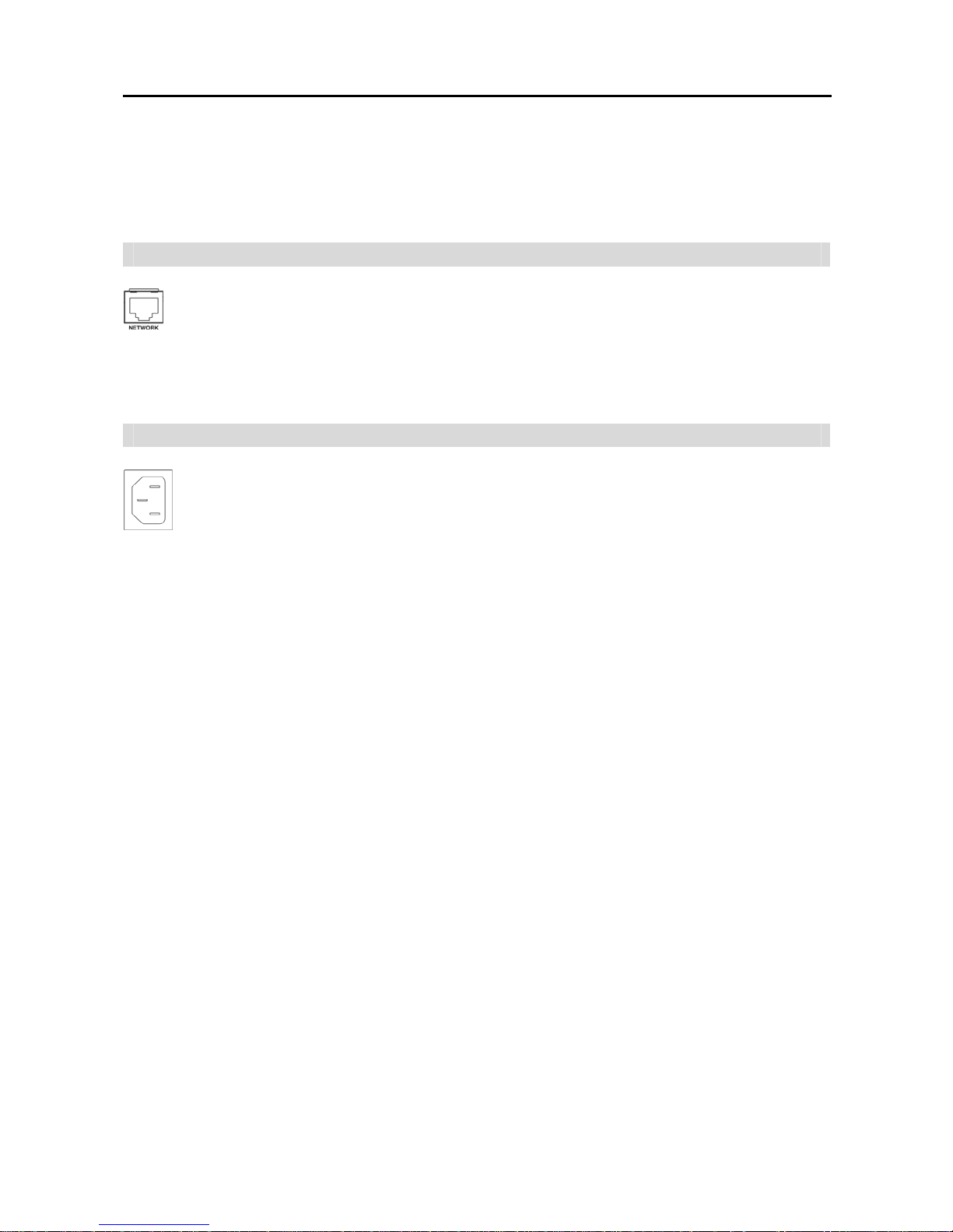
Network Port
The DVR can be networked using the 10/100Mb Ethernet connector. Connect a Cat5 cable with an
RJ-45 jack to the DVR connector. The DVR can be networked with a computer for remote monitoring,
searching, configuration and software upgrades. See Chapter 3 ─ Configuration for configuring the
Ethernet connections.
CAUTION: The network connector is not designed to be connected directly with cable or wire
intended for outdoor use.
Power Cord Connector
Connect the AC power cord to the DVR and then to a wall outlet.
WARNING: ROUTE POWER CORDS SO THAT THEY ARE NOT A TRIPPING HAZARD. MAKE
CERTAIN THE POWER CORD WILL NOT BE PINCHED OR ABRADED BY FURNITURE. DO NOT
INSTALL POWER CORDS UNDER RUGS OR CARPET.
THE POWER CORD HAS A GROUNDING PIN. IF YOUR POWER OUTLET DOES NOT HAVE A
GROUNDING PIN RECEPTACLE, DO NOT MODIFY THE PLUG. DO NOT OVERLOAD THE CIRCUIT
BY PLUGGING TOO MANY DEVICES IN TO ONE CIRCUIT.
Your DVR is now ready to operate. Refer to Chapter 3 ─ Configuration and Chapter 4 ─ Operation.
User’s Manual
6
Chapter 3 ─ Configuration
NOTE: Your DVR should be completely installed before proceeding. Refer to Chapter 2 ─ Installation.
Front Panel Controls
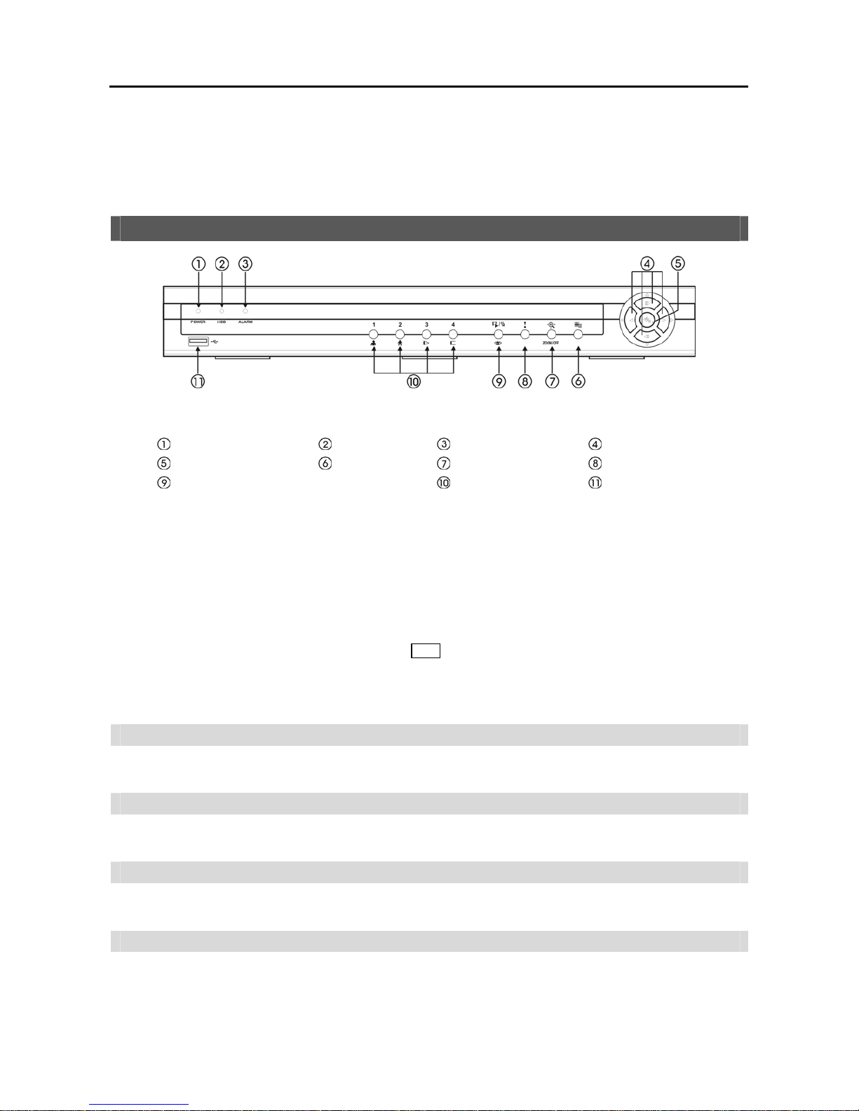
Figure 3 ─ DVR front panel.
Power LED
HDD LED
Alarm Out LED
Arrow Buttons
Enter/Pause Button
Menu Button
PTZ/Zoom Button
Panic Button
Playback Mode/Clip Copy Button
Camera Buttons
USB Connector
NOTE: A separate Alarm button is not provided. Pressing any button on the front panel or remote control resets
alarm output including the internal buzzer when the alarm is activated. However, when you are in the menu or
PTZ mode, you have to exit the menu or PTZ mode first to reset alarm output.
The front panel looks and operates much like a VCR combined with a multiplexer. Many of the buttons have multiple
functions. The buttons on the infrared remote control, while laid out differently, perform the same functions as those
on the front panel. The following describes each button and control. Take a few minutes to review the descriptions.
You will use these to initially set up your DVR and for daily operations.
NOTE: The infrared sensor is just to the right of the Menu button. Make certain that nothing blocks the sensor,
or the remote control will not function properly.
NOTE: You can also use a USB mouse (not supplied) to navigate through the screens and menus much like you
would on a computer.
POWER LED
The POWER LED is lit when the unit is On.
HDD LED
The HDD LED flickers when the DVR is recording or searching video on the hard disk drive.
ALARM LED
The ALARM LED is lit when alarm output or internal buzzer is activated.
Arrow Buttons
These buttons are used to navigate through menus and GUI. You can also use them to change numbers by highlighting
a number in the menu and using the Up and Down arrow buttons to increase or decrease the number’s value. These
buttons are also used to control Pan and Tilt when in the PTZ mode.
4-Channel Digital Video Recorder
7
In the playback mode, pressing the
button plays video backward at high speed. Pressing the button again toggles
the playback speed from , and , and the screen displays , and
respectively. While
playing video, pressing the
button plays video forward at high speed. Pressing the button again toggles the playback
speed from , , and , and the screen displays , , and
respectively. When in the pause
mode, pressing the
button moves to the next image and pressing the button moves to the previous image.
Enter/Pause Button
Pressing the
button selects a highlighted item or completes an entry that you have made during system setup.
In the live monitoring mode, pressing the
button freezes the current screen and the screen displays
icon. When
in the playback mode, pressing the
button pauses playing video.
Menu Button
Pressing the
Menu button enters the Setup screen. You will need to enter the authorized user and password to access
Setup. Pressing the button also closes the current menu or setup dialog box. In the Playback mode, pressing the button
displays the Search menu.
When in the live mode, pressing and holding the Menu button for three seconds or longer displays live channels
sequentially.
PTZ/Zoom Button
In the live monitoring mode, pressing the
PTZ/Zoom button enters the zoom mode, and pressing the button again exits
the zoom mode. When in the zoom mode, a rectangle displays on the screen. A rectangle shows the area that will be
enlarged. You can move the rectangle around using the arrow buttons. Pressing the
(Enter) button enlarges the
area in rectangle.
In the live monitoring mode, pressing and holding the PTZ/Zoom button for three seconds or longer enters the PTZ
mode, and pressing and holding the button again for three seconds or longer exits the PTZ mode. When in the PTZ
mode, pressing the arrow buttons or
Menu button allows you to control properly configured cameras.
Panic Button
Pressing the
Panic button starts panic recoding of all camera channels, and displays on the screen. Pressing the
button again will stop panic recording.
Playback Mode/Clip Copy Button
Pressing the
Playback Mode/Clip Copy button enters the playback mode, and pressing the button again exits the playback
mode. When entering the playback mode, video is paused. Pressing the arrow button plays back video at regular
speed. The screen displays when the DVR is in the Pause mode and the screen displays when the DVR is playing
back video. The button is also used to load a Preset View in the PTZ mode.
Pressing and holding the Playback Mode/Clip Copy button for three seconds or longer allows you to copy video clips.
Camera Buttons (1 to 4)
Pressing the individual camera buttons will cause the selected camera to display full screen, and pressing the button
again changes the display format to the quad (2x2) mode. Buttons 1 to 4 are also used to enter passwords.
In the PTZ mode, pressing the button 1 zooms in the screen and the button 2 zooms out the screen, and pressing the
button 3 focuses near and button 4 focuses far.
User’s Manual
8
USB Port
A USB port on the front panel is provided to connect external hard disk, CD-RW or flash drives for video clip copying
or system upgrades. Position external drives close enough to the DVR so that you can make the cable connections,
usually less than 6 feet. Use the USB cable provided with the hard disk drive to connect it to the DVR.
A USB mouse (not supplied) can be connected to the USB port. You can use the mouse to navigate through the screens
and menus much like you would on a computer.
A USB to Serial converter can be connected to the USB port. Multiple text-in devices can be used with a USB to Serial
converter.
ID Button on Remote Control
NOTE: For simplicity, the button descriptions in this manual refer to the front panel buttons.
Turning on the Power
Connecting the power cord to the DVR turns on the unit. The unit takes approximately 60 seconds to initialize.
Initial Unit Setup
Before using your DVR for the first time, you will want to establish the initial settings. This includes items such as
time and date, display language, camera, remote control, record mode, network and password. Your DVR can be set
up using various screens and dialog boxes.
Throughout the screens you will see
. Highlighting the and pressing the (Enter) button gives you the opportunity
to reset that screen to its default settings. After you are finished with any setup screen, you can highlight Save and
press the
button to save the changes and exit the screen. If you do not wish to save the changes, highlight Cancel
and press the
button to exit the screen.
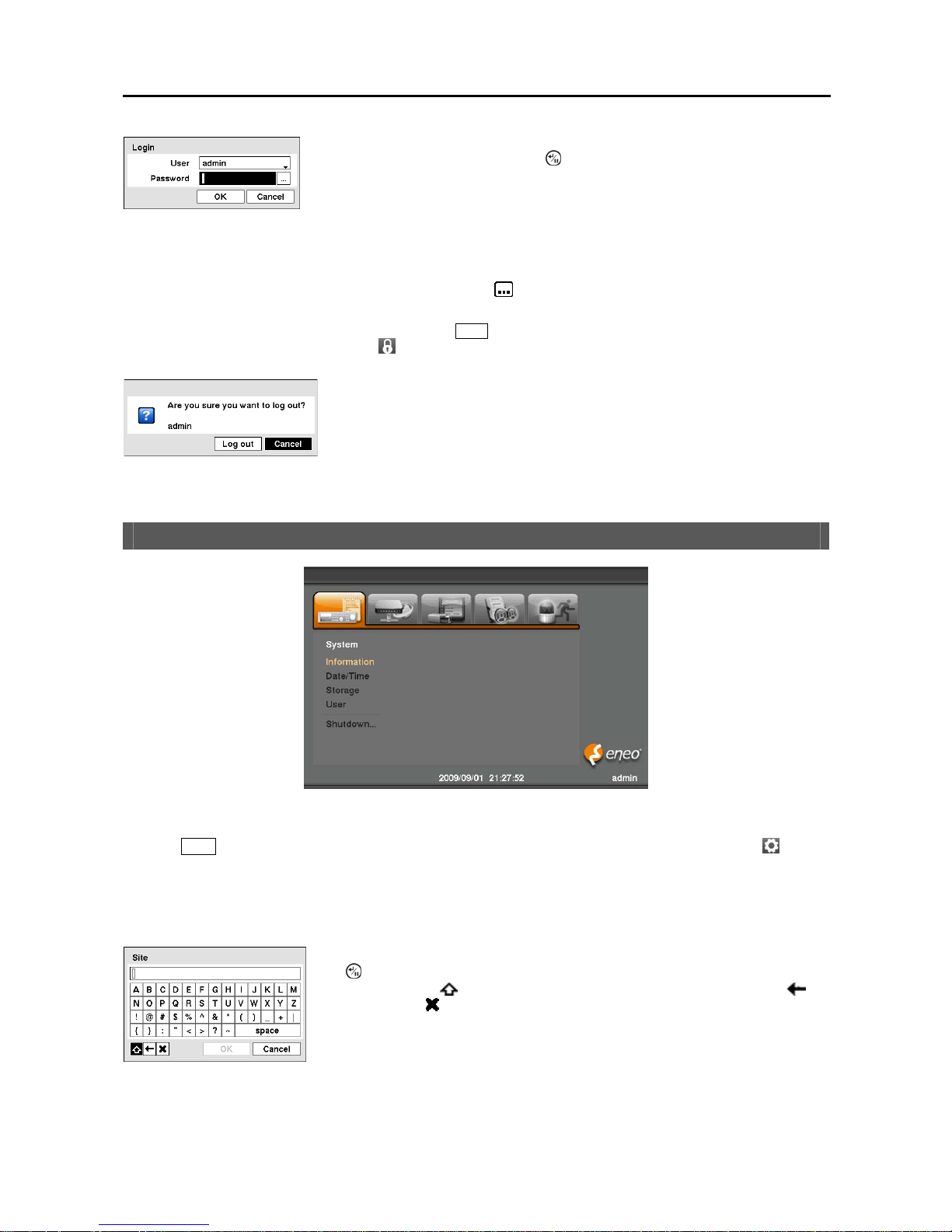
Press the
Menu button or move the mouse pointer to the top of the screen and then select (Login) in the Live
Monitoring menu to enter the setup screens. The Login screen appears.
Fi
g
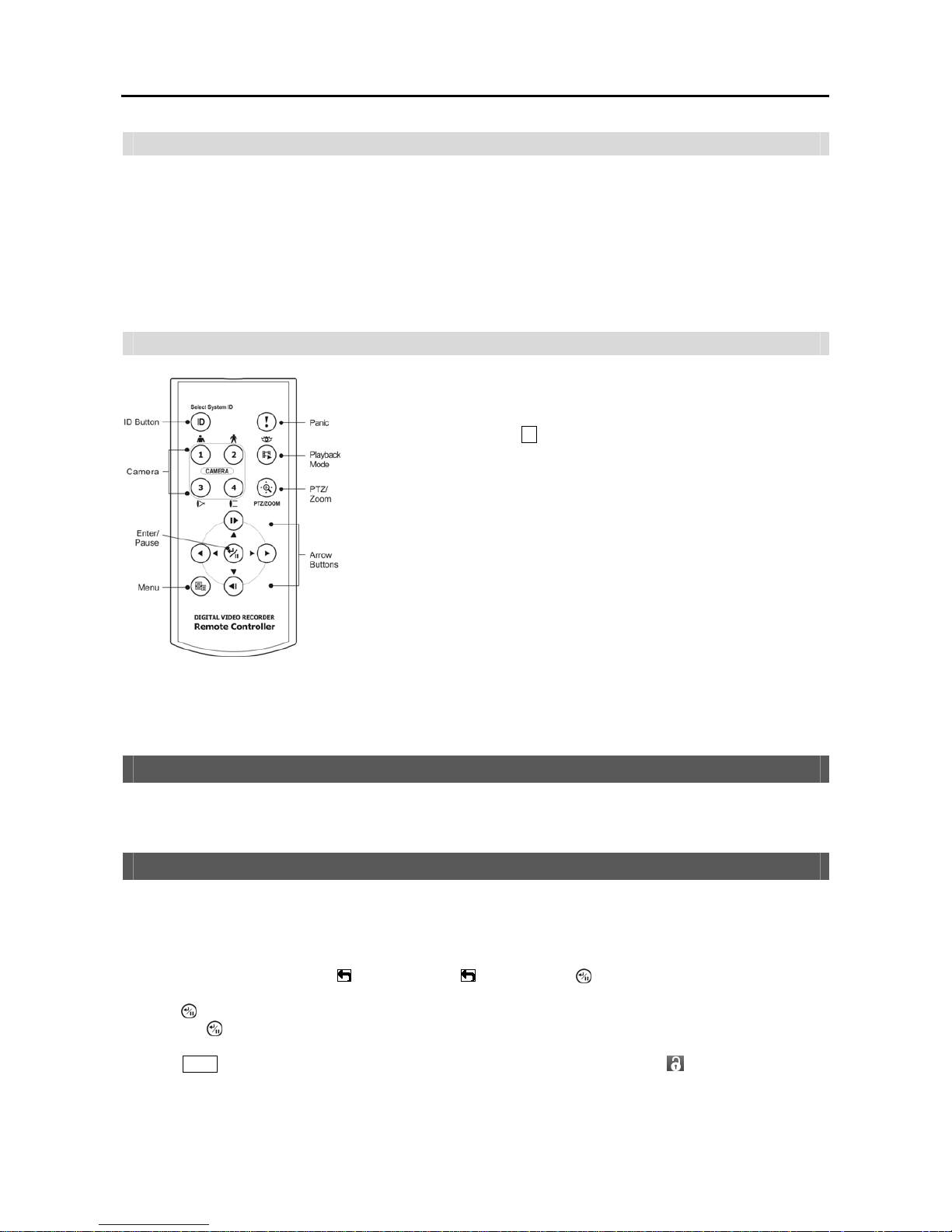
ure 4 ─ Infrared Remote Control.
If a DVR System ID is set to 0, the infrared remote control will control that DVR
without any additional operations. (Refer to the Information setup screen in this
chapter for further information on setting the System ID.) If the system ID is 1
to 4, you must to press the
ID button on the remote control and then press the
number button (1 to 4) in order to control that DVR. If the System ID of two
or more DVRs is set to 0, those DVRs will react to the infrared remote control
at the same time.
4-Channel Digital Video Recorder
9
NOTE: To assure the secure management of the system, setting up a password is strongly recommended.
NOTE: If you cannot use the front panel buttons, click the button using the mouse to enter a password, and
the virtual keyboard displays. See instructions below for using the virtual keyboard.
NOTE: To log the user out of the system, press the Menu button on the front panel or move the mouse pointer
to the top of the screen and then select (Logout) in the Live Monitoring menu. The Logout screen displays
asking you to confirm whether or not you want to log out the current user.
Figure 6 ─ Logout screen.
Setup Screen
Figure 7 ─ Setup screen.
Press the
Menu button on the front panel or move the mouse pointer to the top of the screen and then select (Setup)
in the Live Monitoring menu to enter the setup screen.
While setting up the DVR, there will be many opportunities to enter names and titles. When making these entries, a
Virtual Keyboard will appear.
Fi
g
ure 5 ─ Login screen.
Select a User and enter the password by pressing the appropriate combination of
Camera number buttons and then the
button. There is no default password when
logging in the admin user for the first time.
Use the arrow keys to highlight the character you want in the name or title and press
the
button. That character appears in the title bar and the cursor moves to the next
position. Pressing
toggles between the upper and lower case keyboards,
backspaces, and
deletes entered characters. You can use up to 31 characters
including spaces in your title.
Special characters can be created using ^ and a capital letter; e.g. ^J for NL (New Line),
^M for CR (Carriage Return). Special characters are commonly used by text input
devices and will be useful when performing Text-In Searches.
User’s Manual
10
System Setup
Figure 8 ─ System menu.
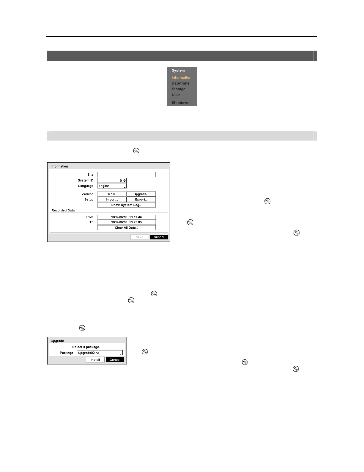
Information
Highlight Information and press the
button. The Information setup screen appears.
NOTE: The System ID number is used to identify the unit when it is connected with other DVRs through the
RS485 port. You cannot use the same ID number for two or more DVRs that are in the same RS485 network. It
is possible to have multiple DVRs with System ID 0 that are in the same area as long as they are not part of an
RS485 network. If this is the case, all will be controlled at the same time when using the infrared remote control.
Highlight the box beside Language and press button. A drop-down menu displays the available languages. Highlight
the desired language and press the
button.
The box beside Version displays the software version of the DVR.
To upgrade the software, connect a USB device containing the upgrade package file to the DVR. Highlight Upgrade…
and press the
button. The Upgrade screen appears.
CAUTION: The system restarts automatically after completing the upgrade, and it takes approximately
one minute to restart. Do NOT remove the USB device until the DVR restarts, otherwise the system
upgrade will not be completed properly.
CAUTION: The USB device must be FAT16 or FAT32 format.
Figure 9 ─ Information setup screen.
In the Information screen, you can name the site location,
assign a System ID number, select the language the screens
are displayed in, display software version number, upgrade
the software, show the System Log, display recorded time
data, and clear all data.
Highlight the Site box and press the button. A virtual
keyboard appears that you can use to enter a Site Name.
Once you have entered your title, highlight Close and press
the
button.
Highlight the box beside System ID and press the button.
Change the number by highlighting it and using the Up and
Down arrow buttons to increase and decrease the number from
0 to 99.
The screen displays the upgrade package file names that are available. The “.rui”
indicates that the file is for software upgrades. Select the desired file and press
the
button.
Highlighting the Install button and pressing the button will install the selected
software package. Highlighting the Cancel button and pressing the
button
will close the window without upgrading the software. If the upgrade package
file is not installed on the DVR properly, you will get an error message.
4-Channel Digital Video Recorder
11
NOTE: Even after changing the DVR settings by importing saved settings, the time-related settings (Date/Time,
Time Zone and Daylight Saving Time) will NOT be changed.
CAUTION: The USB device must be FAT16 or FAT32 format.
Highlight Show System Log… and press the
button to display the System Log.
The box beside Recorded Data – From / To displays the time information of recorded data.
Highlighting Clear All Data… and pressing the button will clear all video data. You will be asked to verify that
you wish to clear all data before the DVR erases the video data. Clear All Data… will not clear the System Log.
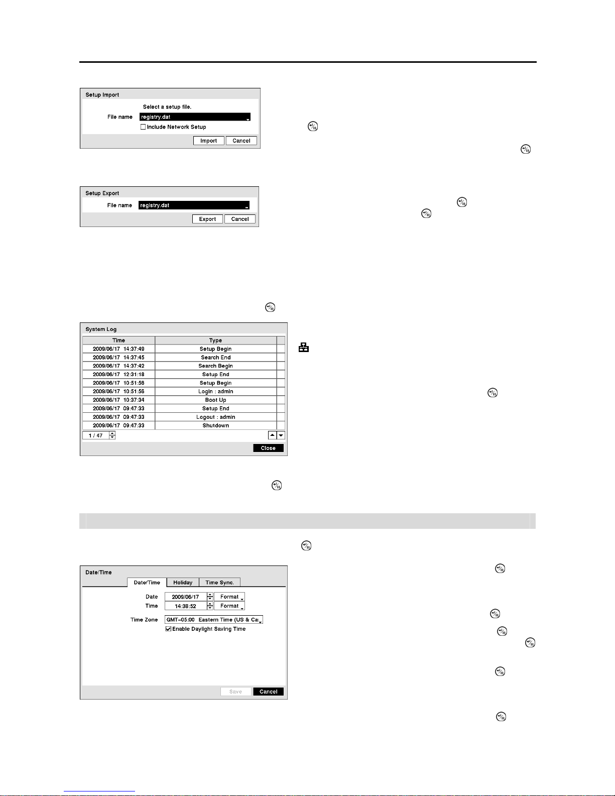
Date/Time
Highlight Date/Time in the System menu and press the
button. The Date/Time setup screen appears.
You can import saved DVR settings or export the current DVR settings.
To import saved DVR settings, connect the USB device containing
the setup file (.dat) to the DVR. Highlight Setup – Import… and
press the
button. Select the desired setup file and press the Import
button to import the selected settings and change the DVR settings
accordingly. Highlight Include Network Setup and press the
button to toggle between On and Off. When set to Off, the network
settings will not be changed.
To export the current DVR settings, connect the USB device to the
DVR. Highlight Setup – Export… and press the
button. Highlight
the box beside File name and press the
button. A virtual keyboard
allows you to enter the file name. Selecting Export will save the current
settings in .dat file format on the USB device.
The System Log screen lists system activities (up to 5,000 from
the latest) that have occurred along with the time and date. The
icon will be displayed in the last column for system activities
of the remote site. You can scroll through the log pages by
using the Up and Down arrows, or you can go directly to a log
page by entering the log page number in the box at the bottom
left of the screen. Highlight Close and press the
button to
exit the screen.
Figure 10 ─ Date/Time setup screen.
Highlight the first box beside Date and press the
button.
The individual sections of the date will highlight. Use the Up
and Down arrow buttons to change the number. Use the Left
and Right arrow buttons to move between month, date and
year. Once you have the correct date, press the
button.
Highlight the Format box beside Date and press the button.
Select from the three available date formats and press the
button to save your selected format.
Highlight the first box beside Time and press the button.
The individual sections of the time will highlight. Use the Up
and Down arrow buttons to change the number. Use the Left
and Right arrow buttons to move between hour, minutes and
seconds. Once you have the correct time, press the
button.

User’s Manual
12
Highlight the Format box beside Time and press the
button. Select from the three available time formats and press
the
button to save your selected format.
NOTE: The clock will not start running until you have highlighted Save and pressed the button.
Highlight the box beside Time Zone and press the button. Select your time zone from the list and press the button.
Highlight Use Daylight Saving Time and press the button. Pressing the button toggles between On and Off.
Highlight the Holiday tab, and the Holiday setup screen appears
Highlighting the Time Sync. tab causes the Time Sync. setup screen to display. You can set up time synchronization
between the DVR and standard time servers that are available in most time zones and countries, or between the DVR
and another DVR.
Last Sync-Time displays the last time the DVR was synchronized with the time server.
Highlight Run as Server and press the button. Pressing the button toggles between On and Off. When it is
On, the DVR you are setting up will run as a time server.
Figure 11 ─ Holiday setup screen.
You can set up holidays by highlighting + and pressing the
button. The current date appears.
Highlight the month and day and change them by using the
Up and Down arrow buttons. Press the
button to add the
date. Dates can be deleted by highlighting the
beside the
date and pressing the
button.
NOTE: Holidays that do not fall on the same date each
year should be updated once the current year’s holiday
has passed.
Fi
g
ure 12 ─ Time Sync. setup screen.
Highlight the box beside Automatic Sync. and press the
button. This toggles between On and Off.
Highlight the box beside Time Server and press the button.
A virtual keyboard appears that you can use to enter the IP
address or domain name of the time server.
NOTE: You can use the domain name instead of IP address
if you already set up the DNS Server when setting up the
LAN.
Highlight the box beside Interval and press the button. Set
the time interval for synchronization from 30 minutes to 1 day
at various time intervals.
4-Channel Digital Video Recorder
13
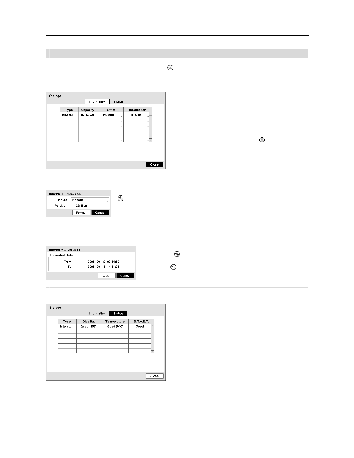
Storage
Highlight Storage in the System menu and press the
button. The Storage setup screen appears and displays
information about the DVR’s storage devices.
The Information column displays whether the device is being used or not. Other indicates the device has been used
for another DVR.
Highlight the Status tab, and the Storage Status setup screen displays.
Figure 13 ─ Storage Information setup screen.
The information in the Type column describes the storage
device.
The capacity of the storage device is displayed in the Capacity
column.
The Format column displays whether the device is used for
recording (Record) or not (Not Using). Not formatted
indicates the device is not formatted.
indicates when the
device has temporary space set aside so that video clips can
be saved on a CD-RW.
Highlight the box in the Format column for the desired storage device and press the
button. You will be able to format the device for recording. When selecting Not
Using from Use As and highlighting the Format button, the device will not be used
for recording. You can also set aside space to store temporary files for CD burning by
selecting Partition – CD Burn.
Highlight the box in the Information column for the desired storage device
and press the
button. The box beside Recorded Data – From / To
displays the time information of recorded data. Highlighting Clear and
pressing the
button will clear all video data. You will be asked to verify
that you wish to clear all data before the DVR erases the video data. Clear
All Data… will not clear the System Log.
Figure 14 ─ Storage Status setup screen.
The Type column displays the type of storage device.
The Disk Bad column displays the percentage of bad sectors.
Not formatted indicates the device is not formatted.
The Temperature column displays the temperature of the
storage device.
y Good – The temperature is normal.
y Bad – The temperature is 70oC (158oF) or higher.
y N/A – The DVR cannot read the temperature.
The S.M.A.R.T. column displays “Good”, “Bad” or “N/A”,
depending on storage conditions.
y Good – The storage condition is normal.
y Bad – Data cannot be written on or read from the storage
device.
y N/A – Storage conditions are normal, however, the S.M.A.R.T.
monitoring is not working or supported.
User’s Manual
14
NOTE: When the S.M.A.R.T. displays Bad, the screen displays a message box. Once the “Bad” message displays,
replacing the hard disk drive is recommended, usually within 24 hours.
NOTE: Temperature and S.M.A.R.T. information will be available only for internal hard disk drives supporting
the SMART (Self-Monitoring Analysis and Reporting Technology) monitoring program.
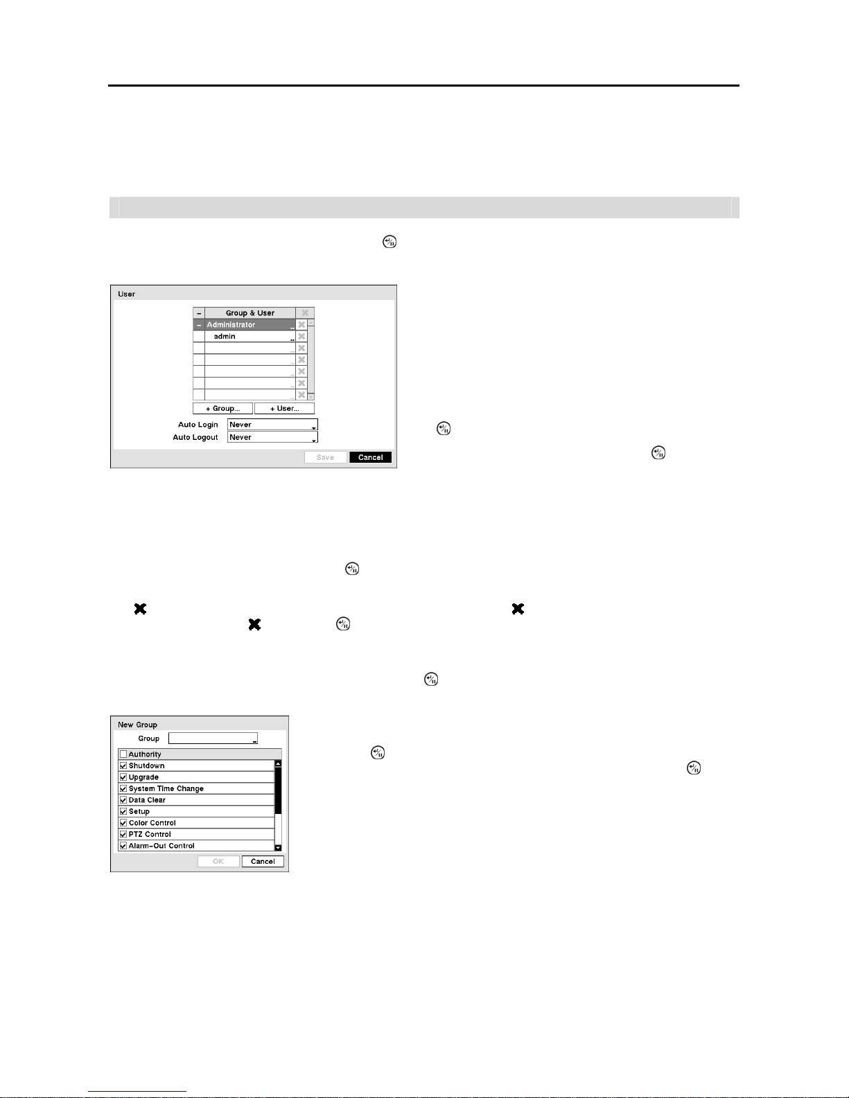
User
Highlight User in the System menu and press the
button. The User setup screen displays the authorized groups
and users. You can add and delete groups and users. When adding a group, you can assign authority levels to the group.
CAUTION: Write down the new password and save it in a secure place. If the password is forgotten,
the unit must be reset using the Factory Reset Button and all data settings will be lost.
Highlighting a User Name and pressing the
button allows you to add or change the password assigned to that user.
You can also change the group to which the user is assigned.
The column can be used to delete a User Name or an entire Group. If the is grayed out, that Group or User cannot
be deleted. Highlight the
and press the button. You will be asked to confirm that you want to delete the User or
Group. To delete the User currently logged into the DVR on a local system or a PC running RAS, log the user out of
the system first and then delete the user.
To add a Group, highlight the + Group… box and press the button. A virtual keyboard appears allowing you to enter
the Group name.
y Data Clear – The user can clear all video data or format disks on a local system or a PC running RAS.
y Setup – The user without Setup authority cannot establish any system settings excluding system shutdown and logout
on a local system or a PC running RAS.
y Color Control – The user can control brightness, contrast, hue and saturation for cameras on a local system or a PC running RAS.
y PTZ Control – The user can control the PTZ camera on a local system or a PC running RAS.
y Alarm-Out Control – The user can reset the DVR’s outputs including the internal buzzer during an alarm by pressing
any button on the front panel or remote control on a local system or alarm-out control button on a PC running RAS.
Fi
g
ure 15 ─ User setup screen.
The +/- column is used to collapse and expand user groups.
If there is a + or – in this column, it indicates the item is a
Group Name. If there is a – in front of the Group Name, it
indicates that the group has been “expanded” and all of the
User Names within that group are displayed below the Group
Name. If there is a + in front of the Group Name, it indicates
that the group has been “collapsed” and all of the User Names
within that group are hidden. To collapse or expand a group,
highlight the +/- column in front of the desired group and press
the button.
Highlighting a Group Name and pressing the button allows
you to change the authority levels assigned to the group.
You can use up to 15 characters including spaces in the group name. Enter the
name and assign authority levels to the group. Highlighting the Authority box and
pressing the
button will toggle between all authority levels being turned On and
Off. Highlighting the individual authority level boxes and pressing the
button
will toggle between that authority level being turned On and Off. The authority
levels that can be turned On and Off are:
y Shutdown – The user can shut the system down on a local system.
y Upgrade – The user can upgrade the software on a local system or a PC running RAS.
y System Time Change – The user can change the system date and time on a local
system or a PC running RAS.
 Loading...