

Eneo BCR-3004, BCR-3008, BCR-3016 Operating Instructions Manual
Operating Instructions
Digital Video Recorder
BCR-3004, BCR-3008 und BCR-3016
1

Contents
1. Safety Instructions / Maintenance ....................................................................................................................... 3
2. Product Features ................................................................................................................................................
3. Function of Buttons ............................................................................................................................................
3.1 Front Panel ................................................................................................................................................5
3.2 Rear View ..................................................................................................................................................7
3.3 Connector Pin ........................................................................................................................................... 8
4. Installation ....................................................................................................................................................... 10
4.1 Connections ............................................................................................................................................ 10
4.2 Hardware Installation ..............................................................................................................................11
5. Display Configuration .......................................................................................................................................
5.1 Current Status ......................................................................................................................................... 17
5.2 Display Status ......................................................................................................................................... 17
5.3 Popup Menu ............................................................................................................................................ 18
5.4 Toolbar .................................................................................................................................................... 27
6. DVR Setup ........................................................................................................................................................
6.1 Operation ................................................................................................................................................ 28
6.2 Display .................................................................................................................................................... 32
6.3 Record .................................................................................................................................................... 38
6.4 Event ...................................................................................................................................................... 44
6.5 Network .................................................................................................................................................. 48
6.6 System ................................................................................................................................................... 52
7. DVR Operation ..................................................................................................................................................
7.1 Live Monitoring ....................................................................................................................................... 59
7.2 Event Monitoring ..................................................................................................................................... 63
7.3 Mouse Operation ..................................................................................................................................... 64
7.4 Record .................................................................................................................................................... 65
7.5 Search .................................................................................................................................................... 65
7.6 Playback ................................................................................................................................................. 69
7.7 Network Setup ........................................................................................................................................ 70
8. Integrated Remote Station ................................................................................................................................
8.1. IRS Setup ................................................................................................................................................ 80
8.2 IRS Operation .......................................................................................................................................... 82
8.3 Remote Viewer ........................................................................................................................................ 85
8.4 Search .................................................................................................................................................... 86
8.5 Backup ...................................................................................................................................................88
8.6 Player ..................................................................................................................................................... 91
9. Frequently Asked Questions ..............................................................................................................................
10. Technical Specifications ...................................................................................................................................
Appendix A – Factory Default Value ..........................................................................................................................
Appendix B – Remote Control ................................................................................................................................ 10
4
5
16
28
59
80
93
94
96
1
2

1. Safety Instructions / Maintenance
• Read these safety instructions and the operation manual first before you install and commission the unit.
• Keep the manual in a safe place for later reference.
• The system may only be commissioned and maintained by personnel authorized to do this and it must only be
carried out in accordance with relevant standards and guidelines.
• Never cover the ventilation slots to avoid overheating.
• Never insert metal objects or any other items into the vents. This may permanently damage the unit.
• Protect your unit from contamination with water and humidity to prevent it from permanent damage.
Never switch the unit on when it gets wet.
Have it checked at an authorized service center in this case.
• Never operate the units outside of the specifications as this may prevent their functioning.
• Do not operate the unit beyond their specified temperature, humidity or power ratings. Operate the unit only at a
temperature range of +5°C to +40°C and at a humidity of max. 80%.
• The unit should be protected against excessive heat, dust, damp and vibration.
• Do not place any heavy objects on the unit.
• To disconnect the power cord of the unit, pull it out by the plug. Never pull the cord itself.
• Pay attention when laying the connection cable and observe that the cable is not subject to heavy loads, kinks, or
damage and no moisture can get in.
Do not attempt to disassemble the camera board from the dome.
• Contact your local dealer in case of malfunction.
• The connection cable should only be changed by Videor E. Hartig GmbH.
• The warranty becomes void if repairs are undertaken by unauthorized persons. Do not open the housing.
• Installation, maintenance and repair have to be carried out only by authorized service centers.
Before opening the cover disconnect the unit from mains input.
• Only use original parts and original accessories from Videor E. Hartig GmbH.
• Do not use strong or abrasive detergents when cleaning the dome. Use a dry cloth to clean the dome surface. In
case the dirt is hard to remove, use a mild detergent and wipe gently.
NOTE: This is a class A digital device.
This digital device can cause harmful interference in a residential area; in this case the user may be
required to take appropriate corrective action at his/her own expense.
Betriebsanleitung
Installation and Operating Instructions
Mode d’emploi
Instrucciones de manejo
⇒
3

2. Product Features
• BCR-3004: 4 Loop-through Video Inputs / VGA, Composite Outputs
BCR-3008: 8 Loop-through Video Inputs / VGA, Composite Outputs
BCR-3016: 16 Loop-through Video Inputs / VGA, Composite Outputs
• Alarm Inputs / Outputs
• Pentaplex Operation
• MPEG-4 Video Compression
• Recording Speed: BCR-3004: 100 ips. max.
BCR-3008, BCR-3016: 200 ips. max.
• Video Resolution 704x576 Pixels max.
• BCR-3004, BCR-3008, BCR-3016: 320GByte SATA HDD (2 Hard Disks max.)
BCR-3004, BCR-3008, BCR-3016: 820GByte SATA HDD (no HDD extention possible)
BCR-3004, BCR-3008, BCR-3016: 1.07, resp. 1.32TByte SATA HDD (no HDD extention possible)
• Recording Modes: Time, Motion, Alarm and Emergency
• Secondary Storage / Archiving via USB and DV-RW
• Multiple Language On-screen Menu Control
• RS-232/RS-485 Ports (PC and Telemetry Control)
• Ethernet Connectivity (Remote Viewer Program incl.)
Enhanced Viewer Software included.
Features: limited DVR Setup. Backup: File export to local PC by Network (MPEG-4). CMS: Set-up of different groups
and site maps, Event list, PTZ control, Drag&drop function for single cameras (Live), Playback with search function
(by time & event)
Parts supplied
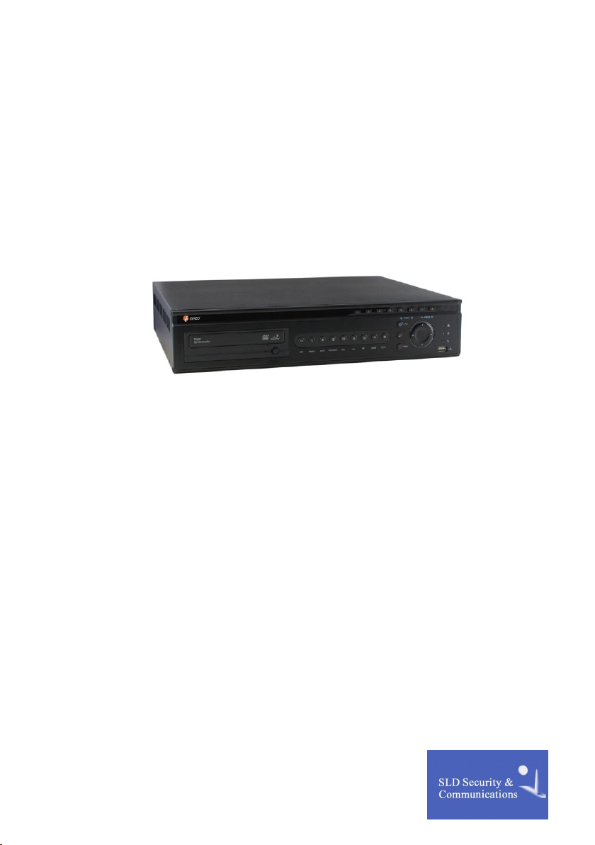
• Digital Video Recorder
• Mouse
• IR Remote control
• Power supply unit
• 19” rack mount kit
• Remote Viewer Software
• Operating and instruction manual
4
3. Function of Buttons
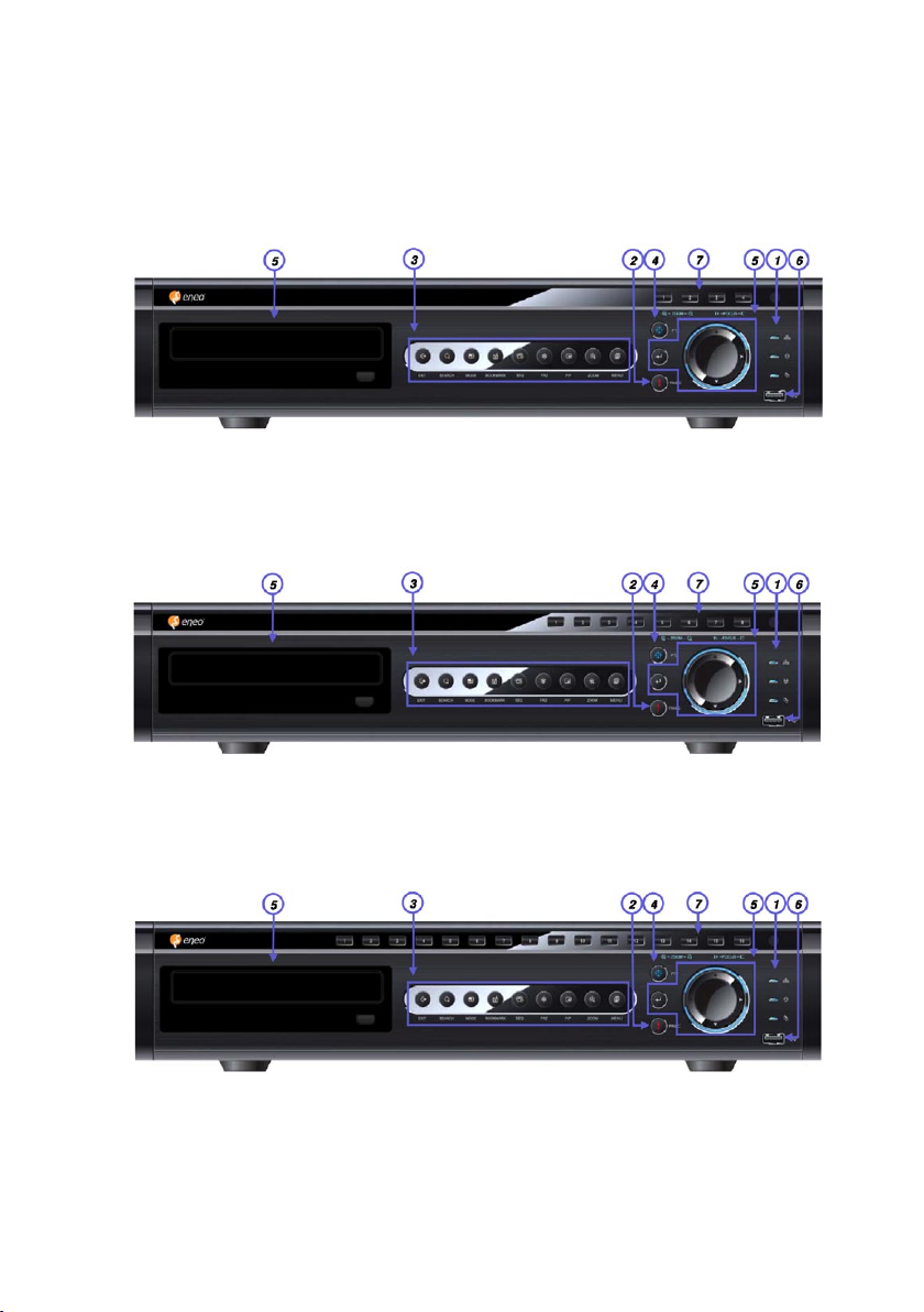
3.1 Front Panel
4 Channel DVR Layout
8 Channel DVR Layout
16 Channel DVR Layout
5

NOTE: This manual covers the 4 channel, 8 channel and 16 channel digital video recorders.
For simplicity, the illustrations and descriptions in this manual refer to the 16 channel model.
No. Name Description
1 LED
2 PANIC
3 Function Key
4 PTZ
5 Direction Key (Example Operational condition under Playback mode)
6 USB Port
7 Camera Selection /
PTZ Control
8 CD/DVD-RW
Indicating operation status
Emergency recording (Enables pre-configured force recording)
EXIT Button used to stop PANIC mode, Play Back mode
SEARCH Search recorded data on HDD
MODE Switch screen division from full screen to 16 split screen
(in 1, 4, 9, 16 sequence)
BOOKMARK Bookmark during Playback
SEQ Auto camera image sequence in full screen mode
FRZ Freeze live image
PIP Picture In Picture mode
ZOOM Zoom image
MENU Enter SYSTEM MENU
Switch LIVE mode to PTZ control mode
ENTER PAUSE
LEFT Reverse playback
RIGHT Playback
UP Increase playback speed
DOWN Decrease playback speed
Port available for USB Memory devices
1~16 Button: Select camera channel in full screen mode
ZOOM, + ZOOM IN
ZOOM, - ZOOM OUT
FOCUS, + Focus Far
FOCUS, - Focus Near
For optical media backup
6
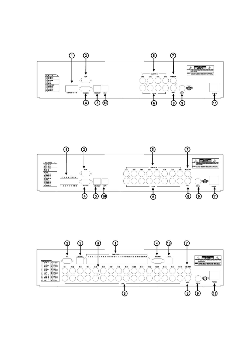
3.2 Rear View
4 Channel DVR
8 Channel DVR
16 Channel DVR
7
NOTE: You cannot mix NTSC and PAL equipment. For example you cannot use a PAL camera and a NTSC
monitor.
No. Name Description
1 RS485
RELAY Output
SENSOR Input
2 VGA
3 ETHERNET
4 RS232C
5 CAMERA
6 LOOP
7 MAIN MONITOR
8 SPOT (Call monitor)
9 DC Power
10 PS2 Mouse
11 POWER SWITCH
Terminal block type (for PTZ and other External Devices)
Terminal block type (Relay Output)
Terminal block type (Sensor Input)
DE-15 female socket (VGA Output to CRT or TFT LCD Monitors)
RJ-45 Type connector (10/100Mbps)
D-sub 9 pin female (External devices for to control DVR)
Auto detecting NTSC/PAL Cameras ( BNC type 1.0Vp-p/75 ohm)
Camera Loop out (BNC type 1.0Vp-p/75 ohm)
Auto detecting NTSC/PAL Composite Monitor (BNC type 1.0Vp-p/75 ohm)
Auto detecting NTSC/PAL Composite Monitor (BNC type 1.0Vp-p/75 ohm)
DC 12V 6.67A Adaptor
PS2 connection port (for mouse input only)
Power ON/OFF Switch
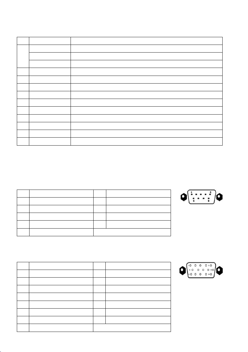
3.3 Connector Pin
3.3.1 RS-232
No. Details No. Details
1
N/C (Normal Close)
2
RxD (Data Transmission)
3
TxD (Data Transmission)
4
N/C (Normal Close)
5
GND (Ground)
6
N/C (Normal Close)
7
N/C (Normal Close)
8
N/C (Normal Close)
9
N/C (Normal Close)
3.3.2 VGA
No. Details No. Details
1
Red Sig. (75ohms, 0.7 Vp-p)
2
Green Sig. (75ohms, 0.7 Vp-p)
3
Blue Sig. (75ohms, 0.7 Vp-p)
4
N/C (Normal Close)
5
GND (Ground)
6
GND (Ground)
7
GND (Ground)
8
GND (Ground)
9
N/C (Normal Close)
10
GND (Ground)
11
GND (Ground)
12
N/C (Normal Close)
13
HYNC (Horizontal Sync.)
14
VSYNC (Vertical Sync.)
15
N/C (Normal Close)
8
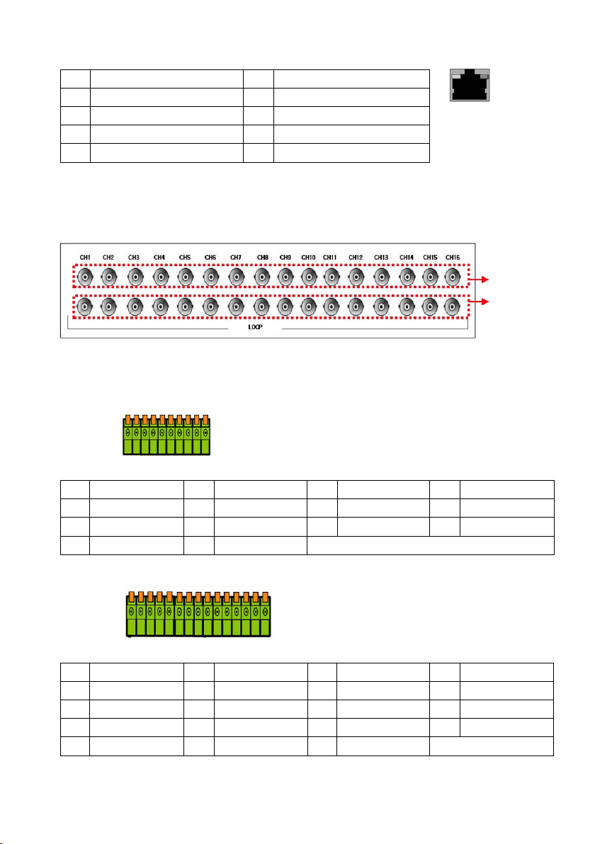
3.3.3 LAN
No. Details No. Details
1
TX+ (Data Transmission)
2
TX- (Data Transmission)
3
RX+ (Data Transmission)
4
N/C (Normal Close)
5
N/C (Normal Close)
6
R/X- (Data Transmission)
7
N/C (Normal Close)
8
N/C (Normal Close)
3.3.4 CAMERA input & LOOP output
Camera Input
Loop Output
3.3.5 External Device Connection: Connection with PTZ camera, sensor, relay output
4 Channel
No. Details No. Details No. Details No. Details
1
RS485 D-
5
AL NO
9
ALARM D2
8 Channel
No. Details No. Details No. Details No. Details
1
RS485 D-
5
AL NO
9
ALARM D6
13
ALARM D3
2
6
10
2
6
10
14
RS485 D+
ALARM GND
ALARM D1
RS485 D+
GND
ALARM D5
ALARM D2
3
AL COMM
7
ALARM D4
3
AL COMM
7
ALARM D8
11
GND
15
ALARM D1
9
4
8
4
8
12
AL NC
ALARM D3
AL NC
ALARM D7
ALARM D4
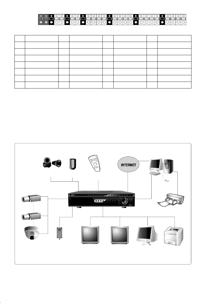
16 Channel
No. Details No. Details No. Details No. Details
1
5
9
13
17
21
25
RS485 D-
AL NO2
GND
ALARM 13
ALARM 10
ALARM 7
ALARM 4
2
6
10
14
18
22
26
RS485 D+
AL COMM1
ALARM 16
GND
ALARM 9
ALARM 6
ALARM 3
3
7
11
15
19
23
27
AL COMM2
AL NC1
ALARM 15
ALARM 12
GND
ALARM 5
ALARM 2
4
8
12
16
20
24
28
AL NC2
AL NO1
ALARM 14
ALARM 11
ALARM 8
GND
ALARM 1
4. Installation
4.1 Connections
TCP/IP
Alarm
Camera
P/T Camera
Typical DVR connection examples
RX Box
Sensor
Remote Control
SPOT Monitor Composite
TCP/IP
RS-232C
Printer
Monitor
10
VGA Monitor
TFT-LCD Monitor
Video Printer
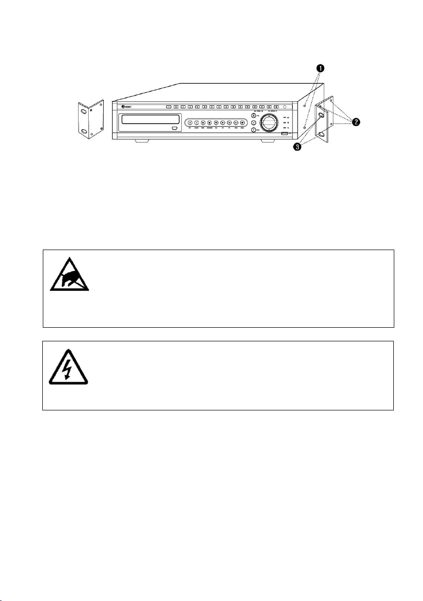
4.2 Hardware Installation
4.2.1 Rack Mounting
1. Remove the cross head screws (four on each side) located near the front panel on the right and left side of the unit.
2. Secure the rack mount brackets to each side using same cross head screws that were just removed.
3. Install the unit into the 19 inch wide rack (follow the rack manufacturer’s instructions.)
4.2.2 HDD (Hard Disk Drive) connection
CAUTION !
Electrostatic discharges
Any electrostatic energy coming in contact with the hard disk or other sensitive internal parts
can damage them permanently. Improper handling could void the warranty of the hard disk.
When working with electrostatic sensitive devices such as a hard disk or the Divar unit, make
sure you use a static-free workstation.
DANGER !
Electrical voltage
Risk of electric shock
Before installation of the hard disk, unplug the power cord of the DVR and wait for at least
30 seconds.
1. Connect Main Board and HDD1 using SATA cable and HDD power cable.
2. For the single Hard Drive installation make sure you install the HDD onto HDD1 location.
3. For the two Hard Disk Drive installation make sure you install the first HDD onto HDD1 location and then install the
second HDD onto HDD2 location.
4. Install the HDD(s) to the HDD bracket by using the bolts (included in the package).
5. Attach the HDD bracket into the bottom case.
(Refer to the pictorial examples on following page.)
11
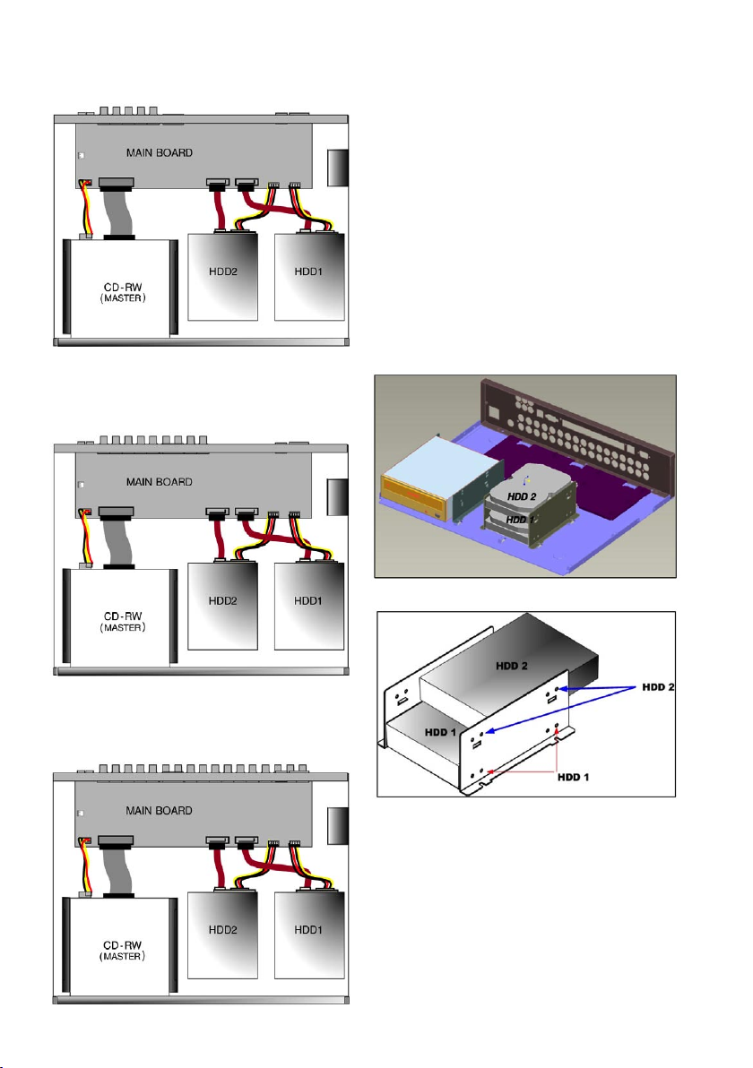
4 Channel
8 Channel
HDD Cable Connectiom
HDD Fix
HDD Cable Connectiom
16 Channel
HDD Cable Connectiom
12
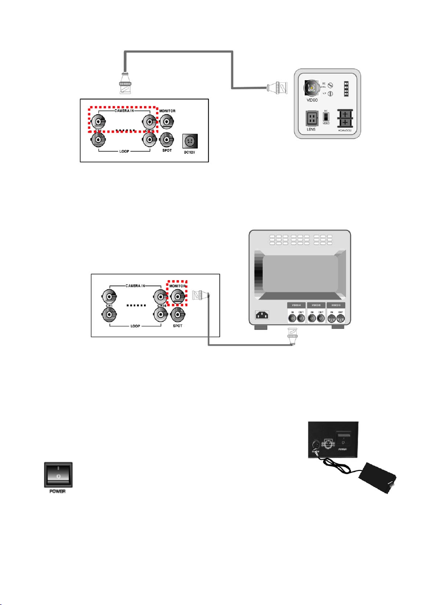
4.2.3 Camera
Connect cameras to the camera input on rear panel of DVR marked CAMERA IN.
4.2.4 Monitor
Rear view of camera
Connect the video output marked MONITOR to VIDEO-IN of Main Monitor.
4.2.5 Power Cable
Connect DC 12V, 6.67A Adaptor to the back side of Power Jack for proper operation
of 2HDDs and optical drive.
Before turning on, be sure all necessary devices such as Power
adaptor, cameras and Monitor are connected properly to DVR!
NOTE: This unit is for 12VDC. Inadequate supply of power may cause breakdown.
Must use UL approved surge protector and highly recommend UL approved UPS power strip for
unwanted shutdown of the DVR unit.
Improper shutdown and power surge will damage the DVR unit.
Be sure to power off DVR when connecting external devices.
13
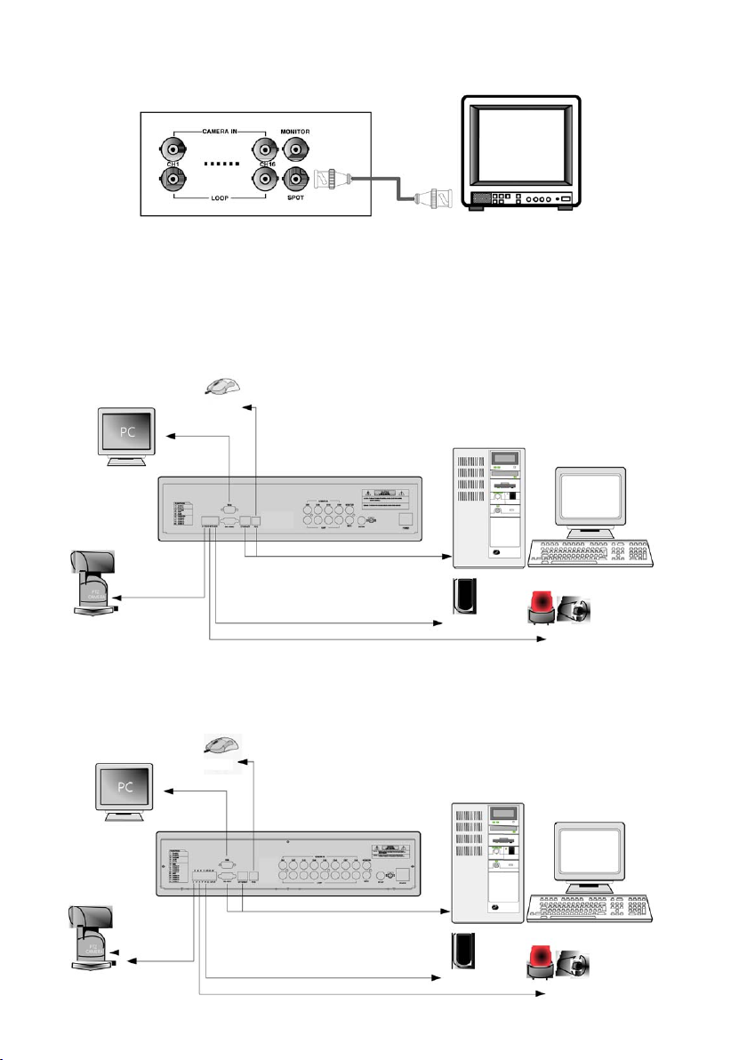
4.2.6 SPOT Monitor installation (Call Monitor)
Optional: Connect BNC type monitor for SPOT monitor installation (Call Monitor).
4.2.7 Other Devices
4 Channel
8 Channel
14
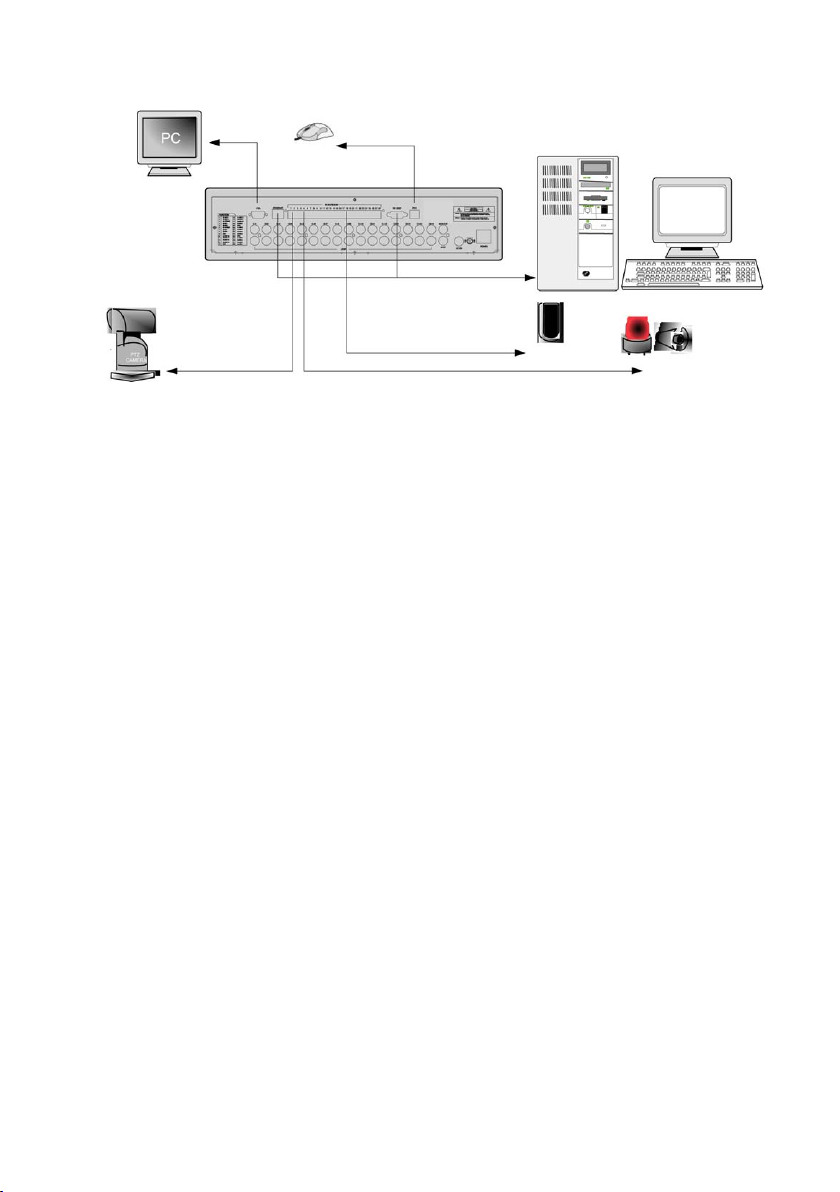
16 Channel
RS-232C: Control DVR through RS-232C port
RS-485: Control external device such as PTZ Cameras (Pin No.1 ~ 2 at Terminal Block)
RELAY Output: (Pin No.3 ~8 at Terminal Block)
SENSOR Input: (Pin No.10 ~ 13 / No. 15 ~ 18 / No. 20 ~ 23 / No. 25 ~ 28 at Terminal Block)
GND: Ground (Pin No. 9 / No. 14 / No. 19 / No. 24 at Terminal Block)
ETHERNET: Connection to LAN, WAN and Internet
VGA: Connection to VGA Monitor (CRT, TFT LCD Monitor)
User can change resolution in MONITOR SETUP / VGA SETUP / VGA RESOLUTION
15
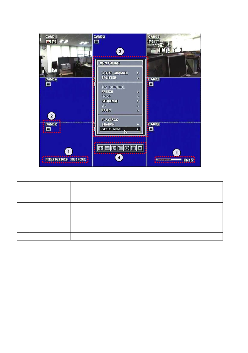
5. Display Configuration
1 Current Status
2 Display Status
3 Popup Menu
4 Toolbar
Display current Date/Time and Hard Disk allocation (Live view screen)
Display playback time, show percentage of Hard Disk allocation and speed of play
back (Play back screen)
Display status icons
Monitoring popup menu in live mode
Playback popup menu in playback mode
PTZ control popup menu in PTZ mode
Playback toolbar, PTZ toolbar
16
5.1 Current Status
5.1.1 Date/Time
Live mode: show current date & time
Playback mode: show recorded date & time of the playback image
5.1.2 HDD
Live mode: HDD recorded space is marked red on the percentage bar.
Available remaining days/time at current record mode is shown.
Playback mode: Shows percentage of playback.
5.1.3 Playback Mode
In Playback mode, F stands for Forward playback, B for Backward playback.
The numbers show playback speed. (Example.) F 16x, B 2x
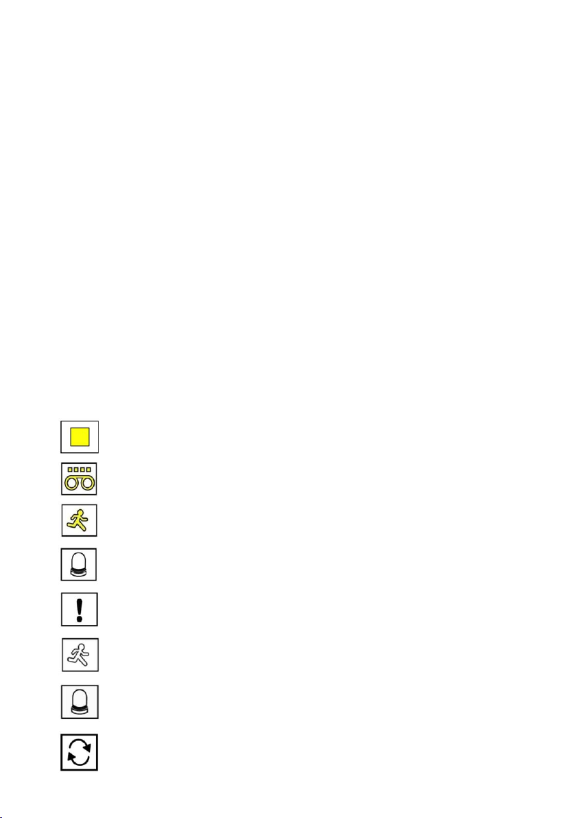
5.2 Display Status
Stop Recording, Not Recording
Continuous Recording in progress
Motion Recording in progress
Alarm Recording in progress
Panic Recording in progress
Motion detected
Alarm-In detected
HDD Overwrite
17
5.3 Popup Menu
There are three types of Popup Menu:
1. „MONITORING” popup menu
2. „PTZ CONTROL” popup menu
3. „PLAYBACK” popup menu
The Popup menus are provided for easy navigation and detail configuration. See each sectional explanation for
invoking popup menus.
5.3.1 MONITORING Popup Menu
The „MONITORING” popup menu is invoked by pressing „Menu” button located in front of the DVR, „Menu” button
located on the remote controller and right mouse button while in Live display.
In full screen mode: All sub-menus are activated.
In split screen mode: PTZ, Zoom, PIP menus are not activated.
In 16 split screen mode: Previous Page, Next Page, PTZ Control, Zoom, PIP are not activated.
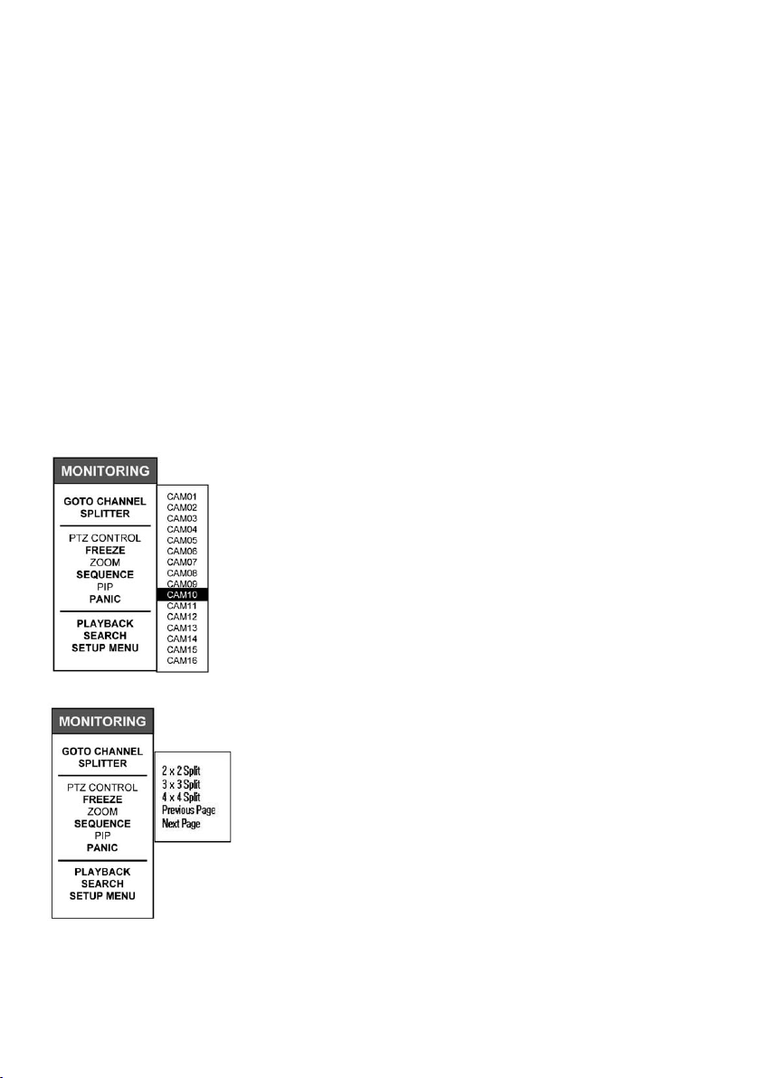
1) GOTO CHANNEL (Single channel camera selection)
Select „GOTO CHANNEL” from „MONITORING” popup menu.
Navigate by using directional button in frontal keypad and directional button on
remote controller or by using the mouse.
Off to the side another selectable list with camera labels will appear (Default
camera labels are CAM1~CAM16). Choose the desired camera by selecting
the label and single channel view of the camera selection will appear.
2) SPLITTER (2x2, 3x3, 4x4 Split, Previous page, Next Page)
Select „SPLITTER” from „MONITORING” popup menu.
Navigate by using directional button in frontal keypad and directional button
in remote controller or by using the mouse.
Select „2x2 Split” 4 split quad view, „3x3 Split” for 9 split view and „4x4 Split”
for 16 split view.
Full: [ 60(50) FPS @ 720 x 480 (720 x 576) ]
4 split: [ 240(200) FPS @ 360 x 240 (360 x 288) ]
9 split: [ 540(450) FPS @ 240 x 160 (240 x 192) ]
16 split: [ 960(800) FPS @ 180 x 120 (180 x 120) ]
For 4ch/8ch DVR, 3X3 and 4X4 split sub-menus will not be activated.
18

• Previous Page
By selecting „PREVIOUS PAGE” option in full screen mode, screen display view will switch screen to lower number
channel. (After channel 1, it rotates to channel 16.)
In split screen mode, clicking Previous Page menu will switch screen to lower number channel groups.
e.g. [ch1/2/3/4] –> [ch13/14/15/16] –> [ch9/10/11/12] –> [ch5/6/7/8]
In 16 split display mode, this function is not available.
• Next Page
By selecting „NEXT PAGE” option in full screen mode, screen display view will switch screen to higher number
channel. (After channel 16, it rotates to channel 1).
In split screen mode, clicking Next Page menu will switch screen to higher number channel groups.
e.g. [ch1/2/3/4]
In 16 split display mode, this function is not available.
3) PTZ CONTROL (invokes PTZ Control Toolbar and Virtual Joystick)
Select „PTZ CONTROL” from „MONITORING” popup menu.
NOTE: By pressing button marked „PTZ” on frontal key pad or remote controllers on single channel view will
invoke PTZ Control Toolbar and Virtual Joystick as well.
PTZ Control Toolbar and Virtual Joystick will display when PTZ Control menu is selected while in a single channel
view.
Frontal Key Pad and Remote Controller operation:
Locate sequence button marked „SEQ” and this button will shift keys in PTZ Control Toolbar and press button marked
„ ” (for Frontal key pad) or „OK” button (for Remote controllers)
Directional buttons will control the Virtual Joystick, however diagonal controls is not operable via the directional
button. (Recommend using Mouse for diagonal controls).
–> [ch5/6/7/8] –> [ch9/10/11/12] –> [ch13/14/15/16]
See Chapter 8.1 Live Monitoring, 5) PTZ mode for more details.
PTZ Control Toolbar
19
Virtual Joystick
4) FREEZE (On / Off)
Select „FREEZE” from „MONITORING” popup menu.
NOTE: By pressing button marked „FRZ” on frontal key pad or remote
controllers will freeze the screen and hitting it one more time will
release it.
Select „ON” that appears on expanded window from „FREEZE” selection to
freeze the frame and „Off” to release the screen freeze.
In Full screen mode, FRZ icon appears and screen freezes.
In split screen mode, FRZ icon appears and all channels freeze.
5) ZOOM: On / Off (Available only for live view)
Zoom option may be enable on live view by selecting single channel view then from the „Monitoring” popup menu
select „Zoom” then select „On” to enable Zoom.
Rectangular blue box located in right hand corner indicates zoomed area. (Zoomed fixed 2x)
You may select the zoom area either by directional key found on remote controller or frontal key pad. For the mouse
operation, you may left click on to the blue zoomed area and hold it and drag it to desired position.
To exit zoom mode, from the „Monitoring” popup menu select „Zoom” then select „Off” to disable Zoom.
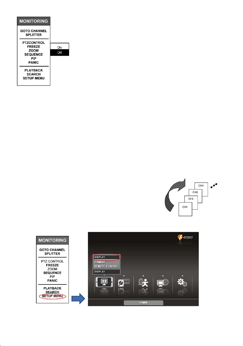
6) SEQUENCE: On / Off
To enable sequence mode, from „MONITORING” menu click on „SEQUENCE” then
select „ON” to enable sequence mode. (Clicking on „OFF” will disable sequence
mode.)
You may select sequence mode from single view or 4 split view from live display.
To configure sequence interval, from „Monitoring” popup menu select „Setup
Menu” you will see setup menu with five large icons.
Very first icon on the left is „Display” icon and within „Display” icon you will see „DISPLAY”, „CAMERA”, „AUDIO” and
„REMOTE CONTROL” list option items. Then select „Display”
20
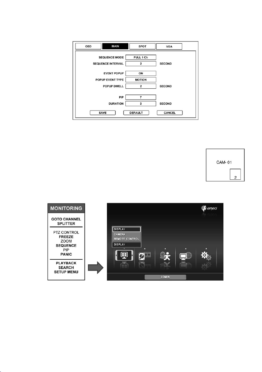
After selecting „DISPLAY” and a window will appear with „OSD”, „MAIN”, „SPOT” and „VGA” tabs.
Select „MAIN” tab and here you can configure sequence interval.
7) PIP: On / Off
Picture in Picture (PIP) mode will be enabled by selecting PIP button on the remote con
troller or in frontal keypad. With mouse operation, PIP will be enabled from „MONITORING”
popup menu then selecting „PIP”. From here you have an option to select „ON” or „OFF” to
enable and disable PIP.
To configure PIP, from „Monitoring” popup menu select „Setup Menu” you will see setup
menu with five large icons.
Very first icon on the left is „Display” icon and within „Display” icon you will see „DISPLAY”, „CAMERA”, „AUDIO” and
„REMOTE CONTROL” options. Then select „Display” list option item.
-
21
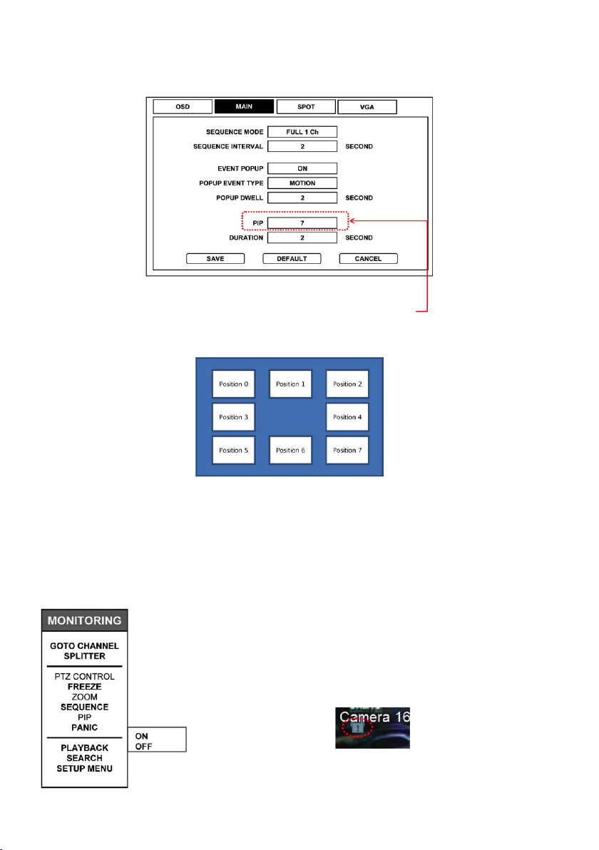
After selecting „DISPLAY” and a window will appear with „OSD”, „MAIN”, „SPOT” and „VGA” tabs. Select „MAIN” tab
and here you can configure PIP and DURATION.
PIP positioning option may be selected from „PIP” section in „MAIN” window.
There are 8 positions ranging from 0~7. See below for each position.
PIP Position location
8) Panic (Force recording)
Panic recording will be enabled by selecting „PANIC” from ‘MONITORING” popup.
Panic recording may be enabled from „MONITORING” popup menu then
selecting „PANIC”. Choosing „ON” will enable Panic record mode and „OFF”
will disable Panic record mode.
Panic mode indicator will be shown after Panic mode has been enabled.
It will appear on upper left corner of the screen as show on the picture below.
Example of panic Indicator
22
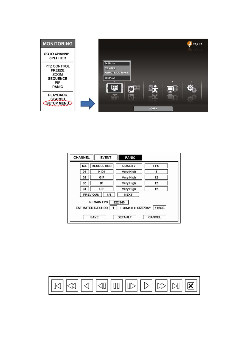
Image quality and frame rate of Panic record mode is configurable in „SETUP MENU” as shown below.
Choose second icon from the left and choose „SETUP”.
Upon selecting „SETUP” list option item from second icon in „SETUP MENU” a window will appear with three tabs
marked „CHANNEL”, „EVENT” and „PANIC”. Choose „PANIC” tab and you will be able to configure „RESOULTION”,
„QUALITY” and „FPS” (Frames per second) for every individual channels.
9) Playback
Press „PLAYBACK” from „MONITORING” popup menu or from search menu, and Playback Control Toolbar pops up
as below and begin playback of recorded data on HDD. Freeze, Slow/Fast (reverse) playback control is available with
Playback Control Toolbar.
Playback Control Toolbar
23

10) Search
The „SEARCH” option is accessible only by ADMIN and MANAGER accounts as default. Regular users may enter
search option if given authority by admin. (User authority explained further in Chapter 6.6, item 4).
In the „SEARCH” option you may enable „CALANDER SEARCH”, „EVENT SEARCH” and „BOOKMARK SEARCH”.
By clicking on „SEARCH” option from „MONITORING” popup it will immediately open the search option window as
illustrated below.
Detailed configuration of all the Search option will be explained in Chapter 7 of this manual.
11) Setup Menu
Only Admin and Manager have full authority to access and change all settings on all Sub-Menus.
(1) Setup Group indication: it indicates which icon selection is made.
(2) Option list: it list all possible options by Setup Group selection
(3) Setup Group icon: there are 5 setup group icons „DISPLAY”, „RECORD”, „EVENT”, „NETWORK” and „SYSTEMS”
(4) User Account indication: shows type of user account selected.
Detailed description of all setup menu items are explained in Chapter 5.1 of this manual.
24
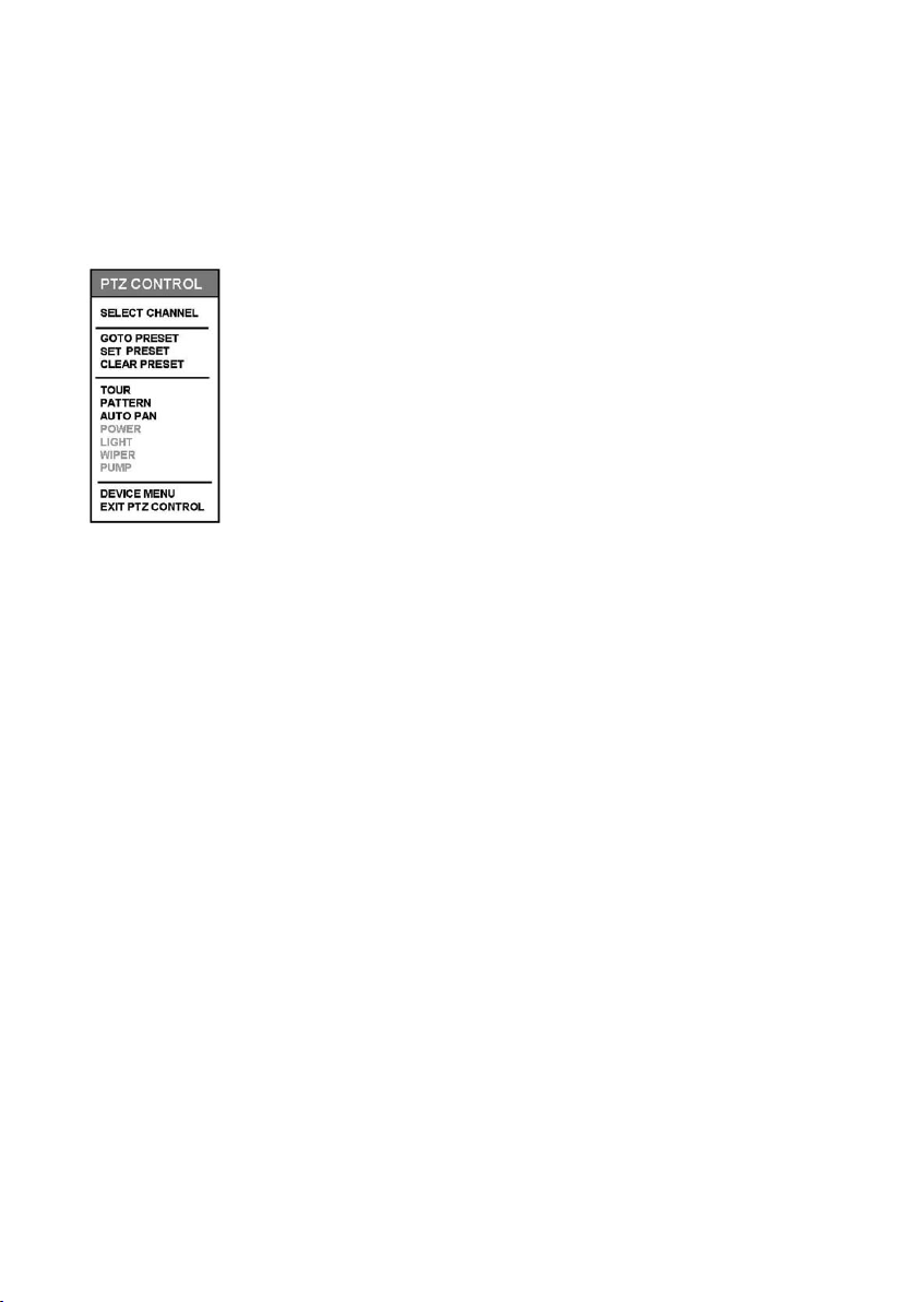
5.3.2 PTZ CONTROL Popup Menu
The „PTZ CONTROL” popup menu is available after invoking PTZ Control Toolbar and Virtual Joystick. (see page 19
item „3) PTZ CONTROL” )
Press „Menu” button on remote controller or frontal key pad. For the mouse operation right mouse button click to
invoke „PTZ CONTOL” popup menu
Upon clicking „SELECT CHANNEL” selectable list of all camera labels will appear.
Choose the camera label desired to move to the camera for PTZ control.
Upon clicking „GOTO PRESET” selectable list of camera preset labels will appear.
(default „POSITION 1”~ „POSITION 10”).
Select the preset position to view programmed preset position.
The „SET PRESET” option is used to configure preset as seen on the screen.
The „CLEAR PRESET” option is used to delete preset configured by „SET PRESET” option.
First identify preset you want to delete then use „GOTO PRESET” option to select proper
preset number. When PTZ is moved to the desired preset to delete then select „CLEAR
PRESET” to delete the preset.
1) Tour: Pan/Tilt on all directions
2) Pattern: Move designated PRESET position in order
3) Auto Pan: Pan left/right automatically
4) Power: On/Off
5) Light: Light on at night
6) Wiper: Wipe moisture or water drops
7) Pump: Pump water to remove dust
8) Device Menu: Show OSD Menu of PTZ camera
9) Exit PTZ Control: Exit and go back to Live view mode
NOTE: Detailed operation of „PTZ CONTROL” menu is illustrated on Chapter 7.1.5 PTZ.
Menus from
1) to 7) may not be available according to PTZ camera models.
25

5.3.3 PLAYBACK Popup Menu
While in Playback mode, press „Menu” button on remote controller or frontal key pad.
For the mouse operation right mouse button click to invoke „PLAYBACK” popup menu.
Upon clicking „GOTO CHANNEL” selectable list of all camera labels will appear.
Choose the camera label desired to move to the camera for PLAYBACK control.
Upon clicking „SPLITTER” selectable list that indicates following:
2x2 SPLIT
3x3 SPLIT
4x4 SPLIT
PREVIOUS PAGE
NEXT PAGE
NOTE: 2x2 SPLIT will enable playback view displaying 4 camera defaulting view of camera 1 ~ camera 4.
By selecting „PREVIOUS PAGE” it will show camera 13 ~ camera 16.
By selecting „NEXT PAGE” from camera 1 ~ camera 4 view, then it will show camera 5 ~ camera 8.
Clicking the „BOOKMARK” button while in playback mode, will index the time/date for Bookmark Search.
By clicking the „DE-INTERLACE” button while in playback mode. De-interlace is available via Interpolation.
By clicking the „SEARCH” button while in playback mode will stop playback mode, and go to search mode.
By clicking the „EXIT PLAYBACK” will enable the live view display.
26
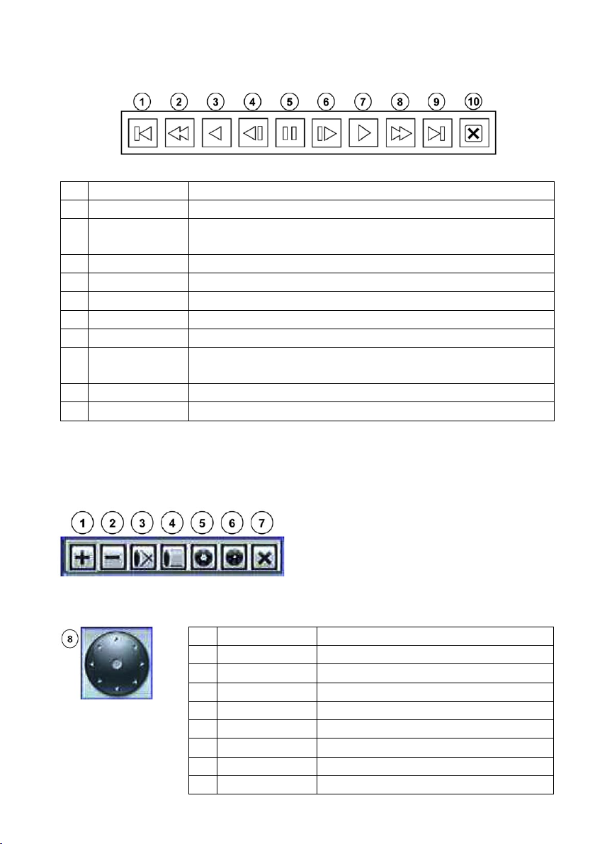
5.4 Toolbar
5.4.1 PLAYBACK Toolbar
No. Button Function
1
Go to the first image Move to the beginning of playback
2
Decrease speed Playback speed decreases in forward playback
(Playback speed increases in backward playback)
3
Backward playback Playback in reverse direction
4
Previous image Shows previous image in single still picture
5
Freeze Freeze playback
6
Next image Shows next image in single still picture
7
Forward Playback Playback in forward direction
8
Increase speed Playback speed increases in forward playback
(Playback speed decreases in backward playback)
9
Go to the last image Move to the end of playback
10
Exit Exit playback mode, and return to live mode
5.4.2 PTZ Toolbar
PTZ Control Toolbar
Virtual Joystick
No. Button Function
1
TELE Zoom in
2
WIDE Zoom out
3
NEAR Focus near
4
FAR Focus far
5
OPEN Iris open
6
CLOSE Iris close
7
EXIT Exit PTZ toolbar
8
JOYSTICK Camera Pan/Tilt operation
27
6. DVR Setup
6.1 Operation
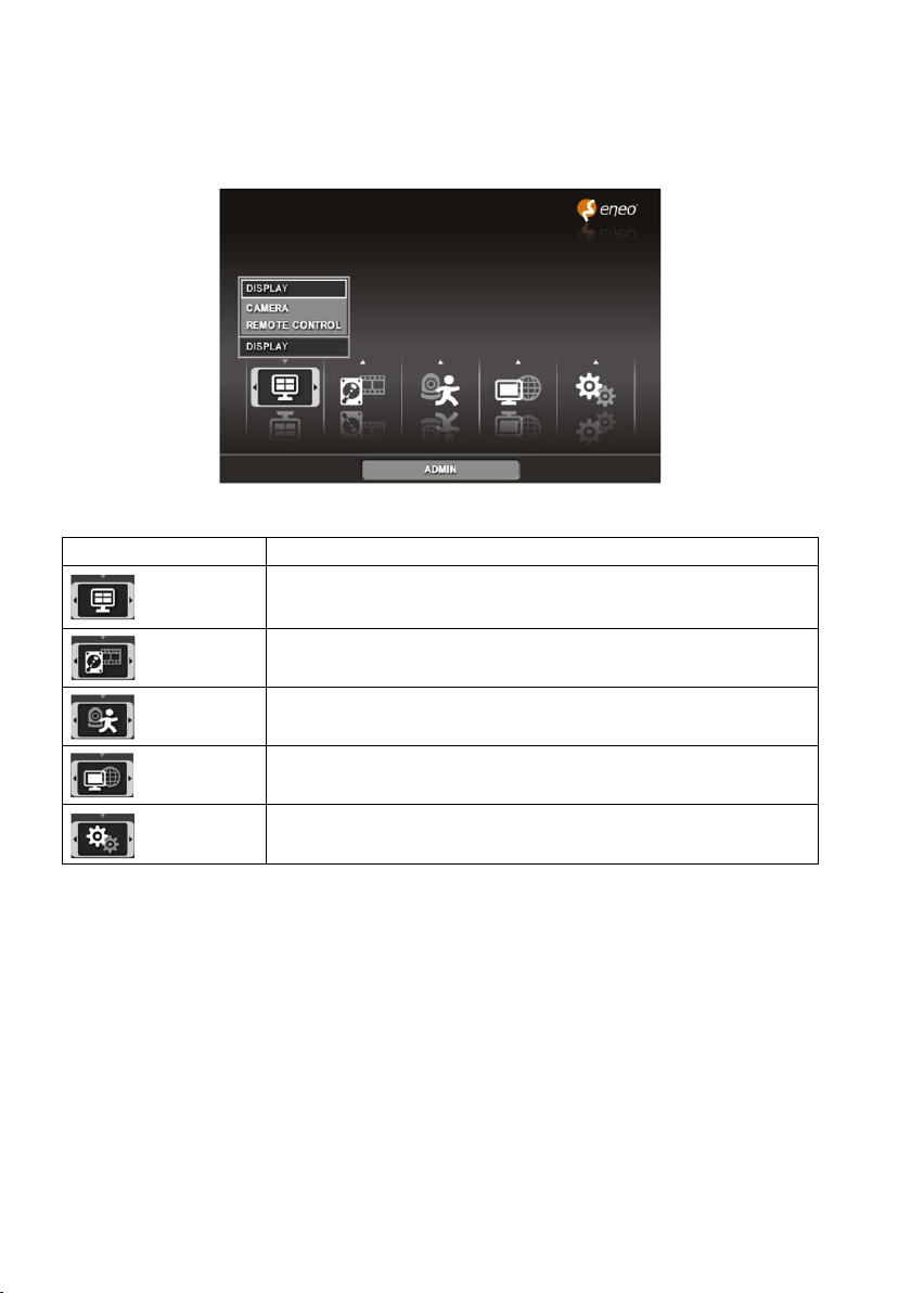
6.1.1 Main Menu
Setup Group Icon Available List Option items
Display
Record
Event
Network
System
DISPLAY, CAMERA, REMOTE CONTROL
SETUP, SCHEDULE, BACKUP
ALARM, MOTION, VIDEO LOSS, ALARM-OUT, BUZZER
LAN, NOTIFICATION
INFORMATION, DATE/TIME, STORAGE, USER, LOGOUT
28
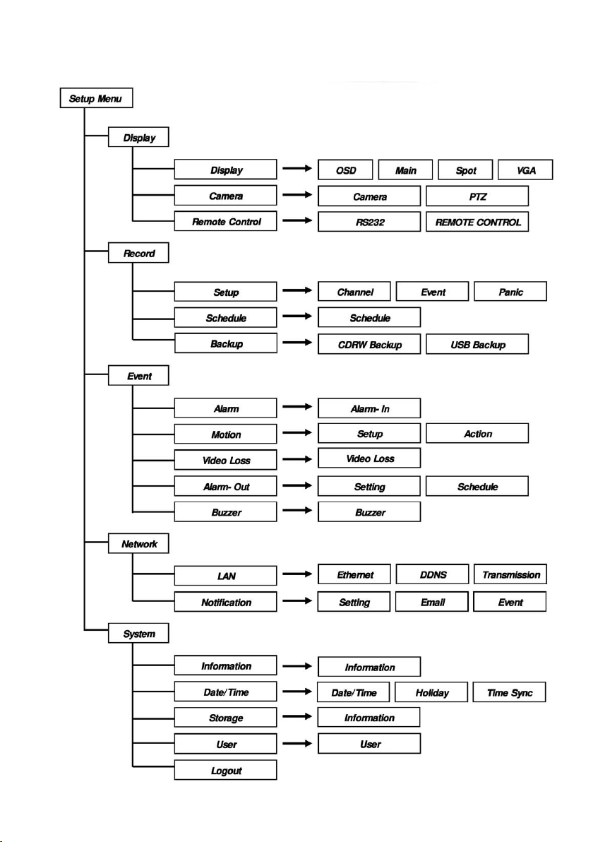
6.1.2 Map of Screens
29
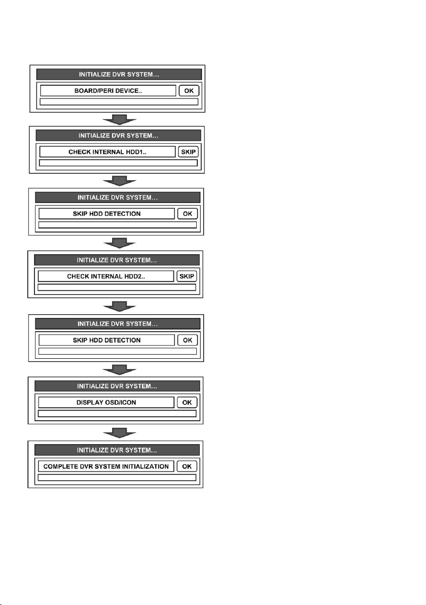
6.1.3 Initialization
When powered on, messages displays
in order.
System will check for connected HDDs.
If no HDD is connected, it will move to
the next message. To skip checking HDD,
click SKIP button or press
MENU button.
Once initialization is completed, live
screen displays.
30
 Loading...