

Eneo AK-5 Callisto dome series Installation Manual
Installation Guide
Camera junction box for
Callisto dome series
AK-5
DE
EN
FR
PL
RU

22
Inhalt
Inhalt ..........................................................................................................................................2
Sicherheitshinweise ................................................................................................................3
Lieferumfang ............................................................................................................................3
Produktbeschreibung und Anschlüsse ...............................................................................3
Installation ................................................................................................................................4
Anschlüsse ...............................................................................................................................5
Verkabelung durch seitliche Kabelverschraubung .................................................5
Verkabelung durch Kabeltüllen im Boden ..............................................................5
Verwendung des Steckverbinders .........................................................................6
Verkabelungsanleitung ...........................................................................................................6
Kabelorganisation für Analog / HDcctv Kameras ...................................................6
Kabelorganisation für IP Kameras .........................................................................7
Signalbelegung ......................................................................................................7
Weitere Informationen ............................................................................................................8
3
DE
EN
FR
PL
RU
3
DE
EN
FR
PL
RU
Produktbeschreibung und Anschlüsse
Lieferumfang
Sicherheitshinweise
Bitte beachten Sie auch die beiliegenden Sicherheitshinweise und lesen Sie diese
Anleitung vor Inbetriebnahme sorgfältig durch.
Wichtige Hinweise sind mit einem Achtungsymbol gekennzeichnet.
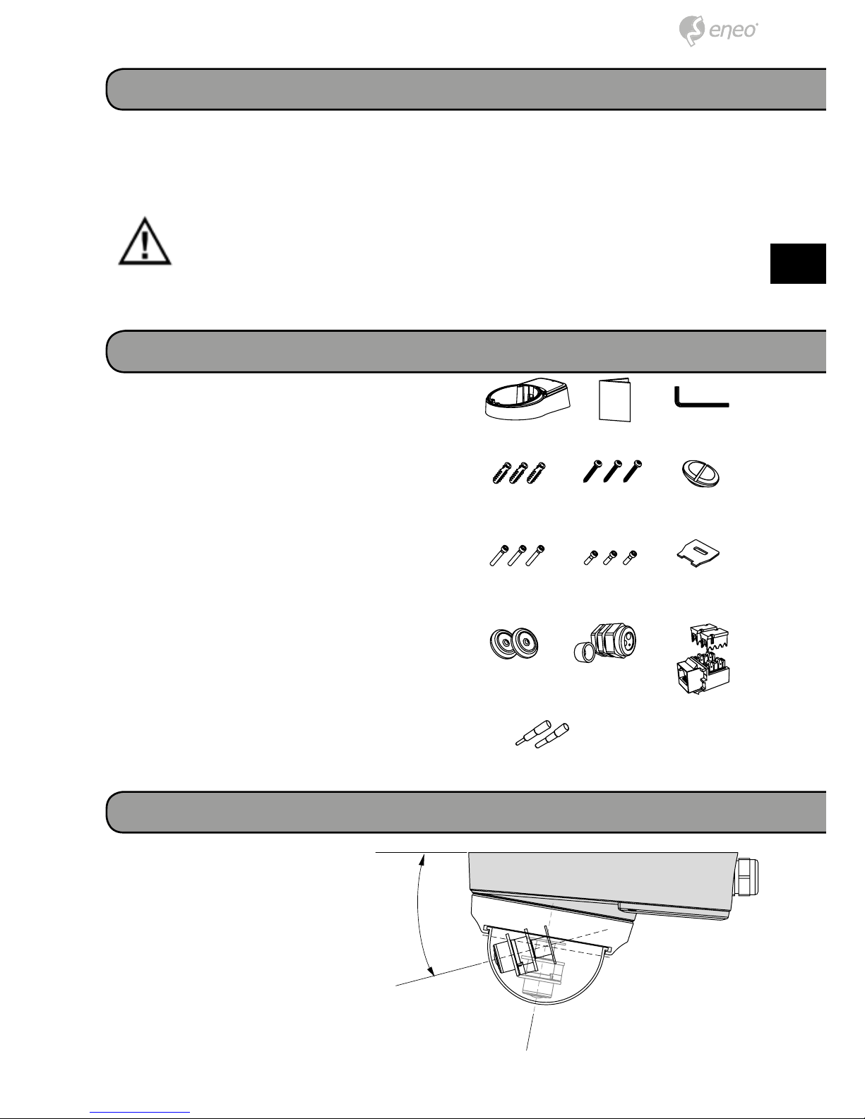
• 1x Anschlussbox
• 1x Installations- und Betriebsanleitung
• 1x Inbusschlüssel
• 3x Kunststoffdübel 6x30mm
• 3x Montageschraube 4x40mm
• 1x Blindstopfen
• 3x Verbindungsschraube 4x30mm
• 3x Verbindungsschraube 4x14mm
• 1x Blindstopfenschlüssel
• 2x Kabeltülle
• 1x Kabelverschraubung & Adapterring
• 2x Stopfen für Kabelverschraubung (1x
∅4.5mm, 1x ∅2,7mm)
• 1x Steckverbinder (CAT.5e)
Die Anschlussbox an einer tragfähigen Struktur wie z.B. einer
Betonwand oder einer Decke
befestigen. Dieses Produkt erweitert die Begrenzung des Betrachtungswinkels der Kamera und
schafft Platz für die Organisation
der Anschlusskabel.
15º
44
Technische Daten
Material:
Oberfläche:
Umgebung:
Gewicht:
Schutzart:
Aluminum Druckguss
Hellgrau spritzlackiert
Innen-/Außenbereich für Callisto Dome
1,3kg
IP66
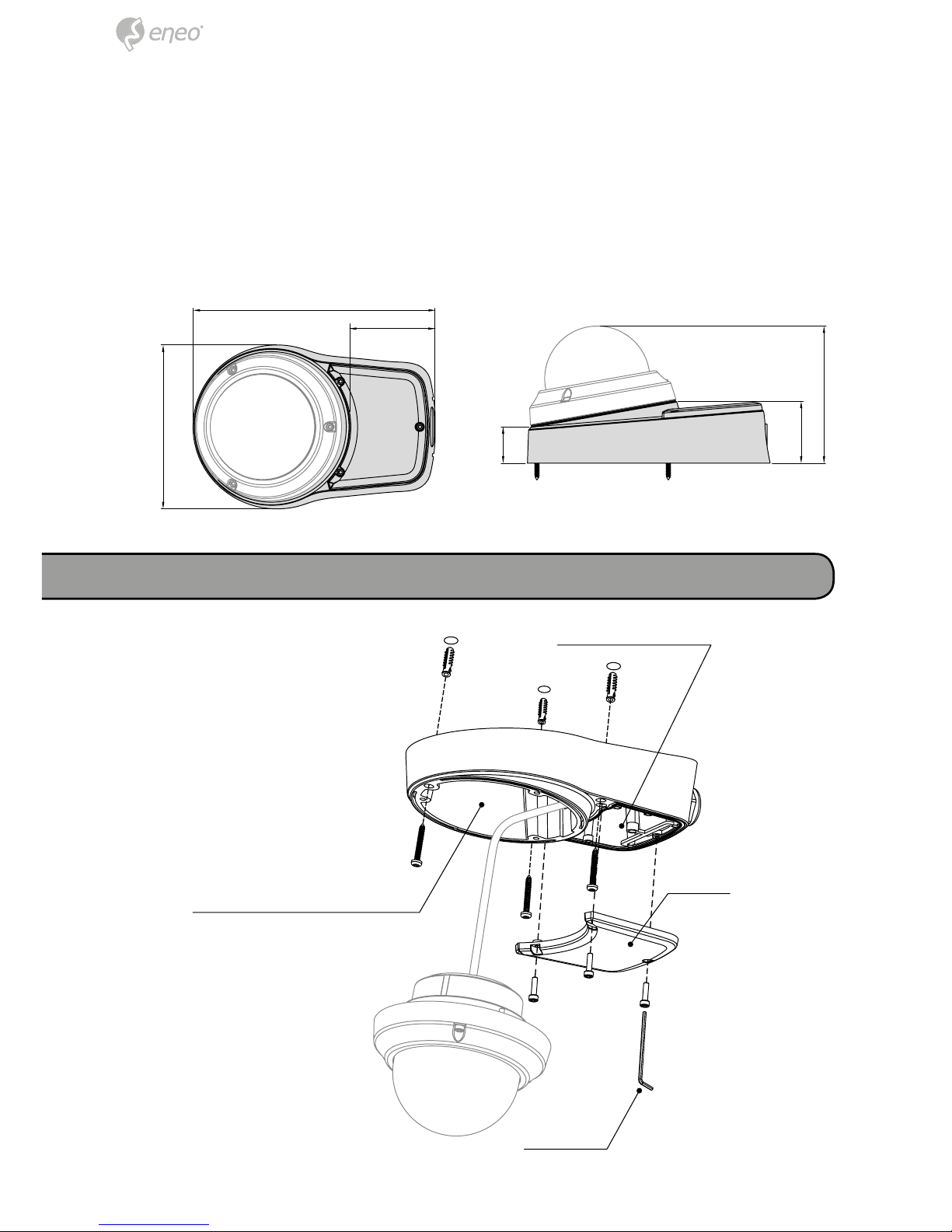
Installation
Keiladapter
Anschlussbox
Abdeckung
Inbusschlüssel
229.85
82
155.3
58.7
34.6
130
5
DE
EN
FR
PL
RU
5
DE
EN
FR
PL
RU
Anschlüsse
1. Halten Sie die Bohrschablone an die Installationsstelle und bohren Sie die Löcher in Decke oder Wand, falls erforderlich.
2. Setzen Sie die Anschlussbox an die Stelle mit den vorgebohrten Löchern und
befestigen Sie sie mit den Montageschrauben durch die Montagelöcher (3x).
3. Verlegen Sie das Dome Kabel in die Anschlussbox und befestigen Sie den
Dome wie dargestellt mit den Verbindungsschrauben am Keiladapter.
4. Verbinden Sie das Dome Kabel mit der Spannungsversorgung und organisieren
Sie dann die verbundenen Kabel.
5. Setzen Sie die Abdeckung auf die Anschlussbox und ziehen Sie die Verbindungsschrauben fest.
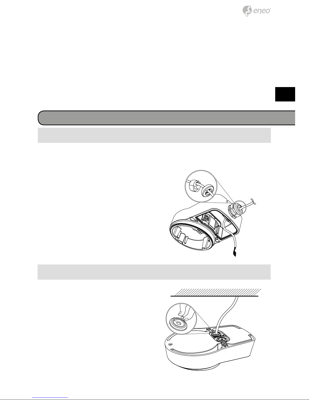
1. Schrauben Sie die Kappe der Kabelverschraubung ab und legen Sie
das Kabel aus der Wand oder der
Decke durch. Verschließen Sie die
anderen Öffnungen der Kabelverschraubung mit den beiliegenden
Stopfen. Führen Sie die Kabel mit
der Kabelverschraubung durch die
Seite der Anschlussbox wie dargestellt.
2. Zum Anschließen des Spannungsversorgungskabels an die Domekabel beachten Sie den Abschnitt
Signalbelegung.
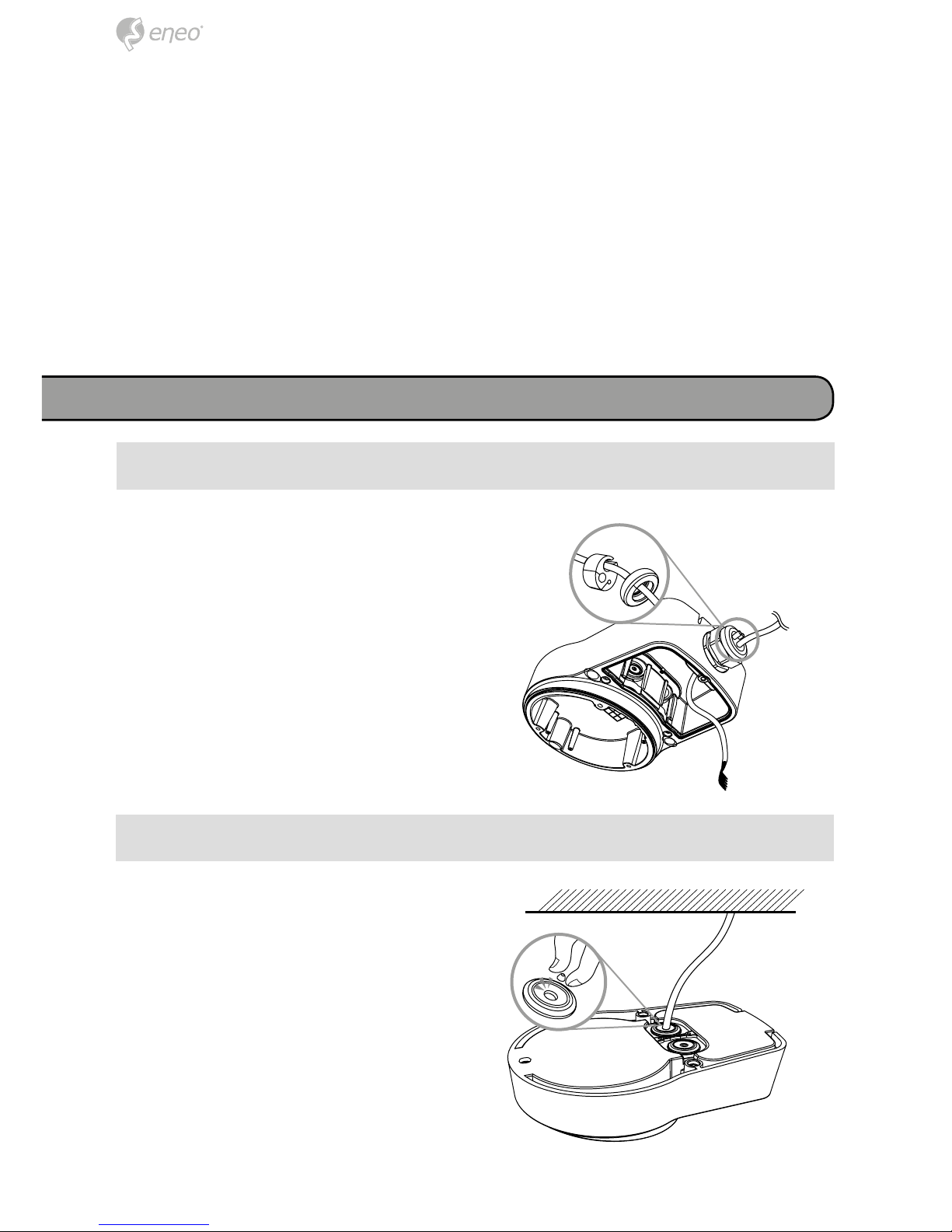
Verkabelung durch seitliche Kabelverschraubung
Verkabelung durch Kabeltüllen im Boden
1. Entfernen Sie die Spitzen der Kabeltüllen und legen Sie die Kabel
aus der Decke oder der Wand
durch. Führen Sie die Kabel mit den
Kabeltüllen durch den Boden der
Anschlussbox wie dargestellt.
2. Zum Anschließen des Spannungsversorgungskabels an die Domekabel beachten Sie den Abschnitt
Signalbelegung.
66
Verkabelungsanleitung
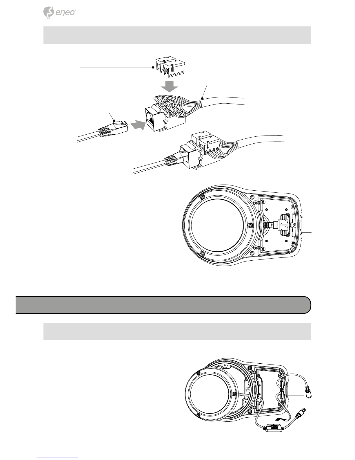
1. Richten Sie die Kabeldrähte am
Steckverbinder aus. Dann drücken
Sie die Steckverbinderabdeckung
wie dargestellt fest.
2. Organisieren Sie die verbundenen
Kabel in der Anschlussbox.
Verwendung des Steckverbinders
① Das Kabel an der Domebasis ist
gelöst.
② Verbinden Sie die Spannungsversorgungskabel mit den jeweiligen Anschlüssen.
* Beachten Sie den Abschnitt Signalbelegung beim Verbinden der Kabel.
Kabelorganisation für Analog / HDcctv Kameras
Steckverbinderabdeckung
Ethernet
Kabel
Spannungsversorgungskabel
7
DE
EN
FR
PL
RU
7
DE
EN
FR
PL
RU
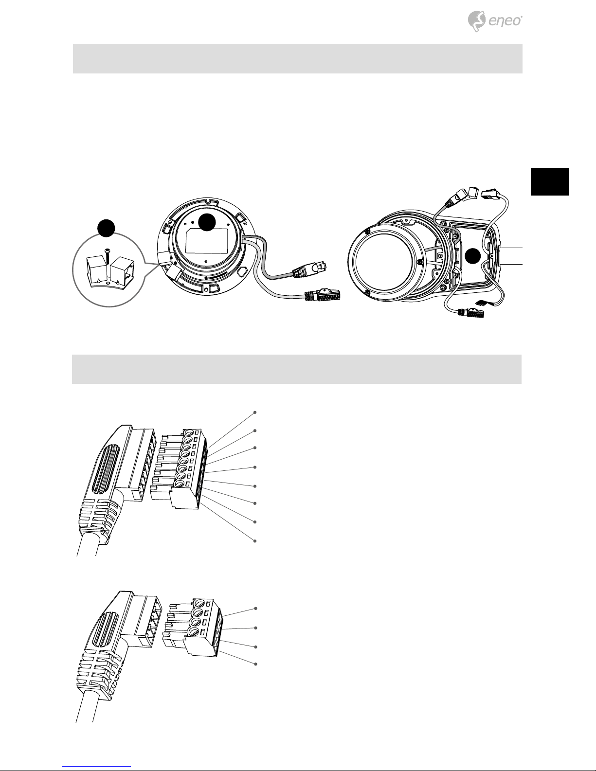
Kabelorganisation für IP Kameras
① Die Kabel an der Domebasis sind gelöst.
② Demontieren Sie die Kopplerplatine für die LAN Verkabelung.
③ Verbinden Sie die Ethernet- und Spannungsversorgungskabel mit den jeweiligen
Anschlüssen.
Signalbelegung
~24V / 12VDC
~24V / GND
Alarm-Ein
Alarm-Aus
GND
Audio-In
Audio-Out
GND
~24V / 12VDC
~24V / GND
RS485 (RTX+)
RS485 (RTX-)
1
2
3

88
Weitere Sprachversionen dieser Anleitung sind auf der eneo Website unter
www.eneo-security.com verfügbar.
Weitere Informationen

9
DE
EN
FR
PL
RU
Contents
Contents ...................................................................................................................................9
Notes on safety .................................................................................................................... 10
Scope of delivery ................................................................................................................. 10
Product description and connections .............................................................................. 10
Installation ............................................................................................................................. 11
Cable connections ............................................................................................................... 12
Cable through with the gland on the side ............................................................12
Cable through with the grommets on the bottom .................................................12
Using the modular jack connection ......................................................................13
Cabling instruction ............................................................................................................... 13
Cable assembling for Analog / HDcctv cameras ................................................13
Cable assembling for IP cameras .......................................................................14
Signal assignment .............................................................................................14
Further information ............................................................................................................. 15
10
Product description and connections
Scope of delivery
Notes on safety
Please also pay attention to the enclosed safety instructions, and carefully read
through this instruction guide before initial operation.
Important points of advice are marked with a caution symbol.
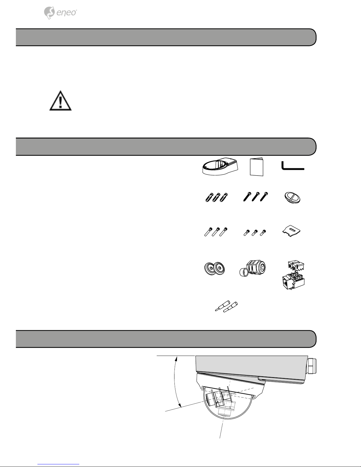
• 1x Mount adaptor
• 1x Installation and Operating Instructions
• 1x L-wrench
• 3x Plastic anchor 6x30mm
• 3x Mounting screw 4x40mm
• 1x Pipe hole cap
• 3x Assembly screw 4x30mm
• 3x Assembly screw 4x14mm
• 1x Pipe cap driver
• 2x Cable grommet
• 1x Cable gland & adaptor ring
• 2x Gland hole plug (1x ∅4.5mm, 1x
∅2.7mm)
• 1x Modular jack (CAT.5e)
Install the mount onto a strong
structure such as a concrete wall
or ceiling. This product is used
to extend the camera‘s viewing
angle limit and to make space
for the organization of the cable
connection.
15º
11
DE
EN
FR
PL
RU
Technical specifications
Construction:
Finish:
Environment:
Weight:
Protection:
Aluminum die-casting
Light-gray spray
Indoor/Outdoor for a Callisto dome
1.3kg
IP66
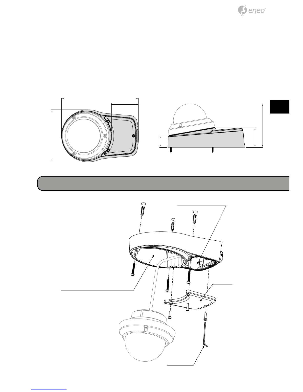
Installation
Tilted surface mount
part
Junction box part
Cover
L-Wrench
229.85
82
155.3
58.7
34.6
130
12
Cable connections
1. Locate the mounting template at the installation position and drill the ceiling or
wall if needed.
2. Place junction box part on pre-drilled position and fix it through mount holes
(x3) by using mount screws.
3. Route the dome cable to the junction part and attach the dome to the surface
mount part using assembly screws as shown.
4. Connect the dome cable with the power source then organize the connected
cables.
5. Put the junction part cover to the unit and tighten the assembly screws.
1. Untwisted the gland cap and route
the cables from the ceiling or wall.
Then plug up the other holes of
gland using the gland hole plugs
supported. Put the cables with
gland onto the side of the tilted
junction mount as illustrated.
2. Refer to the signal assignment when
the power source cable connect
with the dome cables.
Cable through with the gland on the side
Cable through with the grommets on the bottom
1. Tear off the cocks of grommets and
route the cables from the ceiling or
wall. Then put the cables with grommets onto the bottom of the tilted
junction mount as illustrated.
2. Refer to the signal assignment when
the power source cable connect
with the dome cables.
 Loading...