

ENENSYS Divi Catch RF User Manual
DiviCatch RF
Live RF and ASI to
USB2.0 pocket adapter
and stream analyzer
USER GU I D E
ENENSYS Technologies
Le Germanium
80 avenue des Buttes de Coesmes
35700 Rennes
FRANCE
Office (+33) 2 99 12 79 06
Fax (+33) 2 99 12 79 05
www.enensys.com
contact@enensys.com
DVB is a Trade Mark of the DVB Digital Video Broadcasting Project (1991 to 1996) – DVB Product ID: 4937/4938
2007 11 - Subject to change without notice – Rev 4.3
Baseband Converters ¨
Network Adapters þ

Table of Contents
INTRODUCTION........................................................................................................................... 3
Product Overview..................................................................................................................... 3
Related Documents................................................................................................................... 3
PC/Laptop minimum requirements.............................................................................................. 4
INSTALLATION............................................................................................................................. 5
Software installation............................................................................................................... 5
Plug DiviCatch for the first time (Windows XP or Windows 2000 only)............................................ 5
Very interesting remarks......................................................................................................... 5
RUNNING DIVICATCH SOFTWARE
FOR THE FIRST TIME.................................................................................................................... 6
DiviCatch RF – General panel..................................................................................................... 6
DiviCatch RF-C – Signal tuning................................................................................................... 7
DiviCatch RF-T/H – Signal tuning................................................................................................ 7
DiviCatch RF - Monitor & log panel.............................................................................................. 8
DiviCatch RF - DVB-H Analysis.................................................................................................. 19
Burst structure........................................................................................................................ 20
FER and MFER......................................................................................................................... 20
Delta_T information................................................................................................................. 21
RF Analysis............................................................................................................................. 22
DiviCatch RF-C........................................................................................................................ 22
DiviCatch RF-T/H..................................................................................................................... 25
DiviCatch – Record & video panel.............................................................................................. 27
DiviCatch RF-T/H – ESG panel................................................................................................. 31
Configurable profiles............................................................................................................... 32
DiviCatch RF – GPS option....................................................................................................... 32
External cartographic applications.............................................................................................. 34
DiviCatch application and device status..................................................................................... 36
Notes and remarks................................................................................................................. 36
REGULATORY & STATUTORY NOTICES........................................................................................... 37
EMC and safety declaration...................................................................................................... 37
Environmental specifications.................................................................................................... 37
TECHNICAL DATA....................................................................................................................... 38
Interfaces Specifications.......................................................................................................... 38
ANNEX...................................................................................................................................... 39
Installation of VideoLan........................................................................................................... 39
ENENSYS DiviCatch RF - Manual Page 2 / 40
DiviCatch RF
User Guide

I N T R O D U C T I O N
P r o d u c t O v e r v i ew
DiviCatch RF refers to all RF-enabled DiviCatch devices. This manual covers
DiviCatch RF-C and DiviCatch RF-T/H devices.
ENENSYS' DiviCatch RF was designed to catch a live modulated signal or an
MPEG2 Transport Stream from any application and turn it into a USB2.0 link to be
received by a laptop equipped. DiviCatch RF is equipped with an RF tuner and a
demodulator for signal analysis. DiviCatch RF also integrates an ASI input to allow
for MPEG2 TS monitoring and analysis.
When connected to an MPEG2 source, DiviCatch is able to record it on the hard
drive of a PC (provided that source is valid), and also to monitor displayed services.
DiviCatch is self-powered. It gets its power from USB bus, thus does not require
any external power supply.
R e l a t e d D o c u m e n ts
[1] ETSI EN 300 468 “Digital Video Broadcasting (DVB); Specification for Service Information (SI)
in DVB systems.” (DVB-SI)
[2] EN 50083-9 Interfaces for CATV/SMATV Headends and similar Professional Equipment
[3] ETSI EN 300 429 Digital broadcasting systems for television, sound and data services;
Framing structure, channel coding and modulation for cable systems
[4] TR 101 891 Digital Video Broadcasting (DVB); Professional Interfaces: Guidelines for the
implementation and usage of the DVB Asynchronous Serial Interface (ASI).
[5] USB Specification Universal Serial Bus Specification Revision 2.0 (April 27, 2000)
[6] ATSC A65 PROGRAM AND SYSTEM INFORMATION PROTOCOL FOR TERRESTRIAL
BROADCAST AND CABLE
[7] ITU-T J83 Digital multi-programme systems for television, sound, data and services for
cable distribution
[8] ETSI EN 300 744 Digital Video Broadcasting (DVB); Framing structure, channel coding and
modulation for digital terrestrial television
[9] ETSI EN 302 304 Digital Video Broadcasting (DVB); Transmission System for Handheld
Terminals (DVB-H)
[10] ETSI TR 101 290 Digital Video Broadcasting (DVB); Measurement guidelines for DVB systems
ENENSYS DiviCatch RF - Manual Page 3 / 40
DiviCatch RF
User Guide

P C / L a p t o p m i n i m u m r e q u i r e m e n ts
Any PC equipped with USB2.0 interface and an application running on Windows
OS (Windows 2000 or Windows XP), at least PIII @ 300MHz supported by 256 MB
RAM.
Depending on bit rates to process and analyze, higher configurations may be
required, especially with DiviCatch RF devices. The more analysis modules are
started, the more memory and CPU are used: Always check CPU and memory
usage. Recommended configuration for all types of streams is CPU @ 1.66GHz and
0,99GB RAM.
Depending on bit rates to record, hard drive speed is a determinant factor. For
input bit rates lower than 80Mbps, a 5400 RPM disk is enough. For higher
throughputs, it is recommended to mount a faster disk (7200 RPM or above, with
eventually Serial ATA or SCSI interface).
DirectX 9.0 (or higher) library is required so that audio/video services can be
displayed in the Analysis window. DirectX 9.0 is provided with Windows XP. It can
also be downloaded and installed from Windows' website.
ENENSYS DiviCatch RF - Manual Page 4 / 40
DiviCatch RF
User Guide

I N S T A L L A T I O N
S o f t w a r e i n s t a lla t i o n
Install DiviCatch software from Companion CD. Execute the setup file from the folder ENENSYS
Software\DiviCatch\GUI and follow instructions.
NOTE: It is important that no DiviSeries device is attached to the computer during the installation.
P l u g D i v i C a t c h f o r t h e f i r s t t im e (Windows XP or Windows 2000 only)
– Once the installation process has completed, connect the DiviCatch RF device to a USB2.0 port on the
computer using the USB cable shipped with the DiviCatch RF device.
– Windows system finds new hardware and launches a new hardware wizard automatic driver installation
wizard. Choose “No, not this time”, and click Next. Then choose “Install the software automatically”, and
click Next. Continue until installation is complete.
– Wait for a couple of seconds (no need to unplug/replug); Windows system will re-enumerate the
device and will ask for a second driver installation. Same as previous step and continue until
install is complete.
– When driver installation is done, DiviCatch RF led gets red. Then launch the application
(DiviCatch RF led gets orange).
V e r y i n t e r e s t i n g r e m a r k s . . .
• Driver installation is only valid for the very USB2.0 port the DiviCatch RF device is connected to. If
DiviCatch RF is connected to any other USB2.0 port, Windows system will start another device
enumeration and behave as if a new USB device was detected. Companion CD will not be required and
Windows re-enumeration wizard will self complete. In order to be able to use the DiviCatch RF device
from any USB2.0 port, installation must be done for each USB2.0 port.
• DiviCatch application is not workable when no DiviCatch device is connected to the USB2.0 port of the PC.
• If you have purchased the GPS option, check the “GPS drivers” box at installation time without the GPS
receiver being connected to the PC.
•Meaning of LED colors on device:
OFF: no driver installed, happens when DiviCatch RF is plugged for the 1st time.
Red: Driver installed and device is recognized
Orange: DiviCatch application is launched (SW and device are connected), DiviCatch is ready to run
Green: receiving a stream (slow blink=188, fast blink=204 bytes/packet TS)
ENENSYS DiviCatch RF - Manual Page 5 / 40
DiviCatch RF
User Guide

R U N N I N G D I V I C A T C H S O F T W A R E
F O R T H E F I R S T T I M E
D i v i C a t c h R F – Gener a l p a n e l
This panel gives information about the device attached to the PC via the USB2.0
link in order to:
• Check graphically if receiving one stream (arrow blinks green meaning
that the device is synchronized and receiving TS packets),
• Get general information such as DiviCatch RF Serial Number and FW/SW
versions,
• Check through a single click if a new software release is available for
your product (requires an Internet connection to access Enensys' web
site).
Sample General Panel for DiviCatch RF-C
ENENSYS DiviCatch RF - Manual Page 6 / 40
DiviCatch RF
User Guide
Blinks green when
receiving stream
packets (ASI input)
General
information
Blinks green when
locked to a modulated
signal (RF input)
Check if new release is
available (requires
Internet connection)
RF and ASI inputs
All DiviCatch RF feature both an ASI input and an RF input. Either can be used
to receive a stream (live for RF and baseband for ASI) and analyze or process it.
Switching between RF and ASI inputs is operated through the general panel by
graphically selecting the input to be used (click on the arrow).
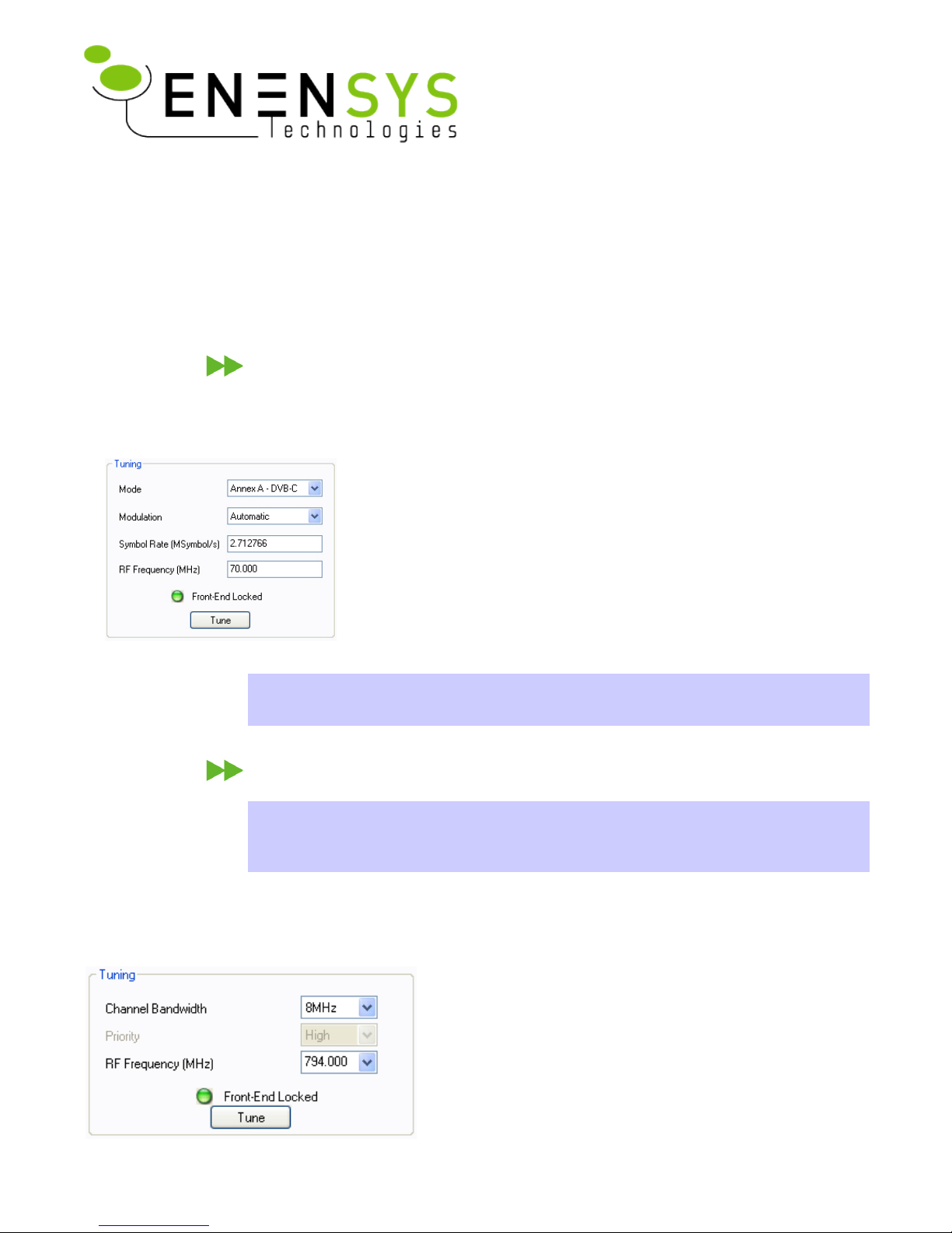
D i v i C a t c h R F - C – S i g n a l t u n i n g
The DiviCatch RF-C must lock the cable input signal. The Tuning section in the
RF Cable panel lets you specify all the necessary information to tune the device to
the desired signal.
● Mode: specify the Annex used (A, B or C) to modulate the signal
● Modulation: specify the type of modulation applied to the signal
(default value: automatic for auto-detection)
● Symbol rate: specify the symbol rate (expresses in Msymbols/s)
● RF Frequency: specify the frequency on which the signal is
received (expressed in MHz)
Then, click the “Tune” button. If the device is tuned to a signal,
the Tuning led turns green and the message Front-End locked is
displayed. On the DiviCatch RF-C device, the led also turns to blinking green.
Note: All frequencies entered are kept in history for quicker reuse. This information
is saved into the profile, allowing you to have your own frequencies on different
stations.
D i v i C a t c h R F - T / H – S i g n a l t u n i n g
Note: The portable antenna provided with the product is intended as a “starter”
antenna. Depending on environmental conditions and network topology, this
antenna may not be powerful enough to tune to all signals. If this is the case, it is
recommended that a more powerful antenna (offering gain) is used.
The DiviCatch RF-T/H must lock the DVB-T or DVB-H input signal. The Tuning
section in the RF-T/H panel lets you specify all the necessary information to tune
the device to the desired signal.
● Channel bandwidth: Specify the channel bandwidth
occupied by the multiplex you would like to connect
to. Choose between 5, 6, 7 or 8 (expressed in MHz).
● RF Frequency: Specify the frequency on which the
signal is received (expressed in MHz).
Then, click the “Tune” button. If the device is tuned to
a signal, the Tuning led turns green and the message
Front-End locked is displayed. On the DiviCatch RF-
T/H device, the led also turns to blinking green.
ENENSYS DiviCatch RF - Manual Page 7 / 40
DiviCatch RF
User Guide
● Priority: If hierarchical modulation is used on the channel to which the
DiviCatch RF-T/H is locked, this drop-down list is used to specify which
priority should be monitored.
Note: All frequencies entered are kept in history for quicker reuse. This information
is saved into the profile, allowing you to have your own frequencies on different
stations.
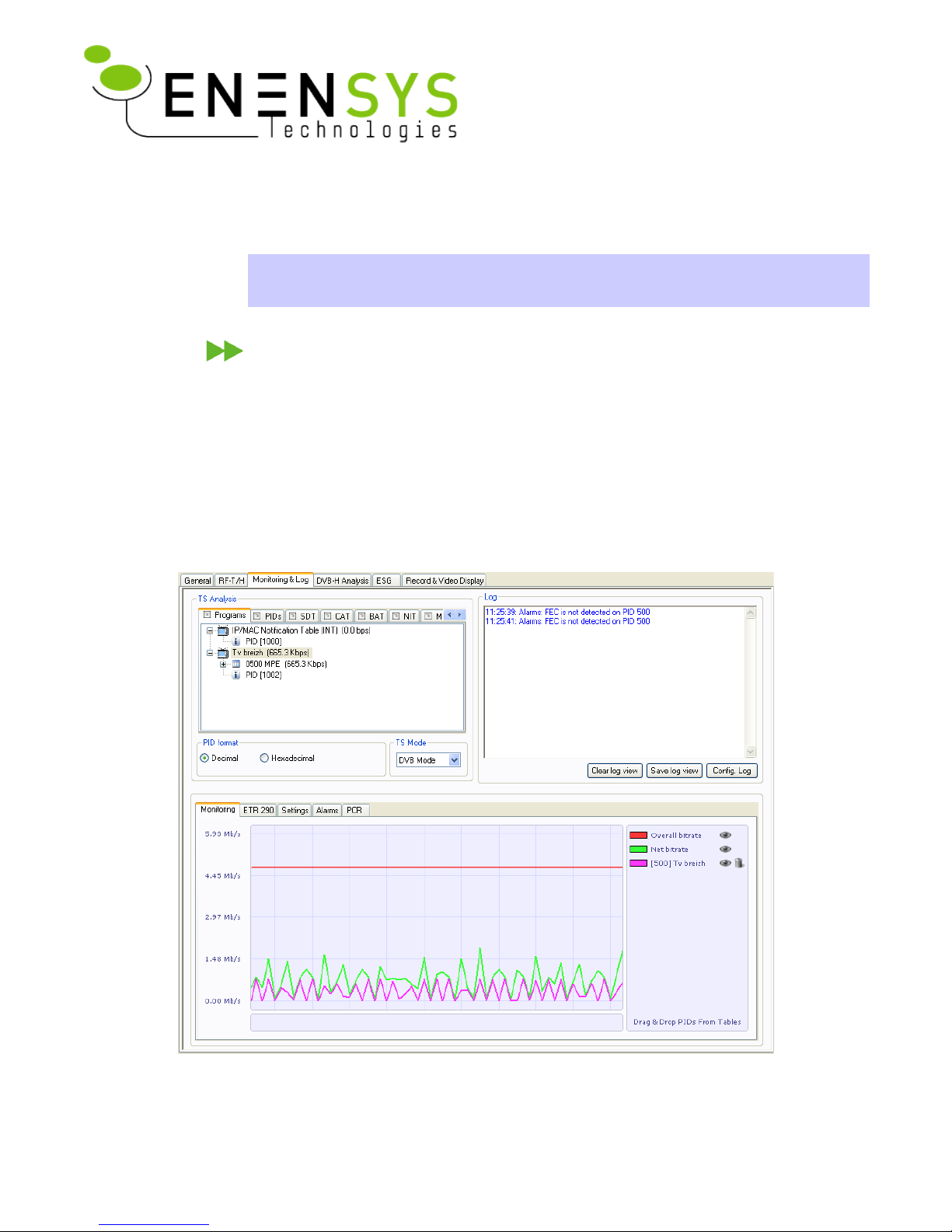
D i v i C a t c h R F - Mon i t o r & l o g p a n e l
• Real time TS Analysis, providing PSI/PSIP/SI table parsing
• Log, providing error or information messages on device or stream.
• Monitoring, providing 4 types of information:
• Real-time graph of bitrate information,
• ETR290 error measurement,
Note: Both monitoring features can be configured through the Settings tab.
• Pre-defined alarms on MPEG2-TS and DVB-H layer,
• PCR Jitter (Accuracy) graph.
Real time TS analysis
In the TS Analysis section, information is provided on Programs, PIDs and specific table parsing.
ENENSYS DiviCatch RF - Manual Page 8 / 40
DiviCatch RF
User Guide
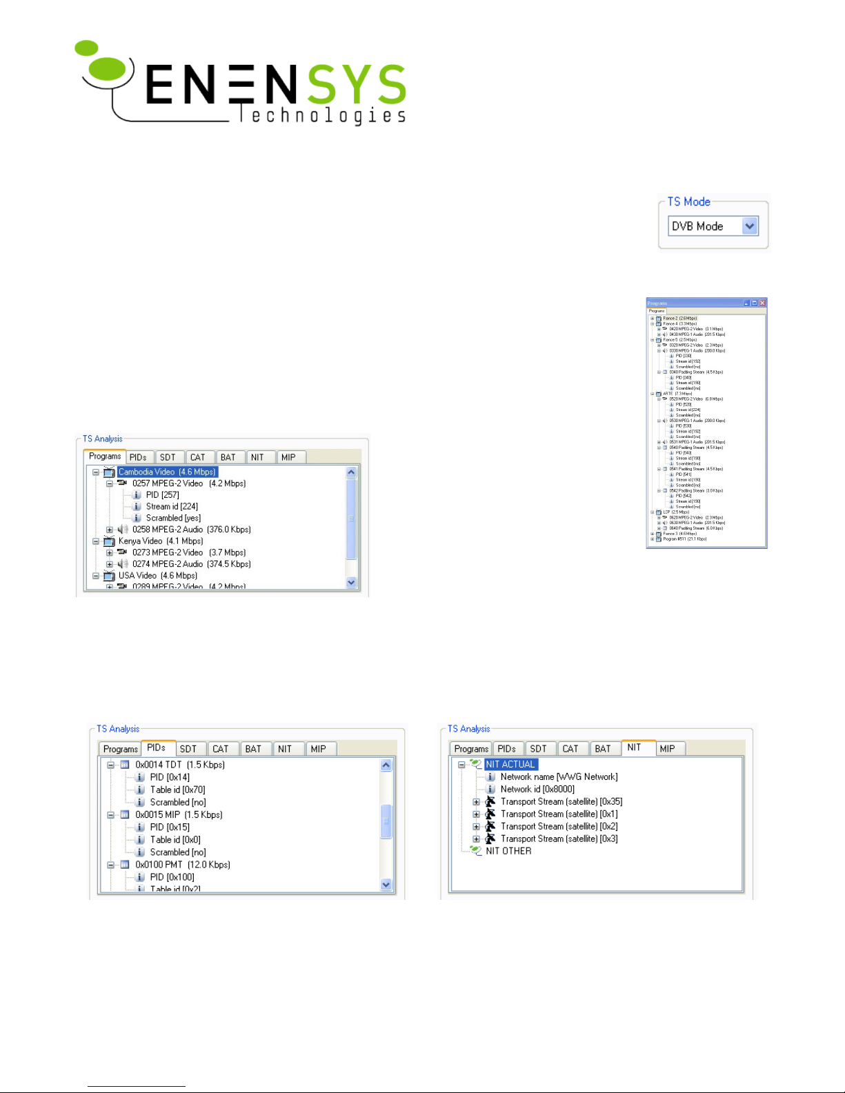
Analysis modes: DVB and ATSC
Two modes for interpreting MPEG2-TS signalling are available: DVB and ATSC. DVB
Mode is used for interpreting PSI/SI signalling, and ATSC mode is used for interpreting
PSIP/SI signalling. Switching between modes is performed through the TS Mode drop-
down list
General use
All tabs can be detached for a more comfortable viewing through a drag-and-drop of
the tab outside of the TS analysis section. This viewing is especially useful to real-
time monitor a specific table at the same time as a different table or RF parameter.
All tabs can be detached and become independent windows. Close a detached tab to
reintegrate it to the list of tabs inside the TS Analysis section.
“Programs” tab displays all the services
contained within the stream. In this
case, 3 programs are detected
(“Cambodia”, “Kenya” and “USA”
video). Several information are given
such as PID, stream_id, scrambled or
not...
DVB Mode (PSI/SI Signalling)
Other tabs provide advanced analysis. SDT, CAT, BAT, NIT, TDT and TOT tabs provide PSI/SI table
parsing.
The MIP tab provides parsing of Mega Frame Initialization Packets that are used to synchronize all
transmitters making up a single frequency network.
Real time PID monitoring Network Information Table analysis
ENENSYS DiviCatch RF - Manual Page 9 / 40
DiviCatch RF
User Guide
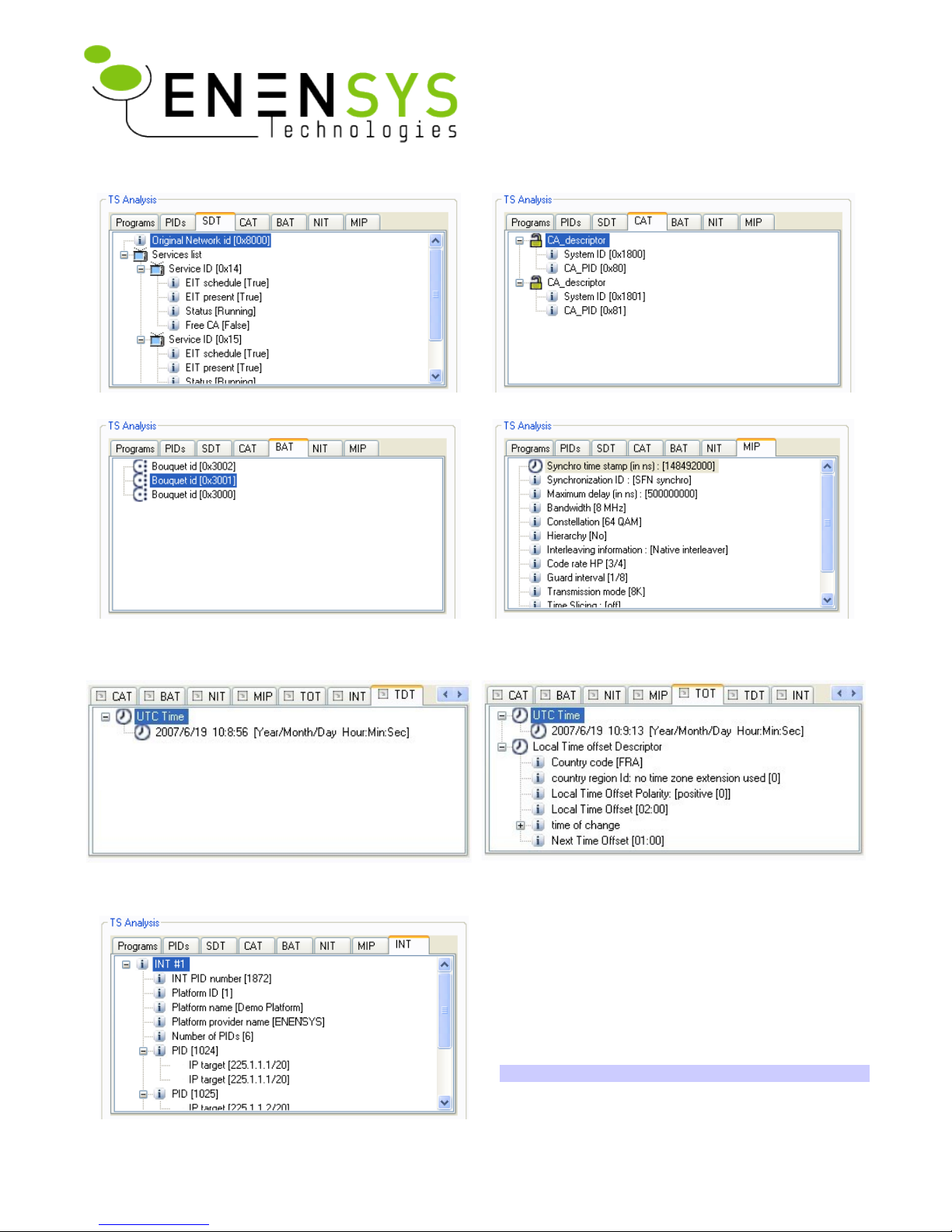
Service Description Table analysis Conditional Access Table analysis
Bouquet Association Table analysis Mega Frame Initialisation Packet analysis
(including real-time Synchro Time Stamps info)
Note: Not relevant for Cable-modulated signals
Time and Date Table
Embedded UTC time and date stamp in the TS.
Time Offset Table
Embedded indication of local time offset
The last tab, “INT” provides information about all
the parameters contained inside the IP/MAC
Notification Table, which is a DVB-H specific table
providing a description of IP streams contained
within the multiplex.
Note: Only available for DVB-H formatted signals
ENENSYS DiviCatch RF - Manual Page 10 / 40
DiviCatch RF
User Guide
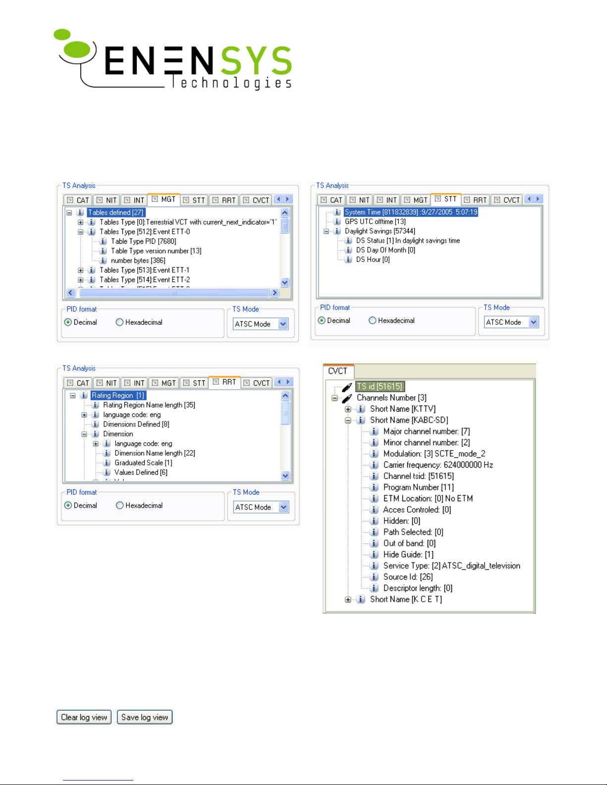
ATSC Mode (PSIP/SI Signalling)
Some signalling tables are common in ATSC mode and DVB mode: CAT and NIT.
The follwing tables, specific to PSIP signalling, are available for parsing in Divicatch application.
MGT (Master Guide Table)
STT (System Time Table)
RRT (Rating Region Table)
CVCT (Cable Virtual Channel Table)
How to use Log information?
Log view
By default, log information consists of the log view in the Monitoring
& Log panel. This view can store up to 1,000 messages. This log view
ENENSYS DiviCatch RF - Manual Page 11 / 40
DiviCatch RF
User Guide
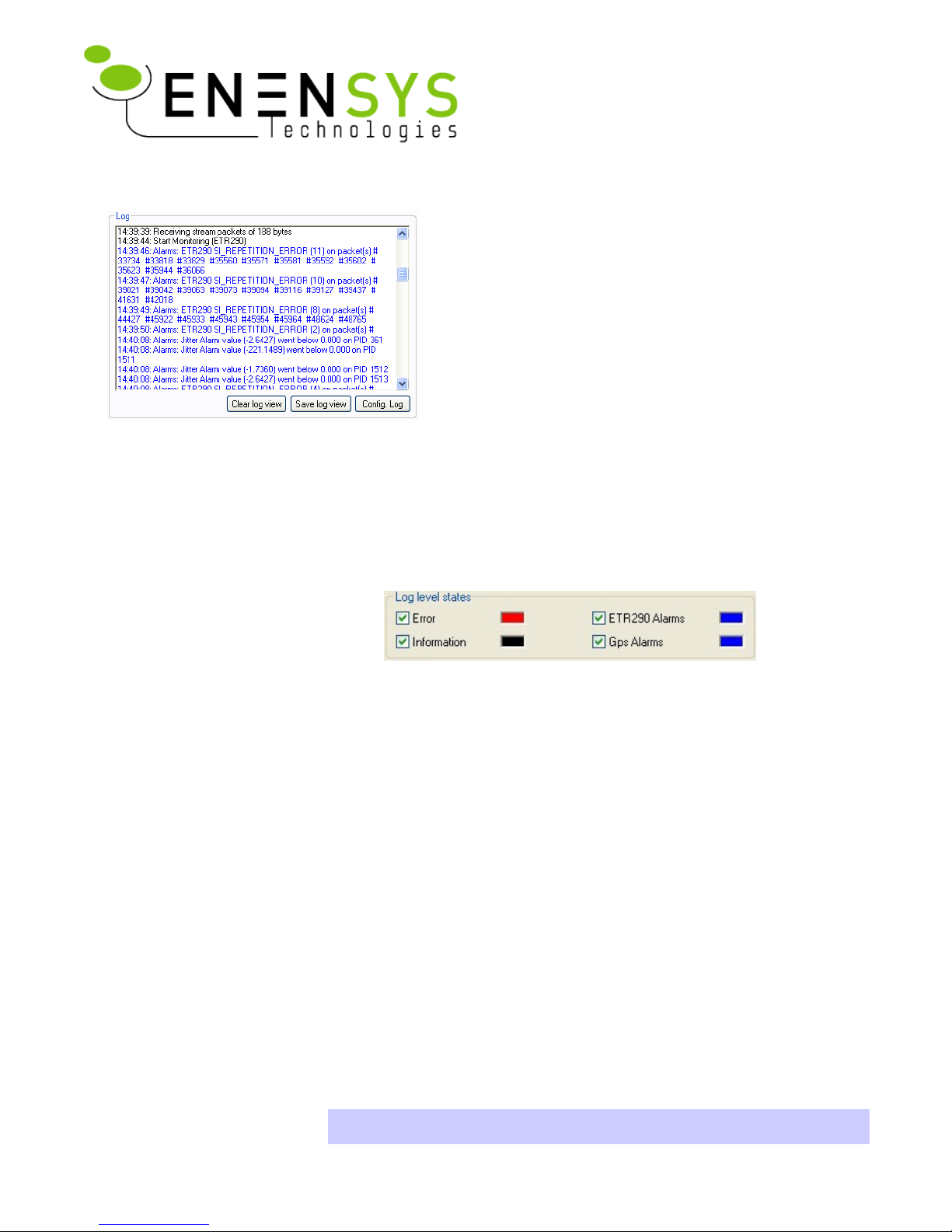
can be cleared (Clear Log View) or saved (Save Log View).
Depending on the level of information required,
the type of messages to be displayed can be
selected. Also, for the comfort of viewing, log font
color can also be selected for each level of log
information.
● Click Config Log. A “Log configuration”
window opens.
● Select the level of information to be logged: Check each level for which
you would like to view log messages. “Error” (Stream reception errors,
etc.), “Information” (stream reception info, settings changes, etc.),
“ETR290” (ETR290 logs requested individually from the ETR290 tab),
“GPS alarms” (GPS log information, only available with DiviCatch RF-
T/H GPS option).
● Click the colored square at the right of the log level. A color selection
dialog opens. Choose the color to be used for the associated state.
● Click Ok. The “Log configuration” window closes. Settings are applied.
Log file (Continuous monitoring)
A log file feature is also available for continuous monitoring needs.
● Click Config Log. A “Log configuration” window opens.
● As for the log view (see previous section), select the level of information
to be logged.
● Check the “Use log file” box.
● Enter a path and file name for the log files to be created.
● Choose between logging file size and duration for the creation of a new
log file. For example, choosing a “Max file size” of 1MB will create a new
log file every time 1MB is reached. File names are incremented with
numbers (eg, file_name1.log, file_name2.log, etc.)
Note: Log files will be created as long as the Use log file box is checked.
To stop the logging of information, open the log configuration dialog and
ENENSYS DiviCatch RF - Manual Page 12 / 40
DiviCatch RF
User Guide
 Loading...