

Page 1
intelligent reliable power
E n e c sys Mi c r o-In v e r te r s
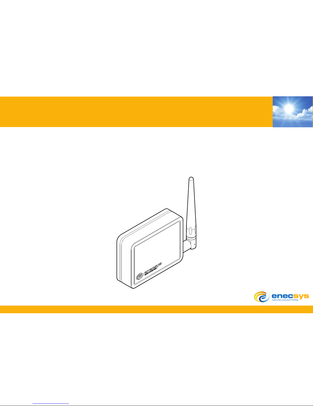
Double Repeater User Manual
Version 1.0
Page 2

DRAFT
DRAFT
D
RAFT
DR
DRAFT
D
RAFT
DRAFT DRAF
DRAFT DRAFT DRAFT DRA
FT
D
RAFT D
DRAFT
D
RAFT
DRAFT DRAFT DRAFT
DRA
F
T DRA
Double Repeater User Manual Intelligent Reliable Power
1
© ENECSYS 2010. All rights reserved.
CONTENTS
Introduction 1
Conventions used in this manual 2
Safety 3
Scope of delivery 4
Enecsys Double Repeater 5
When to install an Enecsys Double Repeater 5
Installation 6
Attaching the internal antenna 7
Mounting the Enecsys Double Repeater 8
Wall mounting the Enecsys Double Repeater (adhesive pad method) 9
Wall mounting the Enecsys Double Repeater (screw fixed method) 10
Mounting with a cable tie 11
Installing the external antenna 12
Turning the Enecsys Double Repeater on 13
Turning the Enecsys Double Repeater off 14
Technical specification 15
Compliance 18
Printing 19
Page 3

DRAFT
DRAFT
D
RAFT
DR
DRAFT
D
RAFT
DRAFT DRAF
DRAFT DRAFT DRAFT DRA
FT
D
RAFT D
DRAFT
D
RAFT
DRAFT DRAFT DRAFT
DRA
F
T DRA
Double Repeater User Manual Intelligent Reliable Power
1
© ENECSYS 2010. All rights reserved.
1. Introduction
This manual contains information specific to the installation of an Enecsys Double Repeater.
Although the installation is simple a basic knowledge of internet routers, wired or wireless may
be beneficial although not necessary. Installation of the Enecsys Double Repeater is a 'plug and
play'. Enecsys have designed the hardware to be a simple as possible for the installer and enduser alike.
Your solar PV (photo-voltaic) installation, when combined with an Enecsys Micro-Inverter with its
in-built wireless antenna is able to communicate wirelessly with the Gateway. This allows for
comprehensive monitoring of the solar PV array, module-by-module.
Monitoring an array module by module enables the user to see energy generation at module
level. Monitoring also allows the end-user to see the performance of any module at any time of
the day.
An Enecsys Double Repeater acts as a bridge between the Micro-inverter and the Gateway in
situations where a sufficient communication link cannot be established.
For circumstances where it may be necessary to install an Enecsys Double Repeater, See“When
to install an Enecsys Double Repeater” on page 5.
Page 4

DRAFT
DRAFT DRAFT
DR
DRAFT DRAFT
DR
AFT
DRAF
DRAFT DRAFT DRAFT DRA
FT
D
RAFT D
DRAFT DRAFT DRAFT
D
RAFT DRA
F
T DRAFT DRA
Double Repeater User Manual Intelligent Reliable Power
2
© ENECSYS 2010. All rights reserved.
1.1 Conventions used in this manual
The following conventions are used throughout this manual, these conventions should be noted
and followed at all times.
Warning: Warning statements must be heeded at all times. A warning symbol indicates that a
process or instrument has the potential to harm or cause lethal injury if the correct method of
handling is not employed.
Caution: Caution statements are used to indicate where a part of the installation process may
require special attention. Caution statements should be followed at all times.
Attention: Attention statements are used to indicate where a part of the process or instrument
has a special requirement. Attention statements should be followed at all times.
Page 5

DRAFT
DRAFT
D
RAFT
DR
DRAFT
D
RAFT
DRAFT DRAF
DRAFT DRAFT DRAFT DRA
FT
D
RAFT D
DRAFT
D
RAFT
DRAFT DRAFT DRAFT
DRA
F
T DRA
Double Repeater User Manual Intelligent Reliable Power
3
© ENECSYS 2010. All rights reserved.
1.2 Safety
Before installing and using the any Enecsys Repeater please ensure that you have fully read and
understand all of the installation and user instructions and heed all warnings and cautions given.
Install in a clean dry environment, indoors and if possible away from heat sources and out of
direct sunlight.
• All electrical installations should be performed in accordance with all local and national electrical installation codes and practice.
• There are no user serviceable parts inside this unit.
• There are no replaceable or re-chargeable batteries contained within the Repeater.
• Do not attempt to open the unit. Tampering with the Repeater may result in electrical shock
or death.
• Do not install this equipment in adverse weather conditions or in a wet environment.
• Do not install this equipment during an electrical storm.
Page 6

DRAFT
DRAFT DRAFT
DR
DRAFT DRAFT
DR
AFT
DRAF
DRAFT DRAFT DRAFT DRA
FT
D
RAFT D
DRAFT DRAFT DRAFT
D
RAFT DRA
F
T DRAFT DRA
Double Repeater User Manual Intelligent Reliable Power
4
© ENECSYS 2010. All rights reserved.
1.3 Scope of delivery
The following list details the scope of delivery, please ensure that all parts are present before
starting the installation.
A. 1 x Enecsys Double Repeater.
B. 1 x Fixed antenna.
C. 1 x External antenna.
D. 1 x Coaxial cable reverse polarity with RP SMA connectors, 15 - 30 meter lengths.
E. 1 x Plug-top 5V DC, 1A adaptor with 2.1mm jack.
F. 3 x Double sided adhesive pads.
FIGURE 1.
Scope of delivery.
?
A B D E
F
C
Page 7

DRAFT
DRAFT
D
RAFT
DR
DRAFT
D
RAFT
DRAFT DRAF
DRAFT DRAFT DRAFT DRA
FT
D
RAFT D
DRAFT
D
RAFT
DRAFT DRAFT DRAFT
DRA
F
T DRA
Double Repeater User Manual Intelligent Reliable Power
5
© ENECSYS 2010. All rights reserved.
1.4 Enecsys Double Repeater
The Enecsys Double Repeater provides a ‘hop’ between nodes in a network. The Enecsys Double
Repeater is used to allow communication between the Micro-inverters and Gateway where the
propagation losses are too high for a reliable communication link, particularly where metallic
structures prevent RF propagation. There are various implementations of Enecsys Double
Repeaters, more than one Enecsys Double Repeater can be used to cover larger distances. An
Enecsys Double Repeater differs from a Single Repeater in that two antennas are used. One
antenna can be connected via coaxial cable to an external antenna, positioned on the roof, close
to the inverters. The second antenna communicates with the Gateway located in the house.
1.5 When to install an Enecsys Double Repeater
Depending upon the house construction and build materials it may be necessary to add an
Enecsys Double Repeater in order to provide stable communications between the inverters and
the Gateway over a long time period. An Enecsys Double Repeater is used in situations where a
Single Repeater is unable to provide the Gateway with a strong sustainable communication link.
The Enecsys Double Repeater acts a bridge between the Micro-inverter and the Gateway,
improving the communication link and providing an uninterrupted flow of information between
the two devices. Certain building materials can prevent a strong signal from being established in
the communication link.
• A roof may be made out a metallic material or be a foil insulated.
• The distance between the micro-inverters and the wireless antenna is too great.
• UV screened windows.
Page 8
DRAFT
DRAFT DRAFT
DR
DRAFT DRAFT
DR
AFT
DRAF
DRAFT DRAFT DRAFT DRA
FT
D
RAFT D
DRAFT DRAFT DRAFT
D
RAFT DRA
F
T DRAFT DRA
Double Repeater User Manual Intelligent Reliable Power
6
© ENECSYS 2010. All rights reserved.
2. Installation
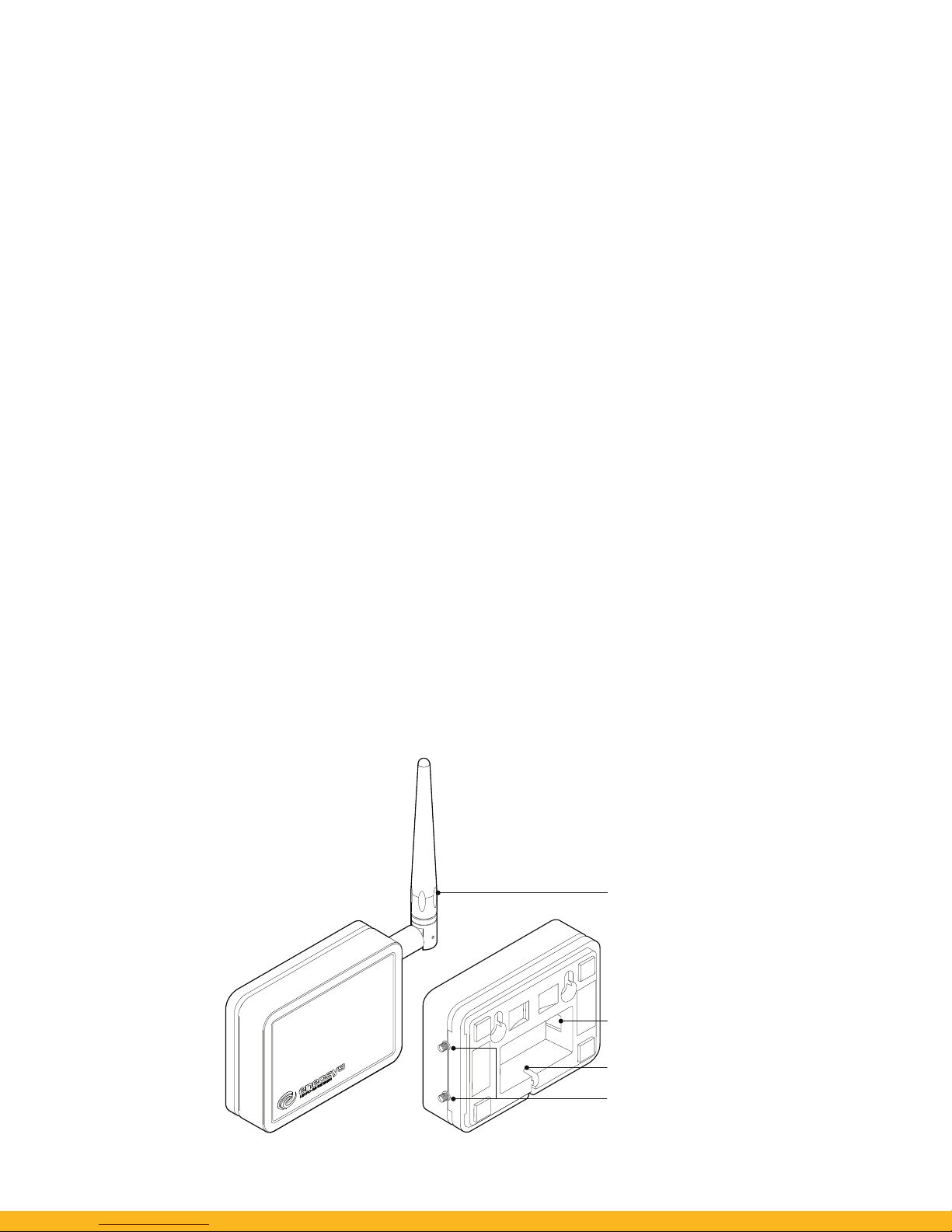
Enecsys Double Repeaters are employed to improve the communication link between the
inverters and the Gateway. The Enecsys Double Repeater is a 'plug and play' device; it is quickly
and easily installed. The Enecsys Double Repeater should be installed within the roof-space of the
building and positioned within easy connection distance of a mains supply AC power source.
FIGURE 2.
The Enecsys Double Repeater.
5V DC IN
POWER CABLE
CONDUIT
RP SMA
CONNECTORS
ANTENNA
Page 9
DRAFT
DRAFT
D
RAFT
DR
DRAFT
D
RAFT
DRAFT DRAF
DRAFT DRAFT DRAFT DRA
FT
D
RAFT D
DRAFT
D
RAFT
DRAFT DRAFT DRAFT
DRA
F
T DRA
Double Repeater User Manual Intelligent Reliable Power
7
© ENECSYS 2010. All rights reserved.
2.1 Attaching the internal antenna
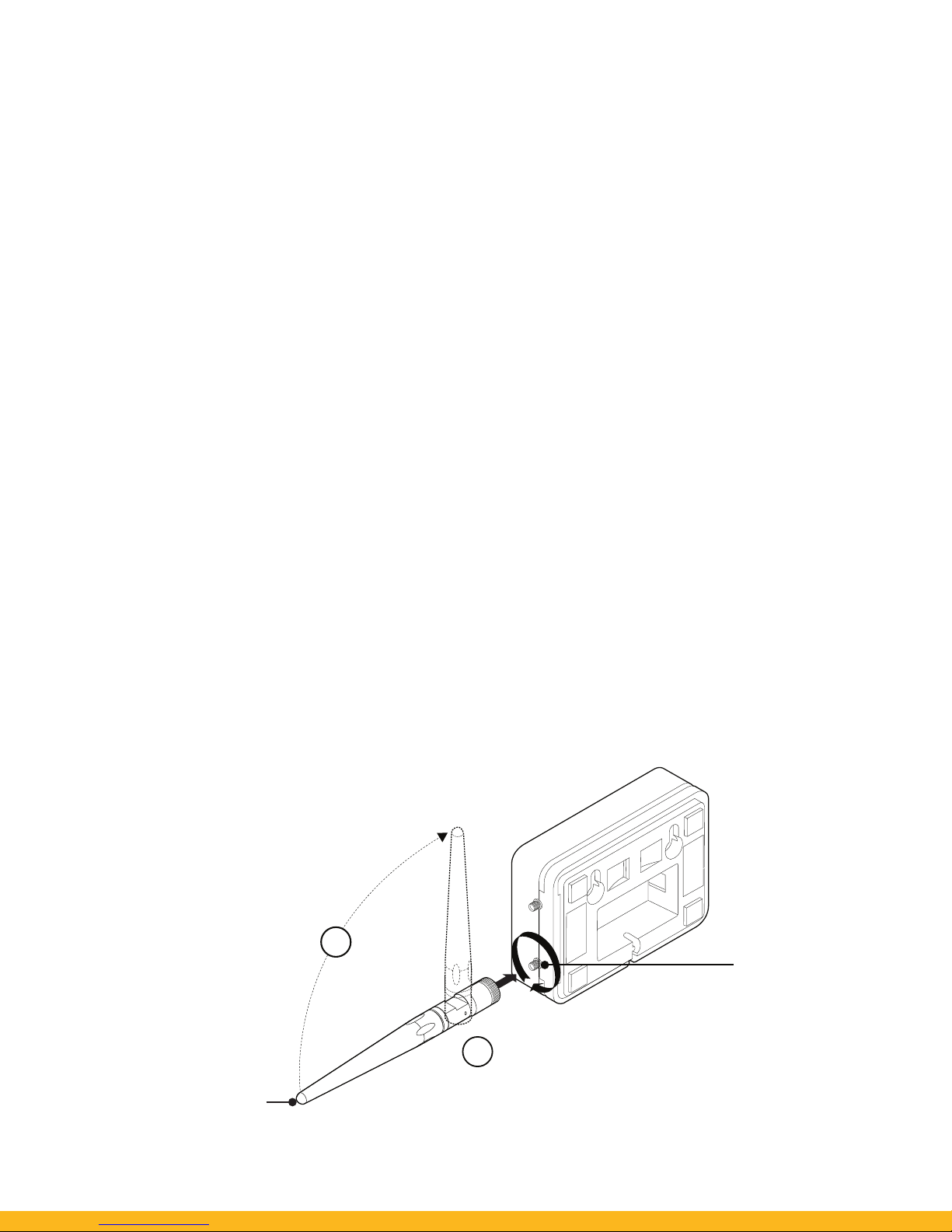
Attach the antenna to the RP SMA connector on the right hand side of the Enecsys Gateway.
1. Attach the antenna to the lower SMA plug on the right hand side of the Repeater, screw the
antenna into place in a clockwise direction.
2. Move the antenna into an upright position.
FIGURE 3.
Attaching the antenna.
1
2
A
NTENNA
RP SMA
CONNECTOR
Page 10
DRAFT
DRAFT DRAFT
DR
DRAFT DRAFT
DR
AFT
DRAF
DRAFT DRAFT DRAFT DRA
FT
D
RAFT D
DRAFT DRAFT DRAFT
D
RAFT DRA
F
T DRAFT DRA
Double Repeater User Manual Intelligent Reliable Power
8
© ENECSYS 2010. All rights reserved.
2.2 Mounting the Enecsys Double Repeater
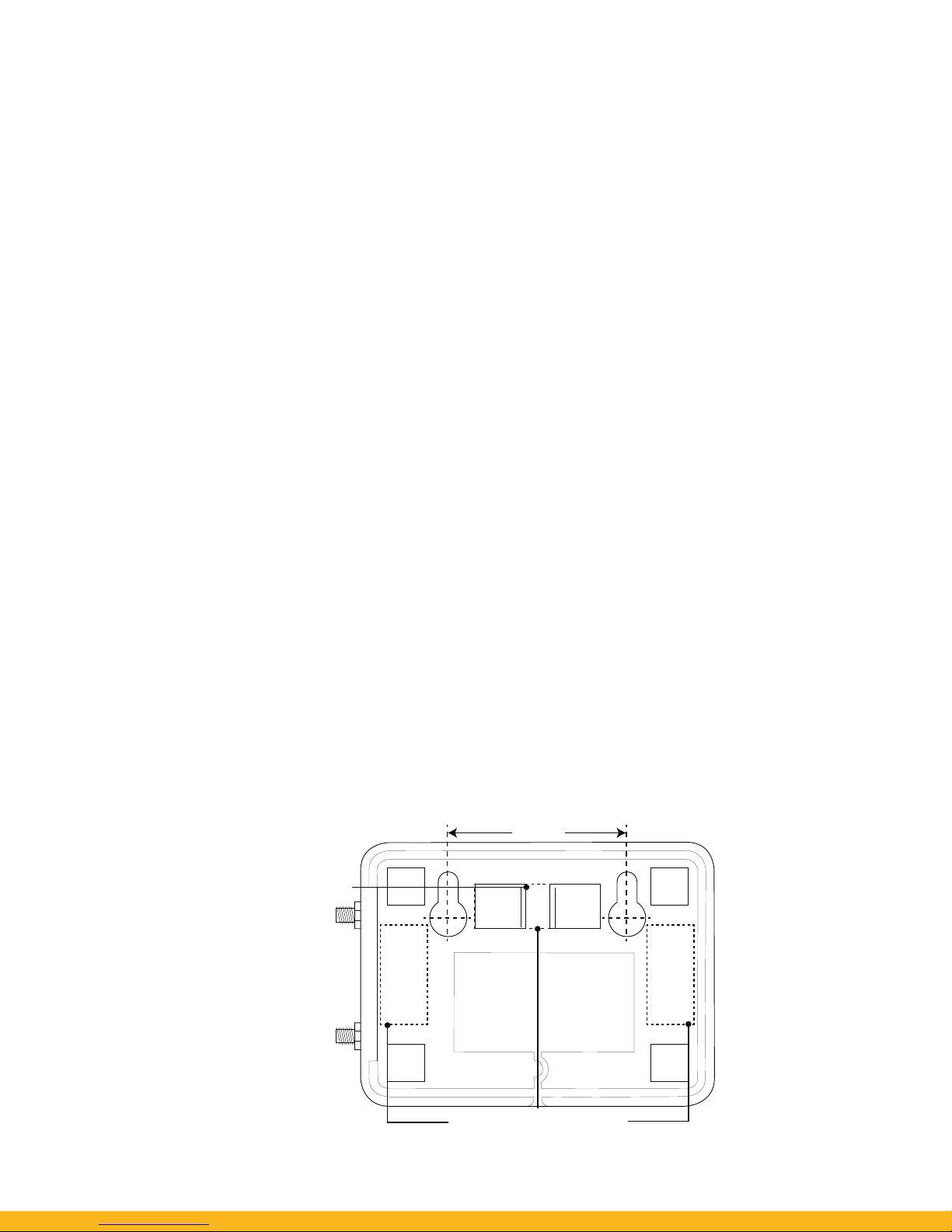
The Enecsys Double Repeater can be either free standing or wall mounted. In each case the
Enecsys Double Repeater should be installed in a location where it is unlikely to be moved,
indoors, away from heat sources and out of direct sunlight. If choosing a free standing Enecsys
Double Repeater installation simply place the Enecsys Double Repeater within reach of a power
source. It is recommended that the Enecsys Double Repeater be placed as high as possible within
the building such as the loft space.
FIGURE 4.
The Enecsys Double Repeater reverse showing mounting points and distances.
ADHESIVE FIXING POINTS
50 mm
CABLE TIE
FIXING POINT
Page 11

DRAFT
DRAFT
D
RAFT
DR
DRAFT
D
RAFT
DRAFT DRAF
DRAFT DRAFT DRAFT DRA
FT
D
RAFT D
DRAFT
D
RAFT
DRAFT DRAFT DRAFT
DRA
F
T DRA
Double Repeater User Manual Intelligent Reliable Power
9
© ENECSYS 2010. All rights reserved.
2.3 Wall mounting the Enecsys Double Repeater (adhesive pad method)
When mounting an Enecsys Double Repeater always ensure that you have connected the power
supply and antenna to the device before the final fit. Locate the Enecsys Double Repeater away
from metal structures.
The adhesive pad placement areas are shown in Figure 4 on page 8.
1. Ensure that the back-plate of the Enecsys Double Repeater and the wall or mounting surface
is clean from dust and grease.
2. Connect the supplied external 5V DC power supply to a mains supply AC power source.
3. Connect the supplied external 5V DC power jack-plug to the DC power port on the reverse of
the Enecsys Double Repeater, thread the cable through the semi-circular channel on the backplate of the Enecsys Double Repeater, this will help to keep the cable in place and prevent it
from becoming detached.
4. Remove the backing material from one of the double sided adhesive pads and place firmly
onto the fixing points on the back of the Enecsys Double Repeater. Complete the process for
the remaining two double sided adhesive pads.
5. Remove the remaining backing material from the adhesive pads attached to the back-plate of
the Enecsys Double Repeater, press the Enecsys Double Repeater firmly into place on the
wall/mounting surface.
Page 12

DRAFT
DRAFT DRAFT
DR
DRAFT DRAFT
DR
AFT
DRAF
DRAFT DRAFT DRAFT DRA
FT
D
RAFT D
DRAFT DRAFT DRAFT
D
RAFT DRA
F
T DRAFT DRA
Double Repeater User Manual Intelligent Reliable Power
10
© ENECSYS 2010. All rights reserved.
2.4 Wall mounting the Enecsys Double Repeater (screw fixed method)
When mounting an Enecsys Double Repeater always ensure that you have connected the power
supply and antenna to the device before the final fit.
The screw fixing points are shown in Figure 4 on page 8.
1. Attach the antenna to the SMA plug on the right hand side of the Enecsys Double Repeater,
screw the antenna into place in a clockwise direction.
2. Connect the 5V DC power supply jack-plug to the DC power port on the reverse of the Enecsys
Double Repeater, thread the cable through the semi-circular channel on the back-plate of the
Enecsys Double Repeater, this will help to keep the cable in place and prevent it from becoming detached.
3. Select the appropriate location for mounting the Enecsys Double Repeater.
4. Using the wall mount template locate the desired position of the Enecsys Double Repeater;
ensure that there is adequate free-space around the Enecsys Double Repeater to allow for
any future movement or maintenance of the device.
5. Mark two horizontal spots on the wall 50 millimetres apart, install the screws into the wall.
6. Line up the back plate holes of the Enecsys Double Repeater with the screws on the wall and
then slide the Enecsys Double Repeater down to fix the unit in position.
Page 13
DRAFT
DRAFT
D
RAFT
DR
DRAFT
D
RAFT
DRAFT DRAF
DRAFT DRAFT DRAFT DRA
FT
D
RAFT D
DRAFT
D
RAFT
DRAFT DRAFT DRAFT
DRA
F
T DRA
Double Repeater User Manual Intelligent Reliable Power
11
© ENECSYS 2010. All rights reserved.
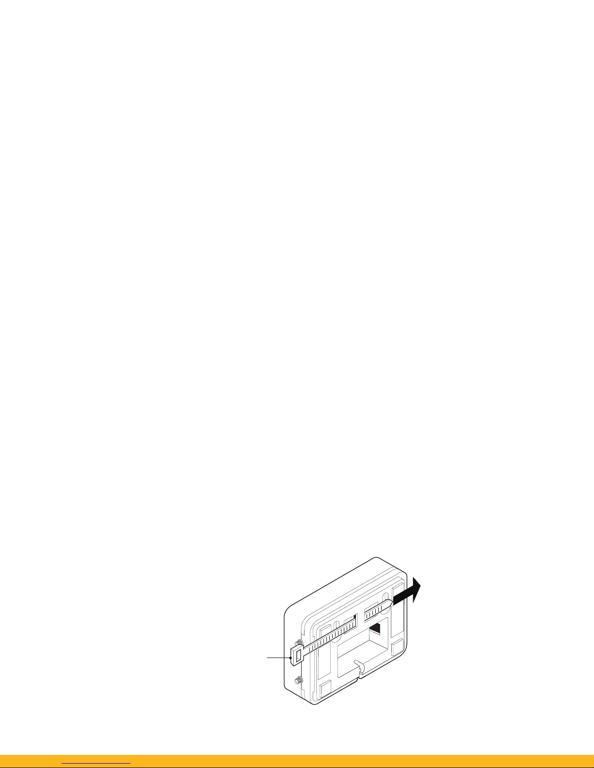
2.5 Mounting with a cable tie
When mounting a Enecsys Double Repeater always ensure that you have connected the power
supply and antenna to the device before the final fit.
There may be situations where it is not possible to mount the Enecsys Double Repeater using the
screw fixed or adhesive pad method. A cable tie can be utilised to fix the Enecsys Double Repeater
to an internal pillar or suitable structure.
1. Ensure that the cable tie is of the correct width and length.
2. Run the cable tie through the cable tie fixing point on the back of the Enecsys Double
Repeater.
3. Wrap the cable tie around the internal pillar or suitable mounting object and secure.
FIGURE 5.
Mounting with a cable tie.
CABLE TIE
Page 14

DRAFT
DRAFT DRAFT
DR
DRAFT DRAFT
DR
AFT
DRAF
DRAFT DRAFT DRAFT DRA
FT
D
RAFT D
DRAFT DRAFT DRAFT
D
RAFT DRA
F
T DRAFT DRA
Double Repeater User Manual Intelligent Reliable Power
12
© ENECSYS 2010. All rights reserved.
2.6 Installing the external antenna
When installing an external antenna always make sure that cable entry to building is
waterproofed.
Always ensure that the cable isn't arranged such that water or condensate can run down coaxial
cable and onto the repeater.
1. Ensure that you have enough coaxial cable to reach from the mounting point to the Enecsys
Double Repeater.
2. Secure the external antenna to the mounting rack of the solar array or other suitable structure using two self-tapping screws. Cable ties may also be used to hold the antenna in a
secure position.
3. Connect the co-ax cable the bottom of the external antenna and screw into place.
4. Feed the coaxial cable through the installed cabling conduit and into the loft space of the
building, use cable ties to hold the co-axial cable in place.
5. Connect the SMA connector (male) to the upper SMA connector (female) on right hand side
of the Enecsys Double Repeater, screw the connector into place in a clockwise direction.
6. Secure the external coaxial.
Page 15
DRAFT
DRAFT
D
RAFT
DR
DRAFT
D
RAFT
DRAFT DRAF
DRAFT DRAFT DRAFT DRA
FT
D
RAFT D
DRAFT
D
RAFT
DRAFT DRAFT DRAFT
DRA
F
T DRA
Double Repeater User Manual Intelligent Reliable Power
13
© ENECSYS 2010. All rights reserved.
2.7 Turning the Enecsys Double Repeater on
The Enecsys Double Repeater comes supplied with an external 5V DC power supply. The power
adaptor serves as the disconnect device - a socket outlet in accordance to the national wiring
codes for the country shall be installed near the equipment and shall be easily accessible.
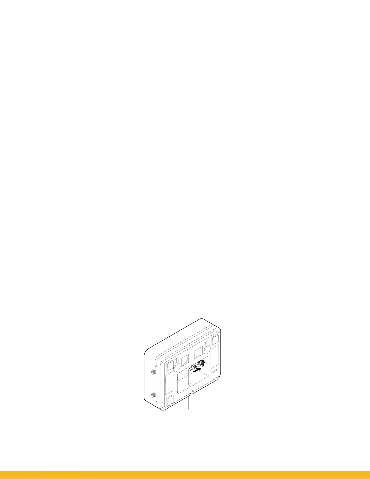
To turn the Enecsys Double Repeater on feed the power cable through the power cable conduit,
attach the 5V DC power supply jack-plug from the power port on the reverse of the Repeater.
FIGURE 6.
Connecting the Enecsys Double Repeater’s power supply.
5V DC IN
Page 16
DRAFT
DRAFT DRAFT
DR
DRAFT DRAFT
DR
AFT
DRAF
DRAFT DRAFT DRAFT DRA
FT
D
RAFT D
DRAFT DRAFT DRAFT
D
RAFT DRA
F
T DRAFT DRA
Double Repeater User Manual Intelligent Reliable Power
14
© ENECSYS 2010. All rights reserved.
2.8 Turning the Enecsys Double Repeater off
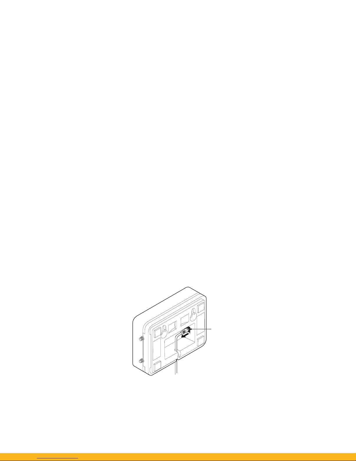
The Enecsys Double Repeater comes supplied with a 5V DC external power supply. The power
adaptor serves as the disconnect device - a socket outlet in accordance to the national wiring
codes for the country shall be installed near the equipment and shall be easily accessible.
FIGURE 7.
Disconnecting the Enecsys Double Repeater’s power supply.
5V DC
DISCONNECT
Page 17

DRAFT
DRAFT
D
RAFT
DR
DRAFT
D
RAFT
DRAFT DRAF
DRAFT DRAFT DRAFT DRA
FT
D
RAFT D
DRAFT
D
RAFT
DRAFT DRAFT DRAFT
DRA
F
T DRA
Double Repeater User Manual Intelligent Reliable Power
15
© ENECSYS 2010. All rights reserved.
3. Technical specification
Power
Mains Plug-top P.S.U.
Input: 100-240V AC 50-60Hz 0.3A.
Output; 5V DC, 1.2A. with 2.1mm jack.
Table 1: Power adapter.
Operating Temperature
Temperature range 10°C to +40°C.
Table 2: Operating temperature.
Interface Specifications
Ethernet Interface RJ45, 10Base-T or 100Base-TX.
Table 3: Interface specification.
Page 18

DRAFT
DRAFT DRAFT
DR
DRAFT DRAFT
DR
AFT
DRAF
DRAFT DRAFT DRAFT DRA
FT
D
RAFT D
DRAFT DRAFT DRAFT
D
RAFT DRA
F
T DRAFT DRA
Double Repeater User Manual Intelligent Reliable Power
16
© ENECSYS 2010. All rights reserved.
Life Expectancy
Usable lifetime 12 months warranty.
Table 4: Life expectancy.
Fixed Internal Antenna
Radiating element 1/2 Wave Element.
Frequency range 2.4 GHz.
Peak gain 2.0 dBi.
Polarisation Linear.
Connector SMA Male.
Dimensions 139 x 13mm.
Table 5: Fixed antenna.
Page 19

DRAFT
DRAFT
D
RAFT
DR
DRAFT
D
RAFT
DRAFT DRAF
DRAFT DRAFT DRAFT DRA
FT
D
RAFT D
DRAFT
D
RAFT
DRAFT DRAFT DRAFT
DRA
F
T DRA
Double Repeater User Manual Intelligent Reliable Power
17
© ENECSYS 2010. All rights reserved.
*External Antenna - For adetailed technical description of installation of the external antenna
please refer to external antenna installation guide.
*External Antenna
Radiating element 1/2 Wave Element
Frequency range 2.4 GHz
Peak gain 2.0 dBi
Polarisation Linear
Return loss -13 dB
Connector SMA Male
Dimensions 139 x 13mm
Table 6: External Antenna.
Page 20

DRAFT
DRAFT DRAFT
DR
DRAFT DRAFT
DR
AFT
DRAF
DRAFT DRAFT DRAFT DRA
FT
D
RAFT D
DRAFT DRAFT DRAFT
D
RAFT DRA
F
T DRAFT DRA
Double Repeater User Manual Intelligent Reliable Power
18
© ENECSYS 2010. All rights reserved.
4. Compliance
Enecsys Double Repeaters conform to the following compliance codes.
IC: 9052A-DEREP01
FCC: YIWDEREPEATER0001
Operation is subject to the following two conditions: (1) this device may not cause harmful
interference, and (2) this device must accept any interference, including interference that may
cause undesired operation of the device.
Changes or modifications made to this device that are not expressly approved by Enecsys Ltd may
void the user's authority to operate the equipment.
Electrical Product Safety
IEC 60950-1:2005 (2nd Edition); Am 1:2009;
Compliance with National Differences :IEC60950_1B attachment EN60950-1:2006/A11:2009/
A1:2010
EMC
EN 301 489-17 V2.1.1 - ElectroMagnetic compatibility and Radio spectrum Matters (ERM);
ElectroMagnetic Compatibility (EMC) standard for radio equipment and services; Part 1: Common
Technical Requirements.
Spectrum
EN 300 328 V1.7.1 - (Radio Module) Electromagnetic Compatibility and Radio Spectrum Matters
(ERM) Wideband transmission systems; Data transmission equipment operating in the 2.4GHz
Page 21

DRAFT
DRAFT
D
RAFT
DR
DRAFT
D
RAFT
DRAFT DRAF
DRAFT DRAFT DRAFT DRA
FT
D
RAFT D
DRAFT
D
RAFT
DRAFT DRAFT DRAFT
DRA
F
T DRA
Double Repeater User Manual Intelligent Reliable Power
19
© ENECSYS 2010. All rights reserved.
ISM band and using wideband modulation techniques; Harmonised EN covering essential
requirements under article 3.2 of the R&TTE Directive.
5. Printing
Please print this manual once and then keep it in a safe place for future reference.
If you intend to dispose of this manual please recycle.
Page 22

Enecsys Limited
Harston Mill, Royston Rd
Cambridge, CB22 7GG, UK
www.enecsys.com
Registered Office:
Enecsys Limited, 24 Hills Road,
Cambridge, CB2 1JP, England
Registration No: 04832321
Document reference: ENEC-DOC-012
 Loading...