

Page 1
Enea
Analogue-addressable fire detectors
ED100 - optical smoke detector
ED200 - temperature detector
ED300 - multicriteria detector
ATTENTION!
For information regarding device placement, coverage and method of installation, refer
to the established standard regulations and codes relating to Automatic fire-detection
systems. Enea series detectors are compliant with EN54-7: Smoke detectors – Point
detectors using the scattered light principle, light transmission or ionization (ED100 and
ED300 models only) and EN54-5: Heat detectors – point detectors (for ED200 and
ED300 models only), EN54-17 short-circuit isolators.
Product description
Enea series detectors are capable of sensing a number of combustion products suspended in the atmosphere and
thus the onset of fires.
The operating parameters of these detectors can be changed, via the connected control panel, to suit specific
environment conditions. These detectors are connected to the fire control panel via a 2 pole twisted-shielded
cable. The cable carries the power supply to the various devices and also the two-way digital transmission data.
Each detector has a short-circuit isolator that, in the event of short-circuit between the two poles and the control
panel (loop), is capable of interrupting the negative pole, thus isolating the section involved in the short-circuit
event. For the isolator specification, please refer to the “ILP Specification” document.
INIM Electronics offers three Enea series analogue fire-detectors, which can be identified by the Technical
specifications/ Serial number sticker on the back of the device.
ED100
Optical detector equipped with a reference chamber based on the
scattered light principle (Tyndall effect). The detector must be installed in
draught and obstacle free place which guarantees appropriate air-flow
into the reference chamber.
The detector will trigger an alarm when the level of smoke inside the
reference chamber reaches the alarm values set for the detector in the
control panel:
•0.08 dB/m
•0.10 dB/m
• 0.12 dB/m (pre-set mode)
•0.15 dB/m
ED200
Heat detector with heat-sensitive element capable of sensing the
temperature within the protected environment.
The programmable operating modes are:
• “A1R” (pre-set); the detector signals alarm status when the temperature
within the protected environment exceeds 58 °C or when the temperature
undergoes anomalous changes.
• “B”; the detector signals alarm status when the temperature within the
protected environment exceeds 72°C.
• “A2S”; the detector signals alarm status when the temperature within in the
protected environment exceeds 58°C.
• “BR”; the detector signals alarm status when the temperature within the
protected environment exceeds 72° or when it senses a rapid temperature
rise.
ATTENTION!
The operating modes of the “A2S” and “BR” are not certified.
ED100
ADDRESSABLE
SMOKE DETECTOR
EN54-7:2000
EN54-17:2005
2010/09
FW.01.01
*00000004*
ED100 00000004 ED100 00000004
0832-CPD-1448
991d/01
00000004
ED200
ADDRESSABLE
HEAT DETECTOR
HEAT DETECTOR CLASS P
EN54-5:2000
EN54-17:2005
2010/09
FW.01.01
*00000005*
ED200 00000005 ED200 00000005
0832-CPD-1450
991f/01
00000005
DCMIIN4AED-R100-20110519
0832-CPD-1448
0832-CPD-1450
0832-CPD-1446
991d/01
991f/01
991b/01
Page 2

2
Enea
ED300
Opto-heat detector with and optical reference chamber and heat sensitive
element. The combination of values provides (in accordance with the
operating mode selected via the control panel) high immunity to nuisance
alarms and an exceptionally sensitive detector which is capable of swift
response to developing fires characterized by low smoke emission.
The operating modes, programmable via the control panel are:
• “PLUS” (pre-set); the detector signals alarm status when smoke in the protected
environment exceeds the programmed threshold (programmed as described for
the ED100 model) or when the temperature within the protected environment
exceeds the programmed threshold (programmed as described for the model
ED200). Furthermore, in the event of a rise in temperature within the protected
environment, the sensitivity of the smoke chamber will be increased. This
operating mode, characterized by high sensitivity, allows detection of fires which
produce a large amount of flames but low smoke emission (e.g. combustion of
alcohol or similar highly-inflammable products) .
• “OR”; the detector signals alarm status when smoke in the protected environment exceeds the programmed threshold
(programmed as described for the ED100 model) or when the temperature within the protected environment exceeds the
programmed threshold (programmed as described for the ED200 model). This operating mode, characterized by mediumhigh sensitivity, allows detection of fires which generate a substantial amount of smoke but low heat emission (slow
burning fires) as well as fires which generate high temperatures and low smoke emission (chemical products).
• “AND”; the detector signals alarm status when the smoke and temperature in the protected environment exceed the
programmed thresholds simultaneously (programmed as described for the ED100 model and ED200 respectively). This
operating mode, characterized by a low sensitivity, lowers the false alarm rate and is useful in applications where either the
smoke or heat values in the protected environment may increase without the risk of fire.
ATTENTION!
Given the limited response, consider the conditions in the protected environment
carefully before selecting this operating mode.
• “SMOKE”; the detector assumes the characteristics of the ED100 model.
• “HEAT”; the detector assumes the characteristics of the ED200 model.
Installation
ATTENTION!
The detectors are supplied with protective covers which help to protect them against
minor damage and dust contamination which may occur during the installation phase.
The covers should not be removed until the system is ready to start up.
Enea series detectors can be used with one of the following compatible mounting bases:
•
EB0010
; standard base
An example of installation using standard bases is shown opposite.
•
EB0020
; relay base
Appropriate when the detector is to be connected to an intrusion control panel or to a control panel using 4 wires. For the
respective wiring instructions, refer to the leaflet supplied with the EB0020.
ATTENTION!
The two removable serial-number stickers should be taken off and one should be
attached to the mounting base and the other to the installation layout.
TECHNICAL SPECIFICATIONS ED100 ED200 ED300
Power supply 19-30 Vdc
Average current draw in standby 200PA
Average current draw in alarm 10 mA @27.6V
Current draw by the “R” output
(internally limited)
Max 14mA
Reference Standards
for smoke detectors
EN54-7:2000+A1:2002
+A2:2006
EN54-7:2000+A1:2002
+A2:2006 and CEA4021
Reference Standards
for temperature detectors
EN 54-5:2000+A1:2002
EN 54-5:2000+A1:2002
and CEA4021
Reference Standards
for short-circuit isolator
EN 54-17:2005
Operating temperature -5°C / +40°C
Humidity (without condensation) 95% RH
Height (standard base included) 46mm 54mm
Diameter (standard base included) 110mm
Weight (standard base included) 160gr
Weight (without base) 91gr
ED300
ADDRESSABLE
SMOKE/HEAT DETECTOR
HEAT DETECTOR CLASS P
EN54-7:2000
EN54-5:2000
EN54-17:2005
2010/09
FW.01.01
*00000006*
ED300 00000006 ED300 00000006
0832-CPD-1446
991b/01
00000006
Page 3
Analogue-addressable fire detectors
3
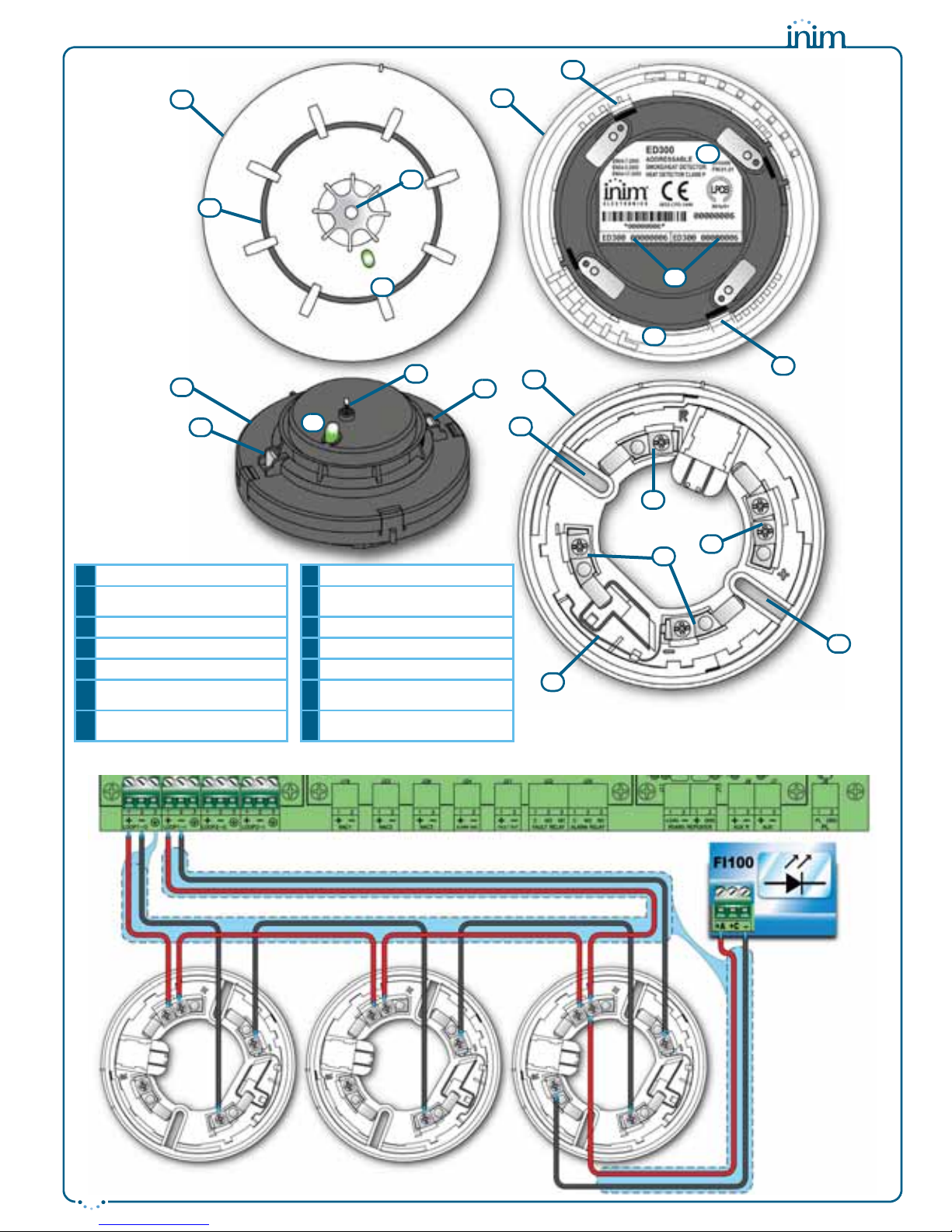
A
Detector
H
Cover removing hooks
B
Base
I
Optical chambre removing
hooks
C
Red/yellow/green LED
L
“+” terminal
D
Optical chamber
M
“-” terminals
E
Thermal probe
N
“R” terminal
F
Technical specifications/
serial-number sticker
O
Short-circuit reed
G
Removable serial-number
stickers
P
Screw locations
A
C
E
F
I
L
M
N
O
B
D
A
C
H
H
D
E
C
P
P
G
I
Page 4

4
Enea
Once the base is located properly in its placement, place the detector
unit onto the base and, with minimum force, turn it clockwise until
notch “A” aligns with notch “B” (in order to attach the detector to the
base); turn it still further until notch “A” aligns with notch “C” (in
order to allow the base to engage with the detector contacts).
When installation of all the loop devices is complete, proceed with
the addressing phase. Refer to the respective section in the control
panel installation and programming manual.
Testing and maintenance
After installation and during periodic maintenance inspections, you
must carry out the following operations on each detector:
•
Check the LED
; if the yellow LED is On solid, the detector is in fault
status. The detector may simply require cleaning, however, if after
cleaning, this condition persists, you should remove the faulty detector
and replace it with a new one. The control panel will allow you to trace
and identify the cause of the fault.
•
Optical smoke detector test
; smoke detectors should be tested
immediately after installation and periodically during maintenance
inspections in accordance with the established standard regulations and
codes in force. To test smoke detectors, use an approved test aerosol
strictly in accordance with the accompanying instructions.
Ensure that the smoke inlet ports to the smoke detection chamber are not
blocked. Check the contamination level of the smoke detection chamber
via the control panel. If the contamination level is high (above 50%),
detach the detector from its mounting base, open the device and, using a
small, soft-bristle brush or hand-held vacuum cleaner remove all dust
particles from inside and around the smoke detection chamber and free
the protection net from all contaminants.
•
Heat detector test
; using a suitable device (e.g. hairdryer), create heat in the vicinity of the detector, then work through
the steps described in the device instruction sheet. During each periodic maintenance inspection, ensure that the heat
element is intact and that is not obstructed by dust or paint. If it is, using a small, soft-bristle brush or hand-held vacuum
cleaner remove all contaminants.
Operating mode
The three-colour LED (360° viewing) indicates the detector status, as follows:
• Green blinking at 15-second intervals; the detector is in standby status (i.e. operating properly).
• Green On solid; the LED has been activated manually from the control panel. This operation allows easy identification of
the detector.
• Yellow On solid; the detector is in fault status or has detected a short-circuit in the succeeding wiring section (short-circuit
isolator open). Further details regarding the fault can be obtained through the control panel.
• Red On solid; the detector is in alarm status. Further details regarding the alarm can be obtained through the control panel.
Each detector has an output (terminal “R”), for the connection of an alarm repeater LED. This LED will activate in
accordance with programming carried out via control panel. The detector is also capable of discerning whether its
repeater LED has been connected. This function provides indications (on the control panel) regarding the
detectors with connected LEDs, and also fault signals in the event of disconnection.
Using the EITK-DRV driver
The EITK-DRV driver allows you to change the operating parameters of the detectors, check the contamination
level of the smoke chambers and also obtain accurate diagnostic data. It can operate through the USB port of a
computer furnished with the relative software programme, or can function autonomously by way of the battery
housed inside.
Each detector is capable of retaining memory (smoke and/or temperature depending on the model) of the 5
minutes prior to an alarm. Therefore, if an alarm occurs, it will be possible to obtain information regarding the
onset of the fire by simply connecting the EITK-DRV driver to the detection line.
For further information and details regarding use of the EITK-DRV driver, refer to the respective handbook.
Warnings and limitations
Enea series detectors must be used exclusively with fully compliant, compatible control panels. Detectors may
not provide timely warning of fire if coverage is limited by large obstructions (pillars, large machinery, etc.).
When installing or working on a fire detection system, always refer to and comply with the established standard
regulations and codes. Appropriate fire-risk assessment should be undertaken to determine the type of detectors
required and their placements.
A
B
C
INIM Electronics reserves the right to change the
technical specifications of this product without
prior notice.
INIM Electronics s.r.l.
via Fosso Antico, Centobuchi
63033, Monteprandone, (AP) Italy
Tel. +39 0735 70 50 07
Fax + 39 0735 70 49 12
www.inim.biz [email protected]
 Loading...