

EnduroSat S-BAND / UHF TRANSCEIVER User Manual

USER MANUAL
Communication Module

S-BAND / UHF TRANSCEIVER – USER MANUAL
ENDUROSAT
2
1 Change log ........................................................................................................................ 3
2 Acronyms list ..................................................................................................................... 4
3 System Overview ............................................................................................................... 5
4 Highlighted Features .......................................................................................................... 6
4.1 Transceiver S-Band ................................................................................................................. 6
4.2 Transceiver UHF ...................................................................................................................... 6
5 System Description ............................................................................................................ 7
6 Electrical Characteristic ..................................................................................................... 9
6.1 Transceiver S-Band ................................................................................................................. 9
6.2 Transceiver UHF ...................................................................................................................... 9
7 RF Characteristics ........................................................................................................... 10
7.1 Transceiver S-Band ............................................................................................................... 10
7.2 Transceiver UHF .................................................................................................................... 14
8 Connector Pinout ............................................................................................................. 16
8.1 Connectors Location ............................................................................................................. 16
8.2 H1 - Stack Connector ............................................................................................................ 17
8.3 H2 - Stack Connector ............................................................................................................ 17
9 Mechanical Drawing ........................................................................................................ 19
10 Envinronmental And Mechanical Testing ........................................................................ 20
11 Materials And Processes ................................................................................................. 20
12 Handling And Storage ..................................................................................................... 20
13 Warnings .......................................................................................................................... 21
S-BAND / UHF TRANSCEIVER – USER MANUAL
ENDUROSAT
3
S-BAND / UHF TRANSCEIVER
USER MANUAL
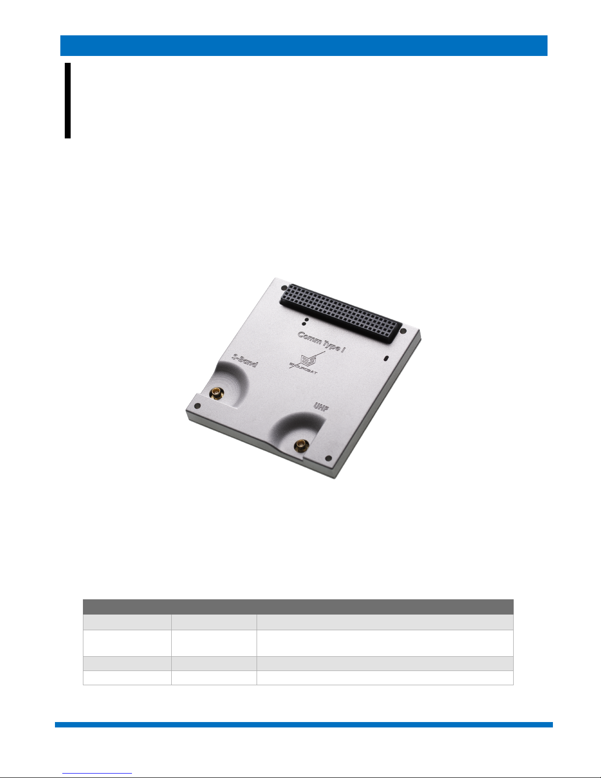
This user manual is specially designed to detail the EnduroSat S-Band / UHF Communication module
functions and features.
Please read this manual before unpacking and using the module to ensure safe and proper use.
Figure 1 - Communication module
1 CHANGE LOG
Date
Version
Note
27/06/2016
Rev 1
15/07/2016
Rev 1.2
Minor text and format changes. Updated pinout
connectors, weight, block diagrams.
04/11/2016
Rev 1.3
Electrical characteristics paragraph
18/11/2016
Rev 1.4
Corrections sensitivity, power consumptions

S-BAND / UHF TRANSCEIVER – USER MANUAL
ENDUROSAT
4
2 ACRONYMS LIST
BER
Bit Error Rate
BPF
Berkeley Packet Filter
ECSS
European Cooperation Space Standardization
EMI
Electromagnetic interference
ESA
European Space Agency
ESD
Electrostatic Discharge
GEVS
General Environmental Verification Standard.
GFSK
Gaussian Frequency Shift Keying
GND
Ground
I2C
Inter-Integrated Circuit
LDO
Low-DropOut
LNA
Low-Noise Amplifier
MCU
Microcontroller Unit
MCX
Micro Coaxial
PCB
Printed Circuit Board
PER
Packet Error Ratio
RF
Radio Frequency
SPI
Serial Peripheral Interface
UART
Universal Asynchronous Receiver/Transmitter
UHF
Ultra-High Frequency
USART
Universal Synchronous Asynchronous Receiver Transmitter
USB
Universal Serial Bus

S-BAND / UHF TRANSCEIVER – USER MANUAL
ENDUROSAT
5
3 SYSTEM OVERVIEW
This S-Band / UHF communication module features dual frequency communication via totally
independent half-duplex transceivers on a single PCB. Both bands are in the amateur range and can
be configured in the whole allocated spectrum – 430-440 MHz and 2400-2480 MHz for the UHF and
S-Band respectively. Furthermore, they feature configurable data rates, which can be programmed
on-orbit – 2 for the UHF and 4 for the S-Band.
The output power can also be tuned in order to maximize the power budget depending on orbit
altitude, ground station and desired minimum elevation angle for communication. The primary
designation for the UHF is telemetry and telecommand while the S-Band is more suitable for payload
data downlink at higher bit rate. Nevertheless, both transceivers can be used for both downlink and
uplink and provide redundancy to each other. There are two separate microcontrollers that manage
the two transceivers thus enabling them to work independently and even simultaneously. Reed-
Solomon encoding of the data increases the reliability of the link. The device is fully encapsulated in
an aluminum shell that takes care of heat dissipation from the power amplifiers and significantly
reduces the EMI.

S-BAND / UHF TRANSCEIVER – USER MANUAL
ENDUROSAT
6
4 HIGHLIGHTED FEATURES
4.1 Transceiver S-Band
• Frequency range: 2400-2480 MHz;
• Typical transmit power: 2 W (33 dBm);
• Power amplifier efficiency: >40%;
• Power supply: 5 V +/- 0.25 V;
• Typical current consumption: up to 1.35 A;
• Frequency stability: +/- 10 ppm;
• Data rate: 250 kbps – 2 Mbps;
• Sensitivity: -94 to -86 dBm;
• Interfaces: SPI (SLAVE).
4.2 Transceiver UHF
• Frequency range: 430-440 MHz;
• Maximum transmit power: 1.5 W;
• Power amplifier efficiency: >70%;
• Power supply: 3.2 – 3.4 V;
• Typical Current consumption: up to 0.82 A;
• Frequency stability: +/- 2.5 ppm;
• Data rate in the air: 2000 – 12000 bps;
• Sensitivity: -113 to -121 dBm;
• Interfaces: UART @ 9600bps / I2C (optional);
• Type: Half-duplex;
Weight
114g
External dimensions
90.2x95.9x25.2mm
S-BAND / UHF TRANSCEIVER – USER MANUAL
ENDUROSAT
7
5 SYSTEM DESCRIPTION
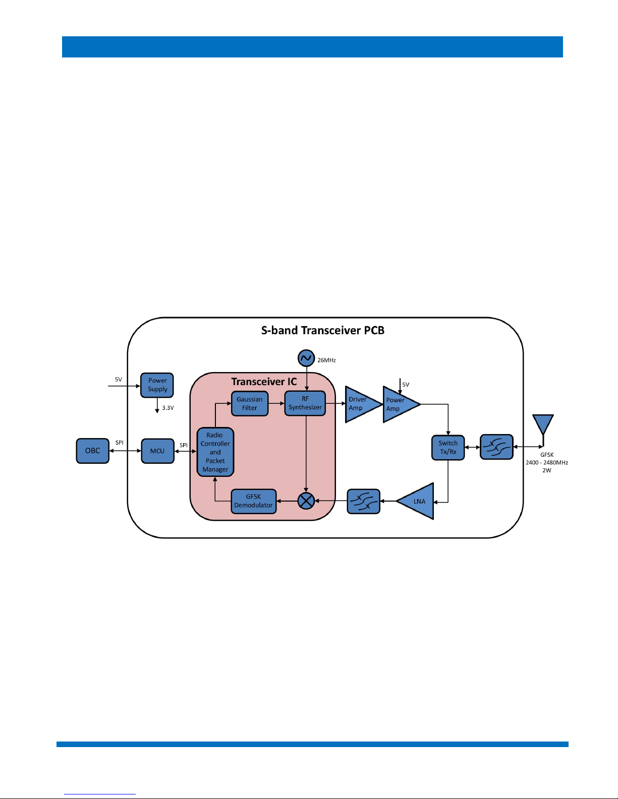
The S-band transceiver works in the frequency range 2400 – 2480 MHz with GFSK modulation. In
the core of this S-band transceiver there is a high performance IC which is a zero-IF transceiver. It is
responsible for the output signal forming and also down converting and demodulating of the input
signal. It contains radio controller and packet manager which makes it very flexible. For its integrated
frequency synthesizer and system timing it uses a 26 MHz reference signal. In the Tx signal chain
there is a RF driver amplifier followed by a PA which boosts the output signal up to 2 W. In the Rx
signal chain there is a LNA followed by BPF. There is also а Tx/Rx switch since the device is half-
duplex. The communication with the OBC (or payload) is accomplished by SPI interface of the MCU.
The supply voltage to the transceiver must be 5V ±0.25V and is directly connected to the PA. There
is a LDO, which reduces the voltage for the rest of the schematic to 3.3 V. The connector used is
PC-104 suitable for stackable configurations. The connector for the antenna is MCX.
Figure 2 - Block Diagram of the S-Band transceiver
 Loading...