

Page 1
SM645-1P & SM645-2P
TM
Voltage:
220
Phase:
1
Cycles:
50/60
Variable Speed
to 4500 RPM
SM645-2P
TM
Voltage:
110
Phase:
1
Cycles:
50/60
Variable Speed
to 4500 RPM
SM645-1P
SERVO MOTOR WITH POSITIONER
ENGLISH USER INSTRUCTIONS & PARTS LISTING
TM
SM645-1P ENDURO™ PRO
Copyright © 2011 Enduro™ Servo Motor
SM645-2P ENDURO™ PRO
www.endurosaves.com
INSTRUCTIONS - PAGE 2 >
PARTS LISTING - PAGE 13 >
Page 2

2 - ENGLISH
SM645-1P & SM645-2P ENDURO™ PRO SERVO MOTOR WITH
POSITIONER USER INSTRUCTIONS
Congratulations!
You have purchased the Enduro™ Pro SM600 series motor that pays for itself with a remarkable 60%
to 80% energy savings compared to clutch motors. With the high and rising cost of electricity, you just
can’t afford to run a clutch motor any longer. The power and dependability of the brushless Enduro™
Pro SM600 series is adequate for light duty sewing.
Please read these instructions carefully before installation, operation or maintenance.
General Introduction
The Enduro™ Pro SM600 Series Servo Motor is designed to meet almost all basic light duty requirements
of various commercial sewing machines. It utilizes extremely powerful rare-earth Neodymium permanent
magnets. The motor produces almost no noise, saves energy and is brushless, speed adjustable and
durable. It provides a high starting torque even at low speed or from a complete stop.
By using a modern technologically advanced microprocessor, Hall sensor and Pulse-Width Modulation
technology, the Enduro™ Pro SM600 series can be set to rotate at different maximum speeds, in either
normal or reverse directions, and can start with different accelerating speeds. It will stop automatically with
any interruption such as in-line voltage, electrical surge, radio frequency interference or overloading. It
is fully protected by the software and will give error messages indicating which problem is encountered.
It even works well in environments with an unstable electrical power supply.
CAUTION
1. Remove your foot from the pedal when turning the power ON.
2. Turn the power switch OFF before replacing or threading the needle.
3. Turn the power switch OFF when leaving the machine.
4. When performing maintenance on the sewing machine, turn the motor power switch to
the OFF position. Remove the power cord from the back of the motor to completely
disable all power to the sewing machine.
5. Always ground the grounding wire.
6. Always turn off the power switch before connecting or disconnecting each connector.
7. To avoid an accident, do not alter this motor and control box.
Warranty
This product is covered with a 1 year limited warranty. If the motor fails to perform its designed function
due to manufacturer’s defects, contact the place you purchased it from for repair or replacement.
This warranty does not cover defects due to dropping, power surge, spikes or misuse.
Installation
Put the mounting bracket of the motor upwards to the bottom of the tabletop and x the motor to the
tabletop with the bolts provided. Connect the treadle rod with the connecting rod joint. Install the female
plug of the cable from the switch box into the power inlet socket in the back of the motor box.
www.endurosaves.com
Page 3
Wiring
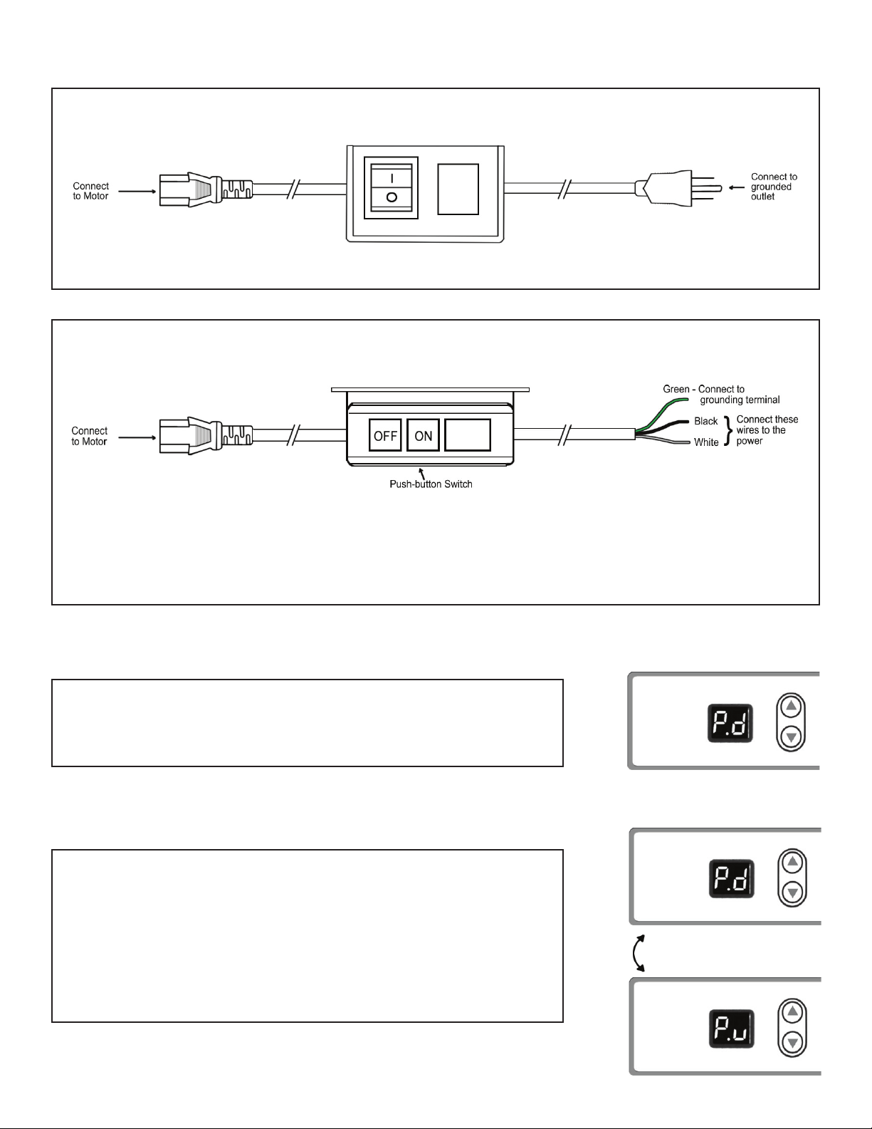
For 110 volt single phase motor follow the diagram below:
For 220 volt single phase motor follow the diagram below:
ENGLISH - 3
Note: When wiring the motor to the power source, connect both the black and white wires to
achieve 220 Volts (green to ground). If you are in an area (China / Europe) that supplies 220 Volts
from a single lead, then connect the power source to the black wire. The white wire will then be the
neutral and the green wire will be the ground.
Setting Up
Turn on the power switch located on the switchbox. The display
will show "P.d", which means the motor is in "ready" status,
ready to work or be set.
default "ready" status
Ready Status
"P.d" is the factory default "ready" status setting and means the
needle position setting is POSITION DOWN. "P.d" is "ready"
status while default setting is not changed.
default "ready" status
Once the needle position setting is changed to "P.u" (which
means the needle position setting is POSITION UP), then "P.u"
becomes the "ready" status.
www.endurosaves.com
Either "P.d" or "P.u" will indicate
"ready" status, depending on
how the needle position is set.
alternate "ready" status
Page 4
4 - ENGLISH
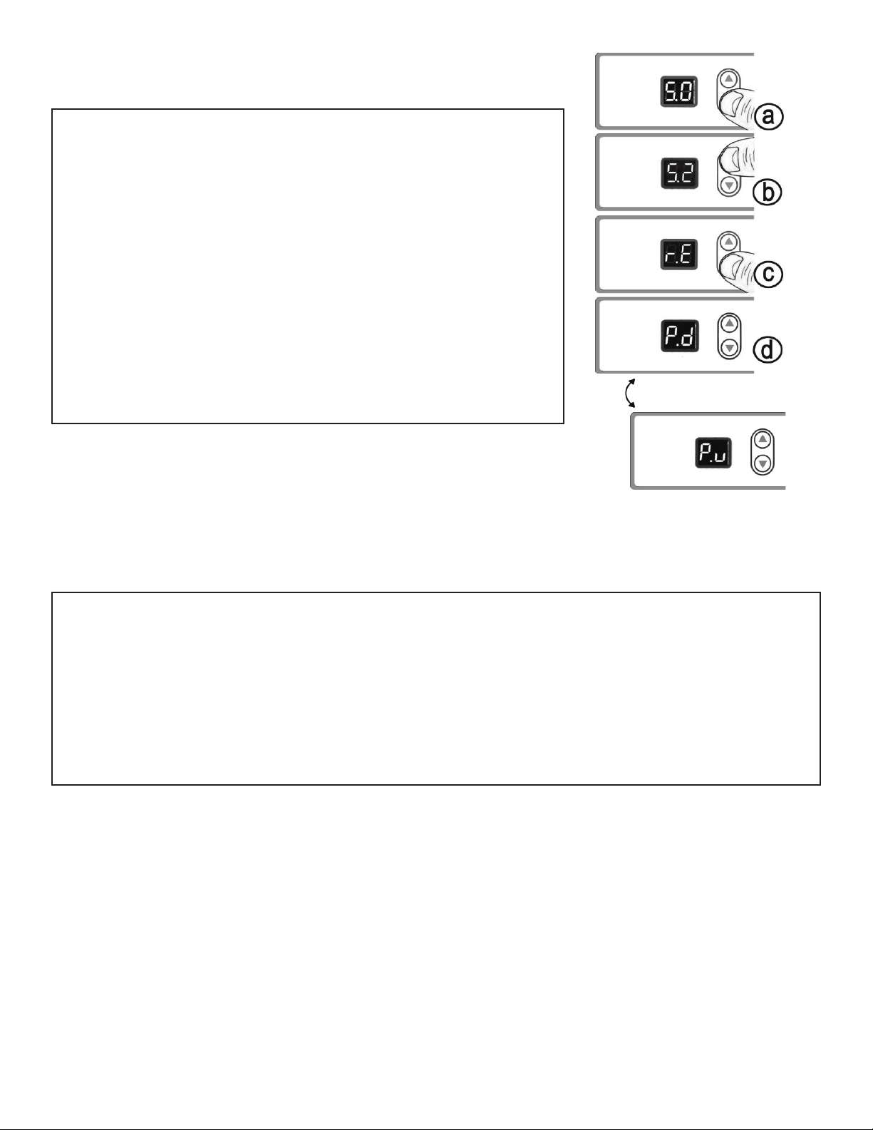
Motor Rotating Direction Setting
Setting up Number 2
a. Keep "▼" button pressed for several seconds, until LED
display indicates "S.0".
b. Press
"▲" button 2 times to indicate "S.2", which means
"Setting up No. 2".
c. Press "▼" button and LED will indicate "r.E" or "r.P"
Press "▼/▲" to switch between E and P, to meet the
requirement of the sewing machine.
"E" means the motor will run in reversed direction.
"P" means the motor will run in normal direction.
d. Setting will be automatically saved 5 seconds after no buttons
are pressed. The motor returns to "ready" status.
Slow Starting Speed
Setting up Number 1
default "ready" status
Either "P.d" or "P.u" will indicate
"ready" status, depending on
how the needle position is set.
alternate "ready" status
1. The "slow period time" = 128 milliseconds
* X, (slow starting setting), X = 0~9 (as setting up in
the motor).
2. Example: The treadle is depressed approximately half way down producing a motor speed
of about 2,000 RPM and if the Slow Starting is set at 9, then the time from 0 to 2000RPM is
theoretically 128 milliseconds X 9 = 1152 milliseconds, plus the electrical-mechanical delay
which is about 0.8 seconds.
3. If the Slow Starting is set at 0, the "real starting time" and time from 0-2000RPM is about 0.8
seconds, which is due to the unavoidable electrical-mechanical delay.
www.endurosaves.com
Page 5

Option A - Setting Slow Starting Speed via Motor Control
a. Keep "▼" button pressed for several seconds, until LED
display indicates "S.0".
ENGLISH - 5
b. Press
"▲" button 1 time to indicate "S.1", which means
"Setting up No. 1".
c. Press "▼" button and LED indicates "L.X" (X is 0-9),
Press "▼/▲" to adjust from 0 to 9 according to your own
application. 0 means the quickest. 9 means the slowest. The
manufacturer’s default setting is 0.
d. Setting will be automatically saved 5 seconds after no buttons
are pressed. The motor returns to "ready" status.
Option B - Setting Slow Starting Speed Manually
default "ready" status
Either "P.d" or "P.u" will indicate
"ready" status, depending on
how the needle position is set.
alternate "ready" status
The larger the gap between the slow start shaft and the treadle bar the faster the initial
starting speed.
1. Notice the small gap
between the slow start shaft
and the treadle bar.
4. Turn both the screw nuts to
make them move upward.
2. Unscrew the lower nut
while holding the upper one to
loosen them from each other.
5. Tighten the two nuts against
each other.
www.endurosaves.com
3. Press the treadle bar down,
to force the shaft to move
downward.
6. The larger gap the faster the
initial starting speed.
Page 6

6 ENGLISH
Maximum Speed Setting
Setting up Number 3
a. Keep "▼" button pressed for several seconds, until LED
indicates show "S.0".
b. Press "▲" button 3 times to indicate "S.3", which means
"Setting up No. 3".
c. Then press "▼" button and LED indicates "XX"(XX is 1-45),
which means the highest motor speed in RPM. ("45" means
4500rpm, and "10" means 1000rpm)
Press "▼/
▲" to adjust the Maximum Speed from 100rpm to
4500rpm. The manufacturer’s default setting is 3800rpm.
d. Setting will be automatically saved 5 seconds after no buttons
are pressed. The motor returns to "ready" status.
default "ready" status
Either "P.d" or "P.u" will indicate
"ready" status, depending on
how the needle position is set.
alternate "ready" status
STITCHES PER MINUTE AT 1000 RPM MOTOR SPEED
MOTOR
PULLEY
DIAMETER
MM / INCHES 55 = 2-1/8 60 = 2-3/8 65 = 2-5/8 80 = 3-1/4 100 = 4 120 = 4-3/4 140 = 5-5/8 160 = 6-3/8
50 = 2 925 850 775 625 500 425 350 315
60 = 2-3/8 1100 1000 925 750 600 500 425 375
75 = 3 1375 1250 1150 935 750 625 525 475
80 = 3-1/4 1500 1350 1250 1000 800 675 575 500
90 = 3-5/8 1625 1500 1400 1125 900 750 650 565
100 = 4 1750 1650 1550 1250 1000 850 715 625
110 = 4-3/8* 2000 1850 1700 1375 1100 925 775 685
120 = 4-3/4* 2250 2050 1850 1500 1200 1000 850 735
130 = 5-1/8* 2500 2250 2000 1625 1300 1075 925 775
* Requires special pulley cover SM636 and special pulley bracket SM638.
SEWING MACHINE HANDWHEEL PULLEY SIZE
Changing the Pulley
Remove pulley cover and pulley. Securely tighten the new chosen pulley.
Caution – Incomplete tightening may cause malfunctions. Also, be sure the pulley cover is correctly
positioned to avoid rubbing against the pulley or the V-belt.
www.endurosaves.com
Page 7

Installation of Positioner on SM645-1P & SM645-2P
ENGLISH - 7
1. Be sure the female power cord is disconnected from the power inlet socket.
2. Remove
with the adapter screw (supplied).
3. Install
the positioner sensor rod into the groove on the sensor and lock the rod onto the machine with
the nut (supplied).
4. Connect the sensor signal wire plug to the socket on the rear panel of the motor box.
5. Plug the power cord from the switch box into the power input socket on the rear panel of the
motor.
6. Power ON the motor.
7.
Check the position of the needle with the motor working.
the needle is incorrect, loosen the set screws on the sensor and move the belt pulley until the
8. If
sensor light shows for correct needle position by illuminating.
9. WARNING: DO NOT MAKE THE SENSOR RUN DURING THIS POSITIONER SETUP
PROCESS.
10. Make sure positioner is correct. Then tighten the two (2) set of screws on the sensor.
the screw on the machine pulley. Install the sensor adapter (supplied) onto the pulley
the positioner sensor onto the sensor adapter and fasten with the two set screws. Install
www.endurosaves.com
Page 8

8 - ENGLISH
Needle Position Setting
a. At any time when the motor is on but not running, press the
up button "▲".
If the LED indicates: "P.u" it means the needle position setting
is POSITION UP when the sewing machine is stopped.
If the
LED indicates: "P.d" It means the needle position setting
alternate "ready" status
Either "P.d" or "P.u" will indicate
"ready status, depending on how
the needle position is set.
is POSITION DOWN when the sewing machine is stopped.
This is the default factory setting.
b. Press "▼/ ▲" to switch the setting of the needle position
between either UP or DOWN.
default "ready" status
When positioner sensor is set correctly to the UP position and you stop sewing, the needle will stop
at the UP position. If you then heel the treadle, the motor will rotate to put the needle in the DOWN
position.
When the position sensor is set to the DOWN position and you stop sewing, the needle will stop at the
DOWN position. If you then heel the treadle, the motor will rotate to put the needle in the UP position.
Error Messages and Trouble Shooting
When an error message appears on the display the motor will stop automatically to protect the electronics
of the motor and most importantly, to protect the motor circuit board.
If an error message occurs be sure to repeat the action that caused the error message. Many times if
you reactivate the treadle and start the motor again, the error message will clear indicating this was a
False error message requiring no further action.
There are two types of error messages:
1) False error messages
2)
True error messages if the error is repeated.
False errors messages are common in areas where the electricity being supplied is unstable due
to uctuations, interference and spikes in electrical power supply to the motor. If these False error
messages happen quite often it is recommended to contact a local electrician to see if the power
supplied to the motor can be ltered. Doing so will eliminate False error messages.
True error messages do occur occasionally indicating a problem with an electrical component, the
motor circuit board and on a very rare occasion, a faulty motor.
www.endurosaves.com
Page 9

9 - ENGLISH
E1: Motor Control Error
1. Most E1 error messages occur because of unstable power being supplied to the motor.
• Release
the motor. If the E1 error message no longer appears this was a False error due to unstable
power.
2. If the E1 error message continues to appear:
• Replace the motor circuit board with a new motor circuit board. Once the motor circuit board
is replaced the E1 error message should no longer display.
3. If
the E1 error message still appears after changing the motor circuit board, this is a very rare
occurrence due to a faulty motor.
E2: Motor Phase Signal Error (Hall Sensor Error)
the pedal when the E1 error message occurs, then push down again to activate
1. It is possible to receive an E2 error message from unstable power which means it is a False
error and the problem should resolve on its own.
2. Check
Pin connector / socket), to make sure the 5 wires are connected to the board properly.
3. If the E2 error message continues to appear the motor is faulty and will not function properly.
E3: Motor Protected Against Over Current
1. It is possible to receive an E3 error message from unstable power which means it is a False
error and the problem should resolve on its own.
2. Usually
by a heavy load when sewing. When this happens, more and more electrical current is driven to
the motor until the electrical current exceeds the amount allowed by the motor. If this happens,
the E3 error message is displayed and the motor is stopped to protect the motor from overload
or burn out.
the Hall sensor signal connector and socket (HER indicated) on the circuit board (Five
, the E3 error message occurs when the motor rotation is stuck by something or blocked
Remove the obstruction that is prohibiting rotation and the E3 error message should no longer
•
display.
3. If nothing is blocking the sewing process and the motor can turn freely and the E3 error message
is displayed, it is likely a faulty motor circuit board.
• Replace the motor circuit board and the E3 error message should no longer display.
www.endurosaves.com
Page 10

10 - ENGLISH
E4: Circuit Board Error in Memory Reading and Writing
1. It is possible to receive an E4 error message from unstable power which means it is a False
error and the problem should resolve on its own.
2. If the E4 error message continues to display it indicates a faulty motor circuit board.
• Replace the motor circuit board and the E4 error message should no longer display.
E5: Display Module and Control Module Communications Error
1. It is possible to receive an E5 error message from unstable power which means it is a False
error and the problem should resolve on its own.
2. E5 error message indicates a faulty LED display
• Check connections on the LED display module to be sure it is securely fastened to the motor
circuit board. If the E5 error message no longer displays, then the connection to the motor circuit
board was loose.
• If the E5 error message continues to appear then replace the LED display module (No. SM627
for 2 digit readout) and the E5 error message should no longer display.
3. If the E5 error message continues to appear it indicates a faulty motor circuit board.
• Replace the motor circuit board and the E5 error message should no longer display.
.
www.endurosaves.com
Page 11

11 - ENGLISH
E6: Pedal Position Sensor Error
1. It is possible to receive an E6 error message from unstable power which means it is a False
error and the problem should resolve on its own.
2. While
abnormal, it is possible to get the E6 error message. This is most common because of a faulty
treadle sensor, misalignment of the sensor versus blocker, or improper operation such as the
treadle is already pressed down before the motor is turned on.
•
of the blocker if necessary (see diagram of Proper Replacement of Treadle Sensor).
• Check the snap on connector of the treadle sensor and be sure it is securely attached. If the
E6 error message no longer appears the connector was loose.
• If the E6 error message continues to appear, then replace the treadle sensor (Dual channel
sensor for positioner motors No. SM76), and the E6 error message should no longer display.
• When replacing the treadle sensor be sure it is properly aligned. If the treadle sensor is not
aligned properly you may have a problem with the motor continuing to run after releasing the
treadle (see diagram of Proper Replacement of Treadle Sensor).
3. If
circuit board is likely faulty.
the motor is on and the pedal position signal received by the motor circuit board is
Check
after replacing the treadle sensor and the E6 error message continues to appear the motor
the alignment of the sensor versus blocker on the treadle sensor plate. Adjust the position
• Replace the motor circuit board and the E6 error message should no longer display.
www.endurosaves.com
Page 12

ENGLISH - 12
Treadle Sensor Installation Description with Diagrams (Proper Replacement of Treadle Sensor)
2
1
1. Remove the 4 screws on the treadle sensor
plate.
3
3. Check the relative position of the sensor
and light blocker. If the light blocker is in a
position that has blocked the light when the
treadle is not pushed down, the motor will
rotate. Adjust the blocker position if necessary
by loosening the screw and tightening it again.
2. Check the channel sensor. It should have
a red light when the cable is connected to the
motor circuit board and the motor is powered
on. Check the cable connection if there is no
red light.
4. Change the sensor if necessary by
unscrewing and reinstalling the two screws.
Then connect the cable to the motor circuit
board. The red light should appear when the
motor is powered on indicating it is working.
www.endurosaves.com
Page 13

SM6451P & SM645-2P PARTS LISTING
ENGLISH - 13
No. Fig. Description
SM76 A Sensor only with screws (dual channel for motors with positioner)
SM604 B Treadle Sensor Plate Assembly complete with 4 screws (dual channel for motors with positioner) (431U)
SM77 C Replacement positioner sensor kit complete
SM618 D Complete wire harness for 110 volt models, fused (PF Gray)
SM619 E Fuse only for 110 volt wire harness
SM620 F Fuse cap for 110 volt wire harness
SM621 G On/Off toggle replacement switch only
SM78 H Complete horizontal wire harness for 220 volt models (431C)
SM645 I SM645-1P label
SM646 I SM645-2P label
SM625 J SM600 Pro series control box cover with 4 screws (431U Matte)
SM627 K 2 Digit LED display with screws
SM641 L SM645-1P Circuit board with 6 screws
SM642 L SM645-2P Circuit board with 6 screws
SM631 M Motor mounting bracket complete with 4 screws (431U)
SM50 N 50mm pulley with mounting hardware
SM60 N 60mm pulley with mounting hardware
SM75 N 75mm pulley with mounting hardware
SM80 N 80mm pulley with mounting hardware
SM90 N 90mm pulley with mounting hardware
SM100 N 100mm pulley with mounting hardware
SM110 N 110mm pulley with mounting hardware (must be used with SM636 pulley cover and SM638 bracket)
SM120 N 120mm pulley with mounting hardware (must be used with SM636 pulley cover and SM638 bracket)
SM130 N 130mm pulley with mounting hardware (must be used with SM636 pulley cover and SM638 bracket)
SM79 O Pulley cover bracket with screws and washers
SM638 O Special pulley cover bracket with screw and washers (for use with 110mm through 130mm pulley)
SM86 P Pulley cover with screw and washer (431U Matte)
SM636 P Special pulley cover with screw and washer (for use with 110mm through 130mm pulley) (431U Matte)
SM633 Q Rear motor cover panel for SM645-1P & SM645-2P with 6 screws (431U)
SM81 R Power inlet receptacle with wires, terminals and screws complete
SM82 S White positioner socket
SM6451P&SM645-2P 2012-1
www.endurosaves.com
 Loading...