

Page 1
TM
TM
Voltage:
220
Phase:
1
Cycles:
50/60
Variable Speed
to 3800 RPM
SM600-2P
SM600-2P
SERVO MOTOR WITH POSITIONER USER INSTRUCTIONS & PARTS LISTING
INSTRUCTION ET LISTE DES PIÈCES DE L’UTILISATEUR
DU MOTEUR SERVO DE POSITIONNEUR
INSTRUCCIÓN DE USE DE MOTOR SERVO CON
POSICIONADOR & LISTA DE PARTES
SM600-2P ENDURO™ PRO
INSTRUCTIONS DU FRANCAIS - PAGE 10 >
LISTE DES PIECES DU FRANCAIS - PAGE 17 >
INSTRUCCIÓN EN ESPAÑOL - PÁGINA 18 >
Copyright © 2011 Enduro™ Servo Motor
To us Droits Réservé © 2011 Moteur Servo Enduro™
Derecho de autor© 2011 Enduro™ Servo Motor
www.endurosaves.com
LISTA DE PARTES EN ESPAÑOL - PÁGINA 25 >
ENGLISH INSTRUCTIONS - PAGE 2 >
ENGLISH PARTS LISTING - P
AGE 9 >
Page 2

2 - ENGLISH
SM600-2P ENDURO™ PRO SERVO MOTOR WITH POSITIONER
USER INSTRUCTIONS
Congratulations!
You h
energy savings compared to clutch motors. With the high and rising cost of electricity, you just can’t
afford to run a clutch motor any longer. The power and dependability of the brushless Enduro™ Pro
SM600 is adequate for light duty sewing.
Please read these instructions carefully before installation, operation or maintenance.
General Introduction
The Enduro™ Pro SM600 Servo Motor is designed to meet almost all basic light duty requirements of
various commercial sewing machines. It utilizes extremely powerful rare-earth Neodymium permanent
magnets. The motor produces almost no noise, saves energy and is brushless, speed adjustable and
durable. It provides a high starting torque even at low speed or from a complete stop.
ave purchased the Enduro™ Pro SM600 motor that pays for itself with a remarkable 60% to 80%
By using a modern technologically advanced microprocessor, Hall sensor and Pulse-Width Modulation
technology, the Enduro™ Pro SM600 can be set to rotate at different maximum speeds, in either normal
or reverse directions, and can start with different accelerating speeds. It will stop automatically with any
interruption such as in-line voltage, electrical surge, radio frequency interference or overloading. It is
fully protected by the software and will give error messages indicating which problem is encountered. It
even works well in environments with an unstable electrical power supply.
CAUTION
1. Remove your foot from the pedal when turning the power ON.
2. Turn the power switch OFF before replacing or threading the needle.
3. Turn the power OFF when leaving the machine.
4. When performing maintenance on the sewing machine, turn the motor power switch to
the OFF position. Remove the power cord from the back of the motor to completely
disable all power to the sewing machine.
5. Always ground the grounding wire.
6. Always turn off the power switch before connecting or disconnecting each connector.
7. To
Warranty
avoid an accident, do not alter this motor and control box.
This product is covered with a 1 year limited warranty. If the motor fails to perform its designed function
due to manufacturer’s defects, contact the place you purchased it from for repair or replacement.
This warranty does not cover defects due to dropping, power surge, spikes or misuse.
Installation
Put the mounting bracket of the motor upwards to the bottom of the tabletop and fi x the motor to the
tabletop with the bolts provided. Connect the treadle rod with the connecting rod joint. Install the female
plug of the cable from the switch box into the power inlet socket in the back of the motor box.
www
.endurosaves.com
Page 3
ENGLISH - 3
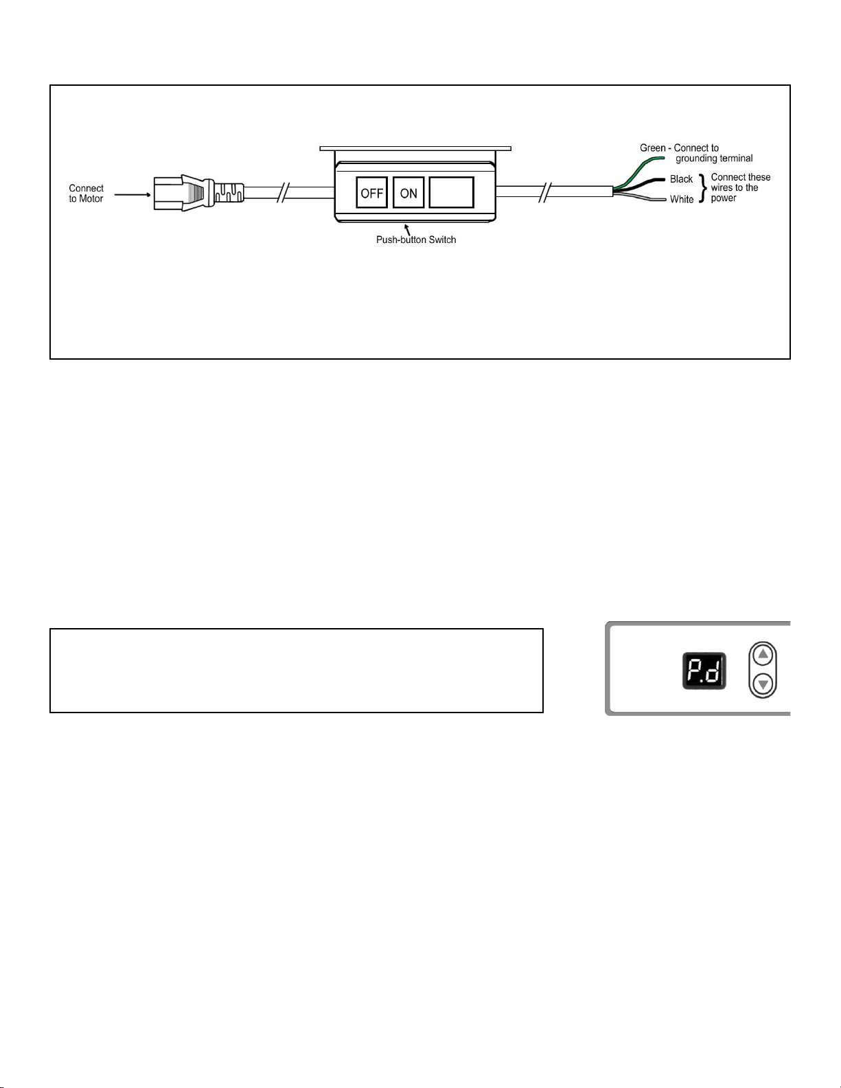
Wiring
For 220 volt single phase motor follow the diagram below:
Note: When wiring the motor to the power source, connect both the black and white wires to
achieve 220 Volts (green to ground). If you are in an area (China / Europe) that supplies 220 Volts
from a single lead, then connect the power source to the black wire. T
he white wire will then be the
neutral and the green wire will be the ground.
Error Message and Trouble Shooting
E2: Motor Phase signal error.
E3: Motor protected against over-current.
E4: Circuit board error.
E5: Display module and control module communication error.
E6: Pedal position sensor error.
E8. Can not fi nd position DOWN.
E9. Can not fi nd position UP.
Setting Up
Turn on the switch located on the switchbox. The display will
show "P. d ", which means the motor is in "ready" status, ready
to work or be set.
default "ready" status
www.endurosaves.com
Page 4

4 - ENGLISH
Ready Status
"
P. d " is the factory default "ready" status setting and means the
needle position setting is POSITION DOWN. "P.d " is "ready"
status while default setting is not changed.
default "ready" status
Once the needle position setting is changed to "P.u " (which
means the needle position setting is POSITION UP), then "P.u "
becomes the "ready" status.
Motor Rotating Direction Setting
Setting up Number 2
a. Keep "▼" button pressed for several seconds, until LED
display indicates "S.0
".
b. Press "▲" button 2 times to indicate "S.2", which means
"Setting up No. 2".
c. Press "▼" button and LED will indicate "r.E" or "r.P"
Press "▼/▲" to switch between E and P, to meet the
requirement of sewing machine.
"E" means the motor will run in reversed direction.
"P" means the motor will run in normal direction.
Either "P. d " or "P. u" will indicate
"ready" status, depending on
how the needle position is set.
alternate "ready" status
d. Setting will be automatically saved 5 seconds after no buttons
are pressed. The motor returns to "ready" status.
www.endurosaves.com
default "ready" status
Either "P. d " or "P.u " will indicate
"ready" status, depending on
how the needle position is set.
alternate "ready" status
Page 5

ENGLISH - 5
Slow Starting Speed
Setting up Number 1
1. The "slow period time" = 128 milliseconds * X, (slow starting setting), X = 0~9 (as setting up in
the motor).
2. Example: The treadle is depressed approximately half way down producing a motor speed
of about 2,000 RPM and if the Slow Starting is set at 9
, then the time from 0 to 2000RPM is
theoretically 128 milliseconds X 9 = 1152 milliseconds, plus the electrical-mechanical delay
which is about 0.8 seconds.
3. If the Slow Starting is set at 0, the "real starting time" and time from 0-2000RPM is about 0.8
seconds, which is due to the unavoidable electrical-mechanical delay only.
a. Keep "▼" button pressed for several seconds, until LED
display indicates "S.0
".
b. Press "▲" button 1 time to indicate "S.1", which means
"Setting up No. 1".
c. Press "▼" button and LED indicates "L.X" (X is 0-9),
Press "▼/▲" to adjust from 0 to 9 according to your own
application. 0 means the quickest. 9 means the slowest. The
manufacturer’s default setting is 0.
d. Setting will be automatically saved 5 seconds after no buttons
are pressed. The motor returns to "ready" status.
default "ready" status
Either "P. d " or "P.u " will indicate
"ready" status, depending on
how the needle position is set.
alternate "ready" status
www.endurosaves.com
Page 6

6 ENGLISH
Maximum Speed Setting
Setting up Number 3
a. Keep "▼" button pressed for several seconds, until LED
indicates show "S.0".
b. Press "▲" button 3 times to indicate "S.3", which means
"Setting up No. 3".
c. Then press "▼" button and LED indicates "XX"(XX is 1-38),
which means the highest motor speed in RPM. ("38" means
3800rpm, and "10" means 1000 rpm)
Press "▼/ ▲" to adjust the Maximum Speed from 100rpm to
3800rpm. The manufacturer’s default setting is 3800rpm.
d. Setting will be automatically saved 5 seconds after no buttons
are pressed. The motor returns to "ready" status.
default "ready" status
Either "P. d " or "P.u " will indicate
"ready" status, depending on
how the needle position is set.
alternate "ready" status
STITCHES PER MINUTE AT 3800 RPM MOTOR SPEED
MOTOR PULLEY
DIAMETER
MM / INCHES
50 = 2 3800 3200 2800 2200 1700 1300
60 = 2-3/8 4500 3800 3300 2700 2000 1500
75 = 3 5700 4800 4200 3400 2500 1900
80 = 3-1/4 6200 5200 4500 3700 2700 2100
90 = 3-5/8 7000 5800 5000 4100 3000 2300
100 = 4 7600 6400 5500 4500 3300 2500
50 = 2 60 = 2-3/8
SEWING MACHINE HANDWHEEL PULLEY SIZE
70 = 2-3/4 85 = 3-3/8 115 = 4-5/8 150 = 6
Changing the Pulley
Remove pulley cover and pulley.
Securely tighten the new chosen pulley.
Caution – Incomplete tightening may cause malfunctions. Also, be sure the pulley cover is correctly
positioned to avoid rubbing against the pulley or the V-belt.
Motor pulley outer
diameter (mm)
=
Normal sewing machine speed
(*) Motor Speed
X
www.endurosaves.com
Sewing machine pulley
diameter
+ 5 mm
Page 7

Installation of Positioner on SM600-2P
ENGLISH - 7
1. Be sure the female power cord is disconnected from the power inlet socket.
2. Remove the screw on the machine pulley. Install the sensor adapter (supplied) onto the pulley
with the adapter screw (supplied).
3. Install the positioner sensor onto the sensor adapter and fasten with the two set screws. Install
the positioner sensor rod into the groove on the sensor and lock the rod onto the machine with
the nut (supplied).
4. Connect the sensor signal wire plug to the socket on the rear panel of the motor box.
5. Plug the power cord from the switch box into the power input socket on the rear panel of the
motor.
6. Power ON the motor.
7. Check the position of the needle with the motor working.
8. If the needle is incorrect, loosen the set screws on the sensor and move the belt pulley until the
sensor light shows for correct needle position by illuminating.
9. WARNING: DO NOT MAKE THE SENSOR RUN DURING THIS POSITIONER SETUP
PROCESS.
10. Make sure positioner is correct. Then tighten the two (2) set of screws on the sensor.
www.endurosaves.com
Page 8

8 - ENGLISH
Needle Position Setting
Setting up Number 4
a. At any time when the motor is on but not running, press the
up button "▲".
If the LED indicates: "P.
u " it means the needle position setting
is POSITION UP.
If the LED indicates: "P. d " It means the needle position setting
is POSITION DOWN. This is the default factory setting.
b. Press "▼/ ▲" to switch the setting of the needle position
between either UP or DOWN.
alternate "ready" status
Either "P. d " or "P. u" will indicate
"ready status, depending on how
the needle position is set.
default "ready" status
When positioner sensor is set correctly to the UP
position and you stop sewing, the needle will stop
at the UP position. If you then heel the treadle, the motor will rotate to put the needle in the DOWN
position.
When the position sensor is set to the DOWN position and you stop sewing, the needle will stop at the
DOWN position. If you then heel the treadle, the motor will rotate to put the needle in the UP position.
www
.endurosaves.com
Page 9

SM600-2P PARTS LISTING
ENGLISH - 9
No. Fig. Description
SM76 A Sensor only with screws (dual channel for motors with positioner)
SM604 B T
SM77 C Replacement positioner sensor kit complete
SM78 D Complete horizontal wire harness for 220 volt models (431C)
SM624 E SM600-2P label
SM625 F SM600 Pro control box cover with 4 screws (431C Matte)
SM627 G 2 Digit LED display with screws
SM630 H SM600-2P Circuit board with 6 screws
SM631 I Motor mounting bracket complete with 4 screws (431C)
SM50 J 50mm pulley with mounting hardware
SM60 J 60mm pulley with mounting hardware
SM75 J 75mm pulley with mounting hardware
SM80 J 80mm pulley with mounting hardware
SM90 J 90mm pulley with mounting hardware
SM100 J 100mm pulley with mounting hardware
SM79 K Pulley cover bracket with screws and washers
SM86 L Pulley cover with screw and washer (431C Matte)
SM633 M Rear motor cover panel SM600-2P with 6 screws (431C)
SM81 N Power inlet receptacle with wires, terminals and screws complete
SM82 O White positioner socket
readle Sensor Plate Assembly complete with 4 screws (dual channel for motors with positioner) (431C)
www.endurosaves.com
SM600-2P 2011-2
 Loading...