

Endurance FB300 Fan Bike User Manual
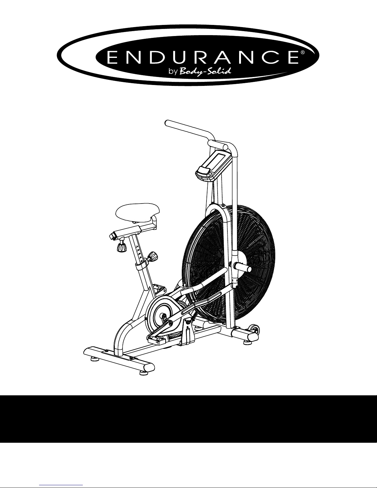
FB300
Endurance® FB300 Fan Bike
User Manual
V. FB300-102716

Table of Contents
Table of Contents......................................................................................................
Introduction................................................................................................................
Important Safety Information..............................................................................
Before You Begin.......................................................................................................
Assembly......................................................................................................................
Setting up FB300......................................................................................................
Dimension........................................................................................................................................
Console Overview.....................................................................................................
Console Operation....................................................................................................
Monitoring Your Heart Rate.................................................................................
Chest Strap Operation.............................................................................................
General Maintenace.................................................................................................
Troubleshooting Guide..........................................................................................
2
3
4
5
6 - 13
14
15
16 - 18
19 - 22
23 - 24
25
26
27
Stretching & Flexibility...........................................................................................
Warm-Up/Cool Down Exercises..........................................................................
Parts & Hardware List..............................................................................................
Exploded Drawing...................................................................................................
Endurance® continually seeks ways to improve the performance, specications and product manuals in order to ensure that only superior
products are released from our factories. Please take the time to carefully read through this manual thoroughly. Instructions contained in
this document are not intended to cover all details or variations possible with Endurance
may be met in conjunction with installation, operation, maintenance or troubleshooting of the equipment. Even though we have prepared
this manual with extreme care, neither the publisher nor the author can accept responsibility for any errors in, or omission from, the informa
tion given. Should additional information be required, or should situations arise that are not covered by this manual, the matter should be
directed to your local Endurance® representative, or the Service Department at Endurance® in Forest Park, Illinois.
Copyright 2012. Endurance®. All rights reserved. Endurance® reserves the right to change design and specications when we feel it will
c
improve the product. Endurance® machines maintain several patented and patent pending features and designs. All rights reserved on
all design patents and utility patents.
equipment, or to cover every contingency that
®
28
29 - 35
36 - 38
40 - 41
-
2

Introduction
Congratulations!!
Thank you for purchasing your new Endurance® Fan Bike.
Using state-of-the-art techniques, robust frame structure and superior ergonomic
design, Endurance® Fan Bike set a new standard for excellence. The Endurance®
Fan Bike can improve your quality of life by keeping you t and healthy, increasing
your energy levels and enhancing your lifestyle.
Endurance® wants to ensure years of quality workouts with your new Fan Bike so
we recommend that you read this manual carefully and thoroughly to fully understand proper use and maintenance of this product. Retain this Owner’s Manual for
future reference.
Please use this Owner’s Manual to make sure that all parts have been included
in your shipment. When ordering parts, you must use the part number and description from this Owner’s Manual. Use only Endurance® replacement parts when
servicing this machine. Failure to do so will void your warranty and could result in
personal injury.
For information about product operation or service, check out the ocial Endurance® website at www.bodysolid.com/Home/Endurance_Cardio or contact an authorized Endurance® dealer or an Endurance® factory-authorized service company or contact Endurance® Customer Tech Support at one of the following:
Toll Free: 1-800-556-3113
Phone: 1-708-427-3555
Fax: 1-708-427-3556
Hours: M-F 8:30-5:00 CST
E-Mail: service@bodysolid.com
Or write to:
Endurance® Service Department
1900 S. Des Plaines Ave.
Forest Park, IL 60130 USA
3

Important Safety Information
Save this Owner’s Manual!
Before beginning any tness program, you should obtain a complete physical
examination from your physician.
When using exercise equipment, you must always take basic precautions, including the
following:
m Read all instructions before using your Endurance® Fan Bike.
These instructions are written to ensure your safety and to protect the unit.
m DO NOT allow children on or near the equipment.
m Use the equipment only for its intended purpose as described in this guide.
m DO NOT use accessory attachments that are not recommended by the
manufacturer. Such attachments might cause injuries and will void your warranty.
m Wear proper exercise clothing and shoes for your workout, no loose clothing.
m DO NOT use cleats, spikes or any other non-athletic shoes.
m DO NOT use this product while barefoot or wearing only socks.
m Use care when getting on or o the unit.
m DO NOT overexert yourself or work to exhaustion. If you experience any pain such
as chest pains, nausea, dizziness, shortness of breath or abnormal symptoms, stop
your workout immediately and consult your physician before continuing.
m Never operate the unit when it has been dropped or damaged.
Return the equipment to a service center for examination and repair.
m Never drop or insert objects into any opening in the equipment.
m Always check the unit for loose components before each use.
m DO NOT turn pedals by hand.
m DO NOT use the equipment outdoors or near water. It is imperative that your
Endurance® Fan Bike is used in a climate controlled environment. If your
Fan Bike has been exposed to colder temperatures or to high moisture
climates, it is strongly recommended that the Fan Bike is brought to room
temperature before use. Failure to use this equipment in a climate controlled
environment may cause premature electronic failure.
m Endurance® recommends that a mat is placed under the unit to protect the oor or
carpet and for easier cleaning.
Endurance® Fan Bikes are designed for your enjoyment. By following these precautions and
using common sense, you can have many safe and pleasurable hours of healthful exercise
with your Endurance® Fan Bike.
4

Before You Begin
The Endurance® FB300 is carefully tested and inspected before shipment. We have
shipped the unit in several pieces that require assembly. Carefully unpack the unit in
a clear area and lay the pieces on the oor near the area where you plan to use the
equipment. Remove the packing material. Do not dispose of the packing material
until assembly is complete and the unit is working properly. Place the unit on a clean
level surface for assembly. Before assembling, the unit should be placed as close as
possible to its nal location. Be careful to assemble all components in the sequence
presented in this guide.
PERSONAL SAFETY DURING ASSEMBLY
m It is strongly recommended that a qualied dealer assemble the equipment.
Assistance is required.
m Before beginning assembly, please take the time to read the instructions
thoroughly.
m Read each step in the assembly instructions and follow the steps in sequence.
Do not skip ahead. If you skip ahead, you may learn later that you have to
disassemble components and that you may have damaged the equipment
which will void the warranty.
m Assemble and operate the Endurance® Fan Bike on a solid, level
surface.
Locate the unit a few feet from the walls or furniture to provide easy access.
AFTER ASSEMBLY
Once the unit is assembled, you should check all functions to ensure correct operation. If you experience problems, rst recheck the assembly instructions to locate
any possible errors made during assembly. If you are unable to correct the problem,
call the dealer from whom you purchased the machine or call Endurance® Customer
Tech Support Hot Line Toll Free at: 1-800-556-3113.
5

Step 1
NOTE:
Some hardware components may be pre-assembled. Be aware of
Nylon lock nuts not fully screw onto bolts, they must be tightened
with a wrench to ensure proper engagement.
1A. Attach Front Stabilizer (M) to Main Frame (A) using:
Two M8x20mm Button Head Cap Screws (#5)
Two M8 Lock Washers (#6)
Two M8 Washers (#7)
1B. Attach Rear Stabilizer (N) to Main Frame (A) using:
Two M8x20mm Button Head Cap Screws (#5)
Two M8 Lock Washers (#6)
Two M8 Washers (#7)
6

步骤一:
1:用内六角盘头螺钉(5)、 弹垫(6)、平垫(7)分别将前底管(M)、后底管(N)锁紧在主
架(A)上.
步骤一:
1:用内六角盘头螺钉(5)、 弹垫(6)、平垫(7)分别将前底管(M)、后底管(N)锁紧在主
架(A)上.
Above shows STEP 1 assembled and completed.
Step 1
7
Step 2
NOTE:
Some hardware components may be pre-assembled. Be aware of
Nylon lock nuts not fully screw onto bolts, they must be tightened
with a wrench to ensure proper engagement.
2A. Attach the Handle Bars (E & F) into the Main Frame (A) by
threading Handle Bar Pivot Shafts (#21). Tighten the
Handle Bar Pivot Shaft (#21) by Inserting the Allen Wrench into
the hole of the Foot Peg and turn clockwise.
2B. Attach the Handle Bars (E & F) to the Linkages (H) using:
Two M8x45mm Shoulder Bolts (#14)
Two M8 Hex Nut (#15)
Two M8 Nylon Lock Nut (#17)
2C. Insert Seat(#3) onto the knurled section of the Horizontal
Seatpost (D) and tighten the clamp of the Seat (#3).
2D. Put Washer (#28) onto the M8x15mm Button Head Cap Screw
(#27) and thread the screw (#27) into the end of the Horizontal
Seatpost (D).
8

步骤二:
1:先用脚踏杆轴(21)将左摆杆(E)、右摆杆(F)含在主架(A)上的两侧,(先不要锁紧);
2:用轴肩螺栓(14)、六角薄螺母(15)、尼龙螺母(17)将左摆杆(E)、右摆杆(F)与连杆(H)连接锁
紧,并将脚踏杆轴(21)锁紧。
3:用内六角圆柱头螺钉(27)、平垫(28)将鞍座(3)锁紧在鞍座横管(D)上.
步骤二:
1:先用脚踏杆轴(21)将左摆杆(E)、右摆杆(F)含在主架(A)上的两侧,(先不要锁紧);
2:用轴肩螺栓(14)、六角薄螺母(15)、尼龙螺母(17)将左摆杆(E)、右摆杆(F)与连杆(H)连接锁
紧,并将脚踏杆轴(21)锁紧。
3:用内六角圆柱头螺钉(27)、平垫(28)将鞍座(3)锁紧在鞍座横管(D)上.
Above shows STEP 2 assembled and completed.
Step 2
9

Step 3
NOTE:
Some hardware components may be pre-assembled. Be aware of
Nylon lock nuts not fully screw onto bolts, they must be tightened
with a wrench to ensure proper engagement.
3A. Screw (counterclockwise) Left Pedal (P) onto Left Crank (#1).
3B. Screw (clockwise) Right Pedal (Q) onto Right Crank (#2).
Note: Make sure the Pedals are wrench tightened.
10
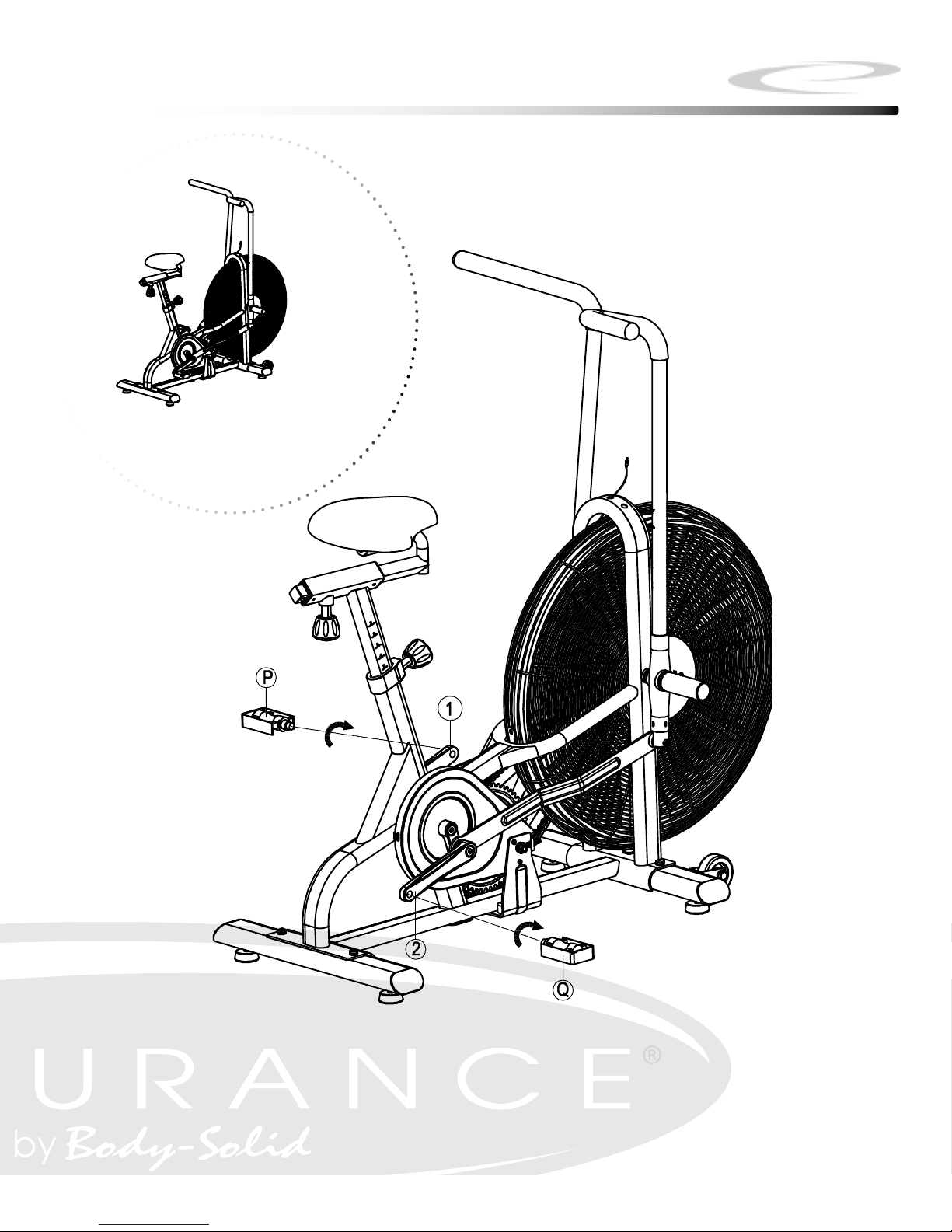
Above shows STEP 3 assembled and completed.
步骤三:
将左脚蹬(P)、右脚蹬(Q)分别锁紧在左曲柄 (1)、右曲柄(2)上;注:左脚蹬 (P)应逆时针锁
紧 右脚蹬(Q)应顺时针锁紧。 按如下图箭头所指的方向,在运动过程中时刻保持 左脚蹬(P)、右
脚蹬(Q)在旋紧状态,否则将会使 左脚蹬(P)、右脚蹬(Q)的牙损坏。
Step 3
11

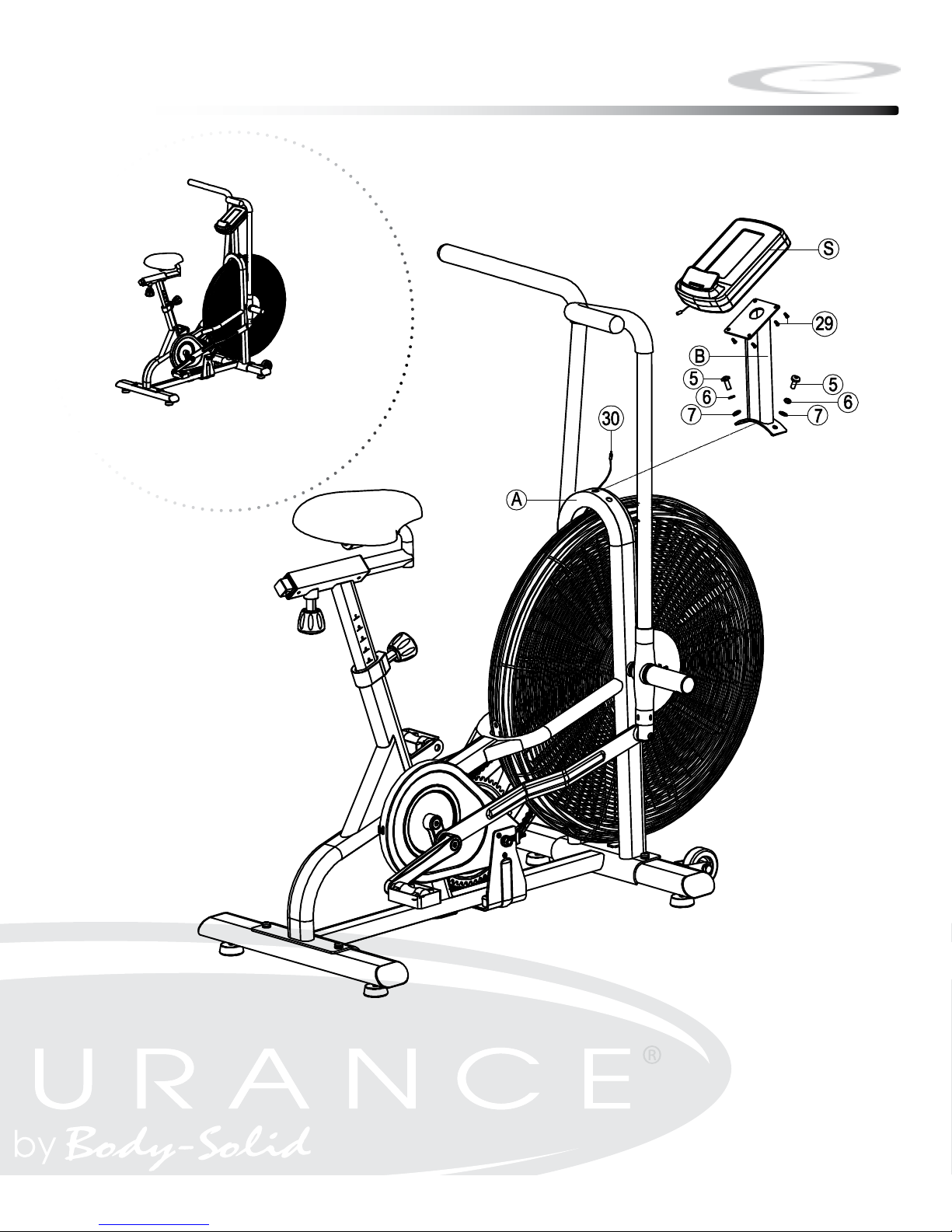
Step 4
NOTE:
Some hardware components may be pre-assembled. Be aware of
Nylon lock nuts not fully screw onto bolts, they must be tightened
with a wrench to ensure proper engagement.
4A. Feed the Speed Sensor Cable (#30) through the Upright (B).
4E. Attach the Upright (B) to Main Frame (A) using:
Two M8x20mm Button Head Cap Screws (#5)
Two M8 Lock Washers (#6)
Two M8 Washers (#7)
4F. Connect Cable (#30) to the Console (S)
4G. Attach the Console (S) to Upright (B) using:
Four M5x10mm Phillips Screws (#29)
12
步骤四:
1:先将感应线 (30)从把立管(B)下端穿入上端穿出,然后用内六角盘头螺钉(5)、弹垫(6)、平垫
(7)将把立管(B)锁紧在主架(A);
2:先将感应线(30)与电子表 (S)相应接头连接好 ,然后用十字盘头螺钉 (29)将电子表 (S)锁紧在把立管(B)
的表托板上。
步骤四:
1:先将感应线 (30)从把立管(B)下端穿入上端穿出,然后用内六角盘头螺钉(5)、弹垫(6)、平垫
(7)将把立管(B)锁紧在主架(A);
2:先将感应线(30)与电子表 (S)相应接头连接好 ,然后用十字盘头螺钉 (29)将电子表 (S)锁紧在把立管(B)
的表托板上。
Above shows STEP 4 assembled and completed.
Step 4
13
 Loading...