

Endura Z-Articulating Cap Sill Series Replacement Instructions Manual
E NDU R A P R ODU C T S >INS T R U C TIONS> Z - A C™ F IELD R E PLA CEME N T INS T R U C TIONS
a3)
b)
Z-Articulating Cap Sill Field Replacement Instructions
Required Tools and Materials
1. Flathead Screw Driver or Stiff Scraper:
To remove old Z-Series sill cap.
2. Small Wood Block: To
protect
aluminum sill deck when prying off sill
cap
.
3. Measuring Tape: For sizing new cap and
4. Pen or Pencil: To mark cap and door bottom.
5
. Cutting Tool: Chop /Miter Saw recommended
6
. Aluminum Epoxy/Putty: to repair hole in
7
. 1/2" Crown Staples: To secure door bottom
door bottom before cutting to proper
length.
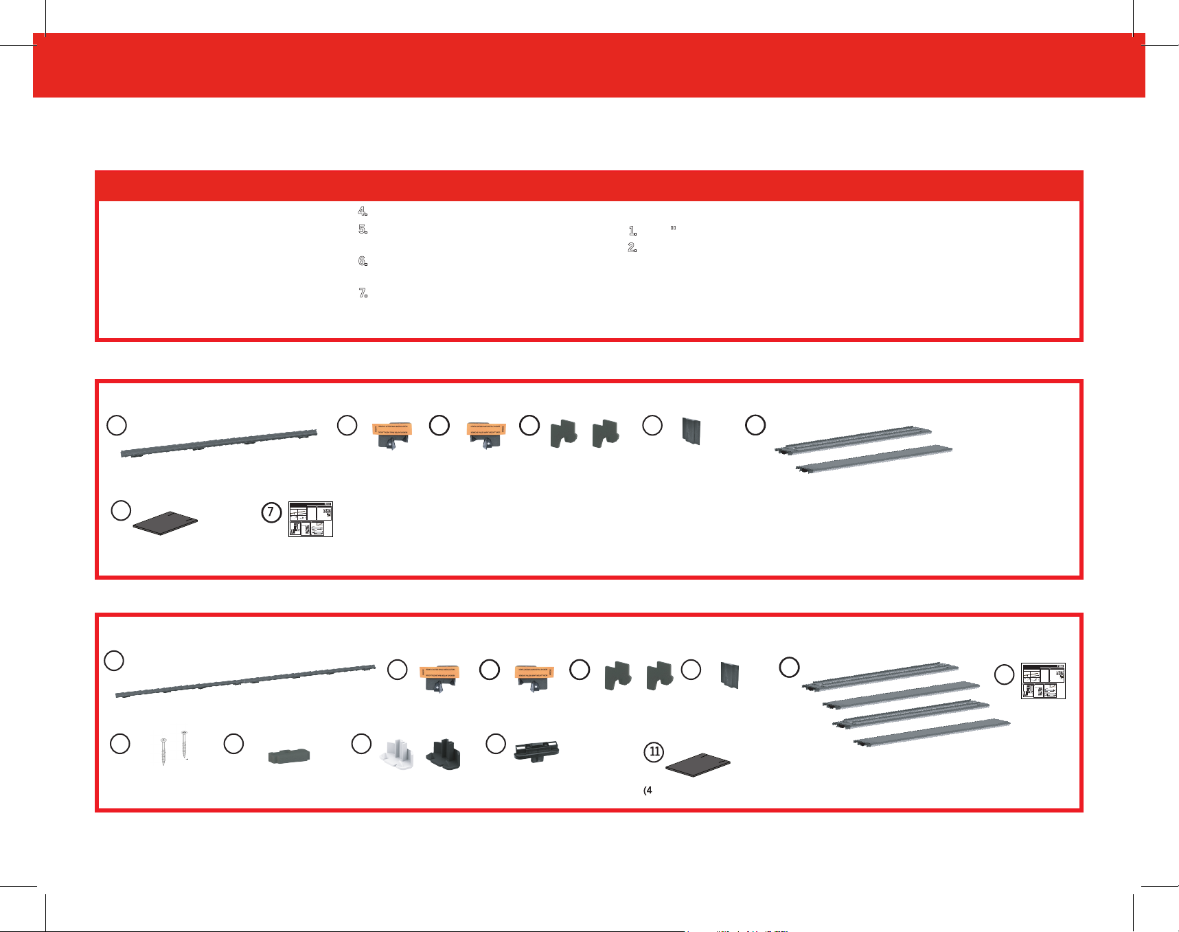
Standard Door (Single) Replacement Kit Contents
1S
1 - 3/0 Z-Articulating Cap
6
(2) Z-AC Door Bottom Gasket
Z-Articulating Cap
Replacement Instructions
THIS INSTRUCTION IS APPLICABLE TO Z-SERIES INSWING SILLS ONLY
Included in replacement kit:
Standard Kit (Single Door)
French Kit (Double Door)
2 Z-Articulating Caps Pre-assembled
1 Z-Articulating Cap Pre-assembled
Left Base
Center
Left Base
Bases
#8 x 1” Screw
1 Pair of Tight Margin Bases
1 Right Base
#8 x 2 1/2”Screw
1 pair of
Corner
Pads
2 Center
1 Kerfed and 1 Staple On Door Bottom
Bases
Remove Corner Pads
2
Remove
TOP DOWN
Simple Solution
VIEW
Corner Pad
of Simple
from each jamb.
Solution
Corner Pad
Weatherstripping
Instructions
2R
Right Z-End Base
Mull Stiffener
8817 West Market Street
Colfax, NC 27235
800.334.2006
www.enduraproducts.com
Measure Spacing Between Door Panel and Cap
Required Tools
1
(This Step applies when replacing Z-Series Adjustable cap only)
1. Flathead Screw Driver:
Ensure cap is adjusted all
to remove Z-Series sill cap.
the way in the down position.
2. Board: to protect aluminum
Remove cap plugs.
a1)
sill deck.
Using a screw driver, turn the
a2)
3. Measuring Tape: for sizing new sill
hardware counter- clockwise
cap before cutting to proper length.
until it stops.
a1) a2) a3)
Center
4. Cutting Tool: Chop saw recommended
Press down on the cap to
a3)
Base
to trim cap to proper length.
ensure it is all the way down.
Right Base
X
Measure distance between the top of the
b)
Center
ADDITIONAL TOOLS FOR FRENCH DOORS
Base
cap and the bottom of the panel at the
1. Pencil: to mark sill cup.
cap end on the latch side. Record this
2. Drill: To drill receiver cap hole.
measurement for step 5.
b)
3. 5/8” Diameter Drill Bit
* For French (double) doors, the measurement should be
2 Kerfed and 2 Staple On Door Bottoms
4. Rubber Mallet: to tap in bolt receiver
taken at the astragal end of each panel
cup.
Make sure to measure to the panel and not to the plastic door
1 Standard or
Structural
2 Center Tight
1 pair of
bottom
5. Power Driver: For anchor screw
Bolt Receiver
Margin Bases
Corner Pads
Remove OLD Sill Cap
Cut NEW Z-Articulating Sill Cap to Length
3
4
Protect aluminum sill deck with a thin
Measure the length
a)
board to prevent damage when prying
of the sill.
off sill cap.
a)
b)
For Single Door applications, measure and cut
Screwdriver
new cap to match length of the sill minus 1/4”
under front leg
Cut cap to
Measure from this end of the cap- do not include pad
of sill cap at one
length at
this end
end. Then pry
a)
sill cap up with
Sill Length minus 1/4”
screwdriver,
working from one
For French (Double) Door applications, cut Both the new
c)
end to the other.
caps to match length of the sill minus 1-1/16” divided by 2.
Measure from this end of the cap- do not include pad
Cut cap to
Pull sill cap out of
b)
length at this
channel.
end
b)
(Sill Length minus 1-1/16”) /2
CAUTION: Measure carefully and cut precisely to ensure proper operation.
to trim cap and door bottom to proper length.
aluminum Deck from Z-AC 1.0/1.1 Pin Capture.
to panel.
2L
Left Z-End Base
Mull Stiffener
3
Left and Right
Active Mull
Stiffener Gaskets
ADDITIONAL TOOLS FOR FRENCH DOORS
1
. 7/8'' Diameter Drill Bit
. Power Driver: For anchor
2
screw
4
1 pair (2) of
Corner Pads
5
1 Kerfed Door Bottom & 1 Staple On Door Bottom
French (Double Door) Replacement Kit Contents
1F
1 - 6/0 Z-Articulating Cap
7 8 9
(2) Pin Capture
Mounting
Screws
(1) Bottom Pad for
Astragal Boot
2R
Right Z-End Base
Mull Stiffeners
Astragal Lower Trim
Cap (White & Bronze)
2L
Left Z-End Base
Mull Stiffeners
10
1 Bolt Receiver Pin Capture
(French Doors Only)
3
Left and Right
Active Mull
Stiffener Gaskets
4
(3) Corner Pads
) Z-AC Door Bottom Gasket
5
(2) Kerfed Door Bottoms & (2) Staple On Door Bottoms
6
8817 West Market Street
Colfax, NC 27235
800.334.2006
Z-Articulating Cap
www.enduraproducts.com
Replacement Instructions
Measure Spacing Between Door Panel and Cap
Required Tools
1
THIS INSTRUCTION IS APPLICABLE TO Z-SERIES INSWING SILLS ONLY
(This Step applies when replacing Z-Series Adjustable cap only)
1. Flathead Screw Driver:
Ensure cap is adjusted all
to remove Z-Series sill cap.
Included in replacement kit:
the way in the down position.
2. Board: to protect aluminum
Standard Kit (Single Door)
French Kit (Double Door)
Remove cap plugs.
a1)
sill deck.
2 Z-Articulating Caps Pre-assembled
Using a screw driver, turn the
a2)
1 Z-Articulating Cap Pre-assembled
3. Measuring Tape: for sizing new sill
hardware counter- clockwise
cap before cutting to proper length.
until it stops.
a1) a2)
Center
4. Cutting Tool: Chop saw recommended
Press down on the cap to
a3)
Base
Left Base
to trim cap to proper length.
ensure it is all the way down.
Right Base
Measure distance between the top of the
b)
Center
Left Base
Center
ADDITIONAL TOOLS FOR FRENCH DOORS
Bases
Base
cap and the bottom of the panel at the
1. Pencil: to mark sill cup.
cap end on the latch side. Record this
2. Drill: To drill receiver cap hole.
#8 x 1” Screw
measurement for step 5.
3. 5/8” Diameter Drill Bit
* For French (double) doors, the measurement should be
1 Pair of Tight Margin Bases
1 Right Base
2 Kerfed and 2 Staple On Door Bottoms
#8 x 2 1/2”Screw
4. Rubber Mallet: to tap in bolt receiver
taken at the astragal end of each panel
1 pair of
Corner
cup.
Make sure to measure to the panel and not to the plastic door
1 Standard or
Pads
Structural
2 Center Tight
2 Center
1 pair of
bottom
1 Kerfed and 1 Staple On Door Bottom
5. Power Driver: For anchor screw
Bolt Receiver
Margin Bases
Bases
Corner Pads
Remove Corner Pads
Remove OLD Sill Cap
Cut NEW Z-Articulating Sill Cap to Length
3
2
4
Protect aluminum sill deck with a thin
Measure the length
Remove
a)
board to prevent damage when prying
of the sill.
TOP DOWN
Simple Solution
off sill cap.
VIEW
Corner Pad
of Simple
from each jamb.
Solution
a)
b)
For Single Door applications, measure and cut
Corner Pad
Screwdriver
new cap to match length of the sill minus 1/4”
under front leg
Cut cap to
Measure from this end of the cap- do not include pad
of sill cap at one
Weather-
length at
this end
stripping
end. Then pry
a)
sill cap up with
Sill Length minus 1/4”
screwdriver,
working from one
For French (Double) Door applications, cut Both the new
c)
end to the other.
caps to match length of the sill minus 1-1/16” divided by 2.
Measure from this end of the cap- do not include pad
Cut cap to
b)
Pull sill cap out of
length at this
channel.
end
b)
(Sill Length minus 1-1/16”) /2
CAUTION: Measure carefully and cut precisely to ensure proper operation.
Instructions
X
1
ENDURA P R ODU C T S >INS T R U C TIONS> Z - A C™ F IELD R E PLA CEME N T INS T R U C TIONS
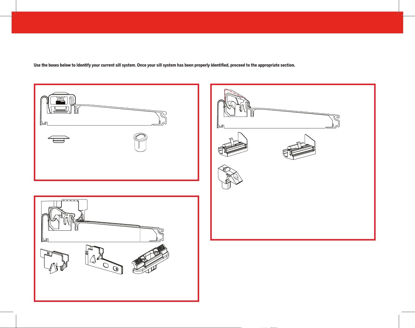
Identifying Your Sill System
Z-Series Adjustable Sill (ZAI )
ZAI to Z-AC 2.0
ZAI Sill
Screw Hole
Cover
ZAI Features
• Flat Cap
• Screw Hole Covers
• Receiver Cup Under Cap
Z-Series Articulating Sill 2.0 (Z-AC 2.0 )
Z-AC 2.0 to Z-AC 2.0 SEE PAGE 28
Z-Series Articulating Sill 1.0/1.1 (Z-AC 1.0/1.1 )
SEE PAGE 4 Z-AC 1.0/1.1 Z-AC 2.0 SEE PAGE 16
Z-AC Sill 1.0/1.1 Sill
Bolt Receiver Cup
(French Doors Only)
Z-AC 1.0/1.1 Features
• Slanted Cap
• End Bases with Angular/Slanted Rigid
Wall
• Exposed Pin Capture
1.0 Angular
End Base
1.0/1.1 Pin Capture
(French Doors Only)
1.1 Slanted
End Base
Z-AC Sill 2.0 Sill
Z-End Base
Z-AC 2.0 Features
• Slanted Cap
• Z-End Bases with Weatherstrip Locator
2.0 Pin Capture
(French Doors Only)
• Pin Capture Under Cap
2

E NDU R A P R ODU C T S >INS T R U C TIONS> Z - A C™ F IELD R E PLA CEME N T INS T R U C TIONS
Z-Articulating Cap Sill Field Replacement Instructions
Table of Contents
ZAI to Z-AC 2.0 PAGE 4
1. Remove Corner Pads Page 5
2. Remove OLD Adjustable Cap Page 6
3. Install Z-End Base Mull Stiffeners Page 7
4. Cut NEW Z-Articulating Sill Cap to Length Page 8
5. Check Cap Assembly Page 10
6. Install Z-AC 2.0 Pin Capture From An Adjustable Sill
Page 11
7. Insert NEW Sill Cap Page 13
8. Drill Cap For Astragal Bolt Page 14
9. Replace Astragal Bottom Sealing Pad and Corner Pad
Page 15
10. Replace Door Bottom Sweep Page 16
11. Stapling Door Bottom to Panel Page 17
12. Replace Corner Pads Page 18
13. Check the Operation of the Door Page 18
Z-AC 1.0 & 1.1 to Z-AC 2.0 PAGE 16
1. Remove Corner Pads Page 17
2. Remove OLD Z-AC 1.0/1.1 Page 18
3. Install Z-End Base Mull Stiffeners Page 18
4. Cut NEW Z-Articulating Sill Cap to Length Page 19
5. Check Cap Assembly Page 20
6. Install Z-AC 2.0 Pin Capture When Converting From
ZAC 1.0/1.1 Page 21
7. Insert NEW Sill Cap Page 22
8. Drill Cap For Astragal Bolt Page 23
9. Replace Astragal Bottom Sealing Pad and Corner
Pad Page 24
10. Replace Door Bottom Sweep Page 25
11. Stapling Door Bottom to Panel Page 26
12. Replace Corner Pads Page 27
13. Check the Operation of the Door Page 27
Z-AC 2.0 to Z-AC 2.0 PAGE 28
1. Remove Corner Pads Page 29
2. Remove Z-AC 2.0 (Single and French) Page 30
3. Remove Z-AC 2.0 (Sidelite, Hinged Patio and
Page 31
4. Cut NEW Z-Articulating Sill Cap to Length Page 32
5. Check Cap Assembly Page 33
6. Install New Z-AC Pin Capture Page 34
7. Insert NEW Sill Cap Page 35
8. Drill Cap For Astragal Bolt Page 36
9. Replace Astragal Bottom Sealing Pad and Corner Pad
Page 37
10. Replace Door Bottom Sweep Page 38
11. Stapling Door Bottom to Panel Page 39
12. Replace Corner Pads Page 40
13. Check the Operation of the Door Page 40
3

ENDURA P R ODU C T S >INS T R U C TIONS> Z - A C™ F IELD R E PLA CEME N T INS T R U C TIONS
Z-Series Adjustable Sill (ZAI )
ZAI Sill
Screw Hole Cover
ZAI Features
• Flat Cap
• Screw Hole Covers
ZAI Receiver Cup
(French Doors Only)
• Receiver Cup Under Cap
4

E NDU R A P R ODU C T S >INS T R U C TIONS> Z - A C™ F IELD R E PLA CEME N T INS T R U C TIONS
1. Remove Corner Pads (ZAI to Z-AC 2.0)
a)
Remove the weatherstrip by pulling it
out of the kerf slot.
b)
(If Present) Remove Simple Solution
Corner Pad from each jamb by peeling
it off.
c)
Clean any residual debris and dirt from
the jamb.
d)
Proceed to Step 2.
a)
b)
TOP DOWN
VIEW
of Simple
Solution
Corner Pad
Weatherstripping
*
*Corner Pad may be look different.
Removal process will not change.
5

ENDURA P R ODU C T S >INS T R U C TIONS> Z - A C™ F IELD R E PLA CEME N T INS T R U C TIONS
2. Remove OLD Adjustable Cap (ZAI to Z-AC 2.0)
Protect aluminum sill deck with a
small wood block to prevent damage
a)
when prying off sill cap.
a)
Place a
front leg of sill cap at one end. Then pry
sill cap up with screwdriver, working
from one end to the other.
b)
Pull sill cap out of channel.
c)
Clean any debris out of sill channel and
b)
on the jambs.
d)
Proceed to Step 3.
3. Install Z-End Base Mull Stiffeners (ZAI to Z-AC 2.0)
Insert Z-End Base Mull Stiffeners 2L & 2R into each side of the
a)
channel against the jambs
a)
2
2
NOTE: The Z-End Base Mull Stiffeners are handed and can only
be inserted one way. The back of the Z-End Base Mull Stiffener
NOTE: Do not caulk or staple the Z-End Base Mull Stiffeners in
place.
NOTE: Do not remove the orange protective gasket label until
cap is fully installed into the door unit.
Proceed to Step 4.
b)
Jamb
Z-End Base Mull Stiffeners
2L
2R
6
E NDU R A P R ODU C T S >INS T R U C TIONS> Z - A C™ F IELD R E PLA CEME N T INS T R U C TIONS
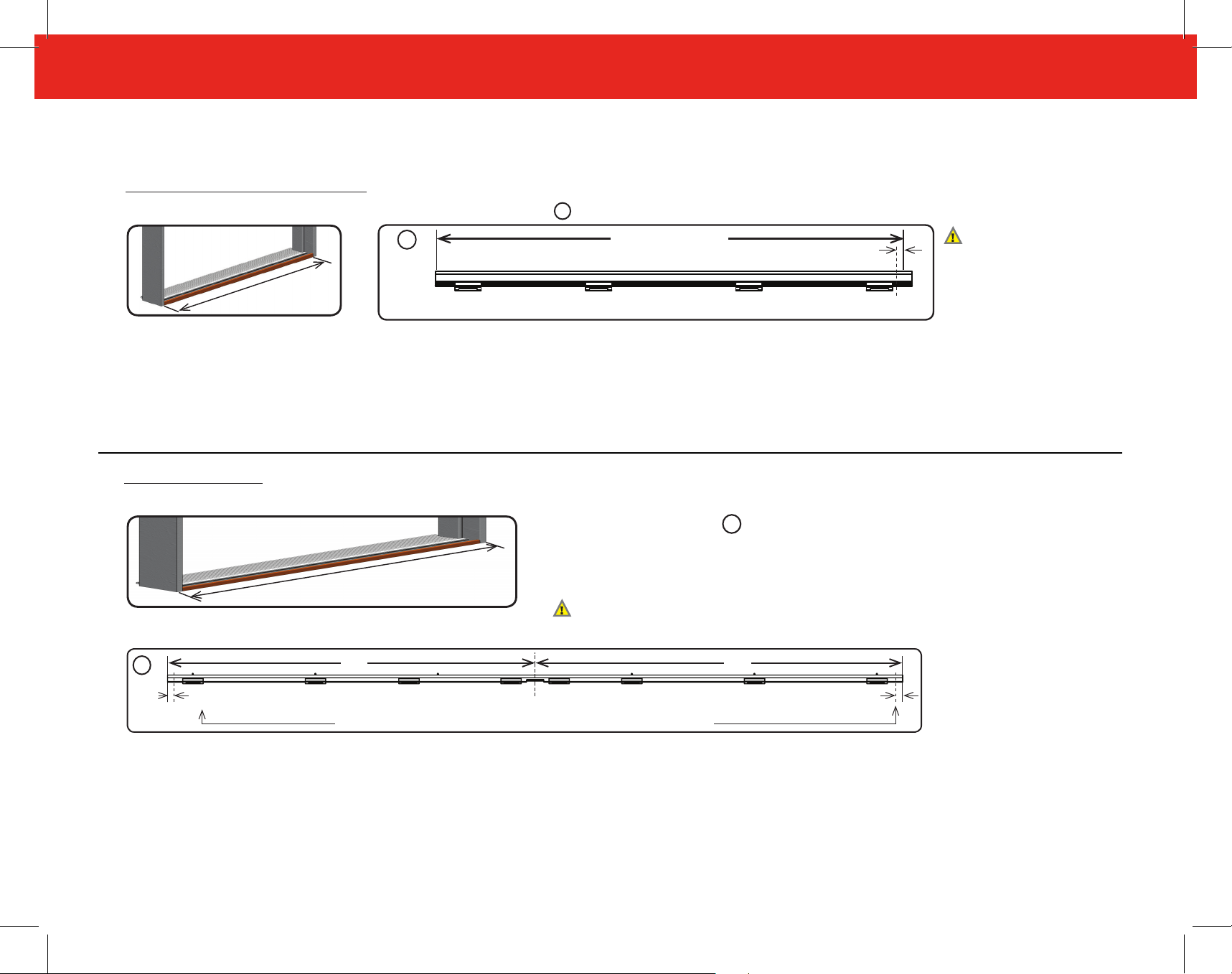
4. Cut NEW Z-Articulating Cap to Length (ZAI to Z-AC 2.0)
FOR SINGLE, SIDELITE AND HINGED PATIO DOOR APPLICATIONS
Measure the length of the sill (X).
a)
b)
Measure and cut new cap 1s to match length of the sill minus 1/4".
1S
Sill Length (X)
x
c)
Proceed to step 5.
FOR FRENCH (DOUBLE) DOOR APPLICATIONS
1/4"
Cut Here
CAUTION: Measure
carefully and cut
precisely within 1/32'' to
ensure proper operation.
A cap cut too short will
not seal correctly.
Measure the length of the sill (X).
a)
1F
Cut 1/8" from each end
c)
Proceed to step 5.
b)
Measure and cut new cap 1F to match length of the sill (x) minus 1/8" on each side.
• Cut on both ends to ensure notch remains in center cap.
• Cap should be the same length on each side of the center of notch -
x
Approximately 1/2 of sill length (X/2) minus 1/8".
CAUTION: Measure carefully and cut precisely within 1/32” to ensure
proper operation. A cap cut too short will not seal correctly.
X/2 X/2
Pin Capture Notch
If needed, move the bases at the end of the caps to the inside (1/2” from the end)
Cut 1/8" from each end
7
ENDURA P R ODU C T S >INS T R U C TIONS> Z - A C™ F IELD R E PLA CEME N T INS T R U C TIONS
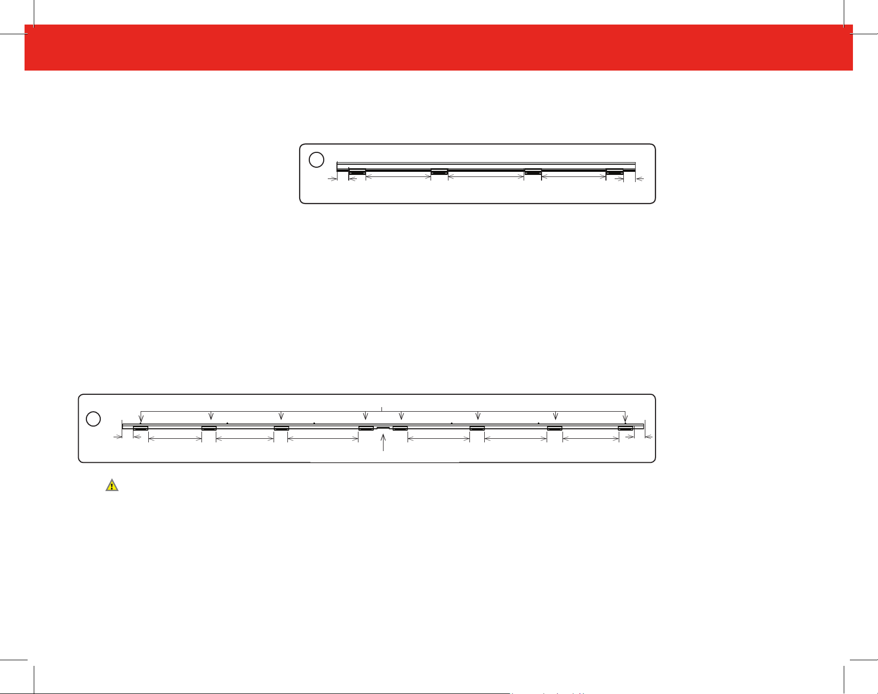
5. Apply Spring-Loaded Cap Bases (ZAI to Z-AC 2.0)
SINGLE, SIDELITE AND HINGED PATIO DOORS ONLY
a)
Ensure that all 4 spring-loaded bases are used
and properly positioned.
• The spring-loaded bases at the ends of the
cap should be 1" to 1-1/2" from the cap’s
edge.
• The two spring-loaded center bases
should be evenly spaced between the 2
spring-loaded bases at the ends of the cap,
approximately 9"-10" inches apart (y).
b)
Proceed to step 6.
FRENCH (DOUBLE) OPENING DOORS ONLY
a)
Ensure that all 8 spring-loaded bases are used and properly positioned.
• The spring-loaded bases at the ends of the cap should be 1" to 1-1/2" from the cap’s
edge.
• The 4 center spring-loaded bases should be evenly spaced between the 2 spring-loaded
bases at the ends of the cap, approximately 10"- 11" inches apart (Y).
1F
1S
1” to 1-1/2”
Y Y Y
Bases
1” to 1-1/2”
1" to 1-1/2"
Note: Bases in the center of the cap should be installed on either side of Pin Capture Notch leaving room for pin capture, which
will be installed in the next step
b)
Proceed to step 6.
Pin Capture Notch
YYY Y YY
1" to 1-1/2"
8

E NDU R A P R ODU C T S >INS T R U C TIONS> Z - A C™ F IELD R E PLA CEME N T INS T R U C TIONS
French Doors Only
1/2X
X
6. Install New Z-AC Pin Capture When Converting From An Adjustable Sill
LOCATE AND DRILL PIN CAPTURE HOLE
NOTE: If hole already exists from previous bolt receiver cup, the
old hole can be used, provided it is centered exactly in the sill
from end to end. Simply drill a 7/8" diameter hole deep through
the sill substrate in its place .
If the hole is not completely centered, Follow the below steps.
a)
Measure sill length from jamb to jamb (X).
Mark the cap channel at exactly 1/2 the sill length and 7/16" from
b)
the interior of the sill dam.
Drill 7/8" diameter hole deep through the sill substrate (17/32"
c)
deep). This is where the pin capture 10 will be inserted.
INSTALL PIN CAPTURE
Fill bottom of pin capture hole with exterior grade caulking.
a)
Insert pin capture 10 into hole and tap into place with a rubber
b)
mallet, if necessary.
Insert two provided screws 7 into mounting holes on pin
c)
capture.
d)
Proceed to step 7.
(ZAI to Z-AC 2.0)
a)
X/2
c)
Drill
7/8" x 17/32" Deep
a)
Orientation of Z-AC 2.0 Pin Capture
10
Z-AC 2.0 Pin Capture
b)
b)
7/16"
7/8"
10
c)
7
Exterior
9

ENDURA P R ODU C T S >INS T R U C TIONS> Z - A C™ F IELD R E PLA CEME N T INS T R U C TIONS
7. Insert NEW Sill Cap (ZAI to Z-AC 2.0)
FOR SINGLE, SIDELITE, HINGED PATIO AND FRENCH DOOR UNITS
a)
Press one end of cap 1 into channel and
against Z-End Base/ Mull Stiffener 2 .
b)
Bend cap 1 slightly upward in center then and
press opposite end into channel and against
Z-End Base/ Z-End Base Mull Stiffener 2 .
c)
Apply Pressure to the cap 1 to fully seat cap into
place along entire length of sill.
a)
b)
Front leg of the cap should touch the deck
when seated.
d)
Depress the cap 1 , to gain access to the orange
protective labels on each Z-End base/ Mull Stiffener
(If Present).
e)
Grasp the inside tab of the orange protective label
on the Z-End base/ Mull Stiffener, shown here (If
Present), and lift up and away from the Z-End Base.
A small portion of the active stiffener will be
removed with the label. This is normal.
f)
Insert weatherstrip by fully installing/placing leg fully
into frame kerf slot. Be sure that the Weatherstrip
contacts the Weatherstrip Locator on the Z-End
Base/ Mull Stiffener.
g)
Proceed to step 8.
c)
e)
Grasp Tab Here
f)
Should
contact sill
deck
d)
Weatherstrip
Leg
Kerf Slot
10
E NDU R A P R ODU C T S >INS T R U C TIONS> Z - A C™ F IELD R E PLA CEME N T INS T R U C TIONS
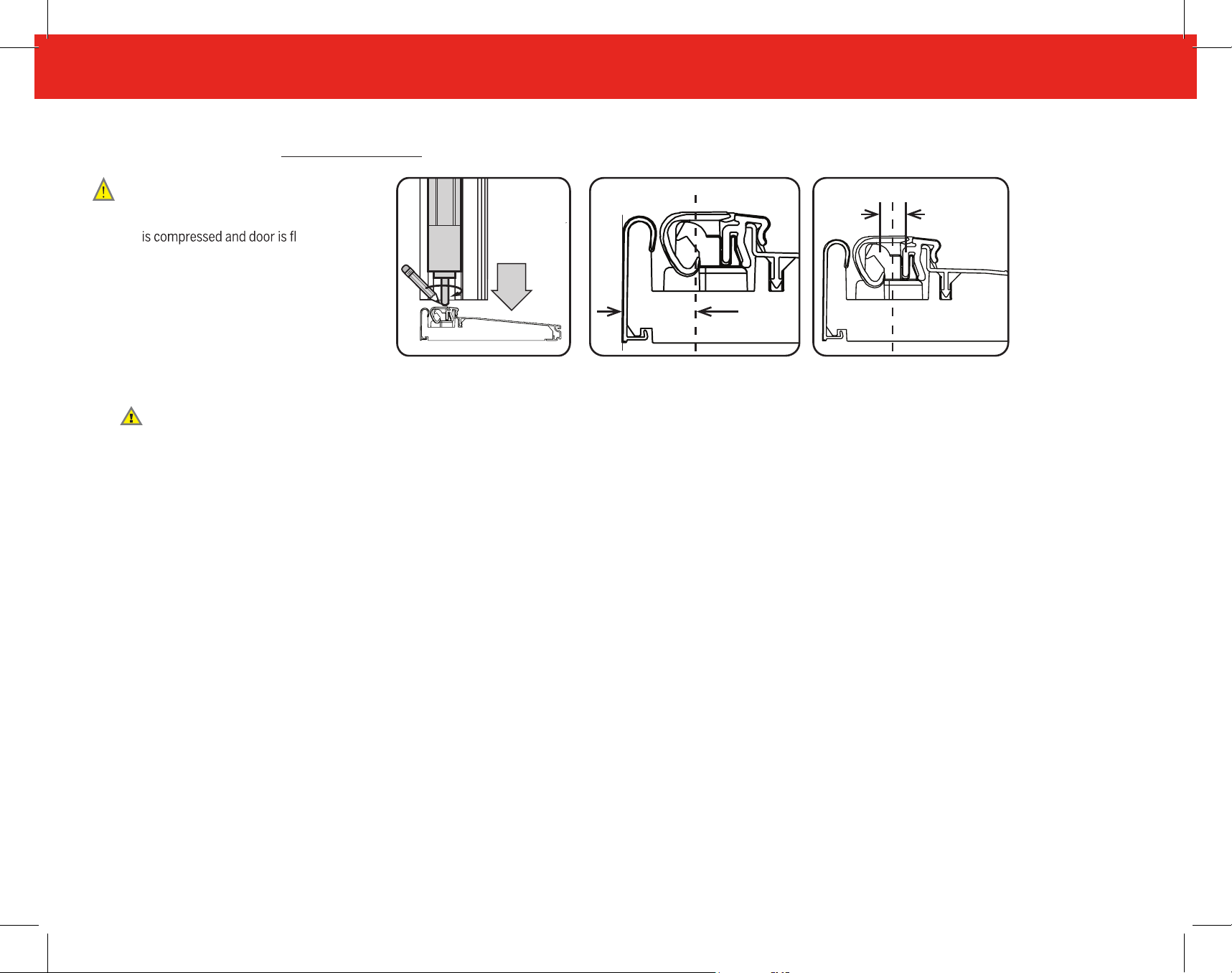
French Door Units Only
8. Drill Cap For Astragal Bolt
FOR FRENCH DOOR UNITS
a)
Close passive door until header weatherstrip
opening. Engage astragal bolt to contact and
compress Z-AC to mark for drilling.
b)
The center of the mark made should be
7/8" from the interior edge of the sill.
c)
Depress the cap, and using a 5/16" drill bit,
drill a hole in the cap.
Stop drilling once you drill through the cap!
d)
Proceed to step 9.
ush with the
(ZAI to Z-AC 2.0)
a)
7/8"
c)b)
5/16"
11
ENDURA P R ODU C T S >INS T R U C TIONS> Z - A C™ F IELD R E PLA CEME N T INS T R U C TIONS
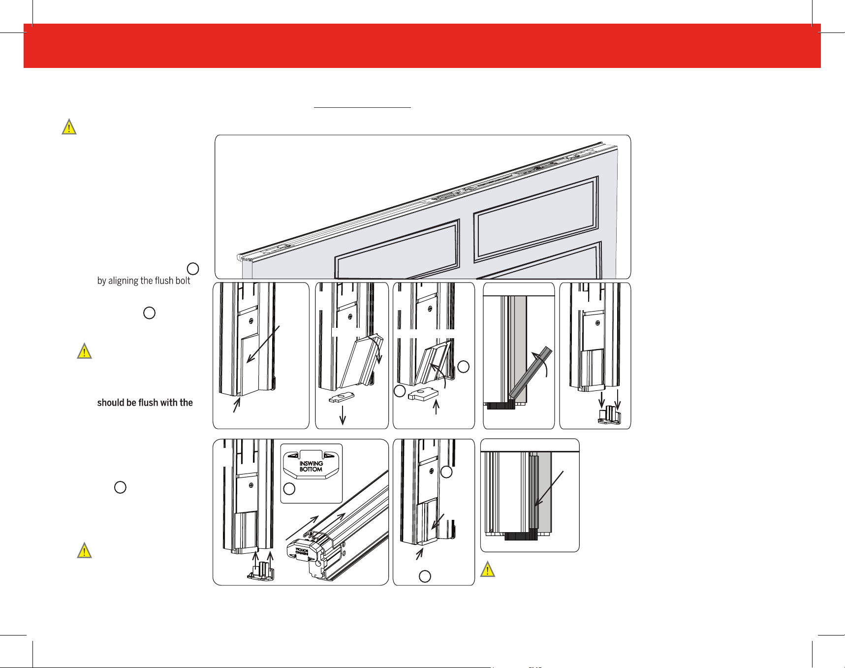
French Door Units Only
9. Replace Astragal Bottom Sealing Pad and Corner Pad
FOR FRENCH DOOR UNITS
Remove inactive door panel
a)
off its hinges to gain access
to the bolt sleeve with
corner pad and bottom
sealing gasket.
Remove corner pad and
b)
bottom sealing gasket by
peeling down and away
from the astragal.
Install new Z-AC Astragal
c)
Bottom Sealing Gasket 8
with the hole in the pad c1
then install Simple Solution
Corner Pad 4 by tipping
into place c2.
The lip of the Bottom
Sealing Gasket should
extend out in front of the
astragal, and the Simple
Solution Corner Pad
a)
Corner
Pad
b)
Peel Off
(ZAI to Z-AC 2.0)
Side View
c) d)
c2. Tip into place
4
8
top of the gasket.
Remove original Lower Trim
d)
Cap by prying it off of the
bottom of the astragal.
e)
Align the new Lower Trim
Cap 9 with the astragal
body, and Insert the Trim
cap into the bottom of the
astragal.
Use the trim cap that
matches astragals body
color. Discard the other.
Proceed to step 10.
f)
Bottom Sealing Gasket
e)
9
New Lower
Trim Cap
c1. Install Pad
4
New
Corner
Pad
Bottom Sealing
Pad 8
Bottom Sealing Gasket
extends past bolt Sleeve
Side View
New Corner Pad
Corner Pad should
contact the top of the
Bottom Sealing Pad
12
 Loading...