

Endura XL100, XL75, 4075A04, 40100A04M, 4075A04M Installation Operation & Maintenance
...
GREA
SE INT ERC EPT OR
G
R
EASE I NTE RCE PTO R
GREA
SE INT ERC EPT OR
G
R
EASE I NTE RCE PTO R
GREASE IN TER CEP TOR
G
R
EASE I
N
TERCEP TOR
GREASE IN TER CEP TOR
G
R
EA
SE I
NTERCE PTOR
X
*
Manual 40100-32
05/17
INSTALLATION, OPERATION & MAINTENANCE
As a plumbing appurtenance your Endura® grease interceptor MUST
WARNING!
be isolated from the drainage system in the event that nal drain
testing or other system pressure testing is required. DO NOT under
any circumstances subject your interceptor to pressure test (Air,
Water or Otherwise). This action will result in damage to the unit,
DO NOT PRESSURE TEST
invalidate your warranty and could cause serious bodily injury.
RISK OF SERIOUS INJURY
Technical Support
tech-support@endurainterceptor.com
Canada
Tel: (705) 726-3361
1-800-461-1771
Fax: (705) 726-2186
U.S.A
Tel: (303) 373-1918
1-888-461-5307
Fax: (303) 373-1923
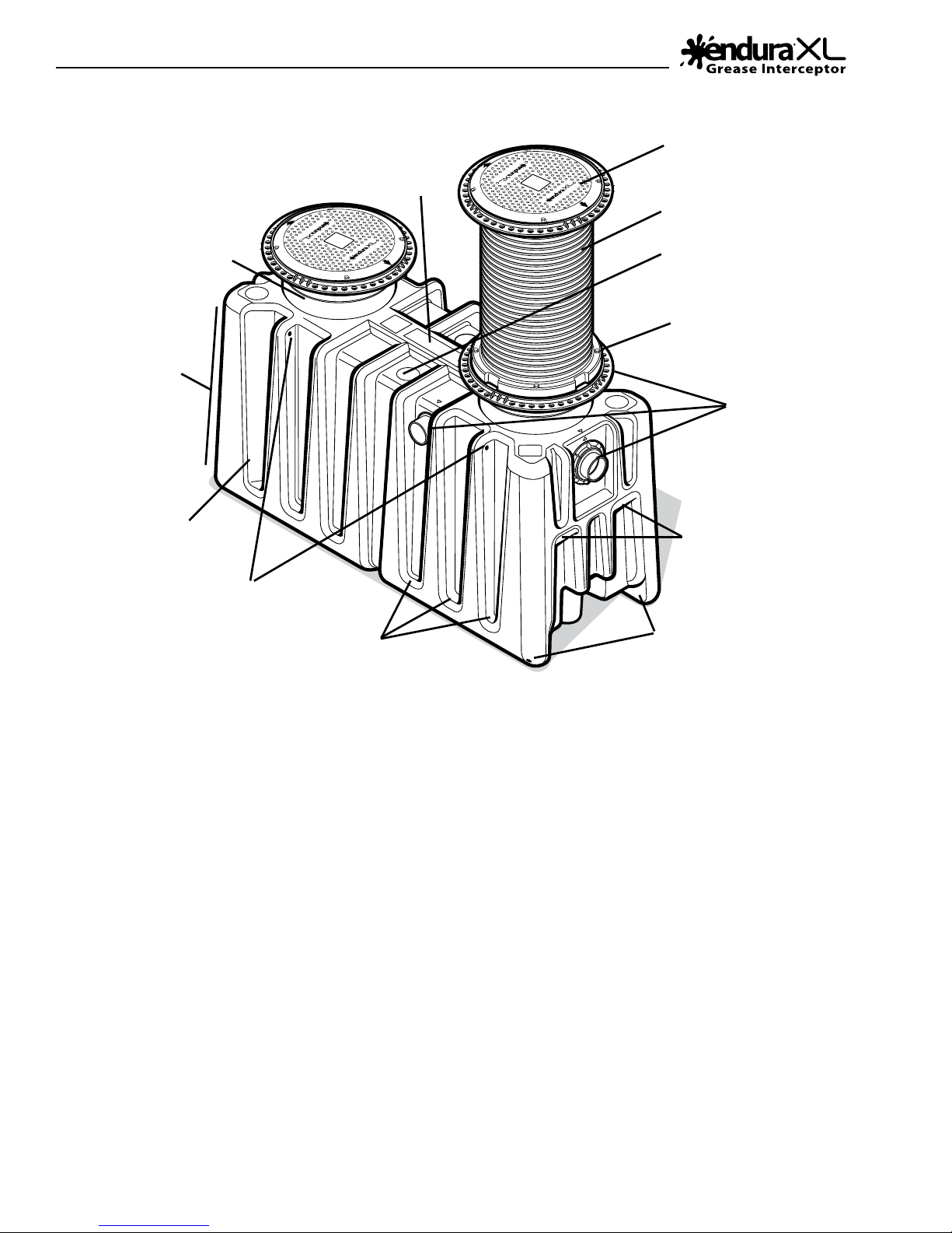
Features Overview
AIR BALANCED
ENVIRONMENT
GREASE IN TER CEP TOR
BUILT-IN HEIGHT
ADJUSTMENT
TANK PROFILE
RESISTS
FLOTATION
CORRUGATED WALLS
FOR STRENGTH
GREASE IN TER CEP TOR
LOAD RATED
GREASE IN TER CEP TOR
GREASE IN TER CEP TOR
COVER & FRAME
CUT TO SUIT RISER
EXTENSION
REMOTE PUMP READY
AIR & WATER TIGHT
EXTENSION SYSTEM
FACTORY PLUMBED
3-WAY OUTLET
SYSTEM
MANUAL
LIFTING
POINTS
INTEGRATED LIFTING
LOCATIONS
INTEGRATED TIE DOWN
CLOSED RIBS FOR
FLOTATION RESISTANCE
LOCATIONS
About Your Purchase:
The Endura® XL grease interceptor and it associated products are the latest addition to the proven line of Endura®
Grease Management products.
We have spent many thousands of hours in the development of Endura® XL, our aim being simple – to produce
the industry’s best Hydromechanical Grease Interceptor.
From the ground up, Endura® XL has been ‘Engineered for Easy’. Working with distributors, installers, engineers,
jurisdictional ocials, pumpers and of course restaurant operators across North America, we have taken all of
the feedback gained and rolled it into one comprehensively designed solution to meet as broad a range of these
requirements as possible.
Endura® XL is the most widely evaluated and approved hydromechanical interceptor in the current marketplace,
being successfully tested by independent third parties to meet all requirements of PDI G-101, ASME A112.14.3
(Type A & C) / NSF ES15741 and CSA B481.1.
*Endura brand products manufactured by Canplas Industries.
- 2 -

Table of Contents
Page
Features Overview 2
Glossary 3
Quick Start Installation Guide 4
Technical Information 6
Installation Specifications 8
Installation 11
Installation - Flow Controls 12
Remote Pump (optional) 13
Glossary of Terms
HGI: Industry abbreviation for Hydromechanical
Grease Interceptor. By denition an HGI is designed to use
managed ow, air entrainment and specically designed
features to provide an enhanced level of separation
eciency, removing non petroleum FOG (Fats, Oil and
Grease) from a transition ow of waste water, generated by
commercial foodservice activities (Restaurants, Cafeterias,
Institutional Kitchens , Sandwich Shops and Coee houses
for example). HGI’s are performance tested for eciency of
grease separation based on National Standards.
Operational Cost Index =1
GGI: Industry abbreviation for Gravity Grease
Interceptor. By denition a GGI has a minimum of 350USG
capacity and in operation 500USG to 1500USG of capacity
are most common. No ow control device. Separation
of FOG based on capacity and retention time of water
(minimum 30 min. to exchange volume). At this time no
performance Standards are published for GGI’s.
Operational Cost Index HGI = 5 GGI = 10+
Page
Installer Checklist 14
Operation 15
Maintenance 16
Pumper Checklist 18
Trouble Shooting 19
Frequently Asked Questions 20
Warranty 23
Registration Card 24
25% Rule: The rule of thumb, sometimes mandated
by jurisdiction, used to determine frequency of pump
out for GRAVITY GREASE INTERCEPTORS. The 25% refers
to the combined volume or retained FOG and food solids
which shall not exceed 25% of the working volume of the
interceptor. This rule should not typically be applied to HGI’s
particularly those with extended capacity.
Cost Index: A way of indicating the relative cost
of dierent types of interceptor to each other for broad
comparison purposes. This includes product purchase,
installation cost and typical maintenance.
Air Entrainment: Mixing of air with Inuent using
a ow control device. Air and grease are attracted to each
other, the air wanting to separate more easily than grease.
Because they become mixed together the air increases the
eciency of separation.
Euent: Waste water containing little to no FOG,
being discharged out of the interceptor.
GRD: Industry abbreviation for Grease Removal
Device. Designed rstly as an HGI, a GRD uses a heat source
and a timed or sensor based skimming (or draw-o ) device
to remove accumulated FOG from the separation chamber
into an external container for collection and disposal. These
units require daily maintenance for management of food
solids. Operational Cost Index HGI = 2.5 GGI = 5
– Available online – Mobile Friendly
BMP
– Best Management Practices
Inuent: Waste water containing uncontrolled
and variable levels of FOG based on the nature and
practices of the foodservice operation.
Separation Chamber: Zone inside the
interceptor where grease separates from water and is
retained.
AHJ: Authority Having Jurisdiction. This can be
one or more government departments - for example plan
check/review, building, plumbing, pretreatment, sewer and
waste water. Bottom line...those who enforce the rules and
regulations.
- 3 -
Quick Start Guide
tO
Ensure adequate room for
piping connections
and inspections
G
REASE INTE
RCEP
T
OR
GREASE INT
ERC
EPTOR
G
REASE INTE
RCEP
T
OR
GREASE INTERC
EPTOR
Cleanout
OUTSIDE -
OUT
IN
Cleanout
Cleanout
Max. 25ft
FCD Air Intake
PDI
External Flow
Control. Located
as close as possible to
the last fixture
Cleanout Cleanout
Sink
Flow
Quick Start Guide
Before you begin, be sure to review this document in full for important information regarding
the installation process. Also, ensure that the interceptor purchased is correctly specied and
sized for the intended installation. Be sure to reference and be familiar with local code and
municipal FOG Program requirements. The Authority Having Jurisdiction (AHJ) can be your
best friend and your worst enemy.
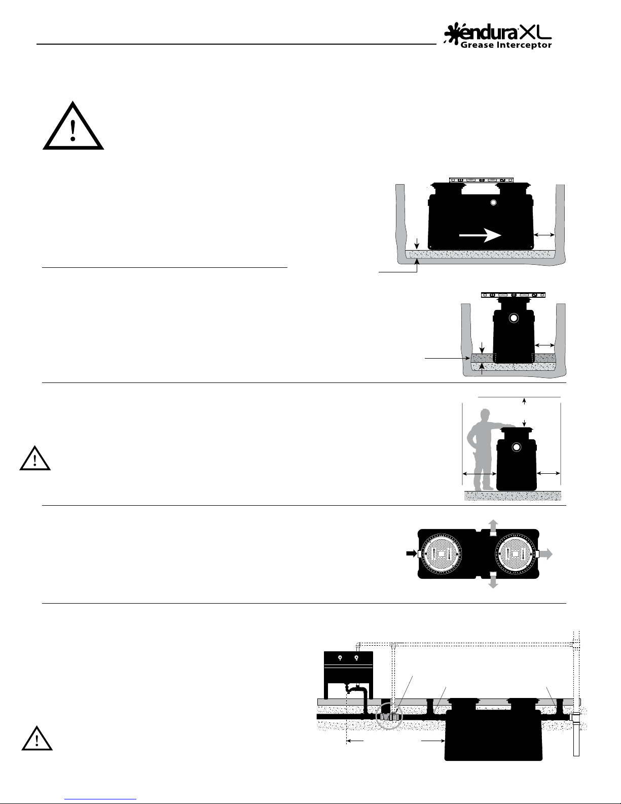
1. Prepare your
installation area
If installing in-oor or below grade excavate as required
to accommodate the interceptor and ensure safe
working practices. Refer to Installation Specication
section of this document (See Page 8-10).
2a. In ground/oor
Remove all packaging, including the skid. Conrm ow direction,
lower in and level interceptor accounting for anticipated surface
nish requirements.
Note: For installations where high ground water is anticipated,
once located pour at least 8” of concrete on top of your prepared
base, to ll an area around the perimeter of the tank. This will prevent
otation. For alternative methods of anchoring (See Page 8-10).
Min. Base
6" Minimum Base
of Crushed aggregate
material approximately
3/4" size rock, pea
gravel or sand
Anchoring
(if required)
Concrete Anchor
Base (if anchoring
Inle
Min.
is required)
Level end to end
Flow Direction
6"
Level side to side
Min.
8"
utlet
Min.
12"
Min.
12"
2b. On oor/oor below
Remove all packaging including the skid. Locate the interceptor so as to allow for accessibility
when conducting maintenance and regular cleaning. Set the interceptor on a rm, level
surface ensuring tank is equally supported.
When full the weight of the tank is signicant (XL75 Approx. 1300lbs [590kg]),
XL100 Approx. 2150lbs [975kg])
For suspended application engineering service by a qualied engineer will be necessary.
A minimum safety factor of 2 shall be applied in calculation/design.
Sink
IN
PDI
External Flow
Control installation
FCD Air Intake
Max. 25ft
(for PDI)
3. Select preferred outlet connection
Connect your inuent drain to the tank inlet (“IN”). Select the preferred outlet
connection from the pre-plumbed connection ports oered – marked “OUT”.
Side connection is accessed by removal of the caps supplied, that cap then being
used to seal the end outlet.
4. Installations with External Flow Control
(PDI G-101/ASME A112.14.3 - Type A)
For PDI G-101/ASME A112.14.3 (External Flow Control)–
Install the ow control device (purchased separately)
upstream, after the last branch connection discharging to the
interceptor. A maximum of 25ft from last branch discharge
to the entry of the interceptor is required to meet published
recommendations. See Page 12 for connection formats.
Plumbing code typically requires provision of a cleanout
to grade immediately before and after the inlet and outlet
connections.
GREASE INTERC
OR
T
RCEP
EPTOR
REASE INTE
G
SIDE -
See page 6 for
cleanout part numbers
Cleanout
Inlet
Ensure adequate room for
piping connections
and inspections
GREASE INT
OR
T
RCEP
ERC
EPTOR
REASE INTE
G
OUT
Outlet
END - OUT
Cleanout
- 4 -
Quick Start Guide
Native
soil
Min.
6"
Fill with water to static level
Fill with water to static level
Native soil
Concrete slab
Continue fill of
Crushed aggregate
material approximately
3/4" size rock,
pea gravel or sand
72”
Maximum
height
Vehicular traffic reinforced concrete
8"
X
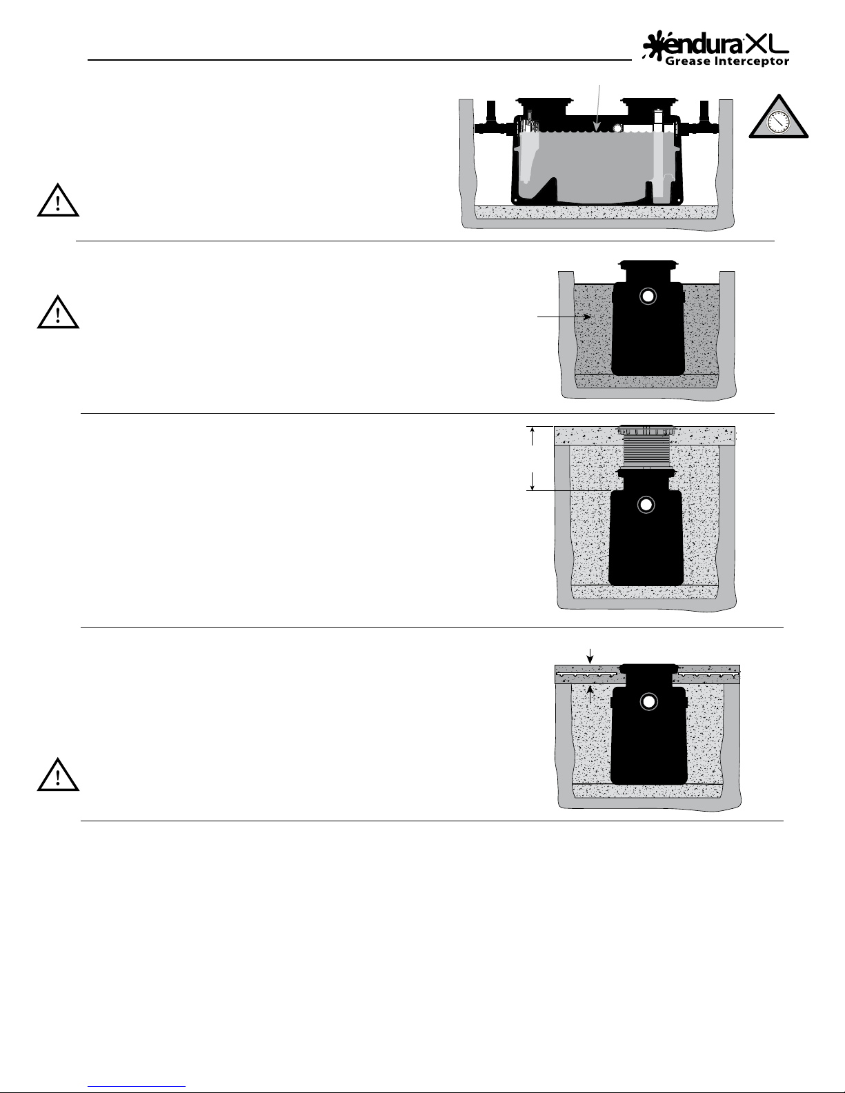
5. Fill tank
Fill tank with water to static water level. This provides stability
and crush resistance during backlling. Check connections made
for any leaks.
For inspection testing DO NOT PRESSURE the tank. Plug
lines inside interceptor to test upstream and downstream
integrity.
6. Replace cover(s) and backll
Replace cover(s) and protect with cardboard or similar
during back lling. Backll per specication (See Page 8).
If installing Remote Pump option do so now (See Page 13)
material approximately
For Spec See Page 8-9
Continue fill of
Crushed aggregate
3/4" size rock,
pea gravel or sand
WARNING!
DO NOT
PRESSURE TEST.
RISK OF SERIOUS
INJURY.
7. Riser Extensions (optional)
Depending on your application, extend the tank risers
(using 40100AX35) to grade/oor level. Be sure to account
for nishing. (Refer to Manual 40100X35-8 – Riser Extension
Installation Guide)
8. Finish to grade / oor
For in ground applications with vehicular trac, the upper 8” requires a
reinforced concrete slab. Refer to the Installation Specication section of
this document (See Page 8-9). This details backll materials and concrete
reinforcement requirements.
If installing in internal application with tiled oor, ensure adequate
protection to prevent mortar from covering bolts, and/or entering
around cover perimeter.
9. Completion documentation
Having completed installation and successful inspection, hand-over to the client all installation documentation, with page 14
completed. Fill out your sections of the Limited Lifetime warranty registration (See Page 24).
72”
Maximum
height
Reinforced concrete pad for traffic rated installations
8"
If submitting on behalf of your client you can do so at www.EnduraWarranty.com or by sending to the locations shown on
the back cover of this document.
- 5 -
Technical Information
Grade
.625" Raised Cover
10,000 lb
4536 kg
20
21
14
15
16 17
22
Air Balance/
Sampling Cap
13
is ESSENTIAL to
the operation of
the interceptor.
- 6 -
18
19
All images are for illustrative
purposes only. Actual parts
my dier.
Access Covers
Trac Rated CSA B481.0 Type ‘S’
10,000 lb
4536 kg
S
Grade
.625" Raised Cover
Pedestrian/Light Trac Rated
CSA B481.0 Type ‘M’
2000 lb
907 kg
M
Cover Flush to Grade
10
11
12
9
Mechanical
Joint couplings
(by others)
1 52 63 74 8
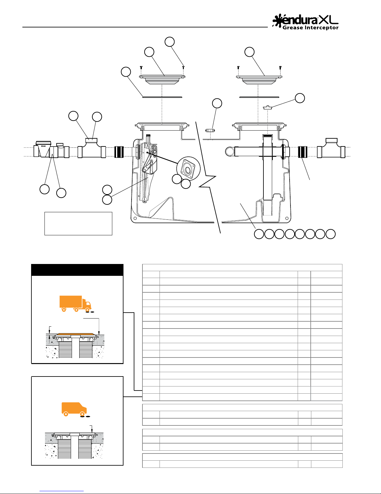
Parts Overview
Endura® XL Tank Components
Item # Description Qty Part #
1 Endura® XL 75gpm tank 4” Spigot connections with S Rated Lids 1
2 Endura® XL 75gpm tank 4” Spigot connections with M Rated Lids 1
3 Endura® XL 75gpm tank 4” Threaded connections with S Rated Lids 1
4 Endura® XL 75gpm tank 4” Threaded connections with M Rated Lids 1
5 Endura® XL 100gpm tank 4” Spigot connections with S Rated Lids 1
6 Endura® XL 100gpm tank 4” Spigot connections with M Rated Lids 1
7 Endura® XL 100gpm tank 4” Threaded connections with S Rated Lids 1
8 Endura® XL 100gpm tank 4” Threaded connections with M Rated Lids 1
9 75gpm Replacement Dynamic Bae Assembly 1
10 100gpm Replacement Dynamic Bae Assembly 1
11 Internal Flow Control Plate - 75gpm 1
12 Internal Flow Control Plate - 100gpm 1
13 Endura® XL Air Balance/Sample Port Cap 1
14 Cover Seal 2
15 Tamper Resistant Cover Fasteners 2
16 Endura® XL Cover - Trac Rated CSA B481.0 Type ‘S’ 2
17 Endura® XL Cover - Pedestrian/Light Trac Rated CSA B481.0 Type ‘M’ 2
External Flow Control - for PDI/ASME Type A applications
18 Endura® XL External Flow Control - 75gpm 1
19 Endura® XL External Flow Control - 100gpm 1
Parts Purchased - Recommended Installation
20 4” 2-Way Cleanout - Sewer x Sewer x DWV 1
21 4” 2-Way Cleanout - Sewer 1
Parts Purchased - Remote Pump Application
22 Remote pump pipe seal (optional) 1
4075A04
4075A04M
4075A04T
4075A04MT
40100A04
40100A04M
40100A04T
40100A04MT
4075ARDB
40100ARDB
4075-21
40100-21
40100-33
40100-4
40100ARSB
40100ARCS
40100ARCM
4044275
40442100
414150BC
414155BC
40100TPS3

Technical Information
External Flow
Control Dimensions
• Flow Control
Connection
Iron Pipe Size
(Solvent weld)
A 6.13”
B 6.84”
C -
• Flow Control
4” h x h
(155.7mm)
(173.7mm)
Pipe by
others
Air Intake can be connected to building
vent system or be independently to the
atmosphere based on local code.
• Air Intake Tee
4” h x h
3.19”
(81mm)
5.04”
(128mm)
2.72”
(69.1mm)
• Air Intake Tee
Specication:
Sample specication clause.
Contractor shall install a Endura® XL Hydromechanical Grease Interceptor (HGI), Part No. 40100A04
4075A04
certied to the current version of PDI G-101, ASME A112.14.3, NSF ES15741 and CSA B481.1. Approved alternate is permissible providing
written compliance to the following is provided and validated. For threaded (FTP) connection sux part number with T
, 4075A04M q (See page 6 table), and rated to 100GPM q 75GPM q (Indicate as Applicable) independently third-party
q
Capacities
• Part Number 4075A04
Endura XL75 Endura XL100
40100A04
4075A04M
40100A04M
US Gallons Per Minute - GPM (L/Sec) 75 (4.74) 100 (6.3)
Min. Grease Capacity - lb (kg) 150 (68.2) 200 (90.8)
Grease Capacity Actual
(ASME A112.14.3) - lb (kg)
†
NSF ES 15741
Average Eciency % (ASME
A112.14.3)
Operating Temperature Capabilities
Cover Load Rating- CSA B481.0
CSA B481.0
Min. Test Load for Approval
Unit Weight (Empty)
Liquid Capacity
Connection size
S 10,000 lb (4536 kg)
M 2000 lb (907 kg)
S 20,000 lb (9072 kg)
M 4000 lb (1814 kg)
†
559 (253)
1058 (480)
>98% >98%
160˚F
(71˚C)
233 lb
(106 kg)
158 gal
(598 L)
(71˚C)
S 10,000 lb (4536 kg)
M 2000 lb (907 kg)
S 20,000 lb (9072 kg)
M 4000 lb (1814 kg)
283 lb
(128 kg)
257 gal
(973 L)
4” 4”
(mechanical joint only)
®
For full CAD, BIM Models
and 3 Part Master Format
CAD BIM SPECS
, 40100A04M q,
q
Specs visit www.arcat.com
Search keyword “endura”
(Tick if required).
q
†
160˚F
Where an internal ow control is desirable and acceptable to the Authority Having Jurisdiction (AHJ), the interceptor shall be rated and
approved to ASME A112.14.3 Type C. The ow control shall be accessible for cleaning and inspection up to the maximum burial depth of
72” regardless of the application and when requiring Riser Extension, the installing contractor will extend the opening device according
to manufacturers published instructions. The outlet system will provide facility for connections to be made perpendicular to the inlet
connection. Connection formats will be compliant with requirements of AHJ and the performance standards identied above. Contractor
shall provide mechanical joint connectors or requisite materials to connect the grease interceptor to the drainage system, additionally
making adequate provision for management of food debris and solids.
Interceptor shall be furnished with two (2) access covers, maximizing internal visibility for inspection and maintenance when removed.
These covers shall be capable of withstanding a proof load of 20,000lbs, approved for application at temperatures from -20˚F to +100˚F
(-29˚C to +38˚C) and will be mechanically secured when operational.
The interceptor tank shall be constructed with seemless engineered thermoplastics, evaluated and approved to the material performance
requirements of CSA B481.0
The interceptor shall additionally; operate with an air-balanced environment to equalize variation in internal pressures being controlled
and maintained with an appropriately sized air balance means; be supported by a Lifetime Warranty against manufacturing defect.
For approved Plumbing & Drainage Institute (PDI) installation, an accessible ow control 40442100A
40442100AT
the interceptor, being vented and installed according to manufactures instructions and the currently published version of PDI G-101.
Interceptor will be located within 25ft developed pipe run of the last connected appliance for standard compliance. Where applicable
a secondary ow control will be employed in installations where there is greater than 8ft of vertical elevation between the kitchen
discharge appliances and the interceptor inlet.
, 4044275AT q (Indicate as applicable) with molded orice and removable access cap will be installed upstream of
q
, 4044275A q
q
- 7 -

Installation Specications
79”
50”
72”
height
Maximum
Native soil
pea gravel or sand
aggregate material
6” Min. base crushed
approx. 3/4" size rock,
95 proctor.
Rebar
Concrete Pad must extend
18" outside the unit footprint
4"
22”
26”
18" outside
must extend
Concrete Pad
the unit footprint
14
45.00°
43”
Rebar
4"
Top View
2 1/2" Min.
29”
Finished Grade
Elevation View
8"
59”
39.5”
DIMENSIONS
32”
Concrete slab
on outlet pipe of each
unit (by others)
Clean out to grade
72”
Maximum
EXCAVATION AND
BACKFILL DETAIL
(INTERIOR OR EXTERIOR)
height
or sand
Flow
Standard 4”
tee (414155BC)
2-Way cleanout
mechnical joint
coupling (by others)
Crushed aggregate
material approximately
3/4" size rock, pea gravel
Endura brand products
manufactured by
Canplas Industries Ltd.
Canplas Industries Ltd.
500 Veterans Drive, Box 1800
Barrie, Ontario,
Canada L4M 4V3
CAN: 1-800-461-1771 USA: 1-888-461-5307
PE
REV: 1.2
4075A04 4075A04T 4075A04M 4075A04MT
DWG NUMBER: XL75BGT
MATL:
DATE: MAY, 2017
DWG BY: L.S.
Risers to grade
mechnical joints
coupling (by others)
SIDE VIEW DETAIL
(Connecting pipe and fittings by others)
For unit details see specification sheet for selected unit
NOTES:
Endura XL grease interceptors are rated and supplied with an internal flow control system already in place.
PROPRIETARY AND CONFIDENTIAL - © Canplas 2017
They do not require an external flow control system or air intake vent unless specified by local code requirements
or being operated as a PDI G-101 installation. Endura XL grease interceptors are only to be installed in the
manner and for the application shown. Consult local codes for separate trapping requirements, cleanout locations
and additional installation instructions. Full instructional information supplied with every interceptor.
DESCRIPTION:
(INTERIOR OR EXTERIOR)
CONCRETE SLAB DETAIL FOR TRAFFIC LOADING
Standard 4”
tee (414155BC)
2-Way cleanout
on inlet pipe of each
Clean out to grade
unit (by others)
Flow
Endura® XL - EXTERIOR BELOW GRADE INSTALLATION INSTRUCTIONS
BELOW GRADE INSTALLATION INSTRUCTIONS
1. EXCAVATION
1.1 Install the Endura ® XL unit(s) as close as possible to xtures being serviced, ideally within 25ft of
developed pipe run from the last xture to the inlet of the interceptor.
1.2 Width and length of excavation shall be minimum 12” greater than the tank dimensions on all sides.
1.3 Depth of excavation shall be at least 6” deeper than tank bottom.
1.4 IMPORTANT: Maximum burial depth 6ft (72”) measured from the air balance channel (EnduraXL Logo)
to nished grade/oor level. Riser extensions available (40100AX35) - (see below).
1.5 Set the tank on well-packed crushed aggregate material approximately 3/4” size rock, pea gravel or
sand. When setting Endura® XL units they must be level laterally and longitudinally.
1.6 Endura® XL tanks are specically designed to resist bouyancy in high water table conditions. Additional
anchoring may however be necessary as determined by the specifying engineer. Tie-down locations are
incorporated to the tank and can be used in conjunction with coated stainless steel cable and an
applicable anchor method based on subsoil. Specific requirements to be determined by specifying engineer.
2. BACKFILLING & FINISHED CONCRETE SLAB (TRAFFIC LOAD RATED)
Endura® XL is supplied standard with trac rated covers designed in accordance with
AASHTO 304 – H20 (16,000lbs) and approved to CSA B481.0 Class ‘S’ -20˚F to +100˚F (-29˚C to +38˚C)
2.1 Preparation of sub grade per local jurisdictional recommendations.
- 8 -
All Endura® XL Grease Interceptors are manufactured with no hub connections. Threaded connections are
2.2 Stabilize and compact sub grade to 95% proctor per Excavation information above.
2.3 Fill tank with water (to discharge level) to prevent movement during backlling process and to resist
backll load.
2.4 Before backlling and pouring of slab, install riser(s) (as necessary) and cover assembly to suit nished
oor/grade level.
2.5 Backll using crushed aggregate material approximately 3/4” size rock, pea gravel or sand.
2.6 Place minimum 6” aggregate base beneath poured structural slab. Aggregate should be 3/4” size rock or
pea shingle.
2.7 Thickness of concrete around cover to be determined by specifying engineer. If trac loading is required
refer to local specifying engineer recommendations and/or local code requirements. Note: Concrete slab
dimensions shown are for illustration purposes only.
2.8 Concrete to be 28 day compressive strength to 4000 PSI. Reinforcement with No.4 rebar (1/2”) grade 60
steel per ASTM A615: connected with tie wire. Rebar to be 2½” from edge of concrete. Rebar spacing
12” grid. 4” spacing around access openings.
3. PIPING CONNECTIONS
3.1
available from your Endura distributor suxing the product code with ‘T’ – i.e. 40100A04T
3.2 Locally approved mechanical joint (MJ) couplings are used to connect the inlet and outlet piping to the
tank. This allows transition to dierent piping materials as required.
3.3 Make system piping connections using locally approved MJ couplings installing to manufacturer’s
instructions. Review all eld-made connections for leaks before backlling begins. Isolate the tank from
the system both up and down stream and ll tank with water, submersing the inlet and outlet fully
below the water level. DO NOT PRESSURE TEST – Risk of serious Injury or Death.
3.4 DO NOT decrease pipe diameter across the unit (i.e. 4 inch inlet, 3 inch outlet). If the piping system
needs to be resized, use appropriate mechanical joint reducers consistent with the direction of ow and
installed in compliance with local code.
4 EX TENSION RISERS (Optional)
4.1 Endura® XL Extension Risers provide a maximum of 35” extension per riser. Based on maximum
installation depth up to a maximum of 72” depth of burial can achieved (see 1.4 above), adding
Extension Risers (or part thereof ) during installation. Risers are cut to length on site to suit installation.
4.2 Remove cover from interceptor. Set aside for use at nished grade/oor level.
4.3 Secure riser to tank (frame remains in place) using xings provided. Ensure seal is correctly located.
4.4 Secure the 1-1/2” adapter tting supplied with the Extension Kit to the thread on the top of the handle
mechanism. Cut and extend a length of 1½” DWV pipe per instructions supplied.
4.5 For custom riser length - measure from tank frame to nished grade/oor level. Subtract 1½”. Cut
cleanly by hand or mechanical means using guide rings molded into the riser to give clean straight cut.
Note - Horizontal surface of cover will be 0.5” above nished oor/grade.
4.6 Fit riser seal provided over the cut edge of the riser and locate frame (supplied) over the seal making
sure it is fully seated. Secure with lag screws provided using the pre-drilled locations in frame.
4.7 Repeat process for additional riser if/as required.
4.8 With frame installed and veried at the correct height, pass the handle extension support over the 1½”
DWV and secure the support to the frame with the screw provided. Solvent weld a 1½” vent tee on top
of the pipe to act as a handle.
4.9 Re-t the original cover(s) provided with the interceptor.
 Loading...