

Page 1

Products Solutions Services
BA01264G/08/EN/04.18
71417593
2018-10-01
Operating Instruction
LT5
Float Level Gauge
0
90 10
20
30
40
50
60
70
80
1
23
4
Page 2

Float level gauge LT5
2 Endress+Hauser
Table of contents
1 Safety instructions . . . . . . . . . . . . . . . . . . . . . . . . . . . . 3
1.1 Designated use . . . . . . . . . . . . . . . . . . . . . . . . . . . . . . . . . 3
1.2 Installation, commissioning, and operation . . . . . . . . . 3
1.3 Operational safety . . . . . . . . . . . . . . . . . . . . . . . . . . . . . . 3
1.4 Notes on safety conventions and symbols . . . . . . . . . . 4
1.5 Symbols for certain types of information . . . . . . . . . . . 4
2 Identification . . . . . . . . . . . . . . . . . . . . . . . . . . . . . . . . . 5
2.1 Device designation . . . . . . . . . . . . . . . . . . . . . . . . . . . . . . 5
2.2 Order information . . . . . . . . . . . . . . . . . . . . . . . . . . . . . . 5
2.3 Scope of delivery . . . . . . . . . . . . . . . . . . . . . . . . . . . . . . . . 6
3 Installation . . . . . . . . . . . . . . . . . . . . . . . . . . . . . . . . . . . 7
3.1 Incoming acceptance, transport, storage . . . . . . . . . . . 7
3.2 Installation location . . . . . . . . . . . . . . . . . . . . . . . . . . . . . 8
3.3 Installation tool . . . . . . . . . . . . . . . . . . . . . . . . . . . . . . . . . 9
3.4 Welding for gauge supporter . . . . . . . . . . . . . . . . . . . . . 10
3.5 Guide pipe . . . . . . . . . . . . . . . . . . . . . . . . . . . . . . . . . . . . 11
3.6 Top anchor, hook and base plate setup location . . . . 13
3.7 Installation condition . . . . . . . . . . . . . . . . . . . . . . . . . . . 14
3.8 Length of measuring tape and wire . . . . . . . . . . . . . . . 19
3.9 Sealing materials for wetting liquid and gas part . . . 21
3.10 Material certificates . . . . . . . . . . . . . . . . . . . . . . . . . . . . 22
3.11 Reference view and order code for installation. . . . . . 23
3.12 Guide wire installation . . . . . . . . . . . . . . . . . . . . . . . . . . 43
3.13 Measuring tape and wire installation . . . . . . . . . . . . . 45
3.14 Liquid sealant for seal pot . . . . . . . . . . . . . . . . . . . . . . . 53
4 Display . . . . . . . . . . . . . . . . . . . . . . . . . . . . . . . . . . . . . 56
4.1 Dial display . . . . . . . . . . . . . . . . . . . . . . . . . . . . . . . . . . . 56
4.2 Counter display . . . . . . . . . . . . . . . . . . . . . . . . . . . . . . . . 57
4.3 Indication adjustment. . . . . . . . . . . . . . . . . . . . . . . . . . . 58
5 Operation . . . . . . . . . . . . . . . . . . . . . . . . . . . . . . . . . . . 63
5.1 Check handle . . . . . . . . . . . . . . . . . . . . . . . . . . . . . . . . . 63
5.2 Hoist unit (LT5-1) . . . . . . . . . . . . . . . . . . . . . . . . . . . . . 64
5.3 Hoist unit (LT5-4/LT5-6) . . . . . . . . . . . . . . . . . . . . . . . . 65
6 Parts replacement . . . . . . . . . . . . . . . . . . . . . . . . . . . 66
6.1 Replacement of O-ring for
transmitter (LT5-4/LT5-6) . . . . . . . . . . . . . . . . . . . . . 66
6.2 Drive check replacement (LT5-4/LT5-6) . . . . . . . . . . .67
7 Maintenance . . . . . . . . . . . . . . . . . . . . . . . . . . . . . . . . 69
7.1 Precaution prior to maintenance . . . . . . . . . . . . . . . . . 69
7.2 Daily inspection . . . . . . . . . . . . . . . . . . . . . . . . . . . . . . . . 70
7.3 Periodical inspection . . . . . . . . . . . . . . . . . . . . . . . . . . . 70
8 Troubleshooting . . . . . . . . . . . . . . . . . . . . . . . . . . . . . 71
8.1 Failure causes and countermeasures . . . . . . . . . . . . . 71
9 Repair . . . . . . . . . . . . . . . . . . . . . . . . . . . . . . . . . . . . . . 72
9.1 General information on repairs . . . . . . . . . . . . . . . . . . 72
9.2 Repairs to Ex-approved devices . . . . . . . . . . . . . . . . . . 72
9.3 Spare parts . . . . . . . . . . . . . . . . . . . . . . . . . . . . . . . . . . . 72
9.4 Endress+Hauser service . . . . . . . . . . . . . . . . . . . . . . . . 72
9.5 Return . . . . . . . . . . . . . . . . . . . . . . . . . . . . . . . . . . . . . . . . 73
9.6 Disposal . . . . . . . . . . . . . . . . . . . . . . . . . . . . . . . . . . . . . . 73
10 Technical data . . . . . . . . . . . . . . . . . . . . . . . . . . . . . . . 74
11 Materials defined by standards . . . . . . . . . . . . . . . . 76
Table of Contents
Page 3

Float level gauge LT5
Endress+Hauser 3
1 Safety instructions
1.1 Designated use
The Float Tank Gauge LT5-1 perform an important role in all areas of industry. Many years of operation in wide variety of applications have proven their reliability. No electrical power is required to perform the measurement. In addition, LT series can be installed easily in your site and can measure the
liquid level accurately, and can be used for the detector of the remote command. Therefore LT series
are best suited for use in the following operations.
• Management of Inventory
• Batch Process
• Management of Process Tank
• Safety Drive of Tanks
1.2 Installation, commissioning, and operation
• Mounting, electrical installation, start-up, and maintenance of the instrument may only be performed by trained personnel authorized by the operator of the facility.
• Personnel must read and understand these installation instructions before performing the procedures.
• The instrument may only be operated by personnel who are authorized and trained by the operator
of the facility. All instructions in this manual must be observed.
• The installer must make sure that the measuring system is correctly wired according to the wiring
diagrams. The measuring system must be grounded.
• Observe all law and regulations applicable and valid for your country and pertaining to the opening
and repairing of electrical devices.
• Always be sure to wear gloves when installing any device.
1.3 Operational safety
Changes or modifications other than those expressly approved by Endress+Hauser
are strictly prohibited. Unauthorized modifications can cause malfunction or dam-
age, resulting in serious injury or death.
WARNING
1 Safety instructions
Page 4
Float level gauge LT5
4 Endress+Hauser
1.4 Notes on safety conventions and symbols
To highlight safety-relevant or alternative operating procedures in this manual, the following conventions have been used, each indicated by a corresponding symbol on the left.
1.5 Symbols for certain types of information
Symbol Meaning
A0011189-EN
DANGER!
This symbol alerts you to a dangerous situation. Failure to avoid this situation will result in
serious or fatal injury.
A0011190-EN
WARNING!
This symbol alerts you to a dangerous situation. Failure to avoid this situation can result in
serious or fatal injury.
A0011191-EN
CAUTION!
This symbol alerts you to a dangerous situation. Failure to avoid this situation can result in
minor or medium injury.
A0011192-EN
NOTICE!
This symbol contains information on procedures and other facts which do not result in
personal injury.
Symbol Meaning
A0011182
Allowed
Indicates procedures, processes or actions that are allowed.
A0011183
Recommendation
Indicates procedures, processes or actions that are recommended.
A0011184
Forbidden
Indicates procedures, processes or actions that are forbidden.
A0011193
Tip
Indicates additional information.
DANGER
WARNING
CAUTION
NOTICE
1 Safety instructions
Page 5
Float level gauge LT5
Endress+Hauser 5
2 Identification
2.1 Device designation
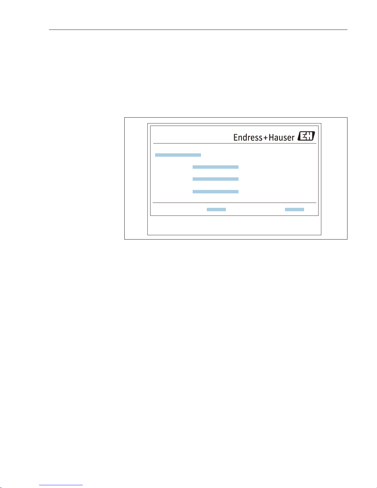
2.1.1 Nameplate
The following technical data are given on the instrument nameplate:
Figure 1: Nameplate
2.2 Order information
Detailed ordering information is available from the following sources:
• In the Product Configurator on the Endress+Hauser website: www.endress.com -> Click "Corporate"
-> Select your country -> Click "Products" -> Select the product using the filters and search field ->
Open product page -> The "Configure" button to the right of the product image opens the Product
configurator.
• From your Endress+Hauser Sales Center: www.addresses.endress.com Product Configurator - the
tool for individual product configuration
• Up-to-the-minute configuration data
• Depending on the device: Direct input of measuring point-specific information such as measuring
range or operating language
• Automatic verification of exclusion criteria
• Automatic creation of the order code and its breakdown in PDF or Excel output format
• Ability to order directly in the Endress+Hauser Online Shop
NP-2700
ᐃࣞࣥࢪ
/Range
〇㐀ᖺ᭶
/Date
ᾮ㠃ィ/Level gauge LT5
ỺὅἛἾἋἡỸἈὊޛషఇࡸ˟ᅈ
Made in Japan
Yamanashi 406-0846
Endress+Hauser Yamanashi Co.,Ltd.
Order code
Serial no.
Ext. ord. cd.
1
2
3
4
5 6
2 Identification
Page 6
Float level gauge LT5
6 Endress+Hauser
2.3 Scope of delivery
It is extremely important to follow the instructions concerning the unpacking, transportation and storage of measuring instruments provided in the chapter "3.1 Incoming Acceptance, Transportation, Storage". Delivered Items vary depending on the product specifications (refer to "3.9 General View of Standard Drawings and Order Codes").
Accompanying documentation:
• Operating Instructions (this manual)
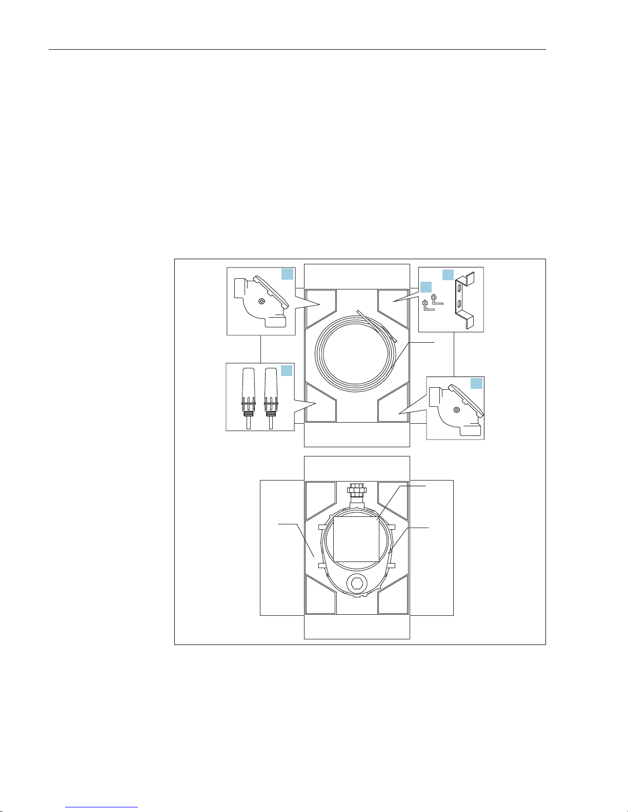
2.3.1 Standard packing layout with carton box
The packing layout and its procedure are vary depending on the order codes.
The flange type of the sheave elbow is delivered separately.
Figure 2: Packing layout
1. Gauge supporter
2. Anchor hook
3. Sheave elbow
4. Top anchor
5. Guide wire
6. Measuring wire
7. Gauge head
8. Float (packed under the gauge head)
1.
2.
3.
3.
4.
6
7
8
5
2 Identification2 Identification
Page 7

Float level gauge LT5
Endress+Hauser 7
3Installation
3.1 Incoming acceptance, transport, storage
3.1.1 Incoming acceptance
Check the packing and contents for any signs of damage.
Check the shipment, and make sure that nothing is missing and that the items match your order.
3.1.2 Transportation
• Follow the safety instructions and conditions of transportation for instruments in excess of 18kg
(40 lbs.).
• Do not lift the measuring instrument by its head (union or flange) during unpacking.
3.1.3 Storage
Pack the measuring instrument so that it is protected against impacts during storage and transportation. The original packing material provides the optimum protection for this.
The allowed storage temperature is -20 to +70 °C.
WARNING
3 Installation
Page 8
Float level gauge LT5
8 Endress+Hauser
3.2 Installation location
Be sure to perform the following operation prior to installation of LT.
• LT series should be installed in a place where meter can be easily read.
• The float must be installed so it is positioned near the tank sidewall.
• In a spherical tank, the float must be installed so that it is positioned in line with the center of the
tank.
• When installing LT on tanks that have a dome roof with a steep incline, the float must be installed
so it is positioned in line with the center of the tank.
• Use an appropriate gasket on flange connection to maintain airtightness.
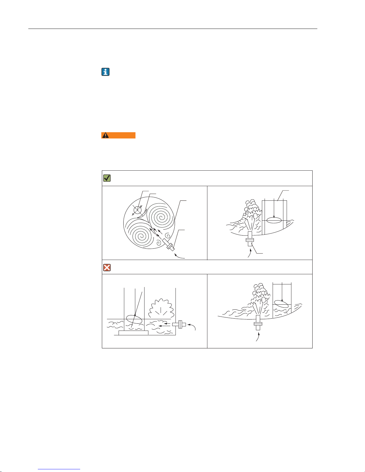
The float should be positioned as far from the tank inlet or stirrer as possible, so that
the waves, which caused by liquid inflow, do not directly impact the float. If there is
no choice but to position the float near an inlet or stirrer, install a wave guard to protect the float. If liquid flows into the tank abruptly, the float line may be severed.
Figure 3: Setup Condition
1. Center of float
2. wave guard
3. Tank
4. Liquid inlet
WARNING
1
2
3
4
2
4
4
4
3 Installation
Page 9
Float level gauge LT5
Endress+Hauser 9
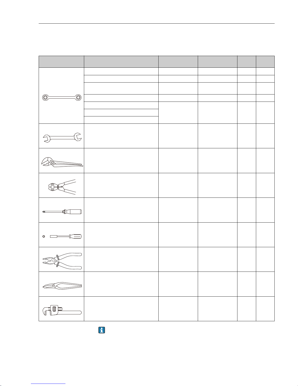
3.3 Installation tool
When installing LT5, prepare the following tools.
Figure 4: Tools to be prepared
● : Use on tank roof
○ : Use at ground level
◎ : Use at both on the tank roof and at ground level
― : Not in use
Tool Usage of tool
LT5-1
(Low/Threaded type
LT5-1
(Low/Threaded type)
LT5-4 LT5-6
Box end wrench
13 mm (0.51 in): Sheave elbow cover removal
●●●-
24 mm (0.94 in): Sheave elbow cover removal
---●
17mm (0.67 in): Gauge head installation
○○○
-
24mm (0.94 in): Gauge head installation
---●
24 mm (0.94 in): JIS flange installation
-◎◎◎
21 mm (0.83 in): 150lbs flange installation
32 mm (1.26 in): 300lbs flange installation
Open end wrench
19mm (0.75 in): Tighten guide wire bolt & nut
of top anchor, compressing tension spring
●●●●
Water pump plier
250 mm or more (9.84 in): Top anchor installation for threaded type
●---
Wire cutter
Cutting trim guide wire for appropriate length
●●●●
Phillips screwdriver
Mounting measuring tape clump tool
Adjusting counter type display
○○-○
Box end driver
5.5 mm (0.22 in): Measuring tape clump
8 mm (0.31 in): Display cover
○○○○
Plier
Tightening measuring clump tool
○○○○
Metal scissors
Cutting trim measuring tape
○○○○
Pipe wrench
600 mm or more (23.62 in): Guide pipe installation
○---
3 Installation
Page 10
Float level gauge LT5
10 Endress+Hauser
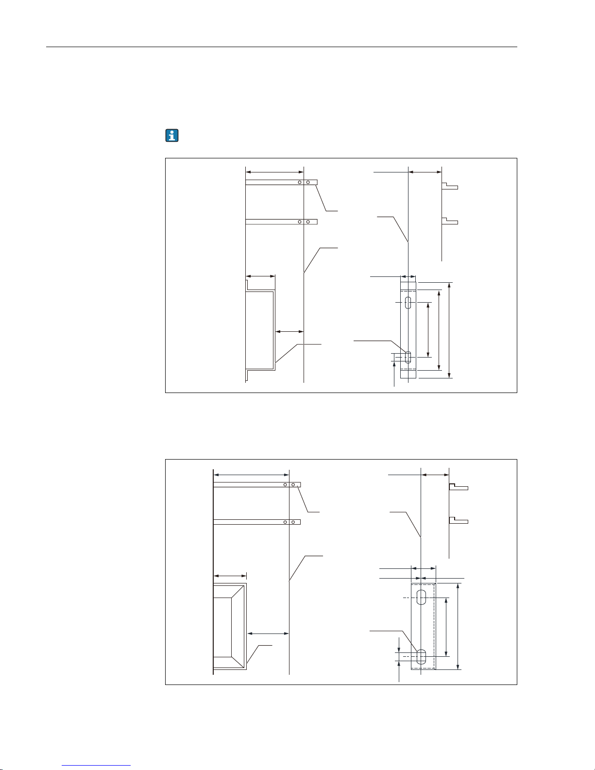
3.4 Welding for gauge supporter
When welding the gauge supporter, refer to the diagram below. Pipe supporter is supplied by th customer.
Distance between outer tank wall and gauge head (LT5-6 for high pressure) is 15 mm greater
than for that of LT5-1 (for low pressure) and LT5-4 (for medium pressure).
Figure 5: Gauge supporter (low and medium pressure) Unit: mm (in)
1. Pipe supporter (supplied by the customer)
2. Center line of mounting position
3. Center line of gauge supporter
4. Gauge supporter (select from SS400: t = 4.5 or SUS304: t = 4.0) with bolts
Figure 6: Gauge supporter (high pressure) Unit: mm (in)
1. Pipe supporter (supplied by the customer)
2. Center line of mounting position
3. Gauge supporter (select from SS400: t = 4.0 or SUS304: t =4.0)with bolts
4. Center line of gauge supporter
32(1.26)
R5.5 (0.22)
25
(0.98)
170±2 (0.7)
250 (9.84)
300 (11.81)
250 (9.84)
160
(6.3)
90
(3.54)
25 (0.98)
1
2
4
3
50 (1.97)
20 (0.79) 30(1.18)
250 (9.84)
170 (0.7)
265 (10.43)
175 (6.89)
90
(3.54)
25 (0.98)
25
(0.98)
R9 (0.35)
1
2
4
3
3 Installation
Page 11
Float level gauge LT5
Endress+Hauser 11
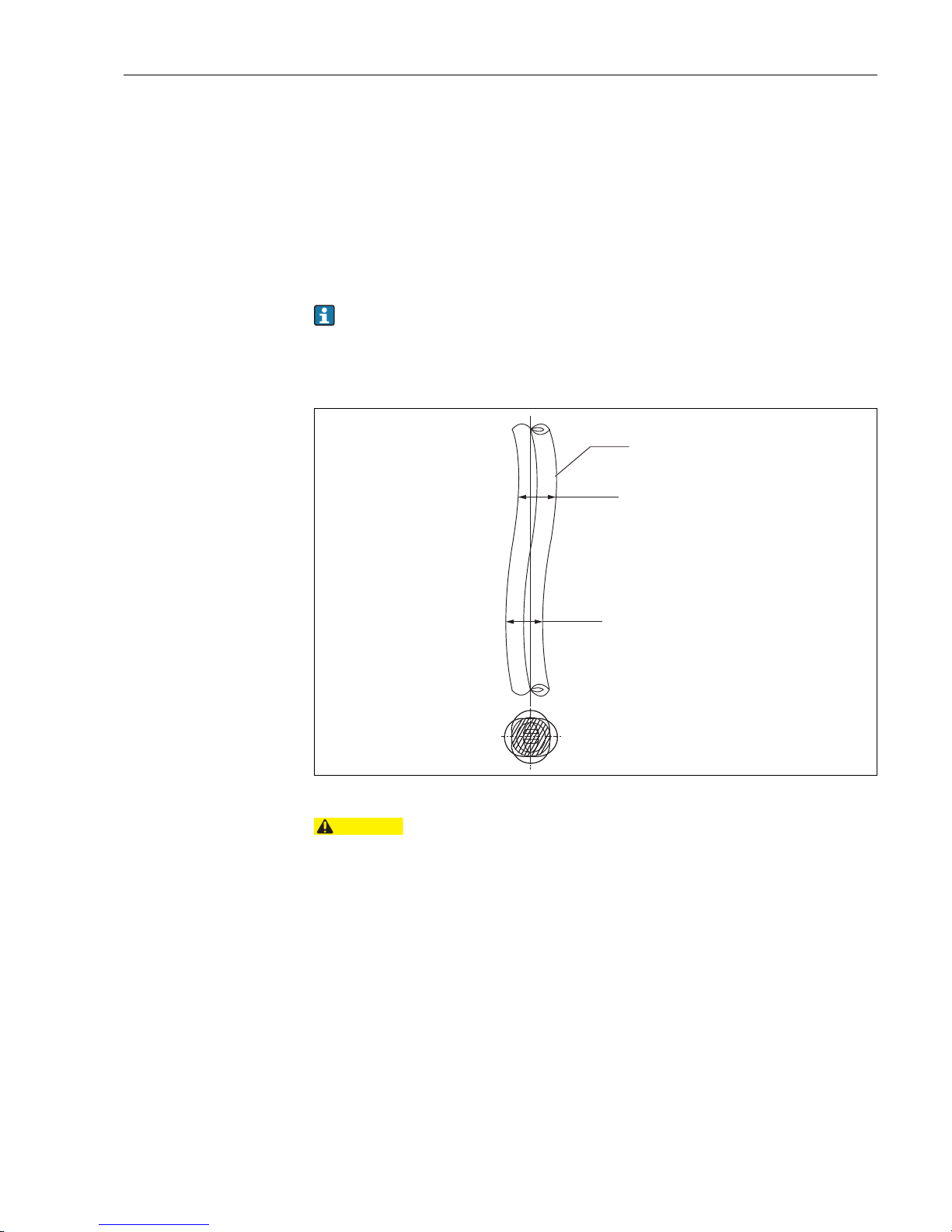
3.5 Guide pipe
3.5.1 Guide pipe material and installation
Most LT installations will require the use of guide pipes, excluding tank top or underground applications. Pipe supporters are generally used in three sections as follows.
• Gauge head to elbow
• Elbow to elbow
• Elbow to tank roof
• The guide pipe and guide pipe supporter must be supplied by the customer.
• Vending of guide pipe must be 5 mm (0.17 in) or less.
• Spacing between the guide and the sheave elbow must be 2500 mm (98.43 in) or less.
Figure 7: Attachment of guide pipe
Galvanized carbon steel pipe is recommended for use as guide pipes.
When application is for extremely corrosive gas, using stainless steel or hard PVC
pipe, containing a resin inner lining is recommended.
1-1/2B
< ± 5 (0.2)
< ± 5 (0.2)
CAUTION
3 Installation
Page 12
Float level gauge LT5
12 Endress+Hauser
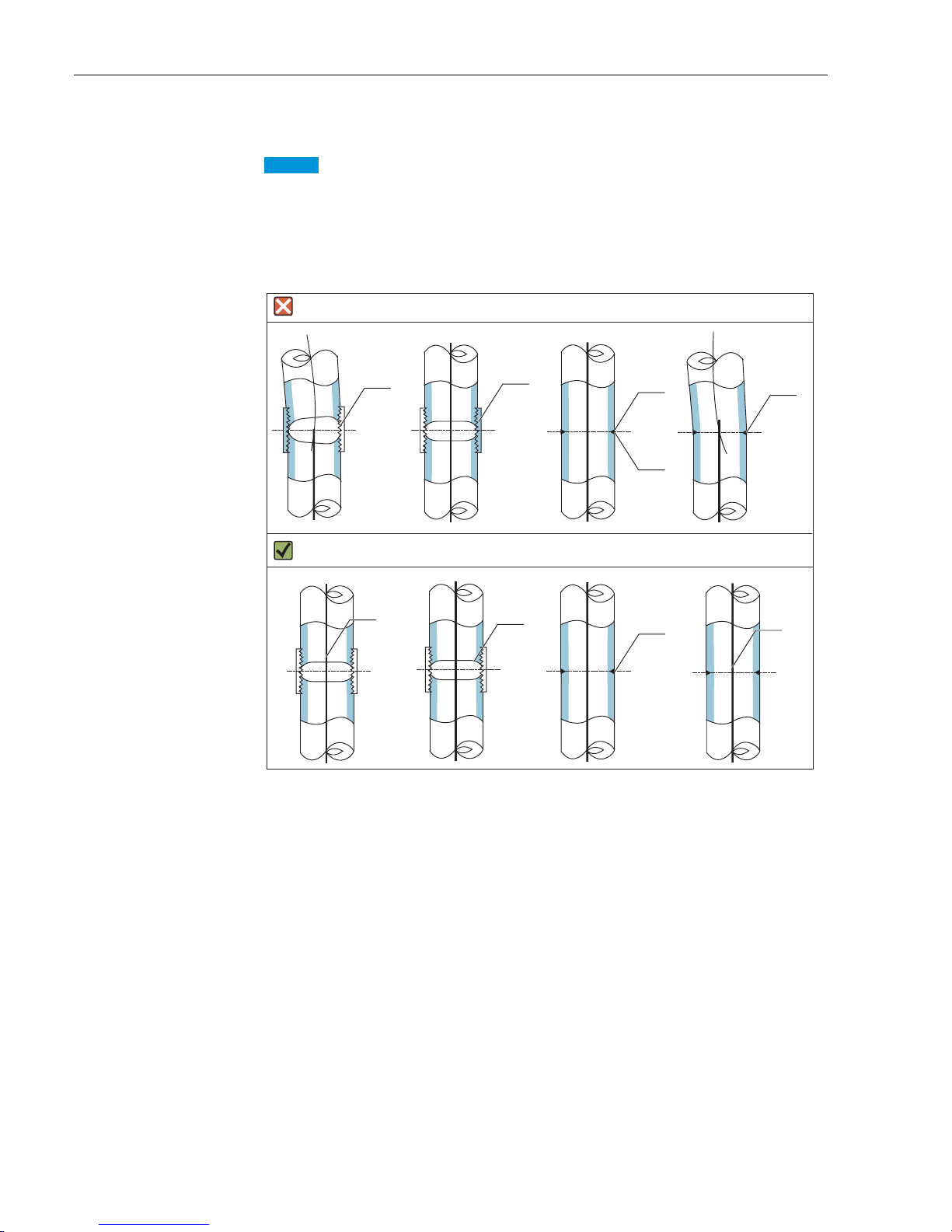
3.5.2 Guide pipe connection
• Use a PTFE sealing tape or gasket to maintain airtightness against gas or rain.
• Be sure connection between the guide pipe and the union is secure so that rain water does not enter
LT5 from the union connection.
• Be sure that threaded connections are properly threaded to avoid a distorted or bent connection,
and be sure that welded connections are straight with no burrs left on the inside.
Figure 8: Guide pipe connection
1. Bending by welding
2. Welding part
3. Welding burr
4. Burr
5. Screw bending
6. Vertical line
7. Remove welding burr
8. Chamfering
NOTICE
1
2
3
4
5
6
7
8
6
3 Installation
Page 13
Float level gauge LT5
Endress+Hauser 13
3.6 Top anchor, hook and base plate setup location
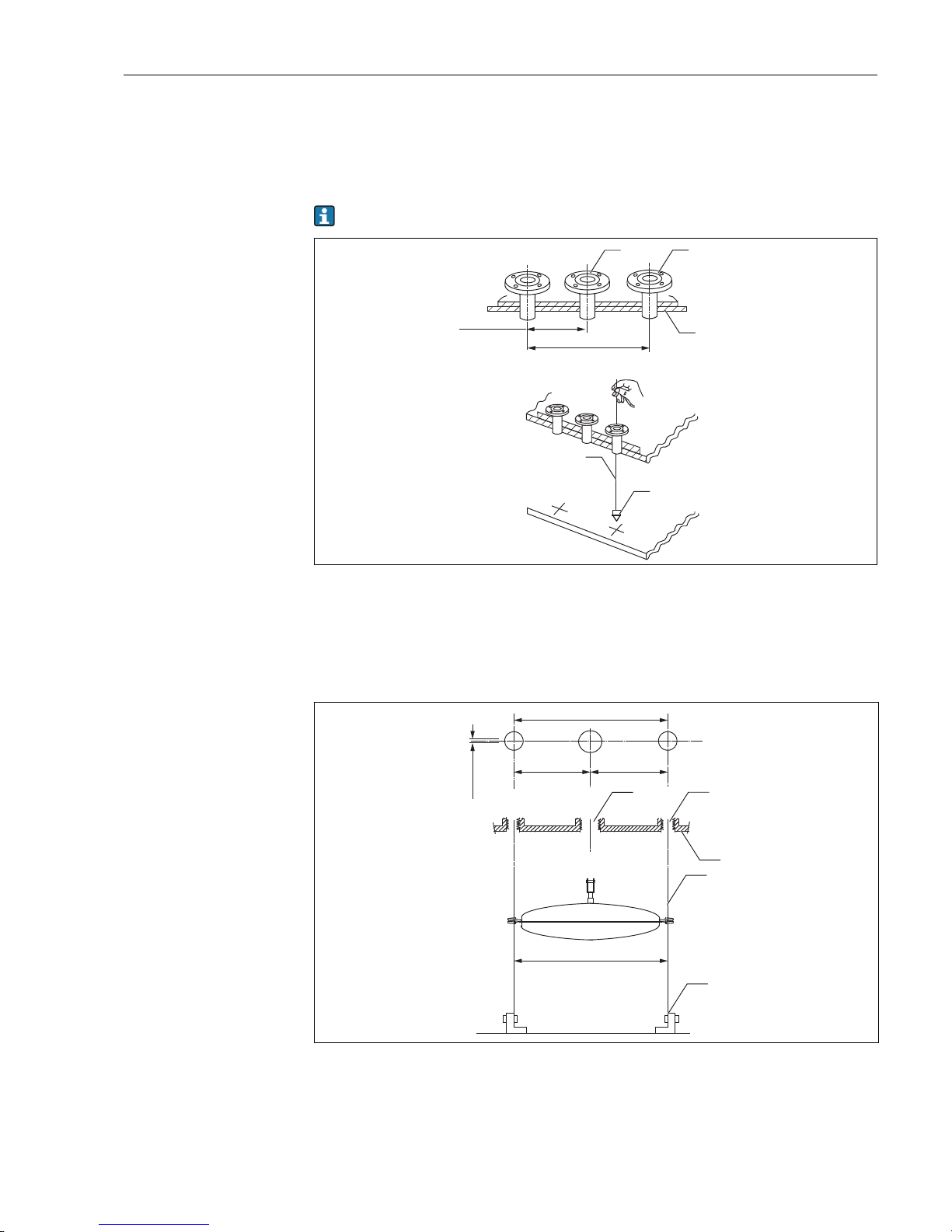
When attaching the anchor hook, take the anchor hook down so that it is positioned vertically against
the top anchor using a plumb.
The flange will be a socket type depending on specifications.
Figure 9: Confirmation for pre-installation of top anchor
1. Nozzle flange for gauge head
2. Nozzle flange for top anchor
3. Tank top
4. Leveling line
5. Plump
Socket (threaded type)
Figure 10: Attachment of anchor hook
1. 1-1/2B socket
2. 1B socket
3. Tank top
4. Guide wire (single wire)
5. Anchor hook
1
2
220 (8.66)
440 (17.32)
3
4
5
±5 (0.2)
220 (8.66)
220 (8.66)
440 (8.66)
440 (8.66)
1
2
4
3
5
3 Installation
Page 14
Float level gauge LT5
14 Endress+Hauser
3.7 Installation condition
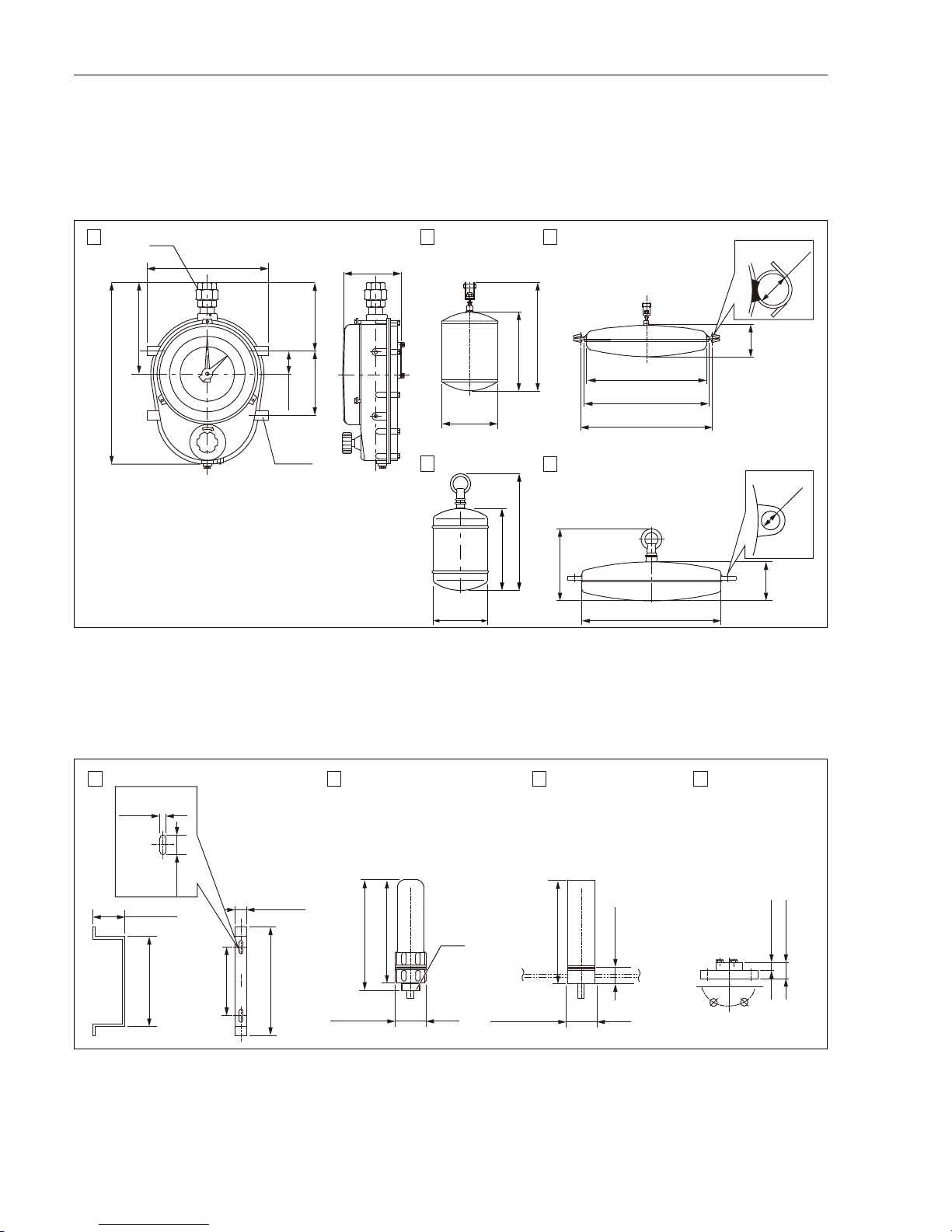
3.7.1 Dimensions of LT5-1 (Threaded type/low pressure)
Figure 11: Dimensions of LT5-1,
float, Unit: mm (in)
A Gauge head (ADC12)
B Float Ø140 (SUS316)
C Float Ø400 (SUS316)
DFloat Ø140 (PVC)
CFloat Ø400 (PVC)
1. Union nut (select from JIS Rc 1-1, 2 /ANSI NPT 1-1/2, or Rp 1-1/2 without union nut)
Figure 12: Accessory, Unit mm (in) A Gauge supporter (select from iron or SUS304)
B Top anchor (ADC6)
C Top anchor (SUS316 with socket welding)
D Top anchor (PVC; flange type only)
1. Tip of the top anchor (select from JIS R1 or ANSI NPT1)
153
(6.02)
200 (7.87)
210 (8.27)
305 (12)
275 (10.82)
Ø140
(5.51)
Ø140
(5.51)
A
B C
1
109
(4.3)
112
(4.41)
Ø400 (15.74)
Ø400 (15.74)
Ø410 (16.14)
440 (17.32)
Ø30
(1.18)
320 (12.6)
60
(2.36)
170 (6.7)
420
(19.3)
240
(9.45)
4-M10
180 (7.1)
D
E
Ø30
(1.18)
207
(8.15)
90 (3.54)
250 (9.84)
32 (1.26)
300 (11.81)
170 (6.69)
170 (6.69)
20 (0.79)
40 (1.57)
216 (8.5)
35 (1.38)
Ø42.7 (1.68)
Ø52 (2.05)
190 (7.48)
36
(1.41)
11
(0.43)
A
B C D
1
3 Installation
Page 15
Float level gauge LT5
Endress+Hauser 15
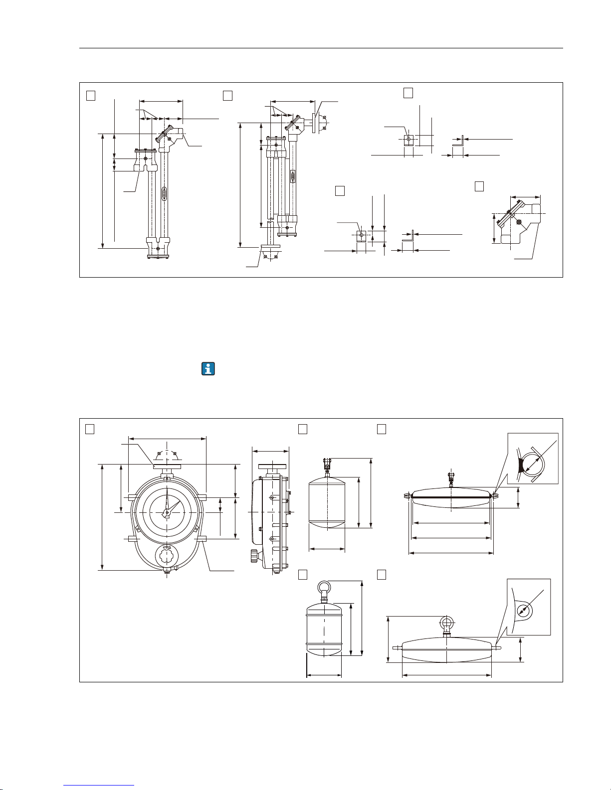
Figure 13: Accessory 2, Unit mm
(in)
A Seal pot (select from aluminum or SUS316)
B Seal pot (PVC; flange type only)
C Anchor hook (select from iron or SUS316)
D Anchor hook (PVC bolt)
E 90° sheave elbow (select from ADC6 or SCS14)
1. Threaded type (select from Rp1-1/2 or NPT1-1/2)
2. Flange (select from JIS 10K 40A FF, ASME NPS1-1/2" Cl.150 FF, or JPI 40A 150 lbs FF)
75 mm (2.95 in) of seal pot shows the dimension of SUS316 spec.
3.7.2 Dimension of LT5-1 (Flange type/low pressure)
Figure 14: Dimensions of LT5-1,
float, Unit: mm (in)
A Gauge head (ADC12)
B Float Ø140 (SUS316)
C Float Ø400 (SUS316)
DFloat Ø140 (PVC)
EFloat Ø400 (PVC)
1. Flange (select from JIS 10K 40A RF, ASME NPS1-1/2" Cl.150 RF, or JPI 40A 150 lbs RF)
A B
C
D
E
*98/75 ( 3.86/2.95)
280 (11.02)
80
(3.15)
80
(3.15)
120 (4.72)
120
(4.72)
120
(4.72)
150 (5.90)
770 (30.31)
1
2
2
330 (12.99)
180
(7.09)
1500 (59.06)
620 (24.4)
Ø13
(0.51)
32 (1.26)
15 (0.6)
40 (1.57)
40 (1.57)
4.5/4
(0.18/0.16))
40 (1.57)
4.5/4
(0.18/0.16))
Ø20
(0.79)
32 (1.26)
25 (0.98)
40 (1.57)
1
1
140
(5.51)
320 (12.6)
153
(6.02)
60
(2.36)
170 (6.7)
450 (17.72)
200
(7.87)
4-M10
A
B
109
(4.3)
Ø400 (15.74)
Ø410 (16.14)
440 (17.32)
Ø30
(1.18)
200 (7.87)
275 (10.82)
Ø140
(5.51)
C
210 (8.27)
305 (12)
Ø140
(5.51)
112
(4.41)
Ø400 (15.74)
D
E
Ø30
(1.18)
207
(8.15)
1
3 Installation
Page 16
Float level gauge LT5
16 Endress+Hauser
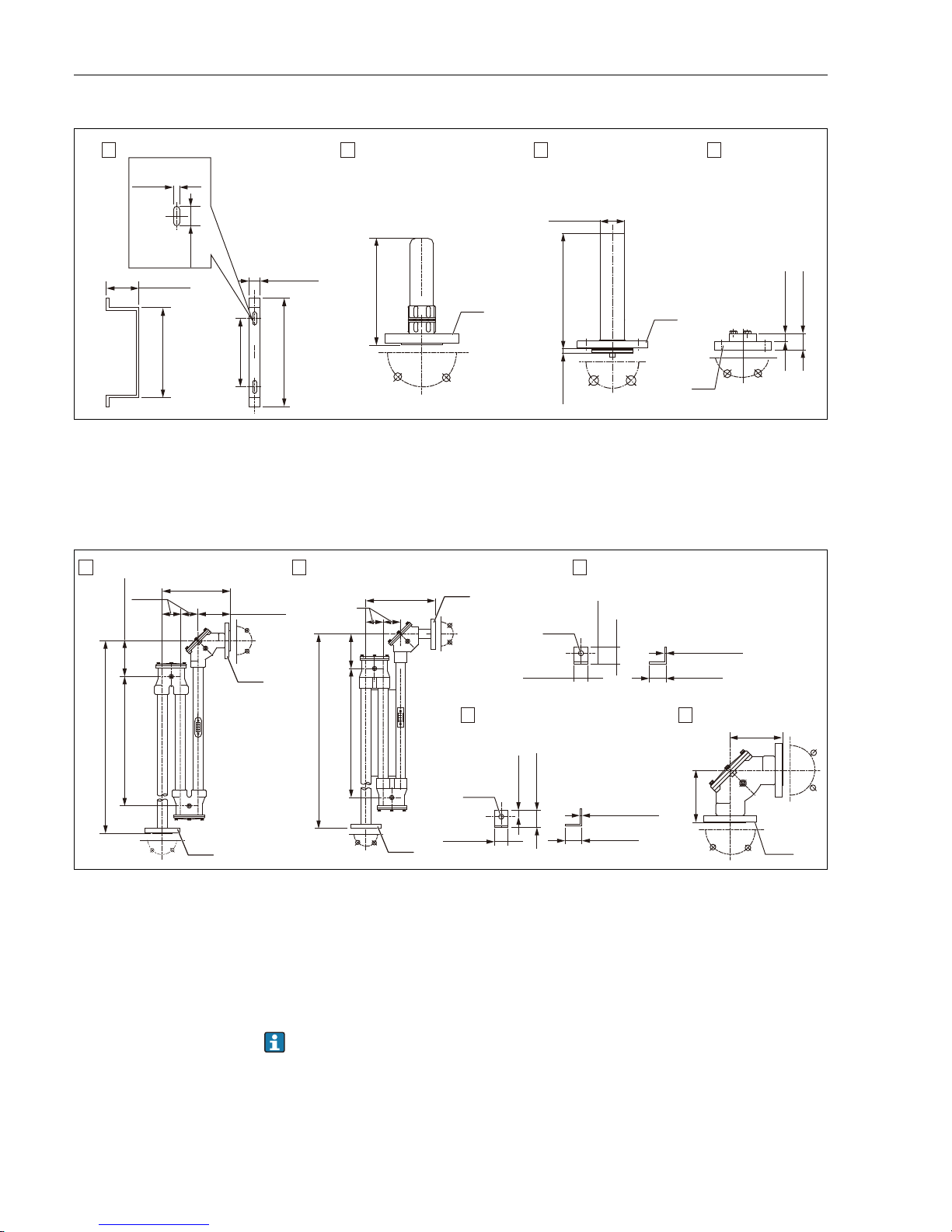
Figure 15: Accessory, Unit mm (in) AGauge supporter
BSocket (ADC6)
C Top anchor (SUS316)
D Top anchor (PVC)
1. Flange (select from JIS 10K 40A RF, ASME NPS 1-1/2" Cl.150 RF, or JPI 40A 150lbs RF)
2. Flange (select from JIS 10K 40A FF, ASME NPS 1-1/2" Cl.150 FF, or JPI 40A 150lbs FF)
Figure 16: Accessory 2, Unit mm
(in)
A Seal pot (select from aluminum or SCS14 + SUS316, see tips below)
BSeal pot (PVC)
C Anchor hook (select from Iron or SUS316)
D Anchor hook (PVC bolt)
E 90° sheave elbow (select from ADC6+AC4A or 5CS14+SUS316)
1. Flange (select from JIS 10K 40A RF, ASME NPS 1-1/2" RF, or JPI 40A 150lbs RF)
2. Flange (select from JIS 10K 40A RF, ASME NPS1-1/2" Cl.150 RF, or JPI 40A 150 lbs RF)
3. Flange (select from JIS 10K 40A FF, ASME NPS1-1/2" Cl.150 FF, or JPI 40A 150 lbs FF)
Tape only: 960 mm (37.8 in)
Tape + wire: 1500 mm (59.06 in)
90 (3.54)
250 (9.84)
32 (1.26)
300 (11.81)
170 (6.69)
20 (0.79)
40 (1.57)
203 (7.99)
36
(1.41)
11
(0.43)
A B C D
1
1
2
230 (9.06)9 (0.35)
49 (1.93)
A B C
D E
300 (11.81)
80
(3.15)
80
(3.15)
140 (5.51)
140
(5.51)
140
(5.51)
150 (5.90)
960 (37.8) *
330 (12.99)
180
(7.09)
1500 (59.06)
620 (24.4)
620 (24.4)
Ø13
(0.51)
32 (1.26)
15 (0.6)
40 (1.57)
40 (1.57)
4.5/4
(0.18/0.16))
40 (1.57)
4
(0.16)
Ø20
(0.79)
32 (1.26)
25 (0.98)
40 (1.57)
1
3
2
2
3
3 Installation
Page 17
Float level gauge LT5
Endress+Hauser 17
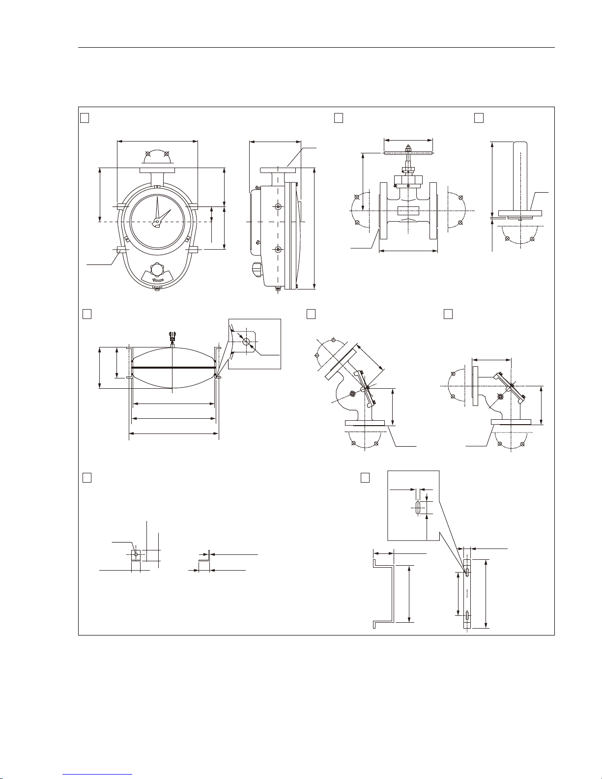
3.7.3 Dimension of LT5-4 (Flange type/medium pressure)
Figure 17: LT5-4, Unit mm (in) AGauge head (AC4CT6)
B Plug gate valve (SCS13)
C Top anchor (AC4CT6)
D Float (SUS316)
E 135° sheave elbow (AC4CT6)
F 90° sheave elbow (AC4CT6)
G Anchor hook (select from iron or SUS316)
H Gauge supporter (select from iron or SUS316)
1. Flange (select from JIS 10K 40A RF, ASME NPS 1-1/2" Cl.150 RF, or JPI 40A 150lbs RF)
232 (9.13)
141 (5.55)
Ø116 (4.57)
<162
(6.38)
9 (0.35)
135 (5.31)
115 (4.53)
115
(4.53)
135 (5.31)
C
Ø13
(0.51)
32 (1.26)
15 (0.6)
40 (1.57)
40 (1.57)
4.5/4
(0.18/0.16))
320 (12.6)
215
(8.46)
60
(2.36)
170 (6.7)
155
(6.10)
4-M10
205
(8.07)
481 (18.94)
A
1
1
11
B
D
G
E F
Ø400 (15.74)
Ø410 (16.14)
440 (17.32)
150
(5.9)
200
(7.87)
Ø20
(0.79)
1
90 (3.54)
250 (9.84)
32 (1.26)
300 (11.81)
170 (6.69)
36
(1.41)
11
(0.43)
H
3 Installation
Page 18

Float level gauge LT5
18 Endress+Hauser
3.7.4 Dimension of LT5-6 (Flange type/high pressure)
Figure 18: LT5-6, Unit mm (in) AGauge head (Iron)
B Plug gate valve (SCS13)
C Top anchor (select from iron or SUS316)
D Float (SUS316)
E 135° sheave elbow (iron)
F 90° sheave elbow (iron)
G Anchor hook (select from iron or SUS316)
H Gauge supporter (select from iron or SUS304)
1 Flange (select from JIS 10K/20K 40A RF, ASME NPS 1-1/2" Cl.150/300 RF, or JPI 40A 150/300lbs. RF)
230 (9.06)
141 (5.55)
Ø116 (4.57)
<162
(6.38)
130 (5.12)
130 (5.12)
130
(5.12)
130 (5.12)
C
A
1
1
11
B
D
E F
Ø400 (15.74)
Ø410 (16.14)
440 (17.32)
150
(5.9)
200
(7.87)
Ø20
(0.79)
H
90 (3.54)
50
(1.97)
9
(0.35)
25 (0.98)
Ø13
(0.51)
32 (1.26)
15 (0.6)
40 (1.57)
40 (1.57)
4.5/4
(0.18/0.16)
G
350 (13.78)
230
(9.06)
60
(2.36)
170 (6.7) 170 (6.7)
4-M16
236
(9.29)
505 (19.88)
1
9 (0.35)
3 Installation
Page 19
Float level gauge LT5
Endress+Hauser 19
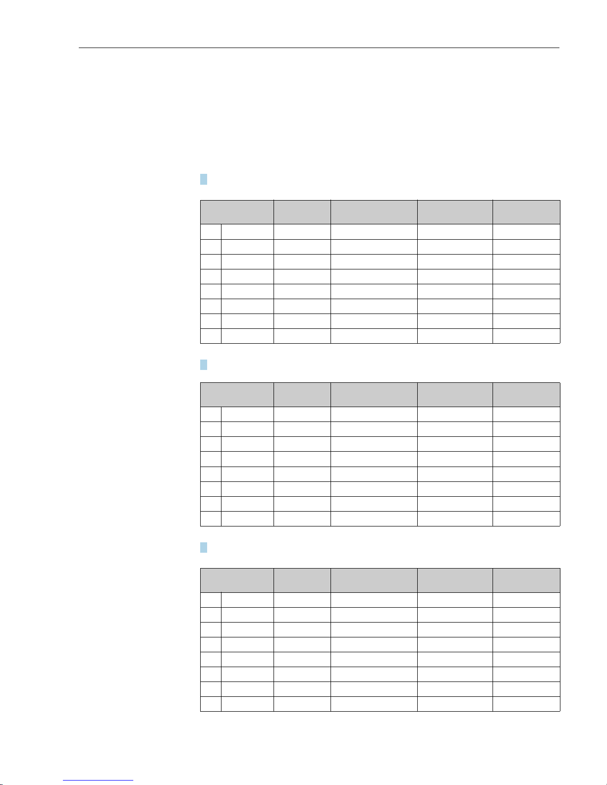
3.8 Length of measuring tape and wire
The lengths of the measuring tape and wire are longer (extra length) than the actual measurement
length and vary depending on each option. The following tables show the actual lengths according to
options in 060 for each option of specification 070. However, note that the maximum length that can
be displayed on the display of the LT5 gauge head simply corresponds to the measurement range. See
the following tables and select the appropriate length accordingly.
In case of Feature 070 is:
1. Measuring tape SUS316, CRT
2. Measuring tape SUS316, tank top installation
3. Measuring tape SUS316, seal pot/BT
060 Measuring
range
Total length Perforated tape
(Measuring length)
Not perforated tape Spare part
1 2.5 m 13 m 7 m 6 m 56004412
2 5 m 13 m 7 m 6 m 56004412
3 10 m 24 m 12 m 12 m 017860-5302
4 16 m 45 m 22 m 23 m 017860-5304
5 20 m 45 m 22 m 23 m 017860-5304
6 30 m 65 m 32 m 33 m 017860-5305
F 60 ft 134.50 ft 68.89 ft 65.61 ft Contact SC in E+H
H 100 ft 216.52 ft 108.26 ft 108.26 ft Contact SC in E+H
060 Measuring
range
Total length Perforated tape
(Measuring length)
Not perforated tape Spare part
1 2.5 m 7.15 m 7 m 0.15 m 017860-5306
2 5 m 7.15 m 7 m 0.15 m 017860-5306
3 10 m 12.15 m 12 m 0.15 m 017860-5307
4 16 m 22.15 m 22 m 0.15 m 017860-5309
5 20 m 22.15 m 22 m 0.15 m 017860-5309
6 30 m 32.15 m 32 m 0.15 m 017860-5310
F 60 ft 72.17 ft 68.89 ft 3.28 ft Contact SC in E+H
H 100 ft 111.54 ft 108.26 ft 3.28 ft Contact SC in E+H
060 Measuring
range
Total length Perforated tape
(Measuring length)
Not perforated tape Spare part
1 2.5 m 24 m 7 m 17 m Contact SC in E+H
2 5 m 24 m 7 m 17 m Contact SC in E+H
3 10 m 35 m 12 m 23 m Contact SC in E+H
4 16 m 55 m 22 m 33 m Contact SC in E+H
5 20 m 55 m 22 m 33 m Contact SC in E+H
6 30 m 75 m 32 m 43 m 017860-5210
F 60 ft 167.31 ft 68.89 ft 98.42 ft Contact SC in E+H
H 100 ft 249.33 ft 108.26 ft 141.07 ft Contact SC in E+H
3 Installation
Page 20
Float level gauge LT5
20 Endress+Hauser
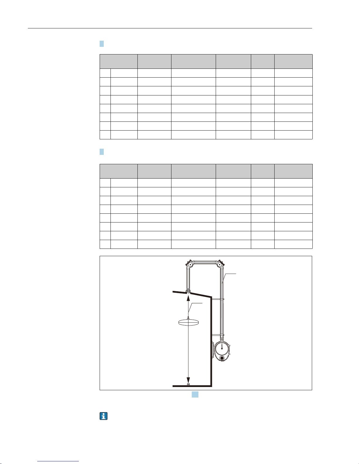
4. Measuring tape SUS316 + wire SUS316, FRT
5. Measuring tape SUS316 + PFA coated SUS316 wire, seal pot/CRT
Figure 19: Measuring tape and wire (e.g. Option in 070 and Option 5 in 060)
1. Perforated tape
2. Not perforated tape/wire
In Figure19, the maximum measuring distance is 22 m and the maximum space for piping is
23 m. Thus, the total length of measuring tape is 45 m.
060 Measuring
range
Total length
tape+wire
Perforated tape
(measuring length)
Not perforated
tape
Wire Spare part
1 2.5 m 16 m 6.7 m 0.3 m 9 m 017860-0005
2 5 m 16 m 6.7 m 0.3 m 9 m 017860-0005
3 10 m 26 m 11.7 m 0.3 m 14 m 017860-0007
4 16 m 46 m 21.7 m 0.3 m 24 m 017860-0011
5 20 m 46 m 21.7 m 0.3 m 24 m 017860-0011
6 30 m 66 m 31.7 m 0.3 m 34 m 017860-0013
F 60 ft 147.63 ft 67.91 ft 0.98 ft 78.74 ft Contact SC in E+H
H 100 ft 219.80 ft 107.28 ft 0.98 ft 111.54 ft Contact SC in E+H
060 Measuring
range
Total length
tape+wire
Perforated tape
(measuring length)
Not perforated
tape
Wire Spare part
12.5 m 18 m 6.7 m 0.3 m 11 m 017860-0006
25 m 18 m 6.7 m 0.3 m 11 m 017860-0006
310 m 28 m 11.7 m 0.3 m 16 m 017860-0008
416 m 48 m 21.7 m 0.3 m 26 m 017860-0012
520 m 48 m 21.7 m 0.3 m 26 m 017860-0012
630 m 68 m 31.7 m 0.3 m 36 m 017860-0014
F60 ft 154.19 ft 67.91 ft 0.98 ft 85.30 ft Contact SC in E+H
H 100 ft 226.37 ft 107.28 ft 0.98 ft 118.11 ft Contact SC in E+H
1
2
1.
3 Installation
Page 21
Float level gauge LT5
Endress+Hauser 21
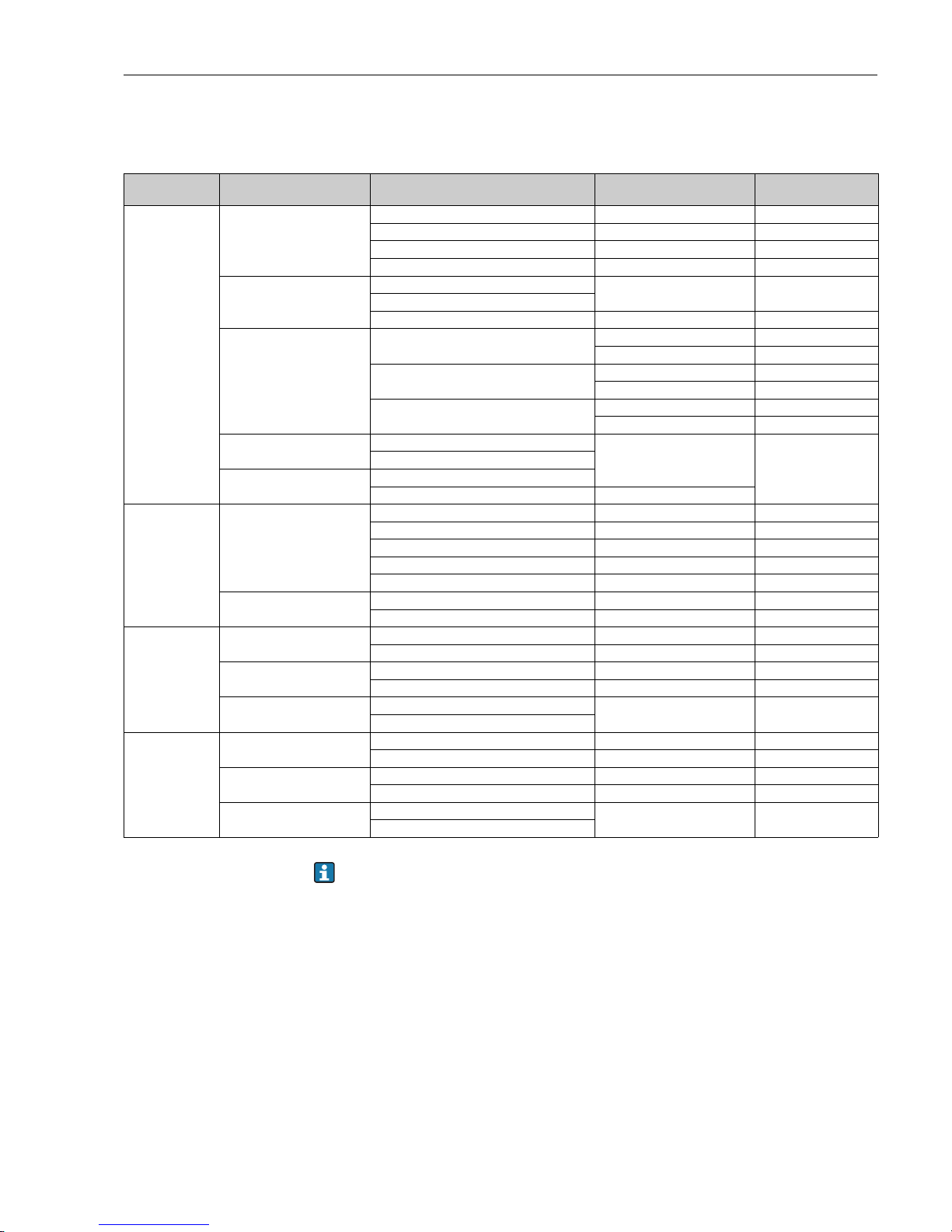
3.9 Sealing materials for wetting liquid and gas part
When selecting the copper free, the material of o-ring is CR.
Product Unit Part name Name of sealing part
Material of packing/
O-ring
LT5-1
Gauge Head
Rear Cover Rear Packing V#6502
Check Shaft O-ring FKM
Sprocket Shaft Oil Seal FKM
Blind Board Packing NBR
90° Sheave Elbow
Aluminum Sheave Elbow
Rear Packing V#6502
Stainless Steel Sheave Elbow
Bearing O-ring Silicon Rubber
Liquid Seal Unit
Aluminum Sheave Elbow
Rear Packing V#6502
Bearing O-ring Silicon Rubber
Stainless Steel Sheave Elbow
Rear Packing V#6502
Bearing O-ring Silicon Rubber
PVC Sheave Elbow
Rear Packing V#6502
Bearing O-ring PTFE
Top Anchor
Aluminum Threaded Type
Rear Packing
V#6502
Stainless Tank Welding Type
Top Anchor
Aluminum Flange/Threaded Type
Stainless Flange Welding Type Spring Negator Packing
LT5-4/LT5-6
Gauge Head
Rear Cover Rear Packing PTFE
Check Handle Gland Packing PTFE/CR
Internal Magnet Cover O-ring PTFE
External Magnet Cover O-ring NBR (see tips below.)
Coupling O-ring PTFE
Gate Valve
Shaft Shaft Packing PTFE
Cap Nut Packing PTFE
LT5-4
90° Sheave Elbow
Cover Rear Packing PTFE
Bearing O-ring PTFE
135° Sheave Elbow
Cover Rear Packing PTFE
Bearing O-ring PTFE
Top Anchor
Flange Integral Pattern
Spring Negator Packing PTFE
Stainless Flange Welding Type
LT5-6
90° Sheave Elbow
Cover Rear Packing PTFE
Bearing O-ring PTFE
135°Sheave Elbow
Cover Rear Packing PTFE
Bearing O-ring PTFE
Top Anchor
Rolled Steel Flange Welding Type
Spring Negator Packing PTFE
Stainless Flange Welding Type
3 Installation
Page 22

Float level gauge LT5
22 Endress+Hauser
3.10 Material certificates
When material certificates are required, please order them when ordering the products. Certificates
can be provided for the following parts.
• High-pressure specification iron gauge head (the certificate for the flange is same as the gauge head
due to integrated casting with the gauge head), cover, magnet cover, check shaft (only for without
hoisting), plug
• Stainless steel measuring tape and wire (excluding PFA coated wire.)
• Stainless steel float
• Stainless steel or high-pressure specification iron top anchor, cover, flange
• Stainless steel guide wire (excluding PFA coated wire)
• Stainless steel anchor hook
• High-pressure specification iron sheave elbow (the certificate for the flange is same as the sheave
elbow due to integrated casting with the sheave elbow), cover
• Stainless steel plug gate valve
Certificates cannot be issued for parts not listed above
3 Installation
Page 23
Float level gauge LT5
Endress+Hauser 23
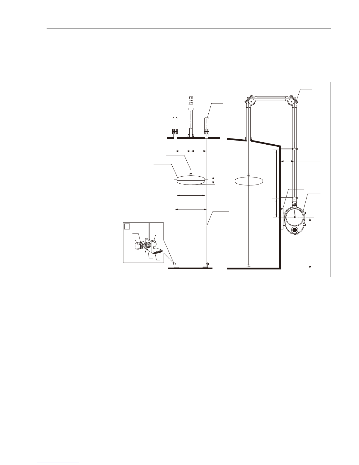
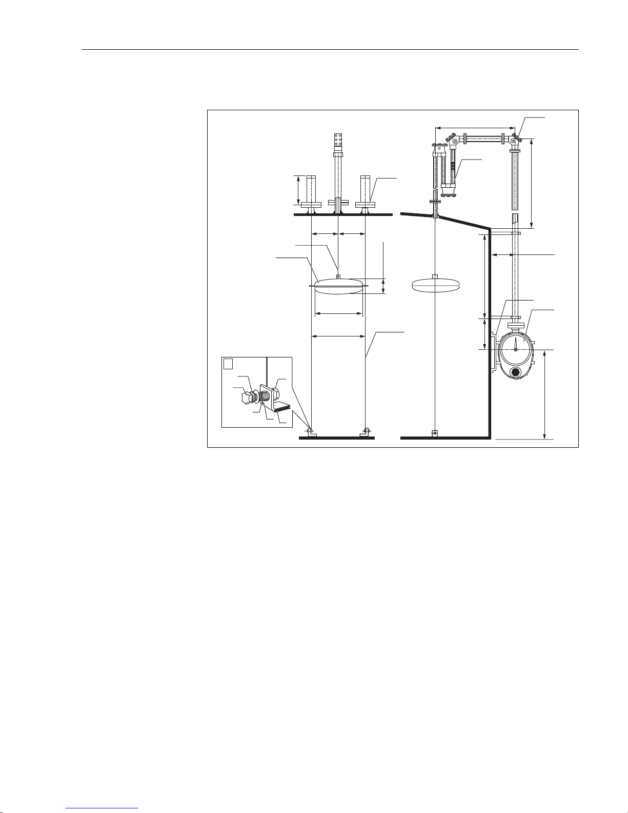
3.11 Reference view and order code for installation
3.11.1 Cone roof tank (CRT)
Figure 20: Cone roof tank (CRT), Unit mm (in)
A Anchor hook
1. Top anchor
2. Measuring tape
3. float
4. Guide wire
5. Nut
6. Wetting part (wetting to the tank)
7. Anchor hook
8. Guide wire
9. Bolt
10. Washer
11. 90° sheaves elbow
12. Gauge supporter
13. Gauge head
220
(8.66)
250 (9.84)
2000 - 3000
(78.74 - 118.11)
300
(11.81)
109 (4.29)
440
(17.32)
Ø400
(15.74)
1200
(47.24)
220
(8.66)
A
1
2
3
4
5
6
7
8
9
10
11
12
13
3 Installation
Page 24
Float level gauge LT5
24 Endress+Hauser
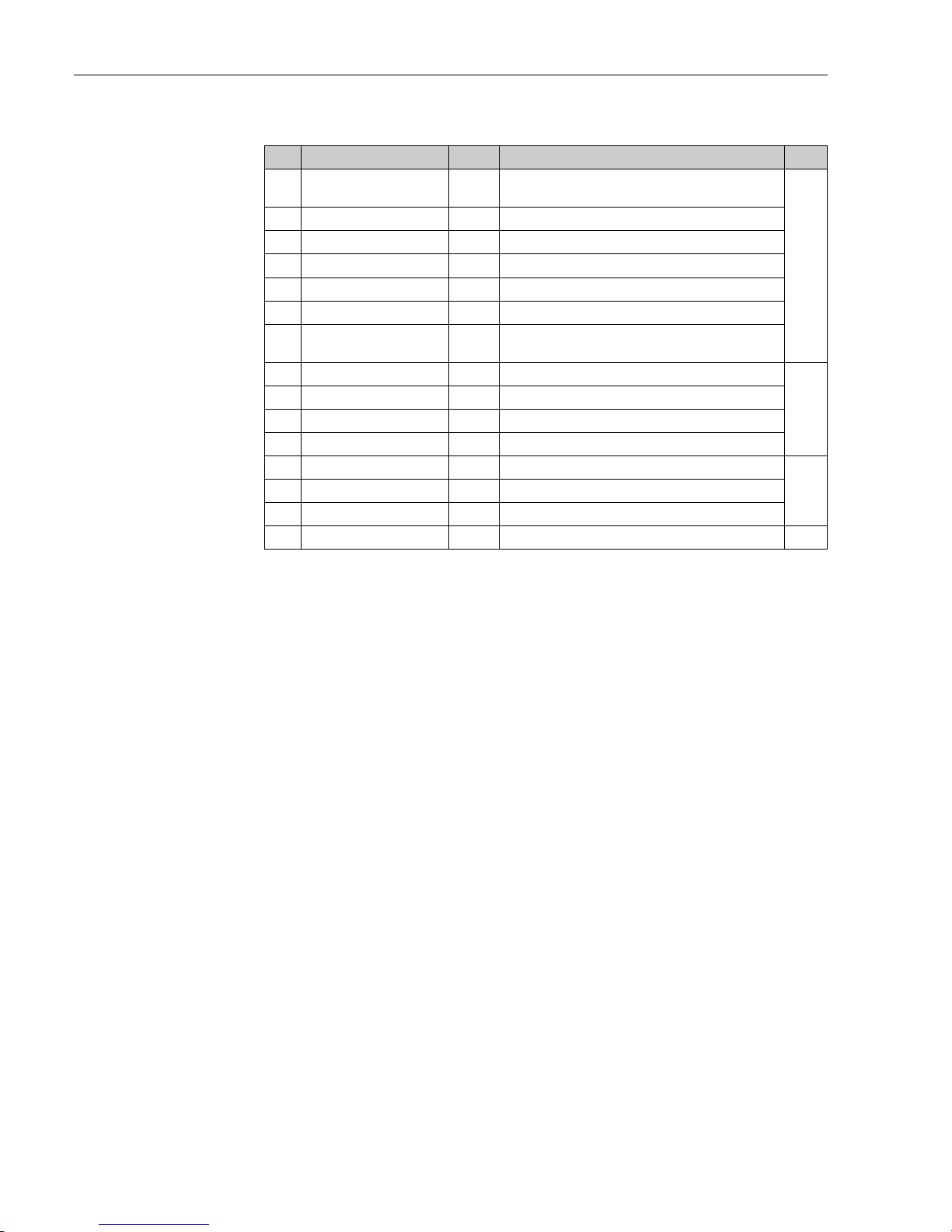
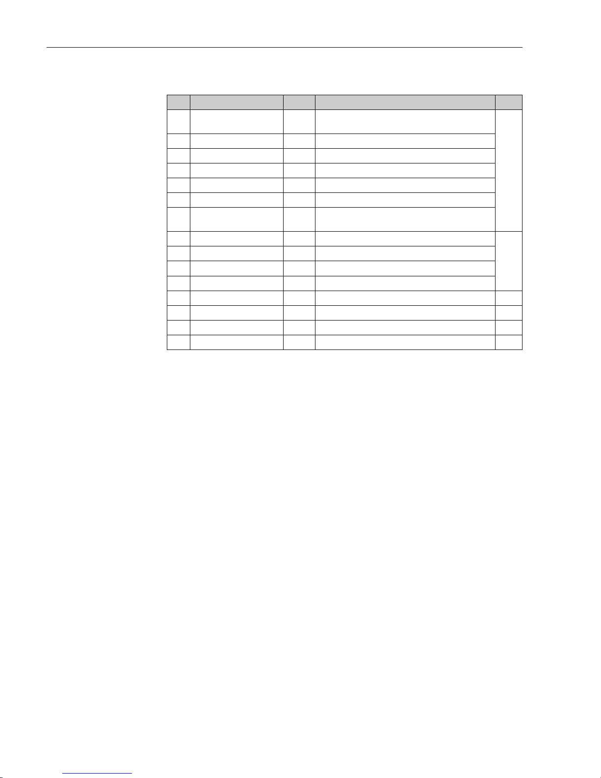
Order code (LT5-111A031B11A111200000+PA)
Feat. Feature text Option Option text Qty.
020 Gauge head 1
0...0.1961bar/0.01961MPa/2.84psi,
Alu (ADC12), Low pressure
1
030 Gauge head connection 11A Rc 1-1/2, union nut, SUS316, thread JIS B0203
040 Display; cover A Dial display; Acrylic
050 Crank unit 0 Not selected
060 Measuring range 3 10 m
070 Measuring tape 1 Measuring tape, CRT
080 Float B
D400mm SUS316 tape connection 5.0kg,
density range >= 0.65...< 1.05, rings
090 Top anchor 11 2x R1, Alu (ADC6), thread JIS B0203
2
100 Guide wire A Diameter 3mm solid wire
110 Bottom anchor; fixing bolt 1 Iron; SUS316
120 90 degree sheave elbow 112 2x Rp1-1/2, Alu (ADC6), thread JIS B0203
130 135 degree sheave elbow 000 Not selected
0140 Seal pot 0 Not selected
150 Valve 0 Not selected
620 >>Accessory enclosed PA Gauge support, Iron 1
3 Installation
Page 25
Float level gauge LT5
Endress+Hauser 25
3.11.2 Tank top for underground tank
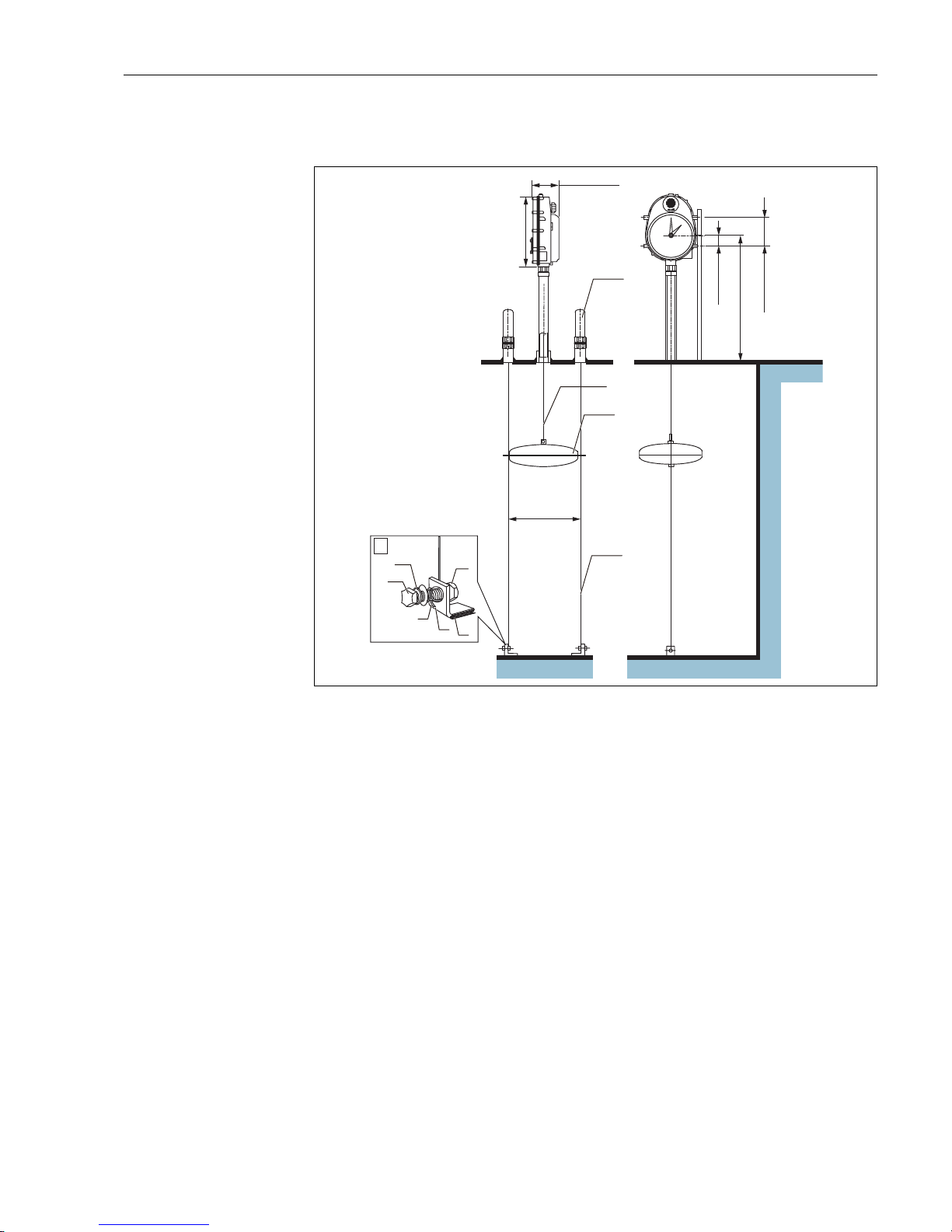
Figure 21: Underground tank, Unit mm (in)
A Anchor hook
1. Top anchor
2. Measuring tape
3. float
4. Guide wire
5. Nut
6. Wetting part (wetting to the tank)
7. Anchor hook
8. Guide wire
9. Bolt
10. Washer
153
417
60 (2.36)
170 (6.69)
A
5
6
7
8
9
10
1200 (47.24)
440
(17.32)
1
2
3
4
3 Installation
Page 26
Float level gauge LT5
26 Endress+Hauser
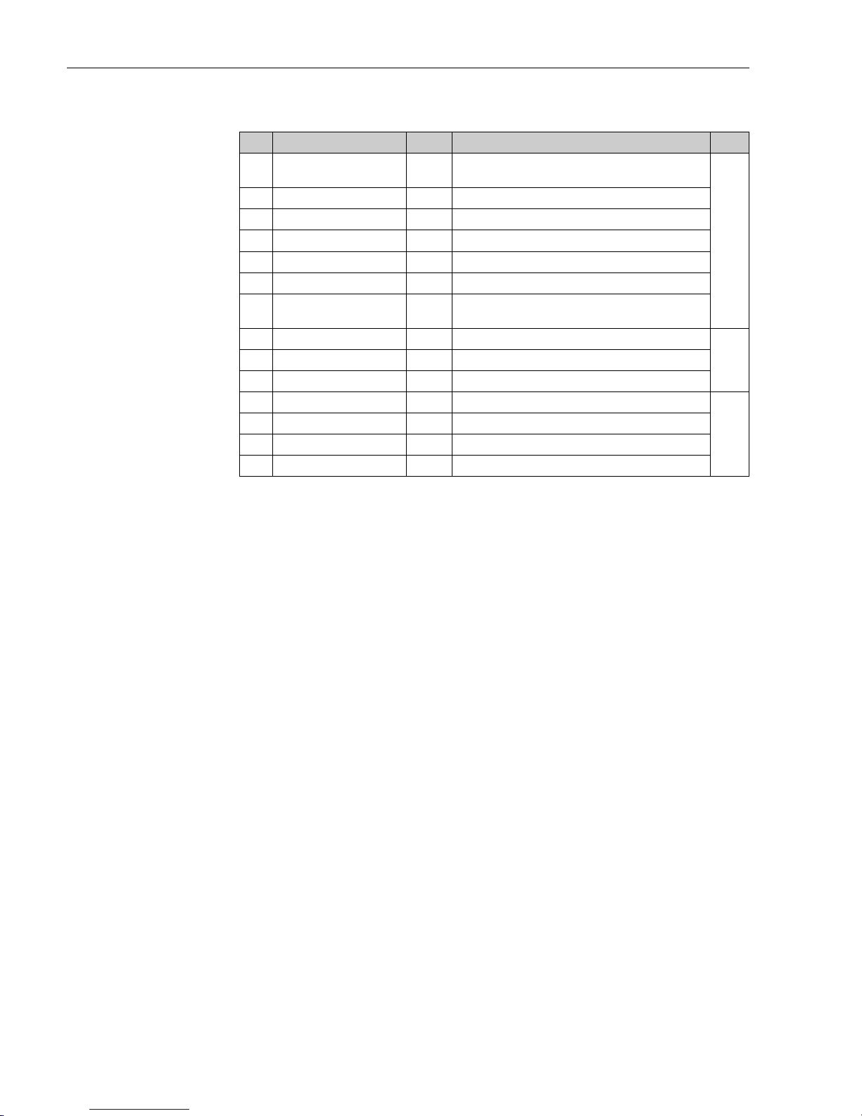
Order code (LT5-111C022B11A100000000)
Feat. Feature text Option Option text Qty.
020 Gauge head 1
0...0.1961bar/0.01961MPa/2.84psi,
Alu (ADC12), Low pressure
1
030 Gauge head connection 11 Rc 1-1/2, union nut, SUS316, thread JIS B0203
040 Display; cover C Dial display upside down; Glass + Iron
050 Crank unit 0 Not selected
060 Measuring range 2 5 m
070 Measuring tape 2 Measuring tape, tank top installation
080 Float B
D400mm SUS316 tape connection 5.0kg,
density range >= 0.65...< 1.05, rings
090 Top anchor 11 2x R1, Alu (ADC6), thread JIS B0203
2100 Guide wire A Diameter 3mm solid wire
110 Bottom anchor; fixing bolt 1 Iron; SUS316
120 90 degree sheave elbow 000 Not selected
0
130 135 degree sheave elbow 000 Not selected
140 Seal pot 0 Not selected
150 Valve 0 Not selected
3 Installation
Page 27
Float level gauge LT5
Endress+Hauser 27
3.11.3 Cone roof tank with seal pot
Figure 22: Cone roof tank with seal pot
A Anchor hook
1. Top anchor
2. Measuring tape
3. float
4. Guide wire
5. Nut
6. Wetting part (wetting to the tank)
7. Anchor hook
8. Guide wire
9. Bolt
10. Washer
11. Seal pot
12. 90° sheaves elbow
13. Gauge supporter
14. Gauge head
230
(9.06)
950 (37.4)
A
5
6
7
8
9
10
440
(17.32)
220
(8.66)
220
(8.66)
250 (9.84)
2000 - 3000
(78.74 - 118.11)
300
(11.81)
109 (4.29)
Ø400
(15.74)
1200 (47.24)
1200 (472.4)
1
2
3
4
11
12
13
14
3 Installation
Page 28
Float level gauge LT5
28 Endress+Hauser
Order code (LT5-11AA023B1BA21A1000F0+PA)
Feat. Feature text Option Option text Qty.
020 Gauge head 1
0...0.1961bar/0.01961MPa/2.84psi,
Alu (ADC12), Low pressure
1
030 Gauge head connection 1A 10K 40A RF, Alu (AC4A), flange JIS B2220
040 Display; cover A Dial display; Acrylic
050 Crank unit 0 Not selected
060 Measuring range 2 5 m
070 Measuring tape 3 Measuring tape, seal pot/BT
080 Float B
D400mm SUS316 tape connection 5.0kg,
density range >= 0.65...< 1.05, rings
090 Top anchor 1B 2x 10K 40A RF, SUS316, flange JIS B2220
2
100 Guide wire A Diameter 3mm solid wire
110 Bottom anchor; fixing bolt 2 SUS316; SUS316
120 90 degree sheave elbow 1A1 1x 10K 40A RF, Alu (ADC6+AC4A), flange JIS B2220
130 135 degree sheave elbow 000 Not selected 0
140 Seal pot F 10K 40A RF, SUS316, flange JIS B2220 1
150 Valve 0 Not selected 0
620 >>Accessory enclosed PA Gauge support, Iron 1
3 Installation
Page 29
Float level gauge LT5
Endress+Hauser 29
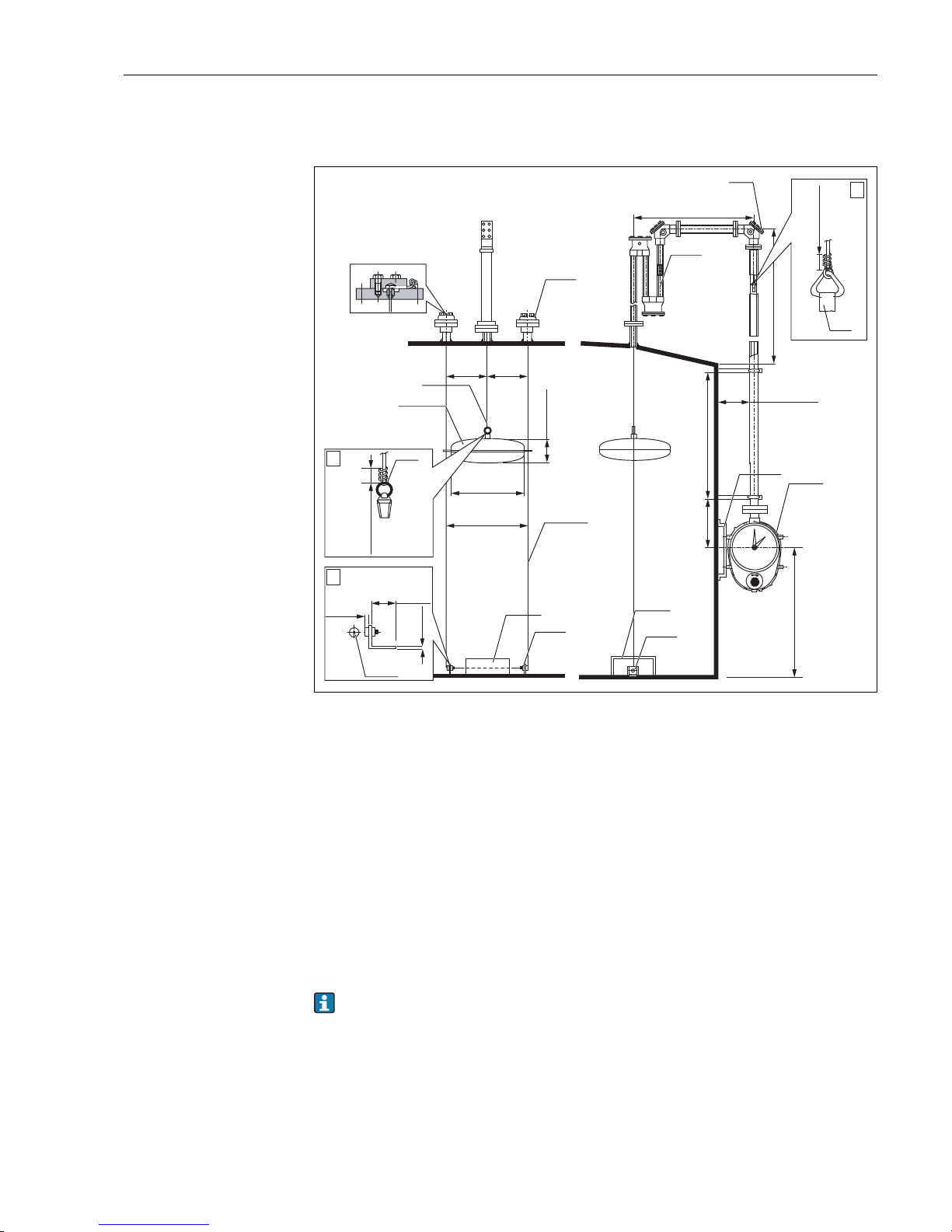
3.11.4 Cone roof tank with seal pot PVC
Figure 23: Cone roof tank with seal pot PVC
A Tip of the float
B Details of anchor hook
C Metal triangle fittings for measuring wire
1. Top anchor
2. Measuring tape
3. float
4. Teflon-coted tube
5. Guide wire (PFA-coated)
6. Guide wire protector (supplied by the customer)
7. Anchor hook
8. 90° sheaves elbow
9. Seal pot
10. Measuring tape
11. Gauge supporter
12. Gauge head
• Bind the provided teflon-coted tube to the measuring wire ten to fifteen times.
• Coat (lining) the anchor hook if necessary.
• Set the position of the joint part C in figure 22 to be approximately level 10 mm (03.93 in) below
the sheave elbow when the liquid level is zero and approximately 100 mm (3.93 in) above the gauge
head when liquid is full.
950 (37.4)
440
(17.32)
220
(8.66)
220
(8.66)
250 (9.84)
2000 - 3000
(78.74 - 118.11)
300
(11.81)
112 (4.4)
Ø400
(15.74)
1200 (47.24)
< 1800 (70.84)
1
2
3
12
5
10
6
6
7
7
8
9
11
7
(0.28)
40
(1.57)
4.5
(0.18)
Ø6
(0.24)
A
B
C
4
30 - 40
(1.18 - 1.57)
30 - 40
(1.18 - 1.57)
3 Installation
Page 30
Float level gauge LT5
30 Endress+Hauser
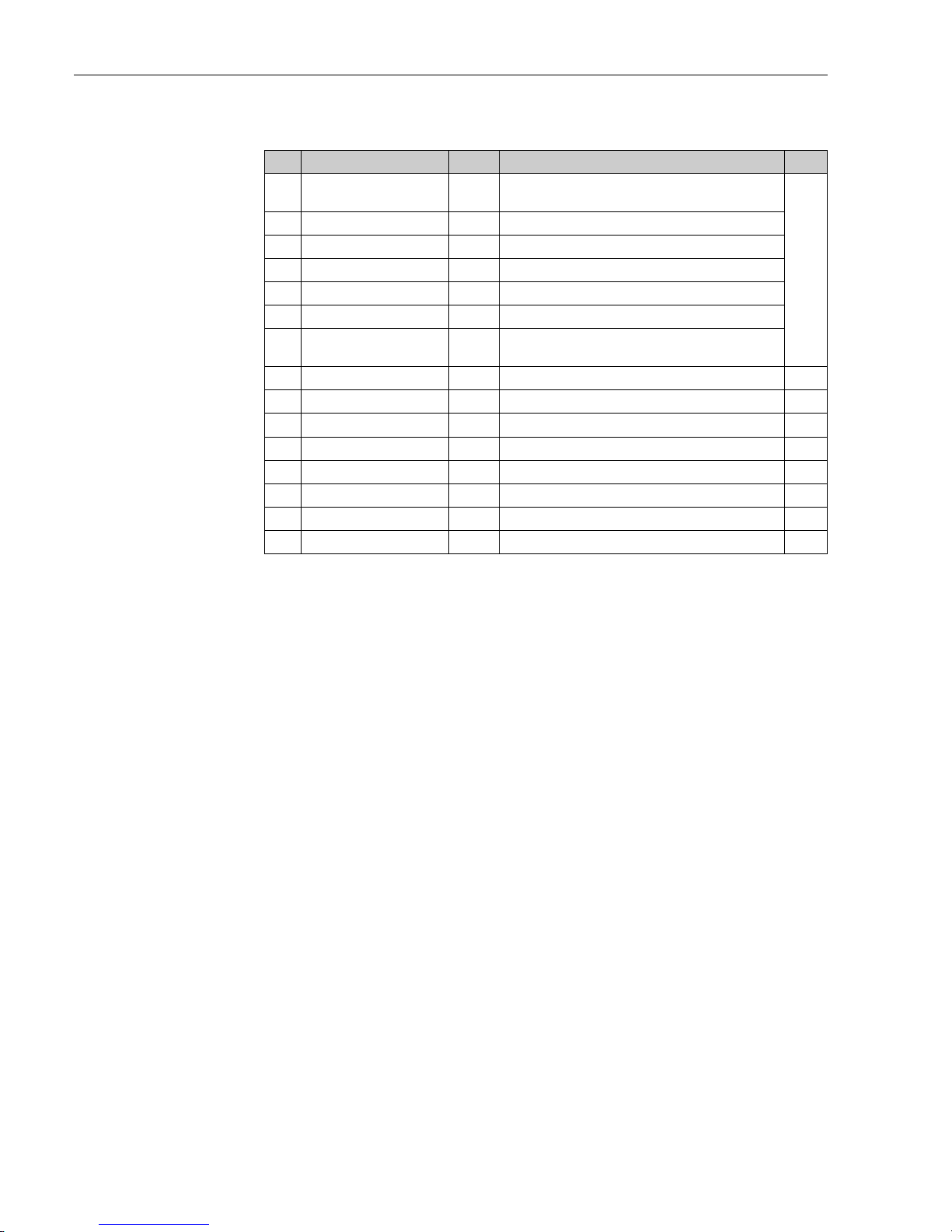
Order code (LT5-11AA025H1NC41A1000N0+PA)
Feat. Feature text Option Option text Qty.
020 Gauge head 1
0...0.1961bar/0.01961MPa/2.84psi,
Alu (ADC12), Low pressure
1
030 Gauge head connection 1A 10K 40A RF, Alu (AC4A), flange JIS B2220
040 Display; cover A Dial display; Acrylic
050 Crank unit 0 Not selected
060 Measuring range 2 5 m
070 Measuring tape 5 Measuring tape + PFA coated wire, seal pot/CRT
080 Float H
D400mm PVC wire connection 5.0kg,
density range >= 0.65...< 1.05, rings
090 Top anchor 1N 2x 10K 40A FF, PVC, flange JIS B2220 2
100 Guide wire C Diameter 4.6 mm strand wire, PFA coated 1
110 Bottom anchor; fixing bolt 4 SUS316; PVC 2
120 90 degree sheave elbow 1A1 1x 10K 40A RF, Alu (ADC6+AC4A), flange JIS B2220 1
130 135 degree sheave elbow 000 Not selected 0
140 Seal pot N 10K 40A FF, PVC, flange JIS B2220 1
150 Valve 0 Not selected 0
620 >>Accessory enclosed PA Gauge support, Iron 1
3 Installation
Page 31
Float level gauge LT5
Endress+Hauser 31
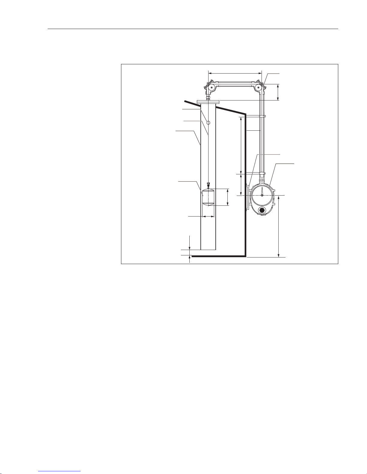
3.11.5 Compact cone roof tank for guide pipe
Figure 24: Compact cone roof tank for guide pipe
1. Vent hole
2. Measuring tape
3. Guide pipe (stilling well)
4. Float
5. 90° sheaves elbow
6. Gauge supporter
7. Gauge head
1
2
3
5
6
7
4
950 (37.4)
2000 - 3000
(78.74 - 118.11)
300
(11.81)
300
(11.81)
200
(7.87)
Ø140
(5.51)
1200 (47.24)
3 Installation
Page 32
Float level gauge LT5
32 Endress+Hauser
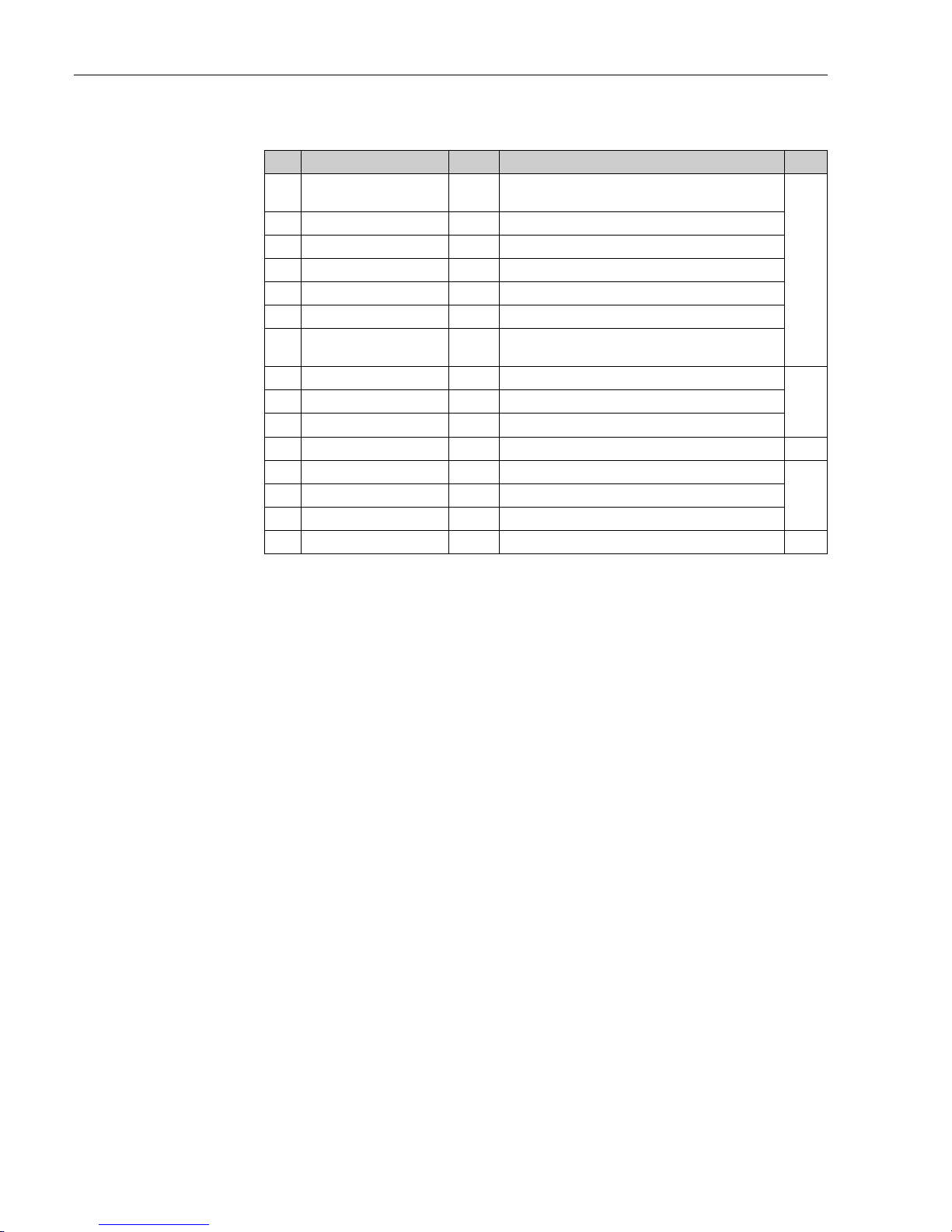
Order code (LT5-111A021L000011200000+PA)
Feat. Feature text Option Option text Qty.
020 Gauge head 1
0...0.1961bar/0.01961MPa/2.84psi,
Alu (ADC12), Low pressure
1
030 Gauge head connection 11 Rc 1-1/2, union nut, SUS316, thread JIS B0203
040 Display; cover A Dial display; Acrylic
050 Crank unit 0 Not selected
060 Measuring range 2 5 m
070 Measuring tape 1 Measuring tape, CRT
080 Float L
D140mm SUS316 tape connection 2.4kg,
density range >= 0.94...<= 2.0, no rings
090 Top anchor 00 Not selected
0100 Guide wire 0 Not selected
110 Bottom anchor; fixing bolt 0 Not selected
120 90 degree sheave elbow 112 2x Rp1-1/2, Alu (ADC6), thread JIS B0203 1
130 135 degree sheave elbow 000 Not selected
0140 Seal pot 0 Not selected
150 Valve 0 Not selected
620 >>Accessory enclosed PA Gauge support, Iron 1
3 Installation
Page 33
Float level gauge LT5
Endress+Hauser 33
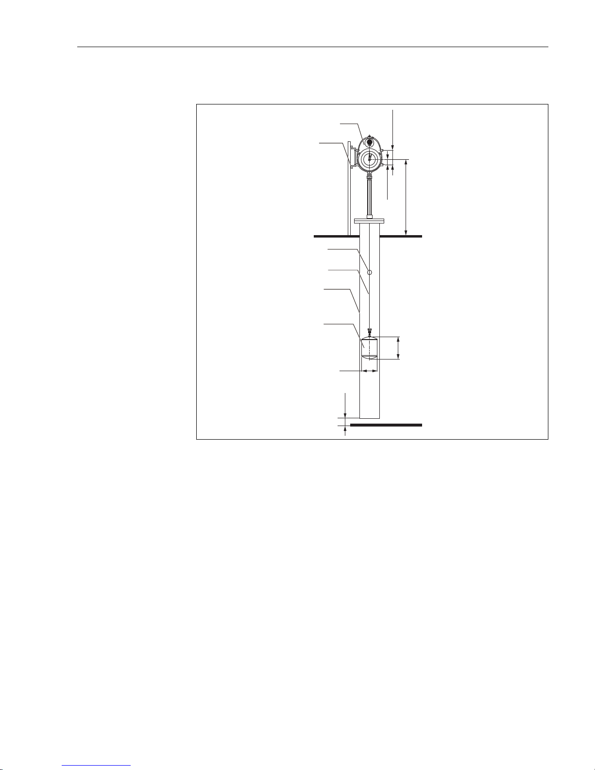
3.11.6 Mounting LT at tank top using guide pipe
Figure 25: Mounting LT at tank top
1. Gauge head
2. Gauge supporter
3. Vent hole
4. Measuring wire
5. Guide pipe (stilling well)
6. Float
60 (2.36)
170 (6.69)
1200 (47.24)
200
(7.87)
Ø140
(5.51)
100
(3.94)
1
2
3
5
6
4
3 Installation
Page 34
Float level gauge LT5
34 Endress+Hauser
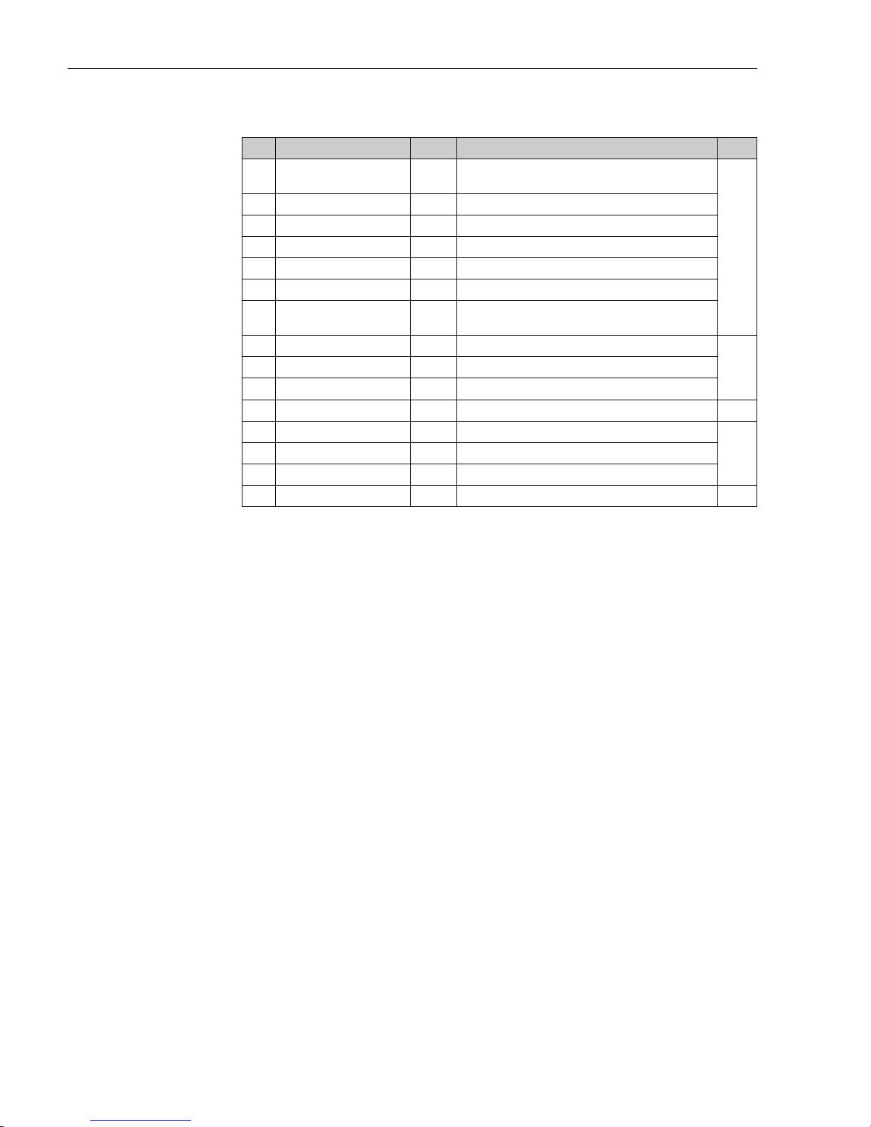
Order code (LT5-111C022L000000000000+PA)
Feat. Feature text Option Option text Qty.
020 Gauge head 1
0...0.1961bar/0.01961MPa/2.84psi,
Alu (ADC12), Low pressure
1
030 Gauge head connection 11 Rc 1-1/2, union nut, SUS316, thread JIS B0203
040 Display; cover C Dial display upside down; Acrylic
050 Crank unit 0 Not selected
060 Measuring range 2 5 m
070 Measuring tape 2 Measuring tape, tank top installation
080 Float L
D140mm SUS316 tape connection 2.4kg,
density range >= 0.94...<= 2.0, no rings
090 Top anchor 00 Not selected
0100 Guide wire 0 Not selected
110 Bottom anchor; fixing bolt 0 Not selected
120 90 degree sheave elbow 000 Not selected 1
130 135 degree sheave elbow 000 Not selected
0140 Seal pot 0 Not selected
150 Valve 0 Not selected
620 >>Accessory enclosed PA Gauge support, Iron 1
3 Installation
Page 35
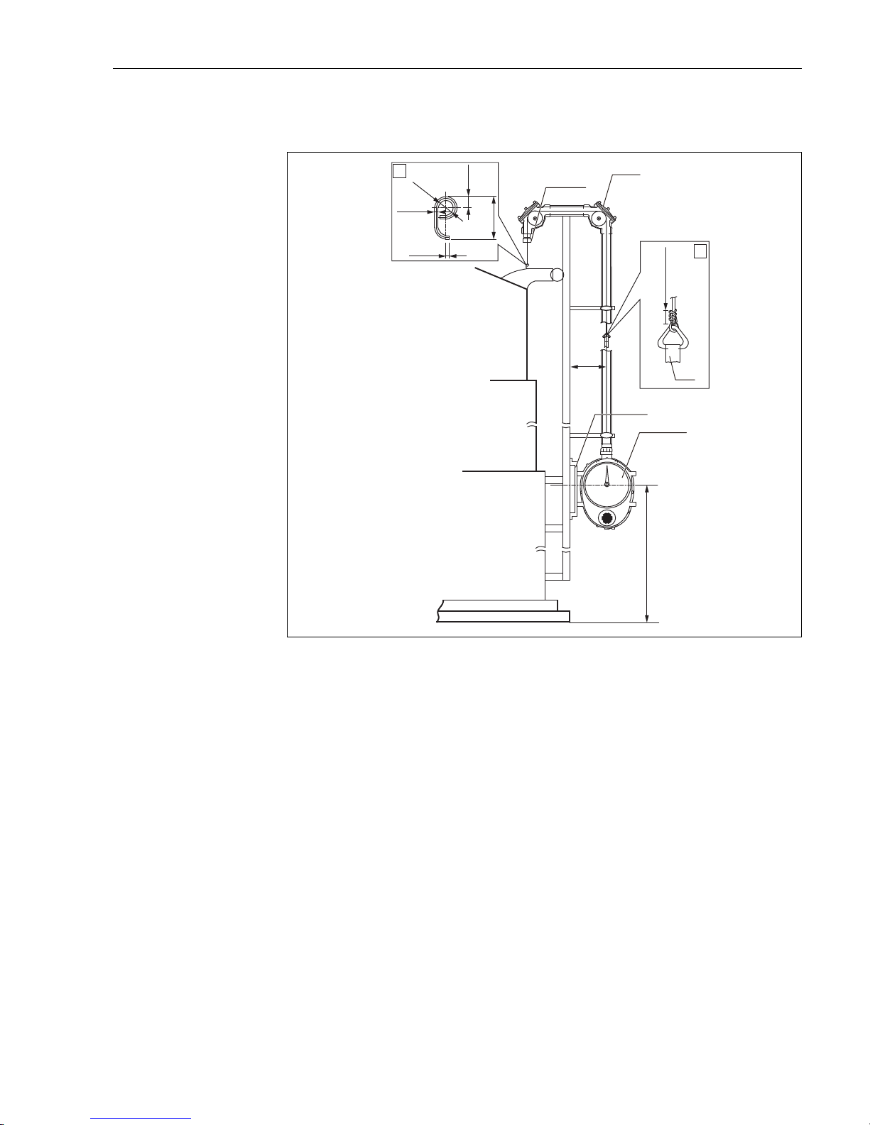
Float level gauge LT5
Endress+Hauser 35
3.11.7 Gas holder
Figure 26: Gas holder
A Gas holder wire hook
B Metal triangle fittings for measuring wire
1. Wire guide socket
2. 90° sheaves elbow
3. Measuring wire
4. Gauge supporter
5. Gauge head
A
3
B
30 - 40
(1.18 - 1.57)
Ø6
(0.24)
Ø20
(0.79)
52
(2.05)
16
(0.63)
5
(0.2)
1200 (47.24)
250
(9.84)
1
2
4
5
3 Installation
Page 36
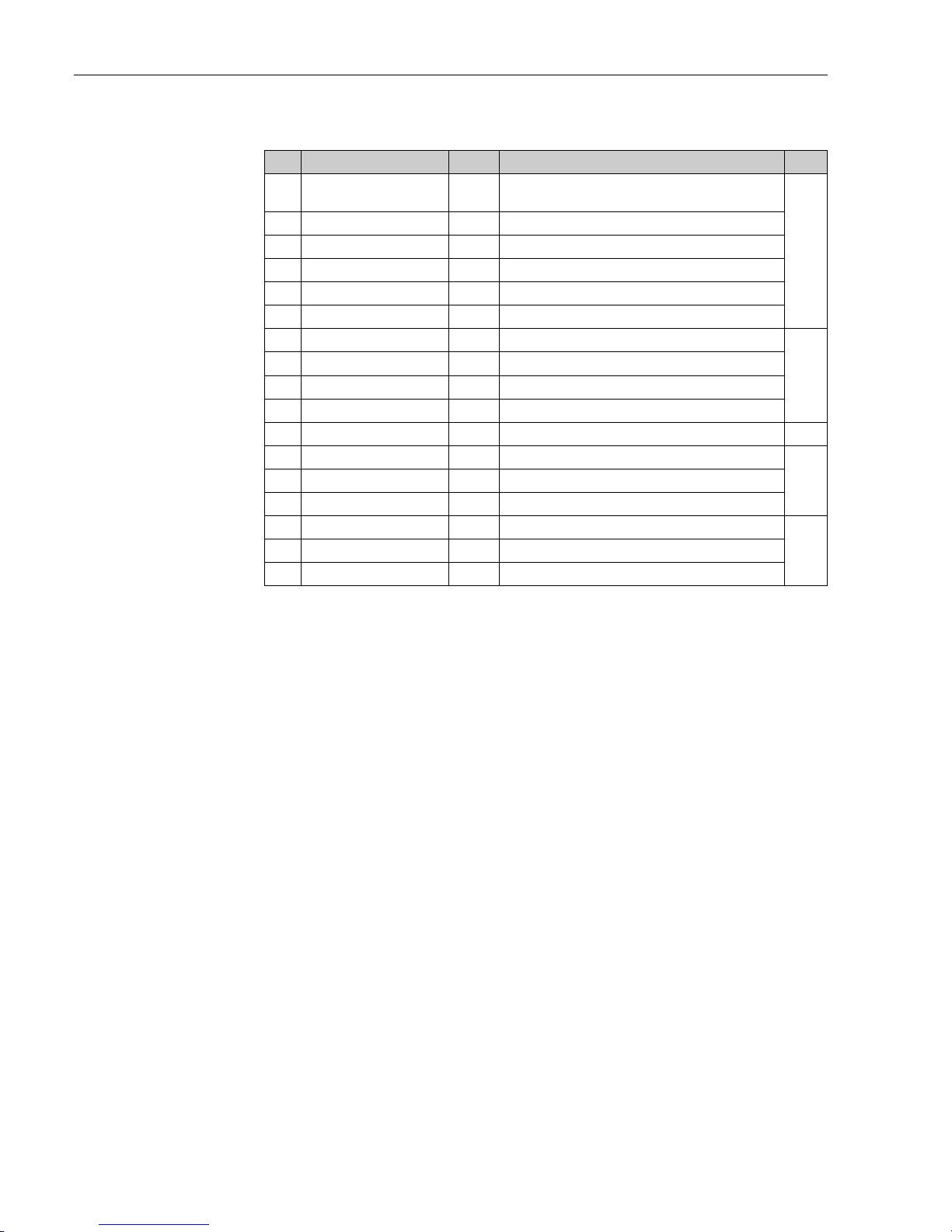
Float level gauge LT5
36 Endress+Hauser
Order code (LT5-111A0340000011200000+PAPFPH)
Feat. Feature text Option Option text Qty.
020 Gauge head 1
0...0.1961bar/0.01961MPa/2.84psi,
Alu (ADC12), Low pressure
1
030 Gauge head connection 11 Rc 1-1/2, union nut, SUS316, thread JIS B0203
040 Display; cover A Dial display; Acrylic
050 Crank unit 0 Not selected
060 Measuring range 3 10 m
070 Measuring tape 4 Measuring tape + wire, FRT
080 Float 0 Not selected
0
090 Top anchor 00 Not selected
100 Guide wire 0 Not selected
110 Bottom anchor; fixing bolt 0 Not selected
120 90 degree sheave elbow 112 2x Rp1-1/2, Alu (ADC6), thread JIS B0203 2
130 135 degree sheave elbow 000 Not selected
0140 Seal pot 0 Not selected
150 Valve 0 Not selected
620 >>Accessory enclosed PA Gauge support, Iron
1620 >>Accessory enclosed PF Wire guide socket, RC1-1/2
620 >>Accessory enclosed PH Gas holder wire hook
3 Installation
Page 37
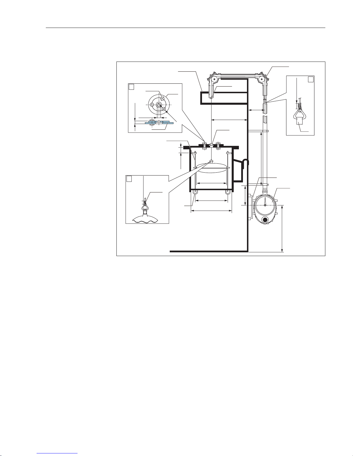
Float level gauge LT5
Endress+Hauser 37
3.11.8 Floating roof tank (FRT)
Figure 27: Floating roof tank
A Wire guide metal
B Upper part of float
C Metal triangle fittings for measuring wire
1. Roof stand
2. Wire guide socket
3. FRT wire guide metal
4. Guide bar: Ø
16 mm (0.63 in)
5. Stainless wire (provided)
6. Pipe end (1
B
Sch 40 to 80)
7. 90° sheaves elbow
8. Measuring wire
9. Gauge supporter
10. Gauge head
2000 - 3000
(78.74 - 118.11)
440
(17.32)
>520 (20.47)
Ø400
(15.74)
300
(11.81)
100
(3.94)
8 (0.31)
1200 (47.24)
250
(9.84)
A
B
<700 (27.56)
PCD.44
Ø70
(2.76)
Ø10
(0.39)
3-Ø11
8
C
30 - 40
(1.18 - 1.57)
30 - 40
(1.18 - 1.57)
1
2
3
4
6
7
9
10
5
3 Installation
Page 38
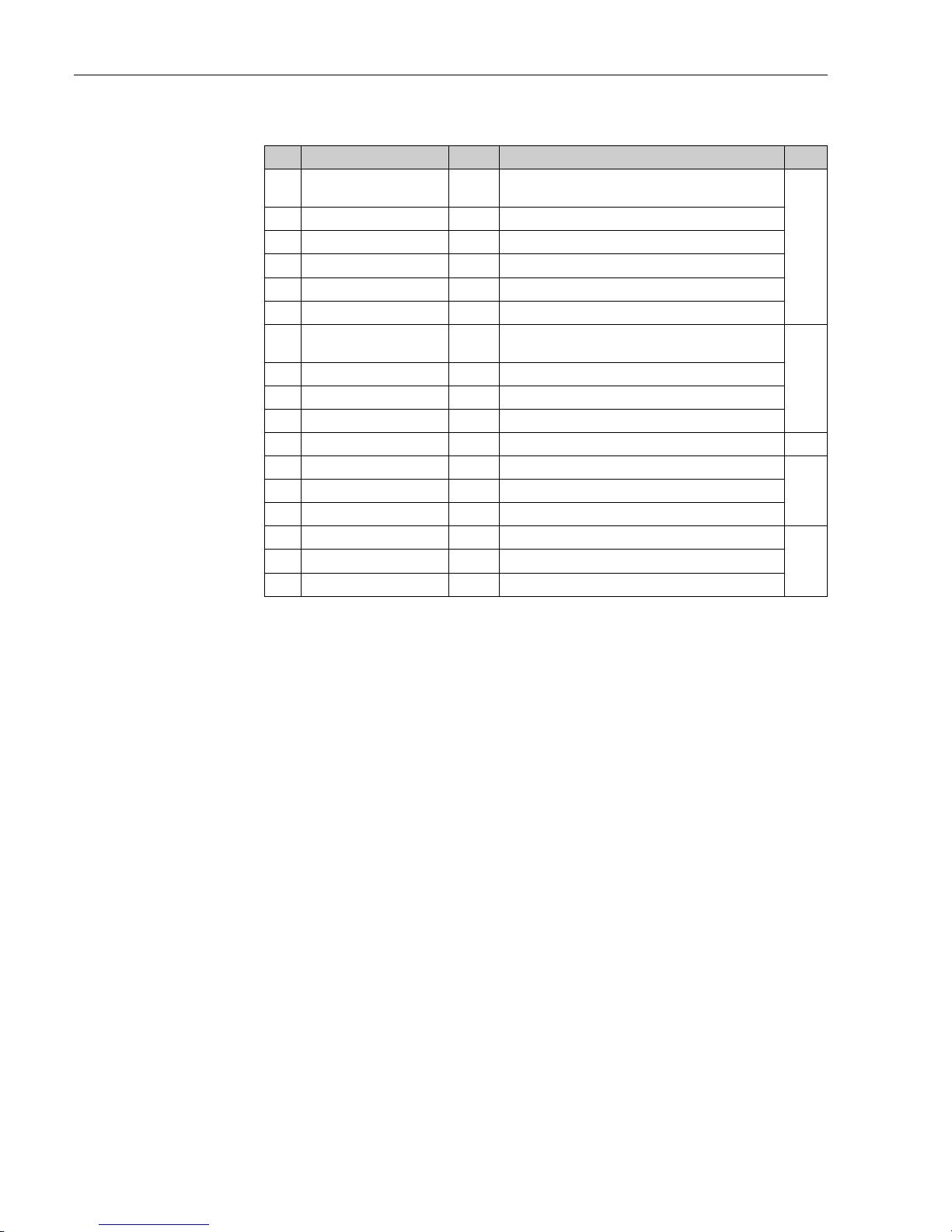
Float level gauge LT5
38 Endress+Hauser
Order code (LT5-111A054E000011200000+PAPEPF)
Feat. Feature text Option Option text Qty.
020 Gauge head 1
0...0.1961bar/0.01961MPa/2.84psi,
Alu (ADC12), Low pressure
1
030 Gauge head connection 11 Rc 1-1/2, union nut, SUS316, thread JIS B0203
040 Display; cover A Dial display; Acrylic
050 Crank unit 0 Not selected
060 Measuring range 5 20 m
070 Measuring tape 4 Measuring tape + wire, FRT
080 Float E
D400mm SUS316 wire connection 5.0kg,
density range >= 0.65...< 1.05, rings
0
090 Top anchor 00 Not selected
100 Guide wire 0 Not selected
110 Bottom anchor; fixing bolt 0 Not selected
120 90 degree sheave elbow 112 2x Rp1-1/2, Alu (ADC6), thread JIS B0203 2
130 135 degree sheave elbow 000 Not selected
0140 Seal pot 0 Not selected
150 Valve 0 Not selected
620 >>Accessory enclosed PA Gauge support, Iron
1620 >>Accessory enclosed PE Wire guide metal FRT
620 >>Accessory enclosed PF Wire guide socket, RC1-1/2
3 Installation
Page 39
Float level gauge LT5
Endress+Hauser 39
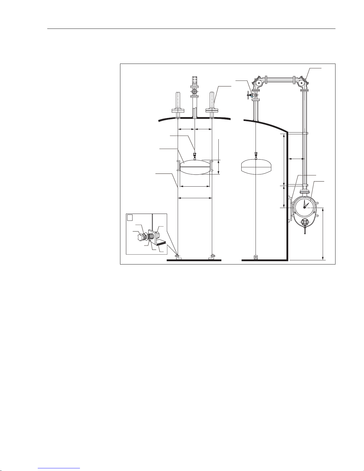
3.11.9 Doom roof tank for medium pressure
Figure 28: Dome roof tank for medium pressure
A Anchor hook
1. Top anchor
2. Measuring tape
3. float
4. Guide wire
5. Nut
6. Wetting part (wetting to the tank)
7. Anchor hook
8. Guide wire
9. Bolt
10. Washer
11. Plug gate valve
12. 90° sheaves elbow
13. Gauge supporter
14. Gauge head
220
(8.66)
250
(9.84)
2000 - 3000
(78.74 - 118.11)
300
(11.81)
200(7.87)
440
(17.32)
Ø400
(15.74)
1200
(47.24)
220
(8.66)
2
3
4
1
A
5
6
7
8
9
10
12
13
14
11
3 Installation
Page 40
Float level gauge LT5
40 Endress+Hauser
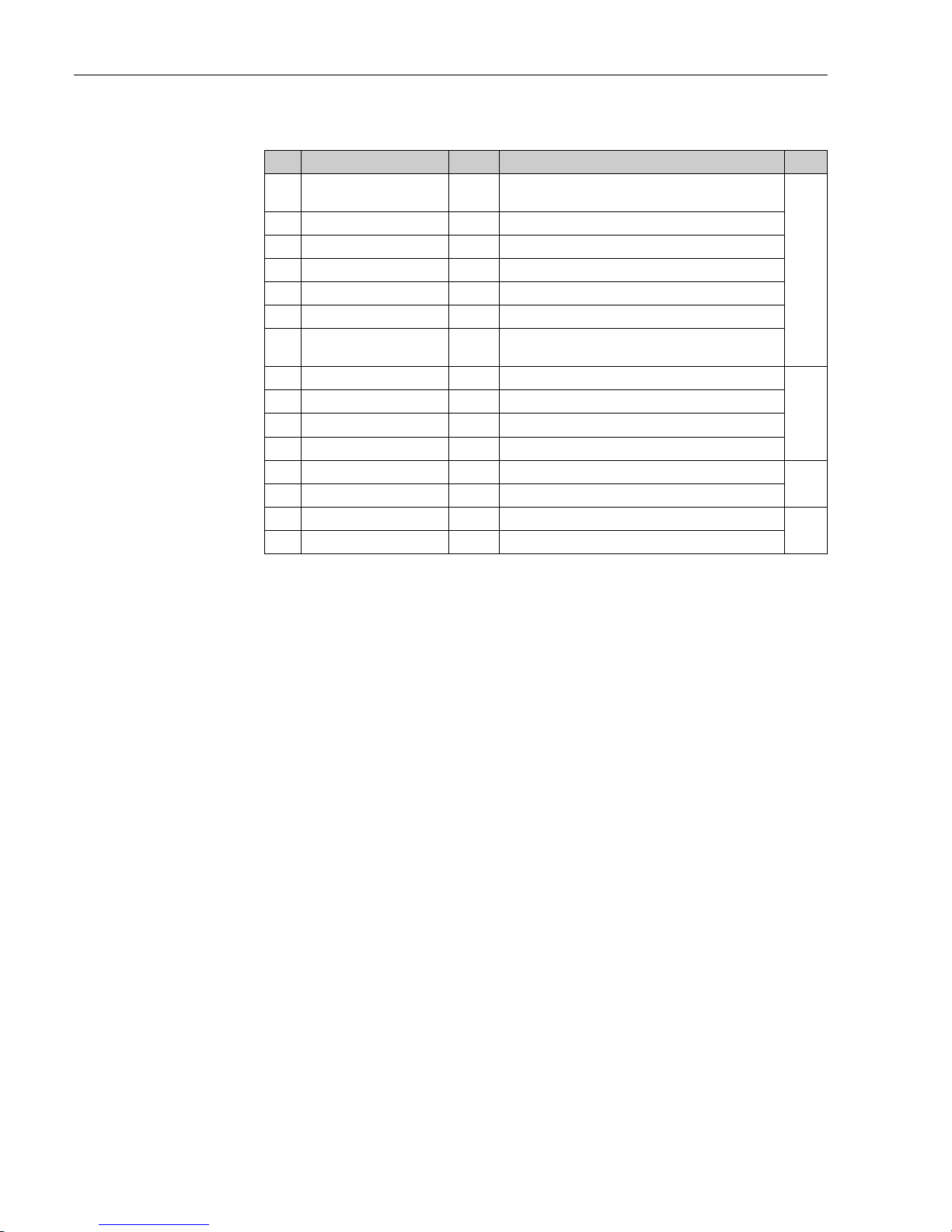
Order code (LT5-44AB151R4AA24A200001+PA)
Feat. Feature text Option Option text Qty.
020 Gauge head 4
0...0.9807bar/0.09807MPa/14.22psi,
Alu (AC4CT6), medium pressure
1
030 Gauge head connection 4A 10K 40A RF, alu (AC4CT6), flange JIS B2220
040 Display; cover B Dial display; Glass + Iron
050 Crank unit 1 Selected
060 Measuring range 5 20 m
070 Measuring tape 1 Measuring tape, CRT
080 Float R
D400mm SUS316 tape connection 8.3kg,
density range >= 0.5...<= 0.7, rings
090 Top anchor 4A 2x 10K 40A RF, Alu (AC4CT6), flange JIS B2220
2
100 Guide wire A Diameter 3mm solid wire
110 Bottom anchor; fixing bolt 2 SUS316; SUS316
120 90 degree sheave elbow 4A4 2x 10K 40A RF, Alu (AC4CT6), flange JIS B2220
130 135 degree sheave elbow 000 Not selected
0
140 Seal pot 0 Not selected
150 Valve 1 10K 40A RF, SCS13, flange JIS B2220
1
620 >>Accessory enclosed PA Gauge support, Iron
3 Installation
Page 41
Float level gauge LT5
Endress+Hauser 41
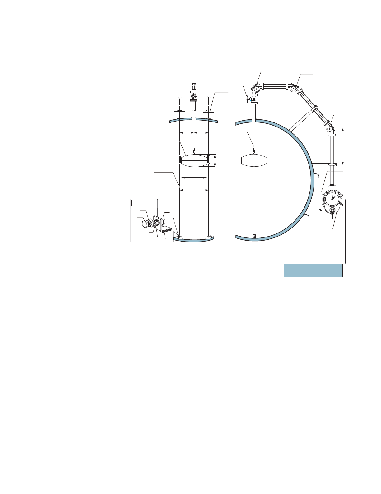
3.11.10 Spherical tank for high pressure
Figure 29: Spherical tank for high pressure
A Anchor hook
1. Top anchor
2. float
3. Guide wire
4. Measuring tape
5. Nut
6. Wetting part (wetting to the tank)
7. Anchor hook
8. Guide wire
9. Bolt
10. Washer
11. Plug gate valve
12. 90° sheaves elbow
13. 135° sheaves elbow
14. Gauge supporter
15. Gauge head
A
5
6
7
8
9
10
220
(8.66)
1000 (39.4)
200(7.87)
440
(17.32)
Ø400
(15.74)
1200 (47.24)
220
(8.66)
2
3
4
1
12
13
13
14
11
15
3 Installation
Page 42
Float level gauge LT5
42 Endress+Hauser
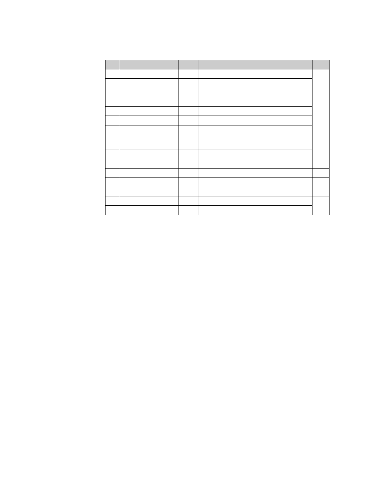
Order code (LT5-66GB153R6GA26G16G204+PC)
Feat. Feature text Option Option text Qty.
020 Gauge head 6 0...24.5bar/2.45MPa/355.25psi, Iron, high pressure
1
030 Gauge head connection 6G 20K 40A RF, Iron, flange JIS B2220
040 Display; cover B Dial display; Glass + Iron
050 Crank unit 1 Selected
060 Measuring range 5 20 m
070 Measuring tape 3 Measuring tape, seal pot/BT
080 Float R
D400mm SUS316 tape connection 8.3kg,
density range >= 0.5...<= 0.7, rings
090 Top anchor 6G 2x 20K 40A RF, Iron, flange JIS B2220
2100 Guide wire A Diameter 3mm solid wire
110 Bottom anchor; fixing bolt 2 SUS316; SUS316
120 90 degree sheave elbow 6G1 1x 20K 40A RF, Iron, flange JIS B2220 1
130 135 degree sheave elbow 6G2 2x 20K 40A RF, Iron, flange JIS B2220 2
140 Seal pot 0 Not selected 0
150 Valve 4 20K 40A RF, SCS13, flange JIS B2220
1
620 >>Accessory enclosed PC Gauge supporter, Iron, high pressure
3 Installation
Page 43
Float level gauge LT5
Endress+Hauser 43
3.12 Guide wire installation
Installation procedure
• Be careful not to bend the guide wire.
• Two guide wires should be arranged in parallel to one other and perpendicular to the tank floor.
• Check two packings (for top anchor and tank flange) on which slip washers are used, before setting
the guide wires.
• Repairing the guide wires and anchor hooks, once the tank is full, can be very difficult. Be sure to
inspect their hardness before filling.
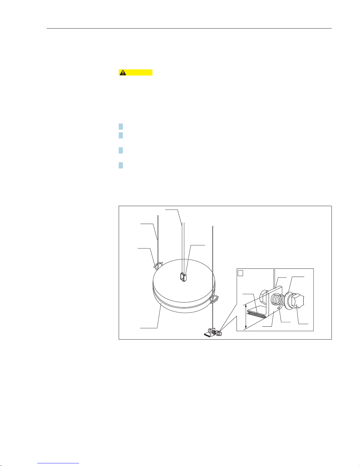
1. Open the cover of the top anchor located in the top of the tank.
2. Straighten the guide wire, and lower it from the center hole in the top anchor, then temporarily
attach the end of the wire to the top anchor.
3. Insert the guide wire into the guide ring on the float at the bottom of the tank then, secure the
guide wire to the anchor hooks by using two bolts and nuts.
4. Cut and bend the end of the guide wire to prevent it from getting caught in the float.
• Place the guide wire against the surface of inside anchor hook B and insert it through the
anchor hook hole. Wind the end of the guide wire so that the excess is within dimension A.
• Wind the wires 1 to 2 times each, on both the B and C sides. Adjust the number of times wound
as needed.
Figure 30: Guide wire installation 1
A Anchor hook
1. Guide wire
2. Guide ring
3. Float
4. Measuring tape
5. Universal joint
6. Wetting part
7. Washer
8. Anchor hook
9. Bolt
CAUTION
A
5
6
3
4
2
1
a
7
8
1
9
b
3 Installation
Page 44
Float level gauge LT5
44 Endress+Hauser
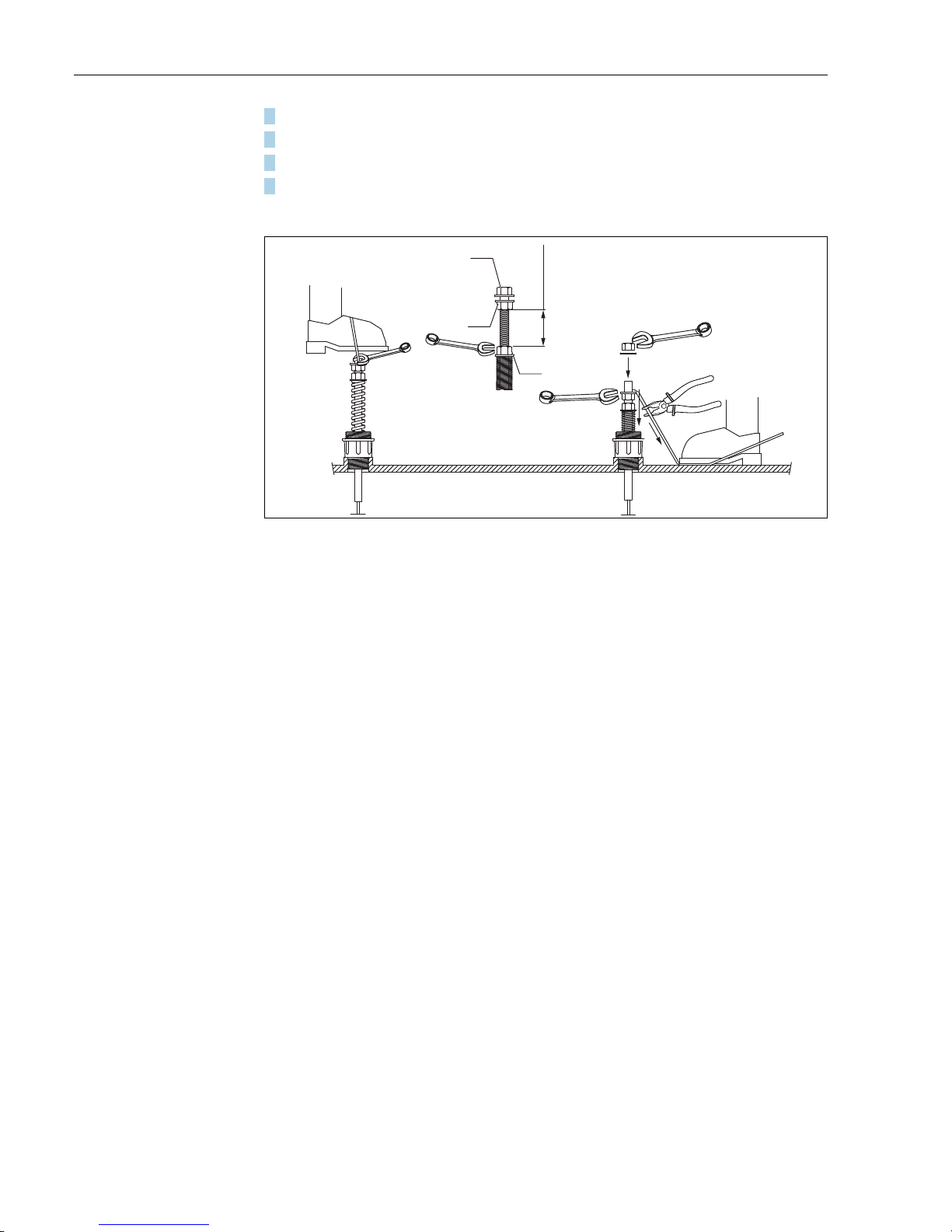
5. Extend guide wire to the top of the tank and secure it to the top anchor.
6. Bend end of the guide wire against the main shaft and cut it off leaving approx.100mm.
7. Tighten the end nuts [1] and [2].
8. Secure the wire with the nut [3] and release the spring.
This completes the installation procedure.
Figure 31: Guide wire installation 2
1. Nut 1
2. Nut 2
3. Nut 3
20 - 30
(0.79 - 1.81)
1
2
3
3 Installation
Page 45
Float level gauge LT5
Endress+Hauser 45
3.13 Measuring tape and wire installation
• Do not bend or damage the measuring tape.
• Be sure to keep the measuring tape from twisting inside of the tank or pipe.
• There are small holes at intervals of 20 mm (for feet: 1 inch) along half of the entire length of mea-
suring tape. Attach the measuring tape to LT so that the side with the holes are wound by LT.
• Check to make sure the measuring tape does not come off the sheave elbow roller. Inspect the measuring tape after installation.
• Secure the safety of workers to counteract the exteme dangers of poor footing when measuring wire
is required to be inserted into 135° sheave elbows.
• Repairing the connection components between the float and measuring wires, once the tank is fill,
can be very difficult. Be sure to inspect them thoroughly before filling.
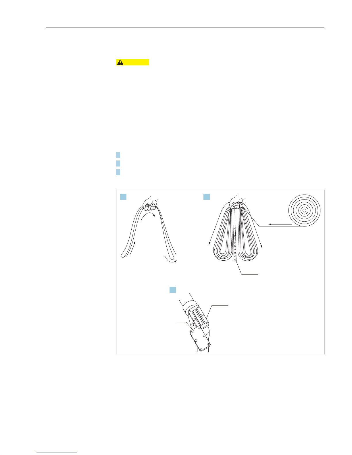
Preparation procedure
1. Extend the measuring wire and fold, as shown below to a length of 1.5m so as not to twist it.
2. Open the rear cover of LT and sheave elbow cover.
3. Attach the measuring wire without twisting.
This completes the measuring tape installation.
Figure 32: Measuring tape preparation
1. Small holes
2. Sheave elbow
3. Cover
CAUTION
1. 1.
2.
1
2
3
15000 (59.1)
3 Installation
Page 46
Float level gauge LT5
46 Endress+Hauser
3.13.1 Measuring tape installation at cone roof tank
Installation procedure
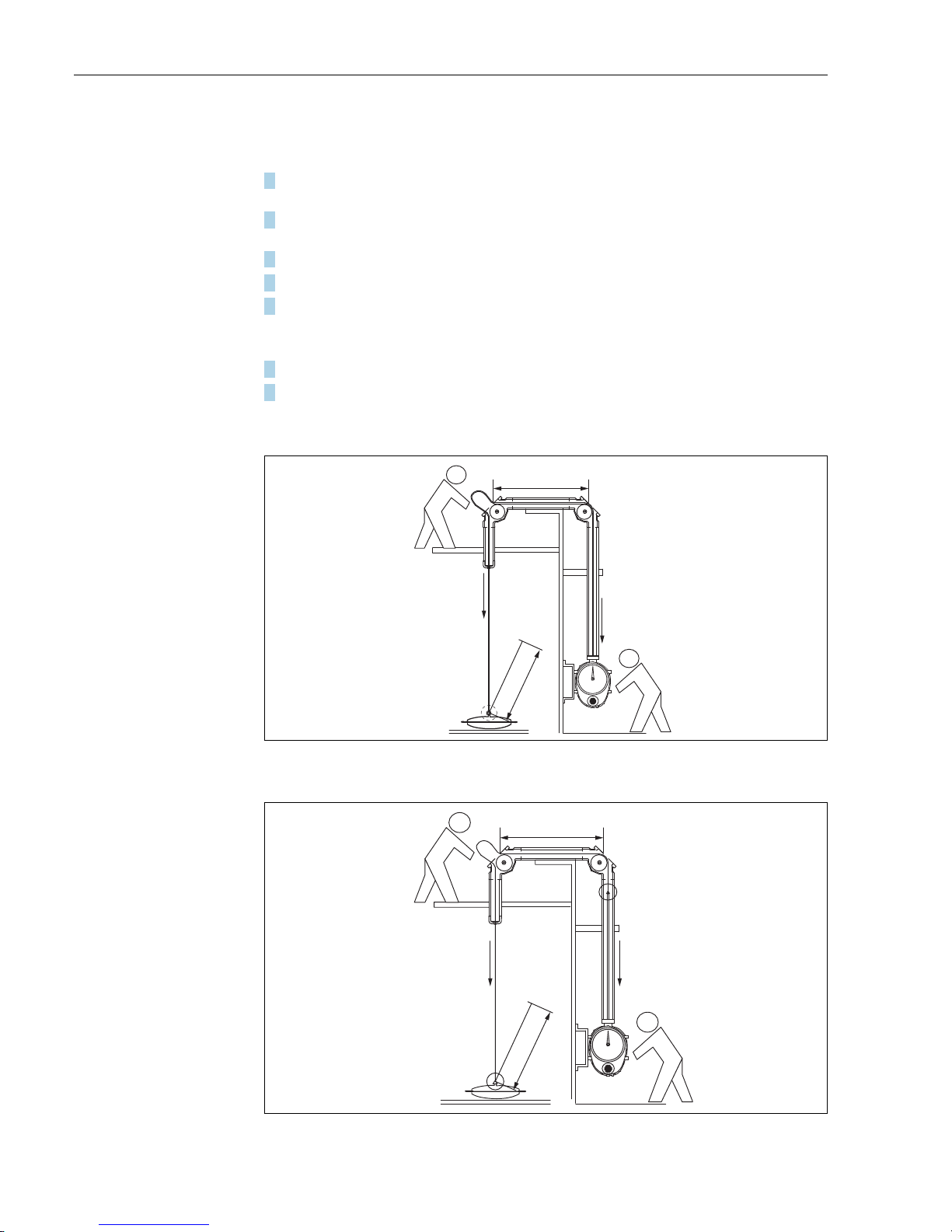
1. Insert the non-perforated side of the measuring tape directly into the tank from the 90° sheave
elbow.
2. Insert the other end of the measuring tape (perforated and looped) through the 90° sheave elbow
to LT located directly above the tank.
3. Secure end of the measuring tape to tape drum, wind tape twice around drum and pull into tank.
4. Cut the measuring tape off leaving approx. 1.5m
5. Connect the measuring tape to the float.
• Refer to "3.11.2 Connection Procedure of Measuring Tape to Float" for details on the connection
of the measuring tape.
6. Confirm that measuring tape is not twisted.
7. Replace the sheave elbow cover.
This completes the measuring tape installation at cone roof tank.
When installing measuring tape
Figure 33: Measuring installation
a Guide pipe
When installing measuring tape and measuring wire
Figure 34: Measuring tape wire installation
a Guide pipe
1500(59.1)
a
1500(59.1)
a
3 Installation
Page 47
Float level gauge LT5
Endress+Hauser 47
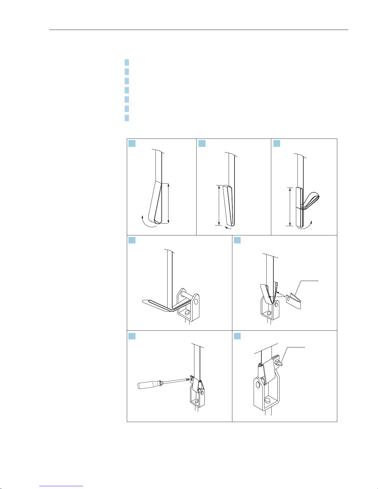
3.13.2 Connection procedure of measuring tape to float
1. Bend the measuring tape at the length of 65mm.
2. Bend the measuring tape once again at the location shown above.
3. Bend the measuring tape twice at the center.
4. Insert the joint shaft into the bended measuring tape.
5. Insert the tape clamp into the loop of the tape.
6. Tighten the clamp strip with a bolt and nut.
7. Strip the protruding end of the bolt with pliers to lock the nut.
This completes the connection procedure of measuring tape to float.
Figure 35: Connection of measuring tape to float
1. Tape clamp
2. Screw thread
1.
4.
6. 7.
5.
2. 3.
65 (2.56)
65 (2.56)
65 (2.56)
1
2
3 Installation
Page 48
Float level gauge LT5
48 Endress+Hauser
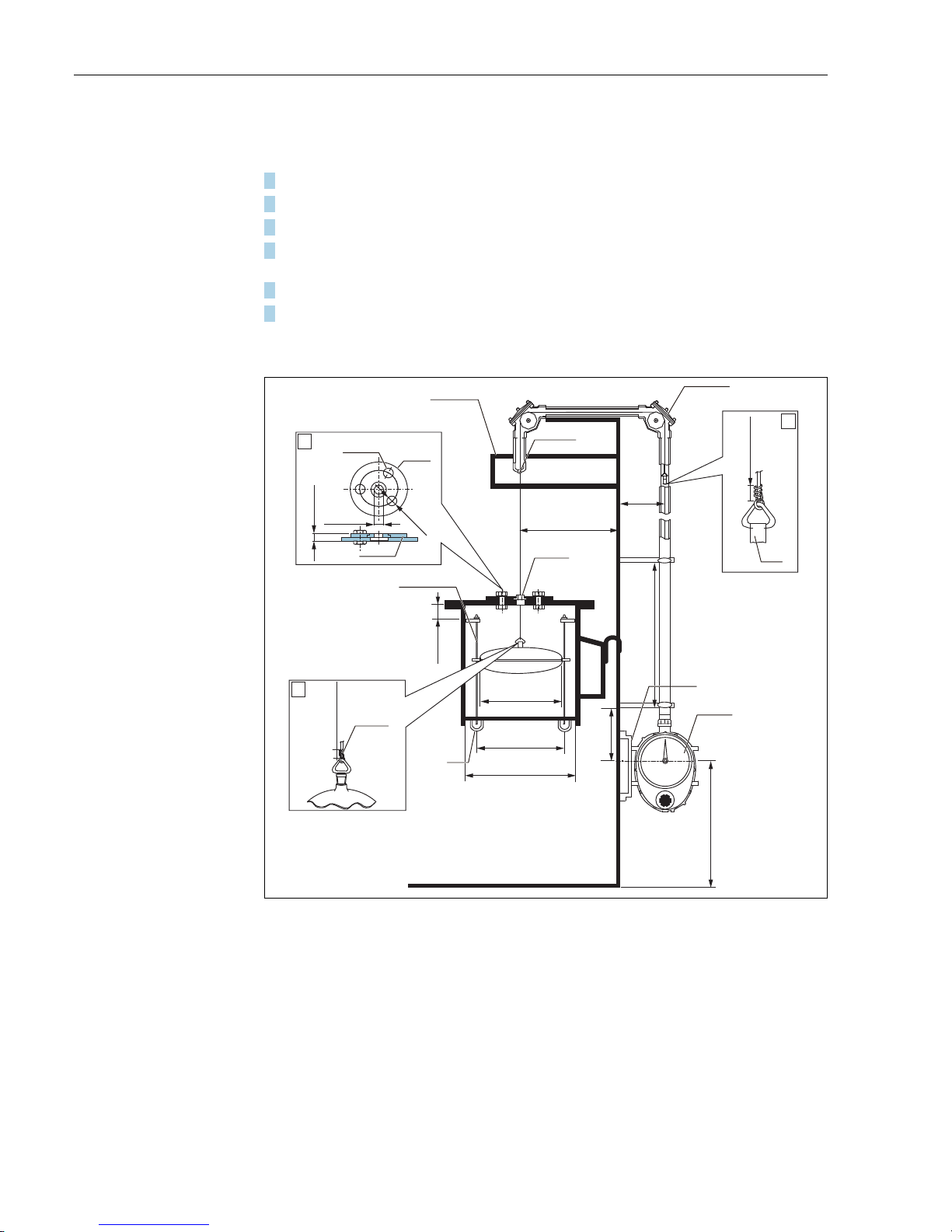
3.13.3 Measuring tape installation at floating roof tank
Installation procedure
1. Insert the end of the measuring wire into the tank through the 90° sheave elbow.
2. Attach the other end of the measuring tape to the tank.
3. Connect the measuring wire to the float.
4. Connect the measuring wire to the measuring tape on the top of the tank and feed the measuring
tape to LT.
5. Confirm that measuring tape is not twisted.
6. Replace the sheave elbow cover.
This completes the measuring tape installation at floating roof tank.
Figure 36: Measuring Wire
A Wire guide metal
B Upper part of float
C Hook for measuring wire
1. Roof stand
2. Wire guide socket
3. FRT wire guide metal
4. Guide bar: Ø
16 mm (0.63 in)
5. Stainless wire (provided)
6. Pipe end (1
B
Sch 40 to 80)
7. 90° sheaves elbow
8. Measuring wire
9. Gauge supporter
10. Gauge head
2000 - 3000
(78.74 - 118.11)
440
(17.32)
>520 (20.47)
Ø400
(15.74)
300
(11.81)
100
(3.94)
8 (0.31)
1200 (47.24)
250
(9.84)
A
B
<700 (27.56)
PCD.44
Ø70
(2.76)
Ø10
(0.39)
3-Ø11
8
C
30 - 40
(1.18 - 1.57)
30 - 40
(1.18 - 1.57)
1
2
3
4
6
7
9
10
5
3 Installation
Page 49
Float level gauge LT5
Endress+Hauser 49
3.13.4 Installation of measuring tape at medium/high pressure
tank
• Do not bend or damage the measuring tape.
• Be sure to keep the measuring tape from twisting inside of the tank or pipe.
• There are small holes at intervals of 20 mm (for feet: 1 inch) along half of the entire length of mea-
suring tape. Attach the measuring tape to LT so that the side with the holes are wound by LT.
• Check to make sure the measuring tape does not come off the sheave elbow roller. Inspect the mea-
suring tape after installation.
• Secure the safety of workers to counteract the exteme dangers of poor footing when measuring wire
is required to be inserted into 135° sheave elbows.
• Repairing the connection components between the float and measuring wires, once the tank is fill,
can be very difficult. Be sure to inspect them thoroughly before filling.
Installation procedure
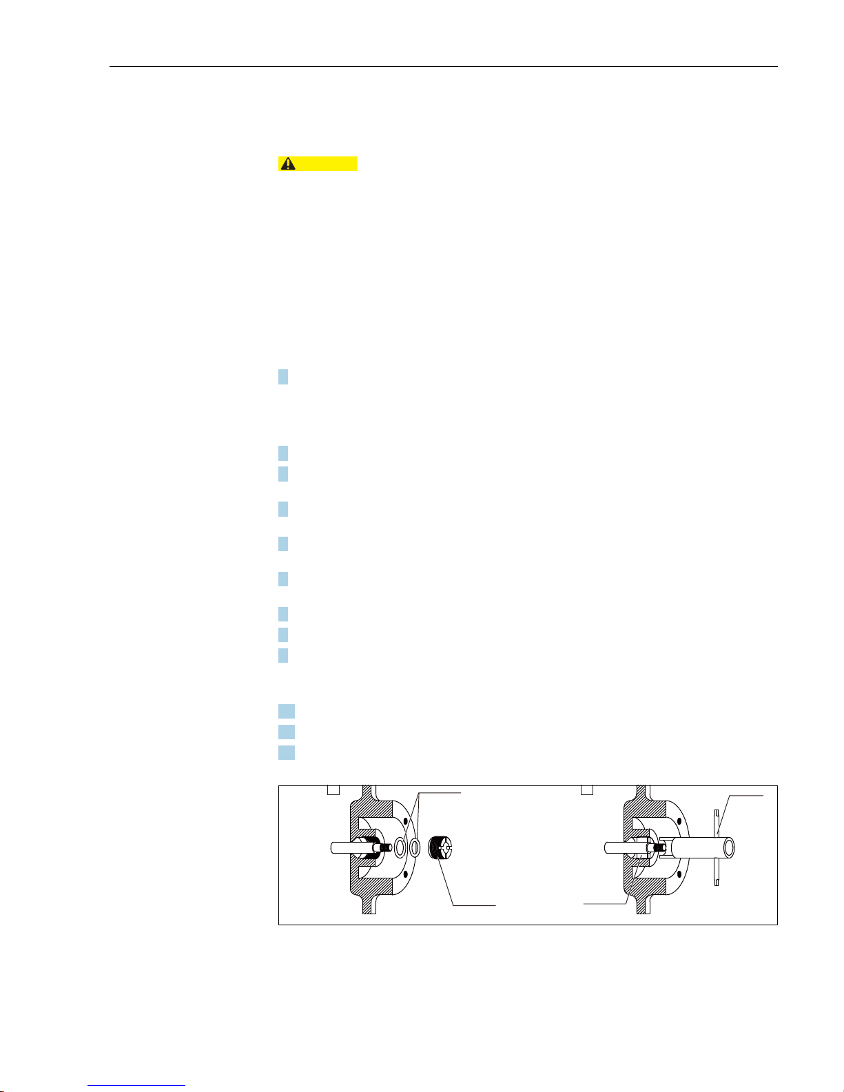
1. Rotate gate valve counter clockwise and open gate valve completely, and then remove sheave
elbow cover and rear cover of LT.
• Remove gland of the gauge head rear cover with a gland fixing tool.
• Remove O-rings (2pcs.).
2. Remove tape guide, and lock screw.
3. Insert non-perforated end of the measuring tape into tank through 90° sheave elbow (refer to
Figure 33).
4. Insert the perforated and looped end of the measuring tape thorough 135° sheave elbows to LT
(refer to Figure 34).
5. Once the measuring tape is inserted into measuring gauge through narrow opening in dust cover,
secure to the tape drum with set screw, then wind the tape twice around tape drum.
6. Loosen screws (2pcs.) and adjust measuring tape so that it does not obstruct opening in dust
cover.
7. Pull measuring tape inside the tank.
8. Cut measuring tape off leaving approx. 1.5m.
9. Connect measuring tape to the float.
• Refer to "3.11.2 Connection Procedure of Measuring Tape to Float" for details on the connection
of the measuring tape.
10. Confirm that measuring tape is not twisted.
11. Replace sheave elbow cover.
12. Follow Figure 33 and tighten gland.
This completes the installation procedure.
Figure 37: Gland Fixing Tool
A Wire guide metal
B Upper part of float
C Hook for measuring wire
1. Roof stand
2. Wire guide socket
3. FRT wire guide metal
CAUTION
A
B
1
2
2
3
3 Installation
Page 50
Float level gauge LT5
50 Endress+Hauser
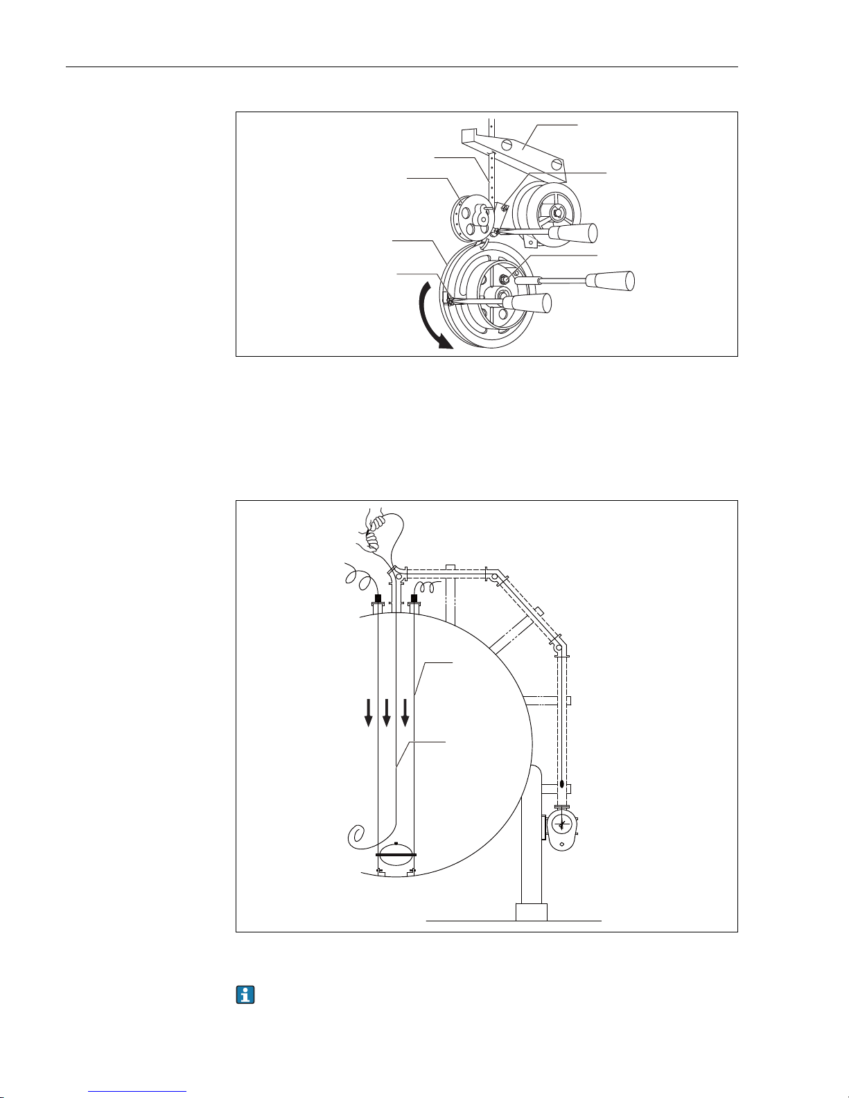
Figure 38: LT parts configuration
1. Measuring tape
2. Sprocket
3. Tape drum
4. Set screw for tape
5. Lock screw
6. Tape guide
7. Dust cover
Figure 39: Measuring tape installation
1. Guide wire
2. Measuring tape
Cut the measuring tape off leaving approximately 1500 mm (59.1 in) from the connection of the
float after connecting measuring tape to the tank.
1
2
3
4
5
6
7
1
2
3 Installation
Page 51
Float level gauge LT5
Endress+Hauser 51
3.13.5 Internal parts adjustment
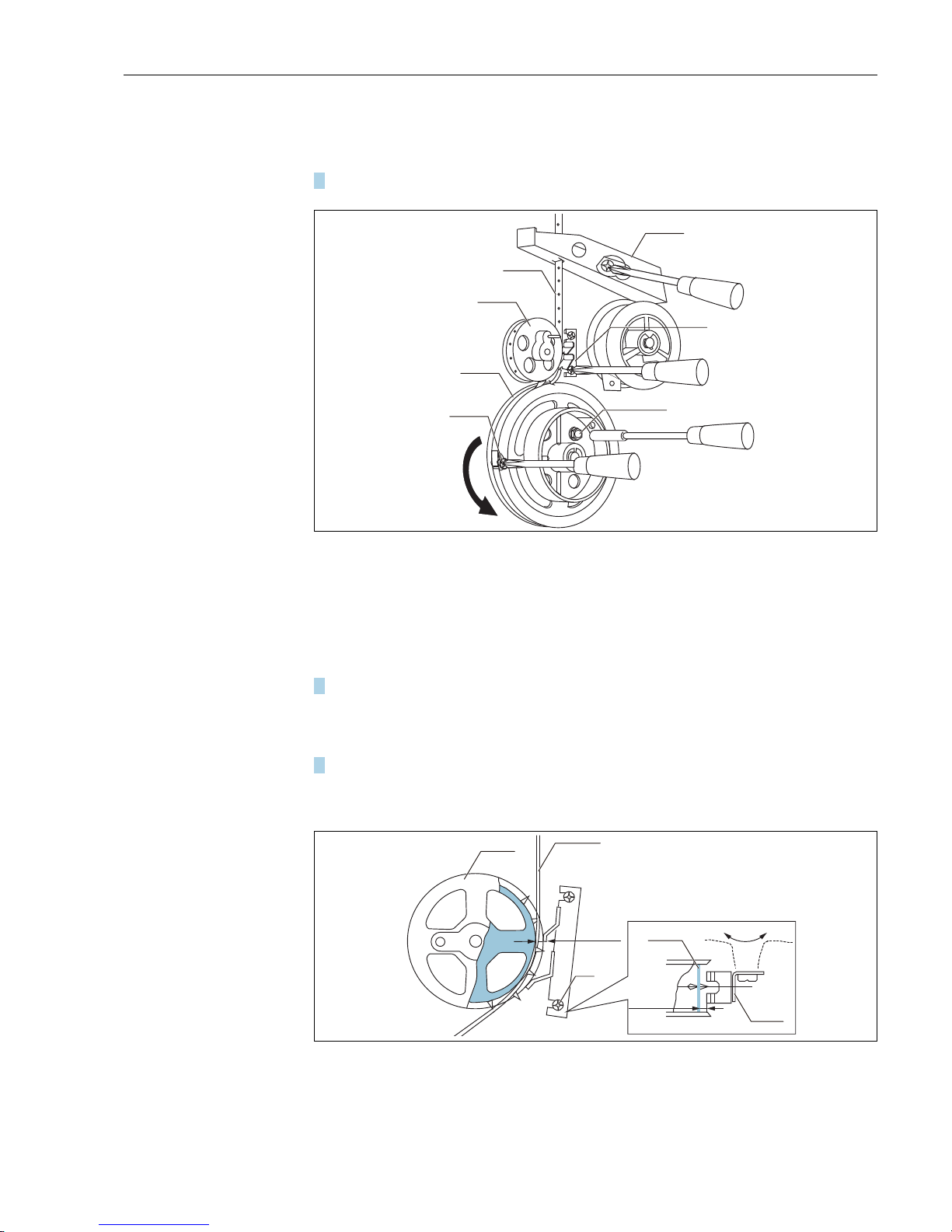
Tape guide adjustment procedure
1. Turn the LT tape drum in the direction indicated by arrow to put tension on the measuring tape.
Figure 40: Tape drum
1. Measuring tape
2. Sprocket
3. Tape drum
4. Set screw for tape
5. Dust cover
6. Tape guide
7. Lock screw
2. After the measuring tape is properly set, adjust the two tape guide heads so that they are positioned at 2mm from the tape surface.
• The measuring tape may come off the sprocket pins [6] since it moves abruptly with liquid
waves. The tape guide prevents this.
3. When the dust cover is installed, loosen screws (2pcs.) and adjust measuring tape [7] so that it
does not obstruct opening in dust cover.
This completed the tape guide adjustment procedure.
Figure 41: Tape guide adjustment
1. Sprocket
2. Measuring tape
3. Set screw
4. Measuring tape
5. Tape guide
1
2
3
4
5
6
7
2
1
3
2 (0.08)
4
2 (0.08)
5
3 Installation
Page 52
Float level gauge LT5
52 Endress+Hauser
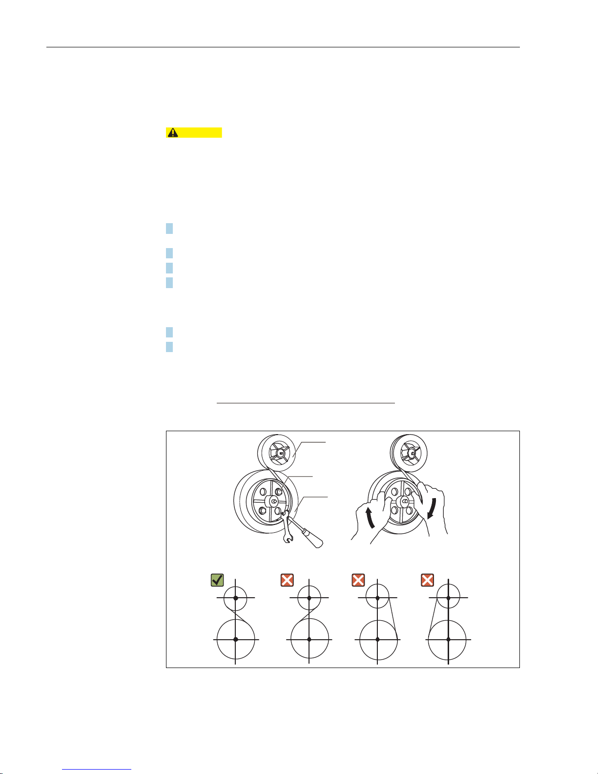
3.13.6 Setting conster drum
Setting procedure
The conster drum should be set after the measuring tape has been installed.
• When winding the conster motor from the large drum to the small drum, keep a firm grip on the
large drum until the spring is completely wound. Releasing it may result in injury due to the spring
recoiling.
• The conster may separate from the track of the large conster drum, or disproportionate torque may
result when the excessive force is applied, resulting in inaccurate readings. Handle with care.
• When winding the conster from the small conster drum to the large conster drum, keep firm grip
on the large drum until the measuring tape is taut.
1. After confirming that the lock screw has been removed, secure the head of the conster to the large
conster drum with the bolts and nuts.
2. Rotate the conster drum in the direction indicated by the figure below.
3. When fixing the conster drum, rotate the tape drum counter clockwise to tighten the tape.
4. When the tank is empty, roll the tape twice around a small conster drum and secure it with bolts.
• Once the tank is fill, measure the surface level of the fluid and use the equation on the following
page to determine the number of times the tape should be rolled. Roll the tape around a large
conster drum the exact number of times required based on the calculation.
5. Replace rear cover.
6. Close the gland of LT5-4 or LT5-6 rear cover.
This completes the setting procedure.
Figure 42: Conster drum setting
1. Conster drum (small)
2. Lock screw
3. Conster drum (Large)
CAUTION
ᕳྲྀᅇᩘ㻌㻩
䝍䞁䜽㧗䛥 䠄 ᐃ䝇䝟䞁䠅㻌㻙㻌ᐇ㝿䛾ᾮ 䠄ᐇᑻ್䠅
㻢㻜㻜 䠄༢ 䠖 㼙㼙㻕
1
2
3
3 Installation
Page 53
Float level gauge LT5
Endress+Hauser 53
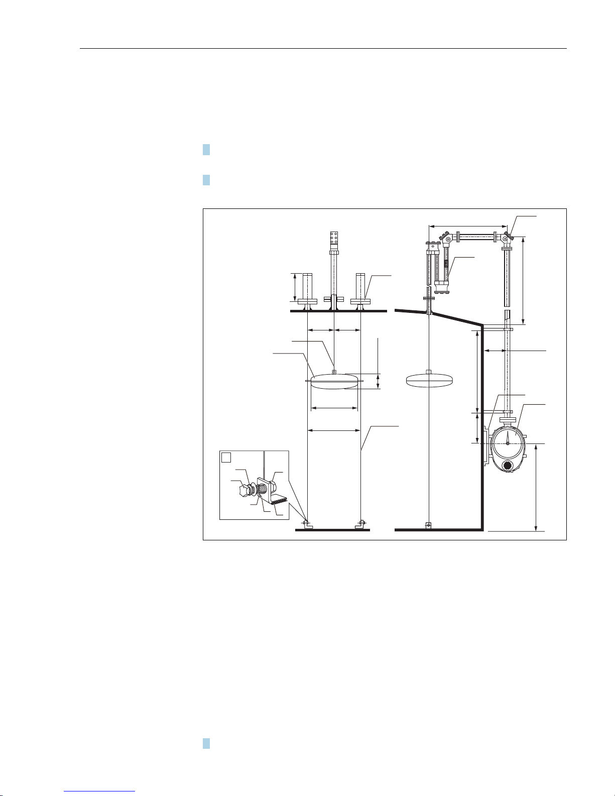
3.14 Liquid sealant for seal pot
3.14.1 Filling seal pot with liquid sealant when installing new LT
Liquid sealant filling procedure
1. Install entire LT unit including the seal pot and float into the tank.
• Parts of the drawing shown below may vary, depending on order code selected by customers.
2. Hoist the float up and down manually to confirm that the dial (or counter) display changes
accordingly.
Figure 43: LT with seal pot
A Anchor hook
1. Top anchor
2. Measuring tape
3. float
4. Guide wire
5. Nut
6. Wetting part (wetting to the tank)
7. Anchor hook
8. Guide wire
9. Bolt
10. Washer
11. Seal pot
12. 90° sheaves elbow
13. Gauge supporter
14. Gauge head
3. After LT operation check, remove the sheave elbow cover and fill with liquid sealant.
230
(9.06)
950 (37.4)
A
5
6
7
8
9
10
440
(17.32)
220
(8.66)
220
(8.66)
250 (9.84)
2000 - 3000
(78.74 - 118.11)
300
(11.81)
109 (4.29)
Ø400
(15.74)
1200 (47.24)
1200 (472.4)
1
2
3
4
11
12
13
14
3 Installation
Page 54
Float level gauge LT5
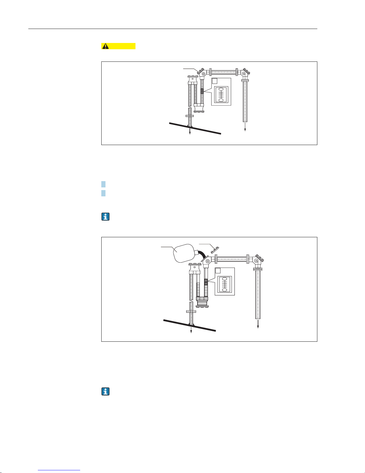
54 Endress+Hauser
After administering liquid sealant and checking LT operation, the liquid sealant may
leak into the tank through the measuring tape.
Figure 44: Filling seal pot with liquid sealant
A Liquid sealant indicator
BTo LT5
CTo inside the tank
1. 90° sheaves elbow
4. Administer liquid sealant until it comes up to the center of the indicator.
5. Replace 90° sheave elbow cover.
This completes the liquid sealant filling procedure.
2ℓ (liter) of liquid sealant is contained in the kit. When administering the proper amount of liquid
sealant, a small amount will remain in the bottle. Do not dispose remaining liquid sealant. It is
used as needed, following running LT.
Figure 45: Amount of liquid sealant
A Liquid sealant indicator
BTo LT5
CTo inside the tank
1. Liquid sealant
2. 90° sheaves elbow cover
If the tank is run without liquid sealant, LT seals, O-rings, or sheave elbows may be damaged by
gas contained the tank, and may cause LT to malfunction. Be sure to administer liquid sealant
prior to tank operation.
CAUTION
1
A
B
C
1
2
A
B
C
3 Installation
Page 55
Float level gauge LT5
Endress+Hauser 55
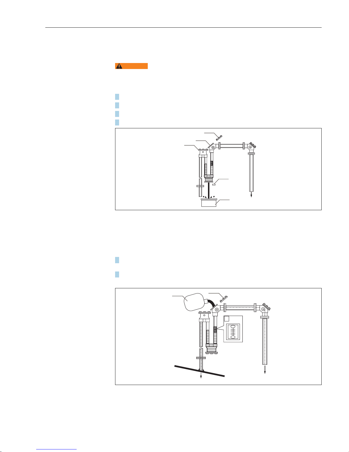
3.14.2 Filing seal pot with liquid sealant for installed LT
Liquid sealant filling procedure
• Do not allow used liquid sealant to contact hands or skin. If used liquid sealant mingles with liquid
from the tank, it may be come a hazardous substance.
• Exercise caution against substance from containers which used to drain liquid sealant.
1. Prepare a container for 2 ℓ (liter) or more and place under the sheave elbow outlet.
2. After confirming the safety of the vicinity around the tank, remove the seal pot drain bolt.
3. Drain the liquid sealant from the seal pot.
4. Remove the cover of the 90sheave elbow.
Figure 46: Draining seal liquid
ATo LT5
1. Sheaves elbow
2. 90° sheaves elbow
3. 90° sheaves elbow cover
4. Drain plug
5. Container for 2
ℓ or more
5. Tighten the drain bolt and fill until liquid sealant reaches the center of the indicator on the seal
pot side.
6. Replace the sheave elbow.
This completes the filling seal liquid procedure.
Figure 47: Filling seal liquid
A Liquid sealant indicator
BTo LT5
CTo inside the tank
1. Liquid sealant
2. 90° sheaves elbow cover
WARNING
1
2
3
A
4
5
1
2
A
B
C
3 Installation
Page 56
Float level gauge LT5
56 Endress+Hauser
4Display
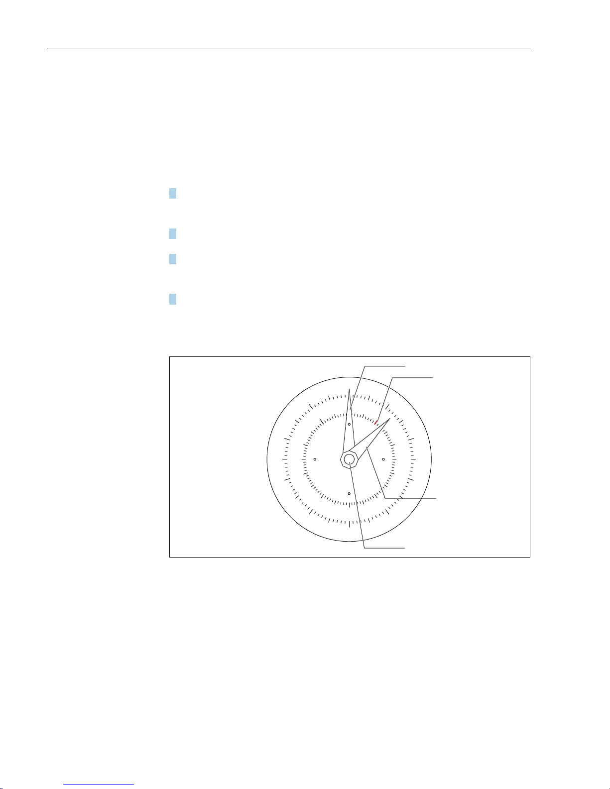
4.1 Dial display
Pointer setting and scale reading procedure
When calibrating (pointer setting) to authorized value as calculated value or measured value, calibrating procedure will depend on which display type is used. Use the dial type display when tank height is
20 m or less, and use the counter type display when tank height is 20 m or more.
1. Remove the indication cover and loosen the cap nut.
• The long indicator needle (white) can be turned freely, whereas the short one (green-yellow)
can be freed by pulling it.
2. Align the short needle with inner scale (1 mm/one scale), as it corresponds to lower value in liquid level.
3. Align the long needle with the outer scale.
• As one scale notch corresponds to 100 mm, the outer scale is aligned visually, according to the
lower two digits in liquid level value.
4. After aligning the needles, tighten the cap nut firmly.
• Long indicator needle (outer scale): 10000 mm, 1000 mm, 100 mm values; Short indicator
needle (inner scale): 10 mm, 1 mm values.
This completes the setting and reading procedure.
Figure 48: Dial display
1. Long indicator needle (white)
2. Set the needle to 1/10 when the needle is positioned at 10 mm.
3. Short indicator needle (green)
4. Cap nut
0
90
20
30
40
50
60
70
80
1
23
4
10
1
2
3
4
4 Display
Page 57
Float level gauge LT5
Endress+Hauser 57
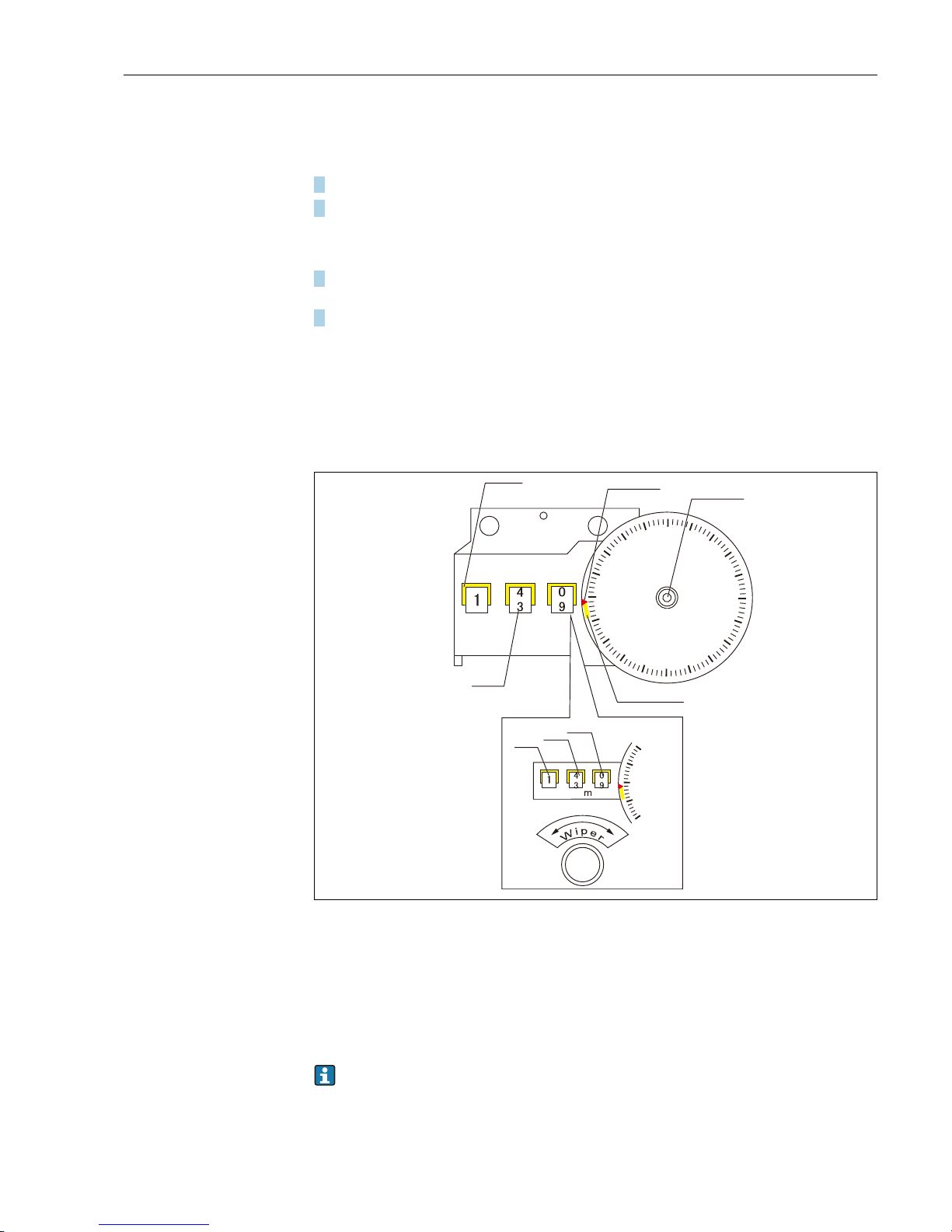
4.2 Counter display
Counter display procedure
1. Remove the indicator cover.
2. Loosen the screw at the center of the scale plate.
• The scale plate can rotate freely (1 scale notch is equivalent to 1 mm.).
• The counter changes one digit for every notch (100 mm) the scale plate moves.
3. Rotate the scale plate and align the numerical value of the counter to the three upper digits values
of liquid level.
4. Align the scale plate to the pointer which corresponds to the two lower digit values in liquid level,
then tighten the scale plate screw.
• If the pointer is indicating a range of between 97 and 03 on the scale plate, as in the figure
below, the counter will not change instantly. As it changes gradually, keeping constant the
relation between the rotation of the scale plate and numerical change, the counter will display
half values. Thus, in order to rule out incorrect reading, the counter window and parts of the
scale plate are correlated by color.
This completes the counter display procedure.
Figure 49: Counter display
1. Counter (yellow)
2. Counter (black)
3. Pointer (red)
4. Screw
5. Range (yellow)
6. First drum
7. Second drum
8. Third drum
Read the value of the range of the yellow counter when the red pointer points to the range of the
yellow and read the value of the black counter when it points to black counter.
(e.g.)
Yellow: 14000 mm
Black: 13999 mm
m
30
35
40
45
50
55
60
65
70
75
80
85
90
95
00
05
10
15
20
25
90
95
00
05
10
1
2
3
4
6
7
8
5
4 Display
Page 58
Float level gauge LT5
58 Endress+Hauser
4.3 Indication adjustment
Following are the three universal procedures for indicator adjustment, however the operation of the
indication can be performed by using all the same procedures.
• Fill the tank with actual liquid and calibrate the indicator to measured volume.
• With the tank empty, calibrate the indicator using formulaic calculations.
• Fill the tank with water and calibrate the indicator to measured volume.
4.3.1 Calibration using actual measuring liquid
In order to obtain a reliable value, measure the liquid level two or three times, using a measuring tape
which has been officially tested accurate to within ±0.3 mm/m (±1.2mm/10 m). Calibrate to the values only after accurate data has been gathered.
4.3.2 Calibration through calculation for empty tank
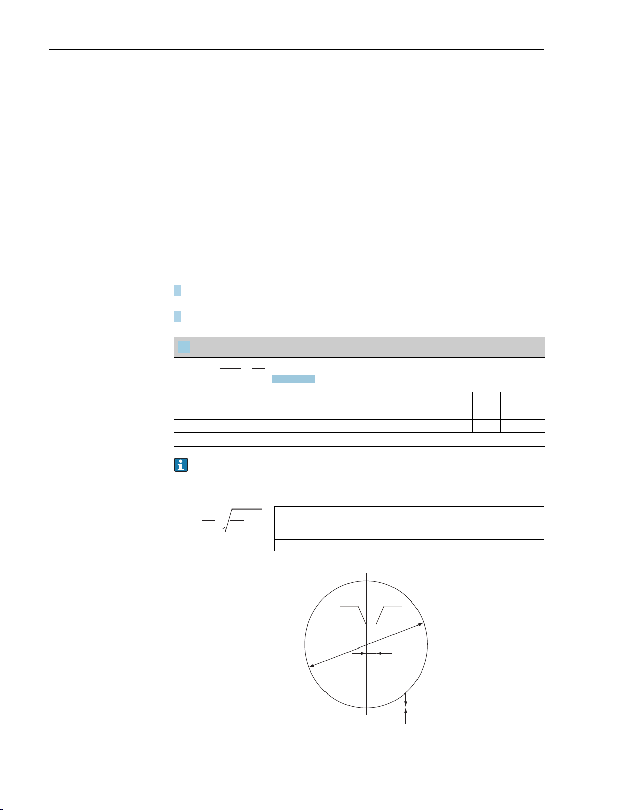
1. When the tank is empty, calculate the liquid level Lƒ using the following formula and set indicator
to the determined value.
2. When liquid reaches to the value of Lƒ, the float gains buoyancy and LT will show proper liquid
level.
Assign specific density to the formula above.
When float is installed in a spherical tank, where it will tend to deviate off center, find Lx in the formula
below and add it to the product of Lƒ in formula 2 above.
Figure 50: Setting indicator of spherical tank
1. Center of the tank
2. Center of the float for mounting
Draft of the float when tank is empty
Dimension of float D 400 mm Height of float h 200 mm
Weight of float W 8300 g Volume of float V 19200 cm
3
Cross section area of draft line S 1256.64 cm
2
Tension of tape T 1200 g
Density of actual liquid ρ 1 g/cm
3
(if empty = water)
1.
h
2
Lf =
+
S
V
2
W - T
ƽ
= 80.11 mm
Lx
=
D
2
-
- S
2
D²
4
Lx
Correction amount of liquid level indication by deviation caused by
float installation (mm)
D Diameter of spherical tank (mm)
S Deviation distance from center of tank to center of float (mm)
D
S
Lx
12
4 Display
Page 59
Float level gauge LT5
Endress+Hauser 59
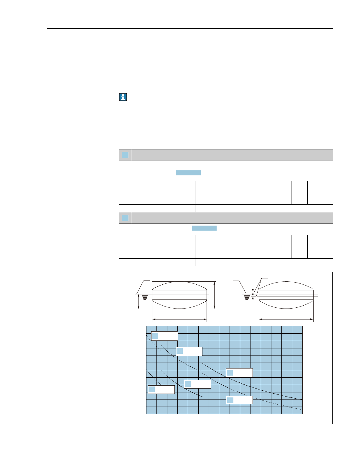
4.3.3 Calibration water filling procedure
When LT installation is complete, the water filling test is generally performed. Since measuring for
level is usually more difficult with other liquids, calibrating to water is recommended. The indicator will
be calibrated one again when the tank is filled with a commodity liquid. Using the following formula,
calculate the difference between where the float gains buoyancy in both water and commodity liquid.
Then correct the indicator value with water in the tank before filling it with a commodity liquid.
After setting the LT indicator to the measured value for water, determine LB in the formula
above. If the value of LB is a positive integer, add that value to the determined indicator value. If
the value of L is a negative integer, subtract that value from the determined indicator value. This
will be the final indicator value.
Calculation of 5000 g/Ø400 mm float for LT5-1
The following values show one of the typical example. Change a value which substitutes to the formula
depending on the specification required.
Figure 51: Graph of Ø400 float: Liquid density (g/cm3) for LT5-1, Unit: mm (in)
1. Draft on the density ρ
2. Water (draft on the density 1.0 g/cm
3
)
Draft of the float when tank is empty
Dimension of float D 400 mm Height of float h 109 mm
Weight of float W 5000 g Volume of float V 10520 cm
3
Cross section area of draft line S 1256.64 cm
2
Tension of tape T 1200 g
Density of actual liquid ρ 1 g/cm
3
(if empty = water)
Correction of the indicated value when filing water in tank
Dimension of float D 400 mm Height of float h 109 mm
Weight of float W 5000 g Volume of float V 10520 cm
3
Cross section area of draft line S 1256.64 cm
2
Tension of tape T 1200 g
Density of actual liquid ρ 0.8 g/cm
3
(actual liquid)
1.
h
2
Lf =
+
S
V
2
W - T
ƽ
= 42.88 mm
2.
= 7.56 mmLb = Lf (Water) + Lf (Actual liquid)
30
40
50
60
70
80
90
-30
-20
-10
0
10
20
30
0.5 1.0 1.5 2.0
1.
4.2 kg: L
B
1.
4.2 kg: Lf
5.0 kg: L
B
2.
5.0 kg: Lf
2.
8.0 kg: Lf
3.
8.0 kg: L
B
3.
Lf (mm)
L
B
(mm)
Ø400 (15.74)
Lf
Ø400 (15.74)
1
1
2
L > 0
B
L < 0
B
109 (4.29)
4 Display
Page 60
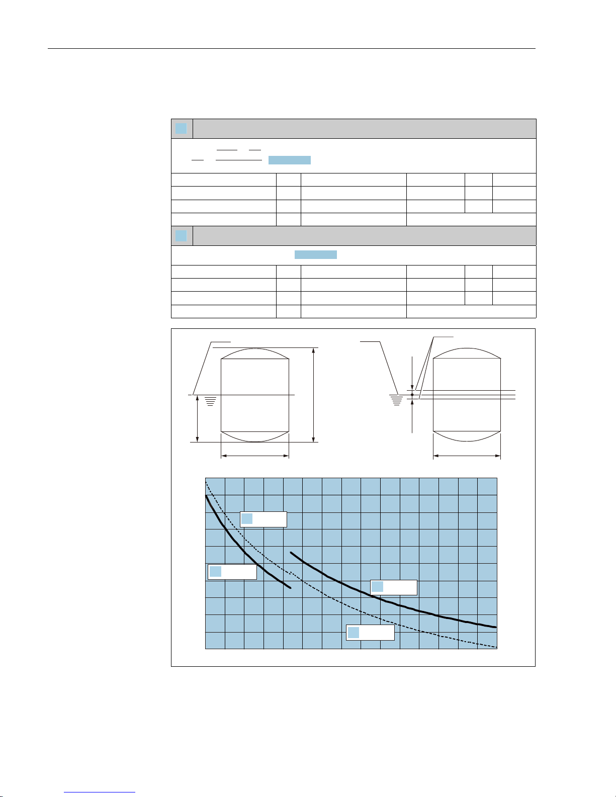
Float level gauge LT5
60 Endress+Hauser
Calculation of 2100g/Ø140 mm float for LT5-1
The following values show one of the typical example. Change a value which substitutes to the formula
depending on the specification required.
Figure 52: Indicator value for Ø140 float
1. Draft on the density ρ
2. Water (draft on the density 1.0 g/cm
3
)
Draft of the float when tank is empty
Dimension of float D 140 mm Height of float h 200 mm
Weight of float W 2100 g Volume of float V 2661.2 cm
3
Cross section area of draft line S 153.94 cm
2
Tension of tape T 1200 g
Density of actual liquid ρ 1 g/cm
3
(if empty = water)
Correction of the indicated value when filing water in tank
Dimension of float D 140 mm Height of float h 200 mm
Weight of float W 2100 g Volume of float V 2661.2 cm
3
Cross section area of draft line S 153.94 cm
2
Tension of tape T 1200 g
Density of actual liquid ρ 1 g/cm
3
(actual liquid)
1.
h
2
Lf =
+
S
V
2
W - T
ƽ
=73.02 mm
2.
= 14.61 mmLb = Lf (Water) + Lf (Actual liquid)
䚷
40
50
60
70
80
90
100
110
120
130
140
0.5 1.0 1.5 2.0
-40
-30
-20
-10
0
10
20
30
40
50
60
1
1
2
Lf
䚷
L
B
> 0L
B
< 0
Ø140 (5.51) Ø140 (5.51)
1.
2.1 kg: L
B
1.
2.1 kg: Lf
2.4 kg: Lf
2.
2.4 kg: L
B
2.
L
B
(mm)
Lf (mm)
200 (7.87)
4 Display
Page 61
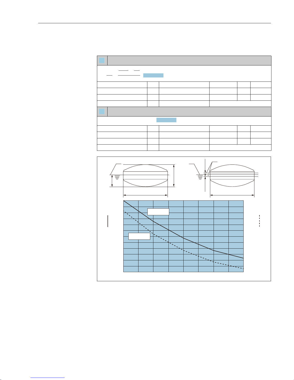
Float level gauge LT5
Endress+Hauser 61
Calculation of 8300g/Ø140 mm float for LT5-4/LT5-6
The following values show one of the typical example. Change a value which substitutes to the formula
depending on the specification required.
Figure 53: Graph of Ø400 float: Liquid density (g/cm3) for LT5-4 and LT5-6, Unit: mm (in)
1. Draft on the density ρ
2. Water (draft on the density 1.0 g/cm
3
)
Draft of the float when tank is empty
Dimension of float D 400 mm Height of float h 200 mm
Weight of float W 8300 g Volume of float V 19200 cm
3
Cross section area of draft line S 1256.64 cm
2
Tension of tape T 1200 g
Density of actual liquid ρ 1 g/cm
3
(if empty = water)
Correction of the indicated value when filing water in tank
Dimension of float D 400 mm Height of float h 200 mm
Weight of float W 8300 g Volume of float V 19200 cm
3
Cross section area of draft line S 1256.64 cm
2
Tension of tape T 1200 g
Density of actual liquid ρ 1 g/cm
3
(actual liquid)
1.
h
2
Lf =
+
S
V
2
W - T
ƽ
= 80.11 mm
2.
= 7.56 mmLb = Lf (Water) + Lf (Actual liquid)
Ø400 (15.74)
Lf
Ø400 (15.74)
1
1
2
L > 0
B
L < 0
B
80
90
100
110
120
130
20
10
30
40
50
60
0.5 0.6 0.7 0.8 0.9
8.3 kg: Lf
8.3 kg: L
B
Lf (mm)
L
B
(mm)
200 (7.87)
4 Display
Page 62

Float level gauge LT5
62 Endress+Hauser
4.3.4 LT startup and handling precautions for water and airtightness test
If misshapes occur, such as the damage to measuring tape while inside spherical tanks (i.e. tanks for
liquefied gas), tank operation and recovery costs can be extensive. It has been our experience, that
most issues involving measuring tape failures arise during test operation or in initial operation of the
tank. To prevent such incidents, be sure to complete the following procedures. By taking these preventive steps, misshapes can be avoided early on.
1. For high pressure tanks, be sure to keep the plug gate valve open and set the tank level gauge to
measurement mode. Failure to open the valve may result in measuring tape failure.
• If the valve is not open while filling tank with water, drain the water or remove the sheave
elbow cover. Then, stop the measuring tape by hands, open the valve gradually and reel the
measuring tape to LT.
2. For the water test, open the water-feed valve partially and supply water to a depth of 500 to
1000mm.
3. Large amount of water may damage the measuring tape. If the float is in close proximity to an
inlet, install the wave guard so float is unaffected.
4. If test for airtightness is performed while opening the gate valve, make sure the following components are firmly tightened.
• Drain plug on the bottom of LT
• Rear cover bolts
• Gland of gauge head rear cover
• Sheave elbow covers
If these items are not secure, large volumes of air may discharge from the system, causing
vibrations that will damage the measuring tape.
5. When opening LT rear cover upon completion of airtightness check test, confirm that the inner
tank is either at atmospheric pressure or that the gate valve is closed before opening LT.
• Do not open LT or sheave elbow covers to abruptly discharge compress ion built up by the air-
tightness check test. This will damage the measuring tape.
6. Be sure to open the gate valve when filling tank with commodity liquids such as liquefied gas.
• Closing the gate valve must be restricted almost exclusively to the emergencies or to period of
maintaining liquid level.
4 Display
Page 63
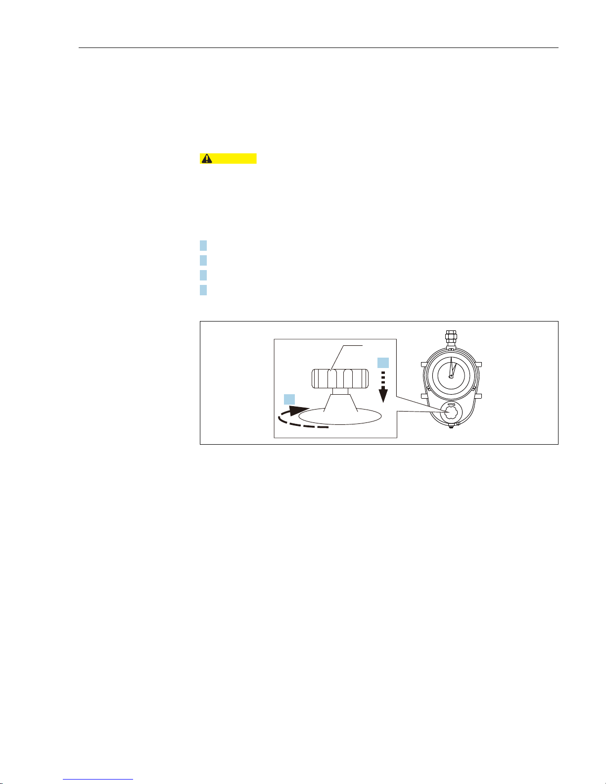
Float level gauge LT5
Endress+Hauser 63
5Operation
5.1 Check handle
This is used in order to check that a gauge operates properly.
• Checking gauge performance using the check handle, only after filling the tank with liquid.
• The check handle is not a float hoisting handle. Do not forcibly hoist the float using the check han-
dle.
• Refer to "5.2 Handling of Hoisting Handle" for details on using the hoisting handle.
Check handle using procedure
1. Push the check handle, attached to the bottom of LT, inside LT.
2. Push the check handle while rotating the check handle to the right.
3. Rotate the check handle to the left when indicator is approx. 4 to 5mm over scale.
4. Check the LT indicator.
This completes the check handle using procedure.
Figure 54: Check handle
1. Check handle
CAUTION
1.
2.
1
5 Operation
Page 64
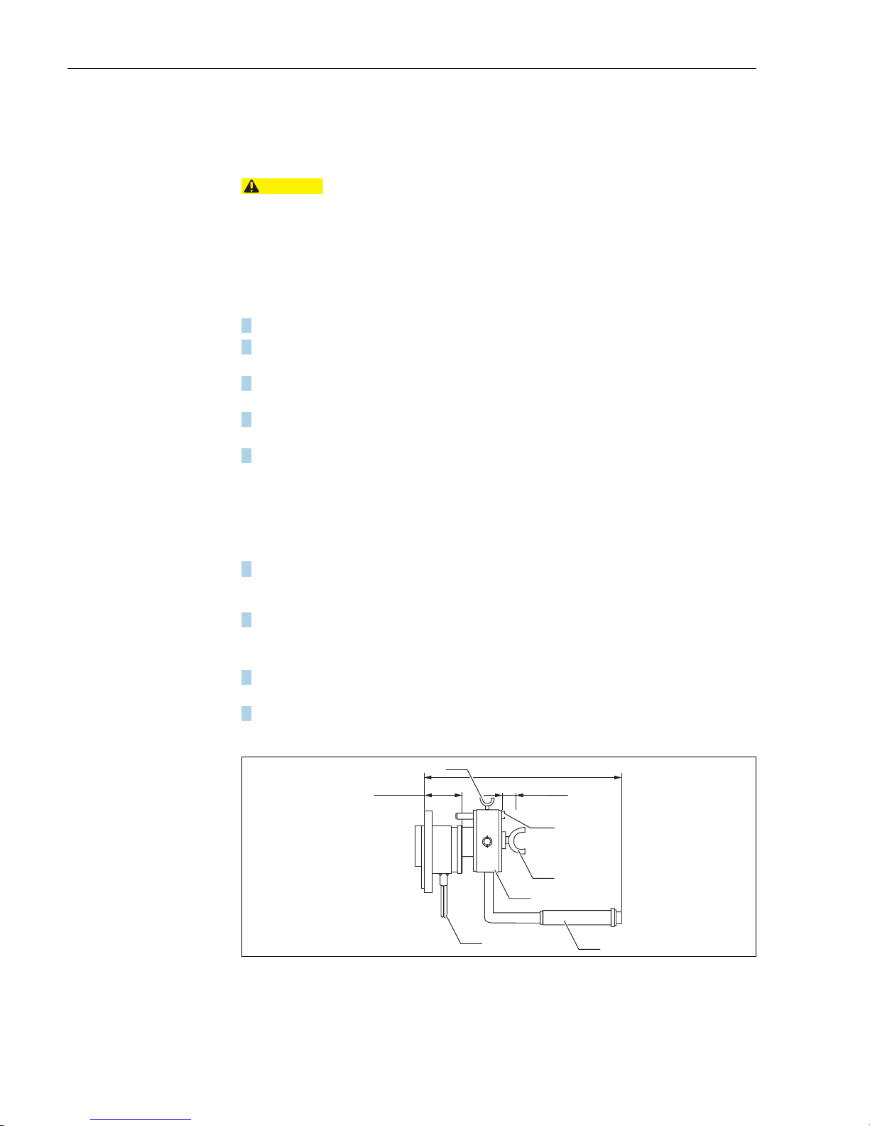
Float level gauge LT5
64 Endress+Hauser
5.2 Hoist unit (LT5-1)
The hoist handle is used to hoist up float when not in use. This helps to add life to LT when utilized for
tanks with a stirrer and/or for tanks containing corrosive liquid.
• Do not release grip on hoist handle, when hoisting or lowering the float. Doing so may cause float
to fall resulting in severe damage to float.
• When lowering the float, do not continue rotating handle after it reaches liquid surface.
• When handle reaches the A position, shown in Figure 50, the float is freed from the handle. Remove
the handle while float is in use.
Hoist up procedure
1. Secure the handle to the knob, using the wing bolt.
2. Push the knob while pulling the handle. Release the handle when the knob is pushed into position
B.
3. After confirming that the knob is secure in position B, rotate the handle counter clockwise for one
rotation, within 2 seconds.
4. To stop in the middle of hoisting, push the stopper to the deepest possible depth and secure the
win bolt.
5. Put the handle back slowly and push the stopper against LT body.
• The float will not fall by releasing handle.
• Remove the handle when hoist operation is complete.
This completes the hoist procedure.
Hoist down procedure
1. Insert the handle into the knob and fix it as shown below, rotate it counter clockwise, and then
loosen the win bolt. Secure the stopper with the win bolt after returning the stopper to original
position.
2. Rotate the handle clockwise.
• When the float reaches the liquid surface, the handle decreases suddenly and the LT indicator
will stop. Do not rotate the handle any further.
3. After completion of lowering float, pull the knob, pulling the handle, and release the knob when
the knob is in the condition A.
4. Remove the handle when lowering operation is complete.
This completes the lowering procedure.
Figure 55: Hoist unit for LT5-1
1. Win bolt
2. Stopper
3. Win bolt 2
4. Knob
5. Handle
6. Handle
CAUTION
50 (1.97)
210 (8.28)
B
10 (0.39)
A
1
2
3
4
5
6
5 Operation
Page 65
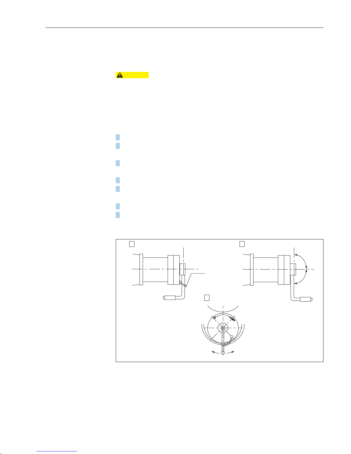
Float level gauge LT5
Endress+Hauser 65
5.3 Hoist unit (LT5-4/LT5-6)
The hoist handle is used to hoist up float when not in use. This helps to add life to LT when utilized for
tanks with a stirrer and/or for tanks containing corrosive liquid.
• Do not release grip on hoist handle, when hoisting or lowering the float. Doing so may cause float
to fall resulting in severe damage to float. If the handle must be released when hoisting float, lock
the handle first.
• Do not tilt the handle over 90 degrees or more toward its axis. This may cause the damage to the
float, measuring tape, or conster.
• Do not continue rotating the handle after float reaches liquid surface.
Hoist Up and Down Procedure
1. Remove the lock chain.
2. Slowly rotate handle in smooth circles (refer to previous page).
• The tape drum gear and the hoist shaft gear will begin to engage at 90 degrees.
3. Rotate handle to position B, turn handle counter clockwise, and hoist or lower float.
• After hoisting float, do not leave hand. Be sure to secure it with the lock chain first (refer to C).
4. Remove lock chain when lowering float.
5. Rotate handle clockwise to lower float.
• When float reaches the liquid surface, the indicator or counter will stop at current liquid level.
6. After lowering float, rotate handle 180 degrees against shaft to enable liquid to be measured.
7. While the float in service, loop lock chain 1 to 2 times around crank handle and place chain hock
on the loop nearest the screw (refer to A).
This completes the hoist and lowering of float procedure.
Figure 56: Hoist handle (LT5-4/LT5-6)
A During measurement
B While hoisting up and down
CFront view
a Deviated position of gears
b Engagement position of gears
c Hoisting float
d Lowering float
1. Lock chain
CAUTION
㼁㻼
㻰㻻㼃㻺
A
B
C
a
b
c
1
d
5 Operation
Page 66
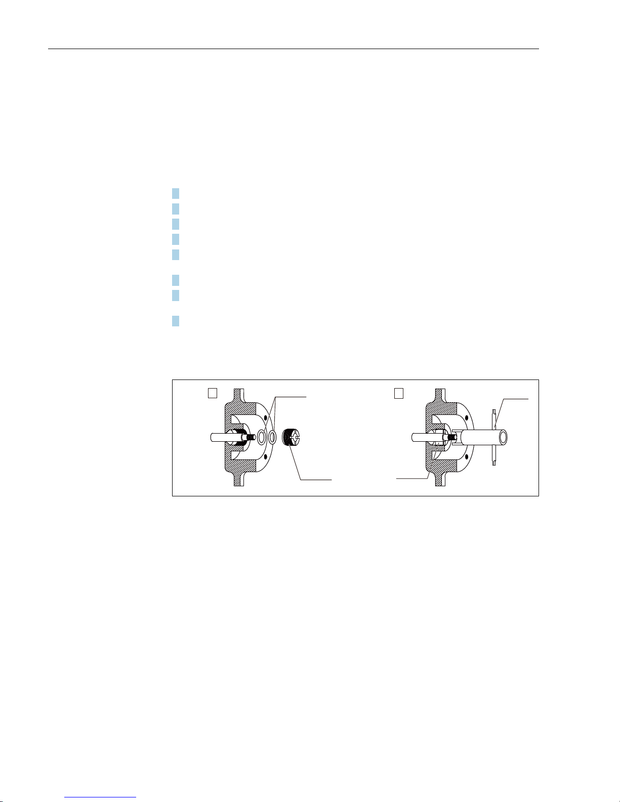
Float level gauge LT5
66 Endress+Hauser
6 Parts replacement
6.1 Replacement of O-ring for transmitter (LT5-4/LT5-6)
If gas begins leaking from the side of LT body, O-rings must be replaced.
The following steps must be performed carefully due to the tank being under pressure from within.
Replacement procedure
1. Close the gate valve at the top of the tank.
2. Gradually discharge all remaining pressure in the pipe.
3. Remove the attached disc.
4. Remove the transmitter if attached.
5. Remove coupling from the side of LT and remove gland and O-rings (2pcs.) by using a gland fixing
tool.
6. Inspect the other components. Replace O-rings and other wear items as necessary
7. Replace O-rings, tighten gland and assemble transmitter according to steps above in reverse
order.
8. Open gate valve gradually.
• Opening gate valve abruptly will release a sudden burst of air from the system, which may
result in the damage to the measuring tape.
This completes the replacement procedure.
Figure 57: O-ring replacement
A Before tightening gland
B After tightening gland
1. O-ring
2. Gland
3. Gland fixing tool
A
B
1
2
2
3
6 Parts replacement
Page 67
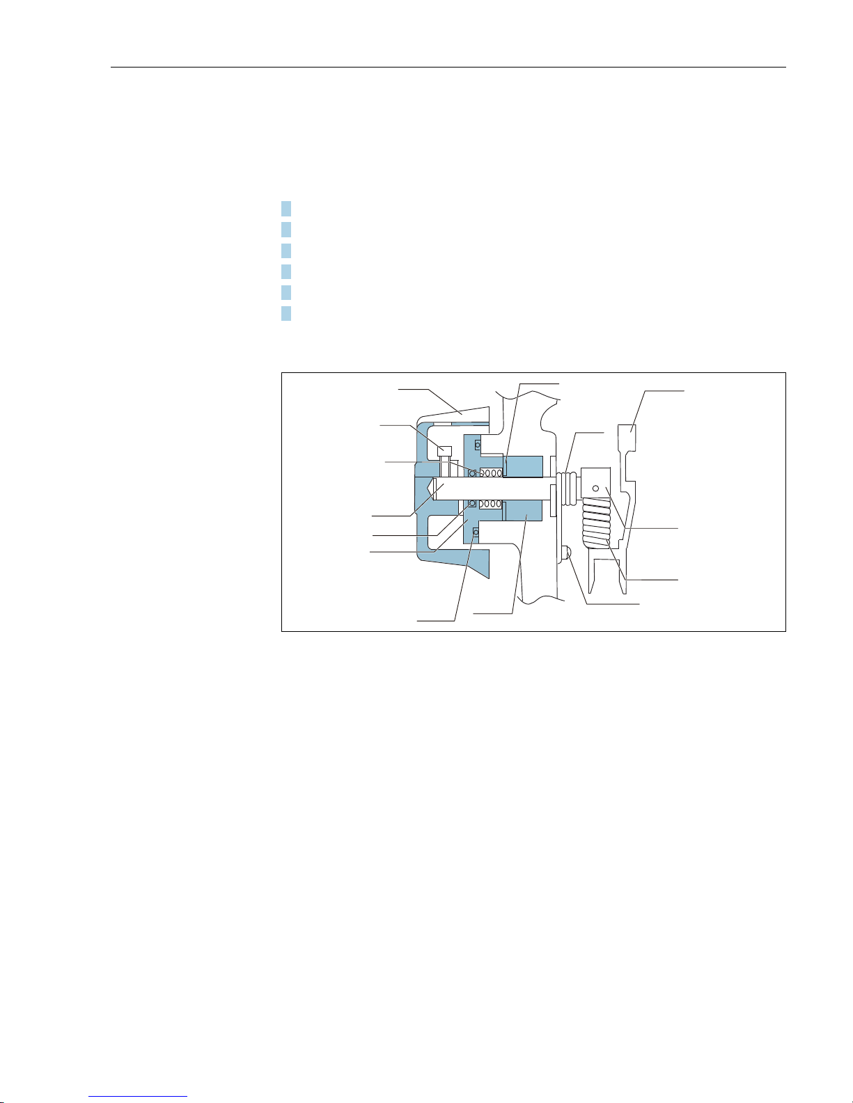
Float level gauge LT5
Endress+Hauser 67
6.2 Drive check replacement (LT5-4/LT5-6)
The drive check system is essential to confirming LT operation and employed frequently, causing inevitable wear and tear, but is designed to be easily repaired and serviced.
Replacement procedure
1. Remove LT rear cover and tape drum.
2. Loosen socket head cap screw of the check handle and remove check handle.
3. Remove gland clamp, using a spanner or crescent wrench (nominal 46).
4. Remove gland spring, collar, seal metal.
5. Pull check shaft out toward the tape drum.
6. After completing parts replacement, assemble drive check according to steps above in revers
order.
This completes the replacement procedure.
Figure 58: Parts name of drive check unit
1. Tape drum
2. Check spring
3. Check boss
4. Spring
5. Spring set screw
6. Seal metal
7. O-ring
8. Gland clamp
9. O-ring
10. Check shaft
11. Gland spring
12. Socket head screw
13. Check handle
14. Collar
1
2
3
4
5
6
7
8
9
10
11
12
13
14
6 Parts replacement
Page 68
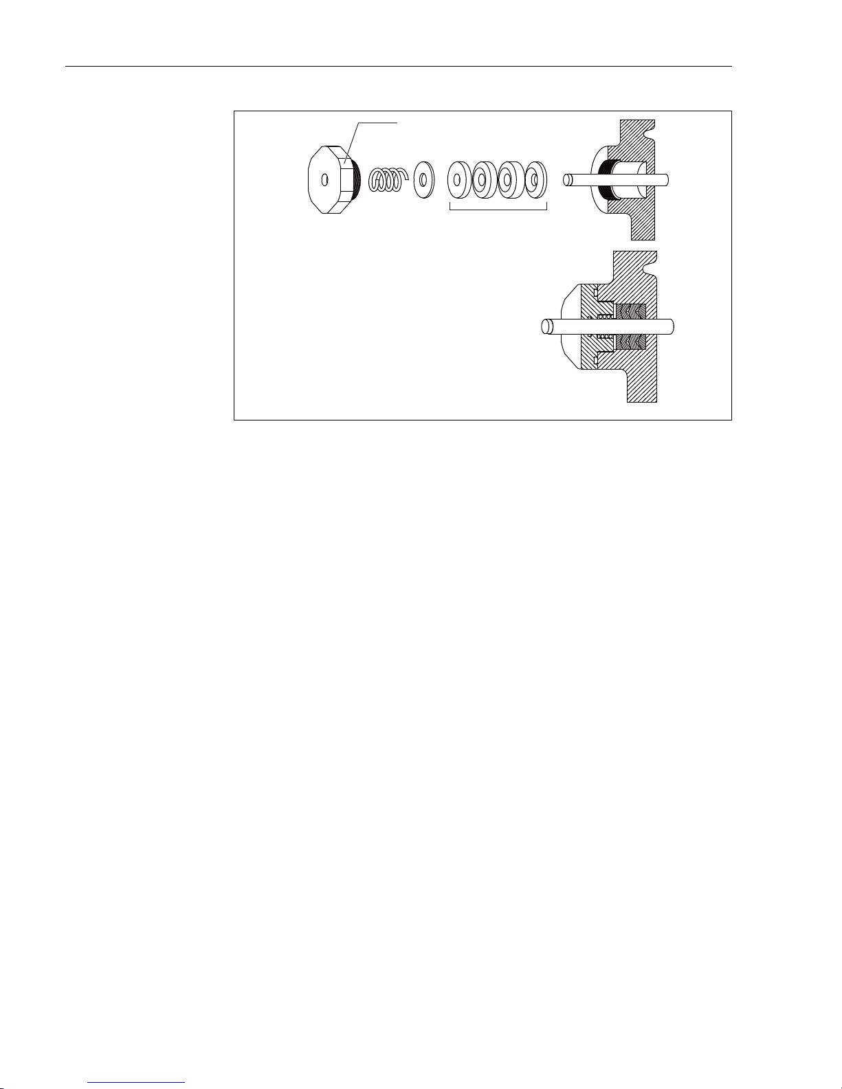
Float level gauge LT5
68 Endress+Hauser
Figure 59: Drive check unit
1. Gland clamp
2. Seal metal
1
2
6 Parts replacement
Page 69
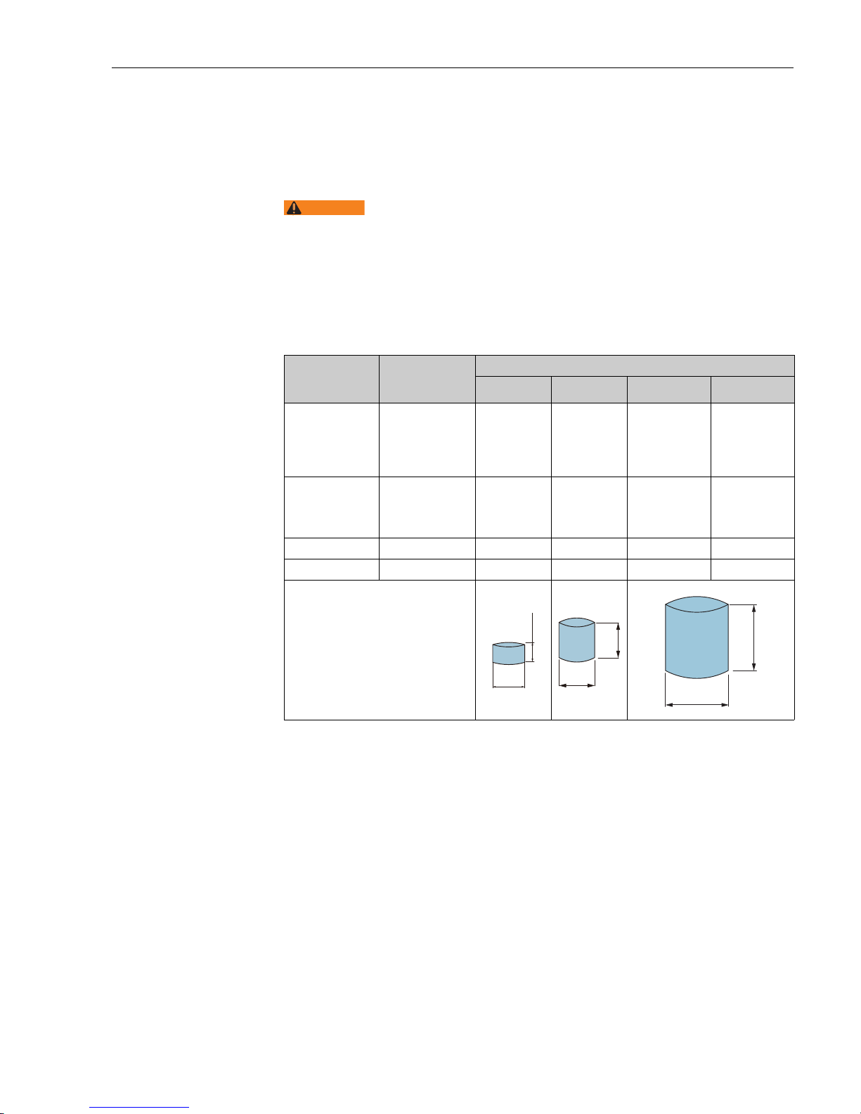
Float level gauge LT5
Endress+Hauser 69
7 Maintenance
7.1 Precaution prior to maintenance
• Use due vigilance when working with flammable liquid tanks. Allow flammable liquids plenty of
time to diffuse before pumping or transferring to tank (refer to the table below).
• Be sure to wear antistatic clothing, gloves, and safety shoes.
• Follow directions of the safety supervisor
Recommended standing time static from Electricity Safety Guideline (National Institute of
Industrial Safety)
Unit: m (ft)
Conductivity of
charging material
(S/m)
Flammable liquid
(example)
Volume of charging material (m3)
10 or less 10 to 50 50 to 500 5000 or grater
10
-8
or greater
Acetic acid
Ethanol
Ethyl chloride
Methanol
Light oil
1 min. or more 1 min. or more 1 min. or more 2 min. or more
10
-12
to 10
-8
Vinyl acetate
Toluene
Benzene
Gasoline
2 min. or more 3 min. or more 10 min. or more 30 min. or more
10-
14
to 10
-12
Methyl cyclohexane 4 min. or more 5 min. or more 60 min. or more 120 min. or more
10
-14
or less Carbon tetrachloride 10 min. or more 10 min. or more 120 min. or more 240 min. or more
WARNING
10 m
3
10 m
3
2.5
(8.2)
2
(6.57)
3.6
(11.81)
5
(16.4)
50 m
3
17.84
(58.53)
20
(65.62)
5000 m
3
7 Maintenance
Page 70
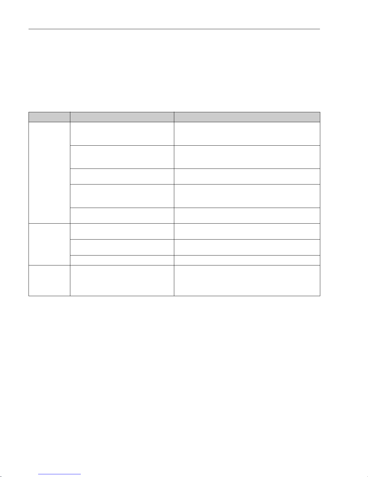
Float level gauge LT5
70 Endress+Hauser
7.2 Daily inspection
LT does not require any inspections after it has been properly installed in a tank.
7.3 Periodical inspection
Follow the table below to perform the periodical inspection.
Product/Part Check item Check procedure
Gauge Head
(for all LT)
Corrosion check and cleaning
of tape protective pipe
• After opening the gauge head rear cover, check accumulation of rust.
• If necessary, remove rust by tapping the protective pipe with a wooden
hammer.
Check of reduction gear engagement and bearing
• After removing the indicator cover, rotate the reduction gear to check
engagement and confirm that backlash is within 1 mm of indication.
• Check the bearing.
Friction on tape drum and sprocket
After opening the gauge head rear cover, check bearings of drums for
corrosion or dust. Clean them as needed.
Characteristic change of conster
• Check the level gauge operation with the drive check. If the measured
value is not stable, clean the conster.
• If the level gauge is not recovered, replace the conster.
Water drops and dimming on indicator window
Confirm the indicator cover is tightened firmly and there is no dust
contamination on the gasket.
Gauge Head
(LT5-4/LT5-6)
Check of drive check
Check the condition of the check spring inside the gauge head and its
performance.
Check of magnet coupling
Replace the sprocket to strip the rust and remove the dust (1 to 2 times in
a year).
Check of O-ring leak Check airtightness of LT with, using soap water.
Sheave Elbow Sheave elbow friction
• In sheave elbow, remove measuring tape from roller and check to
rotate smoothly.
• Remove bearing and check friction.
• Remove dust from roller.
7 Maintenance
Page 71

Float level gauge LT5
Endress+Hauser 71
8 Troubleshooting
8.1 Failure causes and countermeasures
Product/Part Check item Check procedure
Indication does not change
at all
• Breakage of measuring tape
• Guide wire caught
• Breakage of conster
• Drive check caught
• Wear and tear of gear which is connected to the
indication system
• Improper setting of sprocket or measuring tape
• Float sinking
• Open the tank and replace the measuring tape.
• After opening the tank, re-stretch the guide wire.
• Replace the conster.
• Open the rear cover of gauge head and repair or replace the
conster.
• Replace the entire gear unit of the indication system
• Check the gear after opening rear cover of gauge head.
• Replace the float after opening the tank
Frequent indication error
Deterioration of conster
Check variation of indication value and replace the conster if
deteriorated.
• Apply to items 2, 4, 5, 6 mentioned above.
• Loosening of indicator pointer
• Improper setting of tape guide
• Kink or twist of measuring tape
• Check the internal parts of the gauge head.
• Check lock nut for the indicator pointer after opening indica-
tor cover.
• Check the gap between the sprocket and tape guide.
• Pull measuring tape out and check after opening sheave
elbow cover. The measuring tape can be repaired depending
on the condition of it.
There is difference of value
between the indication of
measuring tape and the
indicator of the display.
• Some error found in the gauge head.
• No error found in the gauge head.
• Inspect the items mentioned above and have countermea-
sures.
• Failure by measuring liquid
• Negative influence by measuring technique
• Negative influence by sludge deposition
• Negative influence by strong wind
• Error of measuring scale
Check handle can not rotate
and return.
• Check shaft has rusted.
• Check driver spring is deteriorate.
• Clean up the shaft and replace entire check handle unit.
• Replace the spring.
Check handle can not rotate
and return.
• Check shaft has rusted.
• Check driver spring is deteriorate.
• Clean up the shaft and replace entire check handle unit.
• Replace the spring.
Drive check does not work.
(LT5-4/LT5-6)
• Loosening of set screw of check handle
• Breakage of check driver spring
• The spring gets stuck in the tape drum and can
not move.
• Tighten the set screw.
• Replace the entire check unit.
• Repair the check unit or replace the entire unit.
Gas leakage (LT5-4/LT5-6)
• Airtight leakage at the junction part of the rear
cover
• Airtight leakage of penetration part of the drive
check unit
• Replace the packing or apply the seal end agent to the junction part.
• Replace the seal metal.
8 Troubleshooting
Page 72

Float level gauge LT5
72 Endress+Hauser
9Repair
9.1 General information on repairs
The Endress+Hauser repair concept assumes that the devices have a modular design and that repairs
can be done by the Endress+Hauser service or specially trained customers.
Spare parts are contained in suitable kits. They contain the related replacement instructions.
For more information on service and spare parts, contact the Service Department at Endress+Hauser.
9.2 Repairs to Ex-approved devices
When carrying out repairs to Ex-approved devices, please note the following:
• Repairs to Ex-approved devices may only be carried out by trained personnel or by the
Endress+Hauser Service.
• Comply with the prevailing standards, national Ex-area regulations, safety instructions (XA) and
certificates.
• Only use original spare parts from Endress+Hauser.
• When ordering a spare part, please note the device designation on the nameplate. Only replace
parts with identical parts.
• Carry out repairs according to the instructions. On completion of repairs, carry out the specified routine test on the device.
• Only Endress+Hauser Service may convert a certified device into a different certified variant.
• Document all repair work and conversions.
9.3 Spare parts
Some interchangeable measuring device components are listed on an overview sign in the connection
compartment cover.
The spare part overview sign contains the following information:
• A list of the most important spare parts for the measuring device, including their ordering information.
• The URL for the W@M Device Viewer (www.endress.com/deviceviewer):
All the spare parts for the measuring device, along with the order code, are listed here and can be
ordered. If available, users can also download the associated Installation
Instructions.
9.4 Endress+Hauser service
Endress+Hauser provides various services.
Contact your Endress+Hauser Sales Center for information on service and spare parts.
9 Repair
Page 73

Float level gauge LT5
Endress+Hauser 73
9.5 Return
The measuring device must be returned if repairs or a factory calibration are required, or if the wrong
measuring device has been ordered or delivered. According to legal regulations, Endress+Hauser, as an
ISO-certified company, is required to follow certain procedures when handling returned products that
are in contact with medium.
To ensure swift, safe and professional device returns, please read the return procedures and conditions
on the Endress+Hauser website at www.services.endress.com/return-material
9.6 Disposal
Observe the following notes during disposal:
• Observe valid federal/national regulations.
• Ensure proper separation and reuse of the device components.
9 Repair
Page 74
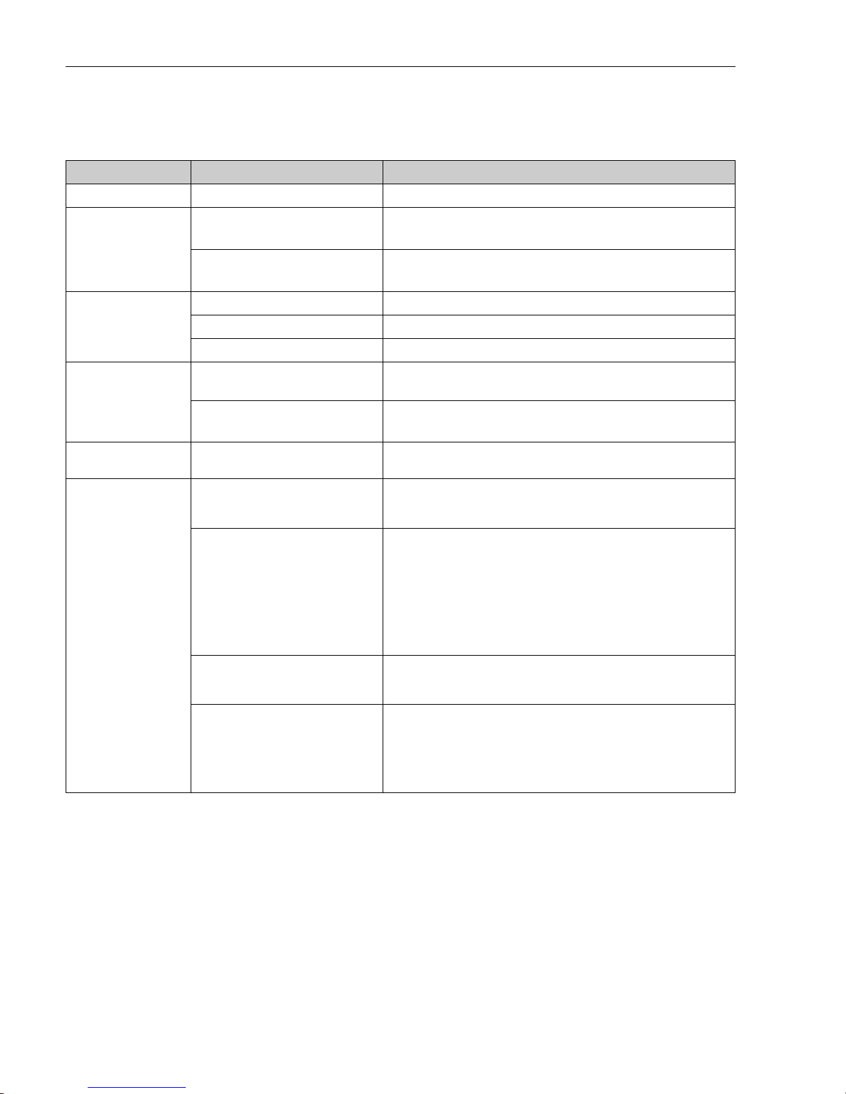
Float level gauge LT5
74 Endress+Hauser
10 Technical data
Item Product root Measuring range/Specification
Measuring range LT5 0 - 2.5, 5, 10, 16, 20, 30m 0 to 60ft, 100ft
Accuracy
Ø400 mm float
±2mm
(Under the condition of; specific Density: 1g/cm
3
,measuring range; 10m)
Ø140 mm float
±30mm
(Under the condition of; specific Density: 1g/cm
3
,measuring range; 10m)
Maximum operating
Pressure
LT5-1 0...0.1961bar/0.01961MPa/2.84psi
LT5-4 0...0.9807bar/0.09807MPa/14.22psi
LT5-6 0...24.5bar/2.45MPa/355.25psi
Operating temperature
limits
LT5-1
Wetted parts: -200....+200ºC
Gauge head: -20....+70ºC
LT5-4/LT5-6
Wetted parts: -45 to +80ºC
Gauge head: -20 to +70ºC
Display LT5
Two pointers or Counter (min. readable scale:1mm)
Counter only for 30m or 100ft
Process connection
LT5-1 threaded, low pressure
Rp 1-1/2, w/o union nut, thread JIS B0203
Rc 1-1/2, union nut, SUS316, thread JIS B0203
NPT 1-1/2, union nut, SUS316, thread ANSI
LT5-1 flange, low pressure
flange spec./material
10K 40A RF, Alu (AC4A), flange JIS B2220
10K 40A RF, SUS316, flange JIS B2220
NPS 1-1/2" Cl.150 RF, Alu (AC4A) flange ASME B16.5
NPS 1-1/2" Cl.150 RF, SUS316 flange ASME B16.5
40A 150lbs RF, Alu (AC4A), flange JPI 7S-15
40A 150lbs RF, SUS316, flange JPI 7S-15
10K 150A RF, SUS316, flange JIS B2220
NPS 6" Cl.150 RF, SUS316 flange ASME B16.5
150A 150lbs RF, SUS316, flange JPI 7S-15
LT5-4 (flange, medium pressure)
Flange spec./material
10K 40A RF, alu (AC4CT6), flange JIS B2220
NPS 1-1/2" Cl.150 RF, Alu (AC4CT6) flange ASME B16.5
40A 150lbs RF, Alu (AC4CT6), flange JPI 7S-15
LT5-6 (flange, high pressure)
Flange spec./Gauge material/Bolt
material
10K 40A RF, Iron, flange JIS B2220
NPS 1-1/2" Cl.150 RF, iron flange ASME B16.5
40A 150lbs RF, Iron, flange JPI 7S-15
20K 40A RF, Iron, flange JIS B2220
NPS 1-1/2" Cl.300 RF, iron flange ASME B16.5
40A 300lbs RF, Iron, flange JPI 7S-15
10 Technical data
Page 75
Float level gauge LT5
Endress+Hauser 75
SUS316 or PVC is an available option for float material in low pressure conditions.
Ø400 mm Weight ρ: Liquid Density (g/cm3)
Low pressure 4.2 kg 0.5 ≤ ρ < 0.65
Low pressure 5.0 kg 0.65
≤ ρ < 1.05
Low pressure 8.0 kg 1.05
≤ ρ ≤ 2.0
High pressure 8.3 kg 0.5 ≤ ρ ≤ 0.7
Ø140 mm Weight ρ: Liquid Density (g/cm3)
Low pressure 2.1 kg 0.5 ≤ ρ < 0.94
Low pressure 2.4 kg
0.94 ≤ ρ < 2.0
Item Product Coupling
Coupling
(Gauge head and display)
LT5-1 (Threaded/flange low pressure) Shaft
LT5-4 (Flange/medium pressure) Pressure bulkhead magnet coupling
LT5-6 (Flange/high pressure) Pressure bulkhead magnet coupling
Item Product Weight
Total weight
LT5-1 (Threaded/flange low pressure) Approximately 15 kg
LT5-4 (Flange/medium pressure) Approximately 22 kg
LT5-6 (Flange/high pressure) Approximately 100 kg
Item Product Color
Color
Gauge head E+H blue
Other components
Silver
10 Technical data
Page 76
Float level gauge LT5
76 Endress+Hauser
11 Materials defined by standards
Aluminum
Stainless steel
Others
Symbols Descriptions
ADC12 Aluminum Alloy Die Casting (SI-Si-Cu)
AC4CT6 Aluminum Alloy Casting (Si7Mg)
AC4A Aluminum Alloy Casting (Si10Mg)
Symbols Descriptions
SUS304 Stainless Steel (18Cr-8Ni)
SUS316 Stainless Steel (18Cr-12Ni-2.5Mo)
SCS13 Stainless Steel Cast Steel equivalent to SUS304
SCS14 Stainless Steel Cast Steel equivalent to SUS316
Symbols Descriptions
SGP Steel gas pipe
PVC Polyvinyl chloride
11 Materials defined by standards
Page 77

Float level gauge LT5
Endress+Hauser 77
Page 78

www.addresses.endress.com
 Loading...