

Page 1
Products Solutions Services
Operating Instructions
Liquisys M CLM223/253
Transmitter for Conductivity
BA00193C/07/EN/15.15
71300836
Page 2

Page 3

Liquisys M CLM223/253 Table of contents
Endress+Hauser 3
Table of contents
1 Document information .............. 5
1.1 Warnings ............................ 5
1.2 Symbols used .......................... 5
1.3 Symbols on the device ................... 5
1.4 Electrical symbols ...................... 6
2 Basic safety instructions ............ 7
2.1 Requirements for personnel ............... 7
2.2 Designated use ........................ 7
2.3 Occupational safety ..................... 7
2.4 Operational safety ...................... 8
2.5 Product safety ......................... 8
2.5.1 State of the art .................. 8
2.5.2 IT security ...................... 8
3 Incoming acceptance and product
identification ....................... 9
3.1 Incoming acceptance .................... 9
3.2 Scope of delivery ....................... 9
3.3 Product identification ................... 10
3.3.1 Nameplate .................... 10
3.3.2 Product identification ............ 10
3.4 Certificates and approvals ............... 10
3.4.1 mark ...................... 10
3.4.2 CSA General Purpose ............. 10
4 Installation ....................... 11
4.1 Installation at a glance .................. 11
4.1.1 Measuring system ............... 12
4.2 Installation conditions .................. 13
4.2.1 Field device .................... 13
4.2.2 Panel-mounted device ............ 14
4.3 Installation instructions ................. 15
4.3.1 Field device .................... 15
4.3.2 Panel-mounted device ............ 17
4.4 Post-installation check .................. 17
5 Electrical connection .............. 18
5.1 Wiring ............................. 18
5.1.1 Wiring diagram ................. 18
5.1.2 Measuring cables and sensor
connection .................... 21
5.2 Alarm contact ........................ 24
5.3 Post-connection check .................. 24
6 Operation options ................. 25
6.1 Quick operation guide .................. 25
6.2 Display and operating elements ........... 25
6.2.1 Display ....................... 25
6.2.2 Operating elements .............. 27
6.2.3 Key functions .................. 27
6.3 Local operation ....................... 29
6.3.1 Automatic/manual mode .......... 29
6.3.2 Operating concept ............... 30
7 Commissioning .................... 32
7.1 Function check ....................... 32
7.2 Switching on ......................... 32
7.3 Quick Setup .......................... 34
7.4 Device configuration ................... 37
7.4.1 Setup 1 (conductivity) ............ 37
7.4.2 Setup 2 (temperature) ............ 39
7.4.3 Current input .................. 42
7.4.4 Current outputs ................. 45
7.4.5 Alarm ........................ 49
7.4.6 Check ........................ 50
7.4.7 Relay configuration .............. 53
7.4.8 Temperature compensation with
table ......................... 69
7.4.9 Concentration Measurement ....... 70
7.4.10 Service ....................... 73
7.4.11 E+H Service .................... 75
7.4.12 Interfaces ..................... 76
7.4.13 Communication ................. 76
7.5 Calibration .......................... 77
8 Diagnostics and troubleshooting ... 81
8.1 Trouble shooting instructions ............. 81
8.2 System error messages .................. 81
8.3 Process-specific errors .................. 84
8.4 Device-specific errors ................... 88
9 Maintenance ...................... 90
9.1 Maintenance of the entire measuring point .. 90
9.1.1 Cleaning the transmitter .......... 90
9.1.2 Cleaning the conductivity sensors ... 91
9.1.3 Simulation of conductive sensors for
device testing .................. 91
9.1.4 Simulation of inductive sensors for
device testing .................. 92
9.1.5 Checking conductive sensors ....... 93
9.1.6 Checking inductive sensors ........ 94
9.1.7 Assembly ..................... 94
9.1.8 Connecting cables and junction
boxes ........................ 94
10 Repair ............................ 95
10.1 Spare parts .......................... 95
10.2 Disassembling the panel-mounted device .... 95
10.3 Disassembling the field device ............ 98
10.4 Replacing the central module ............ 102
10.5 Return ............................. 103
10.6 Disposal ........................... 103
Page 4

Table of contents Liquisys M CLM223/253
4 Endress+Hauser
11 Accessories ...................... 104
11.1 Sensors ............................ 104
11.1.1 Sensors with conductive
measurement of conductivity ...... 104
11.1.2 Sensors with inductive measurement
of conductivity ................ 104
11.2 Connection accessories ................. 105
11.3 Installation accessories ................ 105
11.4 Software and hardware add-ons .......... 106
11.5 Calibration solutions .................. 107
12 Technical data ................... 108
12.1 Input .............................. 108
12.2 Output ............................ 108
12.3 Power supply ........................ 112
12.4 Performance characteristics ............. 113
12.5 Environment ........................ 113
12.6 Mechanical construction ............... 114
13 Appendix ........................ 115
Index ................................. 120
Page 5
Liquisys M CLM223/253 Document information
Endress+Hauser 5
1 Document information
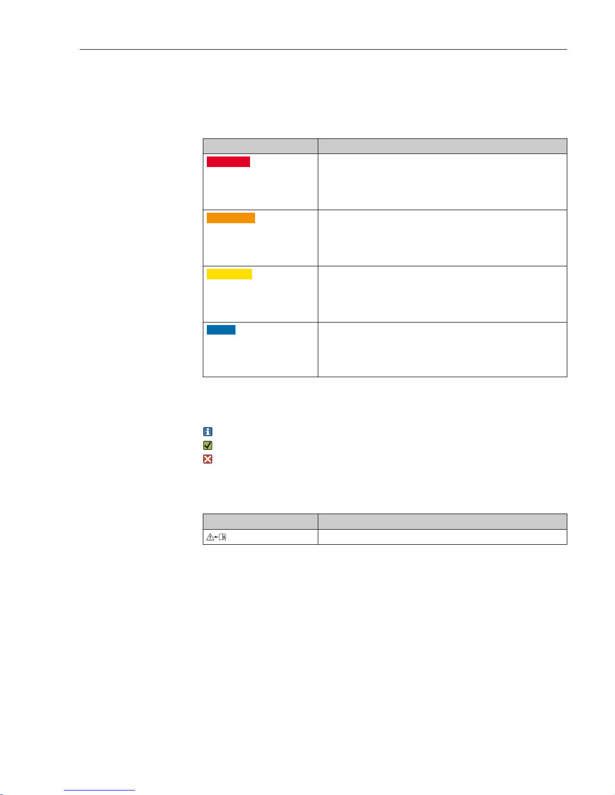
1.1 Warnings
Structure of information Meaning
L
DANGER
Causes (/consequences)
Consequences of non-compliance
(if applicable)
‣
Corrective action
This symbol alerts you to a dangerous situation.
Failure to avoid the dangerous situation will result in a fatal or serious
injury.
L
WARNING
Causes (/consequences)
Consequences of non-compliance
(if applicable)
‣
Corrective action
This symbol alerts you to a dangerous situation.
Failure to avoid the dangerous situation can result in a fatal or serious
injury.
L
CAUTION
Causes (/consequences)
Consequences of non-compliance
(if applicable)
‣
Corrective action
This symbol alerts you to a dangerous situation.
Failure to avoid this situation can result in minor or more serious injuries.
NOTICE
Cause/situation
Consequences of non-compliance
(if applicable)
‣
Action/note
This symbol alerts you to situations which may result in damage to
property.
1.2 Symbols used
Additional information, tips
Permitted or recommended
Forbidden or not recommended
1.3 Symbols on the device
Symbol Meaning
Reference to device documentation
Page 6
Document information Liquisys M CLM223/253
6 Endress+Hauser
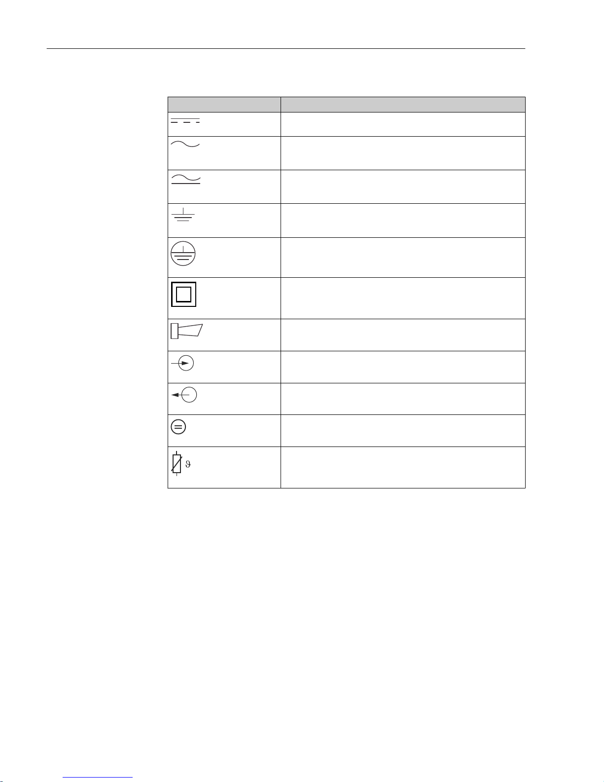
1.4 Electrical symbols
Symbol Meaning
A0027423
Direct current
A terminal at which DC is present or through which DC flows.
A0027424
Alternating current
A terminal to which alternating voltage (sine-wave) is applied or through
which alternating current flows.
A0027425
Direct current or alternating current
A terminal at which direct voltage or alternating voltage is present or
through which direct current or alternating current flows.
A0027426
Ground connection
A terminal which, from the user's point of view, is already grounded via a
grounding system.
A0027427
Protective ground connection
A terminal which must be connected to ground prior to establishing any
other connections.
A0019929
Class II equipment
Reinforced or double insulation
A0027420
Alarm relay
A0027428
Input
A0027429
Output
A0027430
DC voltage source
A0027431
Temperature sensor
Page 7

Liquisys M CLM223/253 Basic safety instructions
Endress+Hauser 7
2 Basic safety instructions
2.1 Requirements for personnel
• Installation, commissioning, operation and maintenance of the measuring system may
be carried out only by specially trained technical personnel.
• The technical personnel must be authorized by the plant operator to carry out the
specified activities.
• The electrical connection may be performed only by an electrical technician.
• The technical personnel must have read and understood these Operating Instructions
and must follow the instructions contained therein.
• Measuring point faults may be repaired only by authorized and specially trained
personnel.
Repairs not described in the Operating Instructions provided may only be carried out
directly by the manufacturer or by the service organization.
2.2 Designated use
Liquisys M is a transmitter for determining the conductivity and resistivity of liquid media.
The transmitter is particularly suited for use in the following areas:
• Ultrapure water
• Water treatment
• Cooling water desalination
• Condensate treatment
• Municipal wastewater treatment plants
• Chemical industry
• Food industry
• Pharmaceutical industry
Use of the device for any purpose other than that described, poses a threat to the safety of
people and of the entire measuring system and is therefore not permitted.
The manufacturer is not liable for damage caused by improper or non-designated use.
2.3 Occupational safety
As the user, you are responsible for complying with the following safety conditions:
• Installation guidelines
• Local standards and regulations
Electromagnetic compatibility
• The product has been tested for electromagnetic compatibility in accordance with the
applicable European standards for industrial applications.
• The electromagnetic compatibility indicated applies only to a product that has been
connected in accordance with these Operating Instructions.
Page 8

Basic safety instructions Liquisys M CLM223/253
8 Endress+Hauser
2.4 Operational safety
1. Before commissioning the entire measuring point, verify that all connections are
correct. Ensure that electrical cables and hose connections are undamaged.
2. Do not operate damaged products, and safeguard them to ensure that they are not
operated inadvertently. Label the damaged product as defective.
3. If faults cannot be rectified:
Take the products out of operation and safeguard them to ensure that they are not
operated inadvertently.
2.5 Product safety
2.5.1 State of the art
The product is designed to meet state-of-the-art safety requirements, has been tested, and
left the factory in a condition in which it is safe to operate. The relevant regulations and
European standards have been observed.
2.5.2 IT security
We only provide a warranty if the device is installed and used as described in the
Operating Instructions. The device is equipped with security mechanisms to protect it
against any inadvertent changes to the device settings.
IT security measures in line with operators' security standards and designed to provide
additional protection for the device and device data transfer must be implemented by the
operators themselves.
Page 9

Liquisys M CLM223/253 Incoming acceptance and product identification
Endress+Hauser 9
3 Incoming acceptance and product
identification
3.1 Incoming acceptance
1. Verify that the packaging is undamaged.
Notify your supplier of any damage to the packaging.
Keep the damaged packaging until the matter has been settled.
2. Verify that the contents are undamaged.
Notify your supplier of any damage to the delivery contents.
Keep the damaged products until the matter has been settled.
3. Check the delivery for completeness.
Check it against the delivery papers and your order.
4. Pack the product for storage and transportation in such a way that it is protected
against impact and moisture.
The original packaging offers the best protection.
The permitted ambient conditions must be observed (see "Technical data").
If you have any questions, please contact your supplier or your local sales center.
3.2 Scope of delivery
The delivery of the field device comprises:
• 1 transmitter CLM253
• 1 plug-in screw terminal, 3-pin
• 1 cable gland Pg 7
• 1 cable gland Pg 16 reduced
• 2 cable glands Pg 13.5
• 1 set of Operating Instructions
• For versions with HART communication:
1 set of Operating Instructions: Field communication with HART
• For versions with PROFIBUS interface:
1 set of Operating Instructions: Field communication with PROFIBUS PA/DP
The delivery of the panel-mounted device comprises:
• 1 transmitter CLM223
• 1 set of plug-in screw terminals
• 2 tensioning screws
• 1 set of Operating Instructions
• For versions with HART communication:
1 set of Operating Instructions: Field communication with HART
• For versions with PROFIBUS interface:
1 set of Operating Instructions: Field communication with PROFIBUS PA/DP
Page 10

Incoming acceptance and product identification Liquisys M CLM223/253
10 Endress+Hauser
3.3 Product identification
3.3.1 Nameplate
The nameplate provides you with the following information on your device:
• Manufacturer identification
• Order code
• Extended order code
• Serial number
• Ambient and process conditions
• Input and output values
• Safety information and warnings
Compare the data on the nameplate with your order.
3.3.2 Product identification
The order code and serial number of your product can be found in the following locations:
• On the nameplate
• In the delivery papers
Obtaining information on the product
1. Go to the product page for your product on the Internet.
2. In the navigation area on the right-hand side, select "Check your device features"
under "Device support".
An additional window opens.
3. Enter the order code from the nameplate into the search field.
You will receive information on each feature (selected option) of the order code.
3.4 Certificates and approvals
3.4.1 mark
The product meets the requirements of the harmonized European standards. As such, it
complies with the legal specifications of the EC directives. The manufacturer confirms
successful testing of the product by affixing to it the mark.
3.4.2 CSA General Purpose
The following device versions meet the requirements of CSA and ANSI/UL for Canada and
the US:
• CLM253-**2/3/7***
• CLM223-**2/3/7***
Page 11

Liquisys M CLM223/253 Installation
Endress+Hauser 11
4 Installation
4.1 Installation at a glance
Proceed as follows to completely install the measuring point:
• Install the transmitter (see the "Installation instructions" section).
• If the sensor is not yet installed in the measuring point, install it (see Technical
Information of the sensor).
• Connect the sensor to the transmitter as illustrated in the "Electrical connection" section.
• Connect the transmitter as illustrated in the "Electrical connection" section.
• Commission the transmitter as explained in the "Commissioning" section.
Page 12
Installation Liquisys M CLM223/253
12 Endress+Hauser
4.1.1 Measuring system
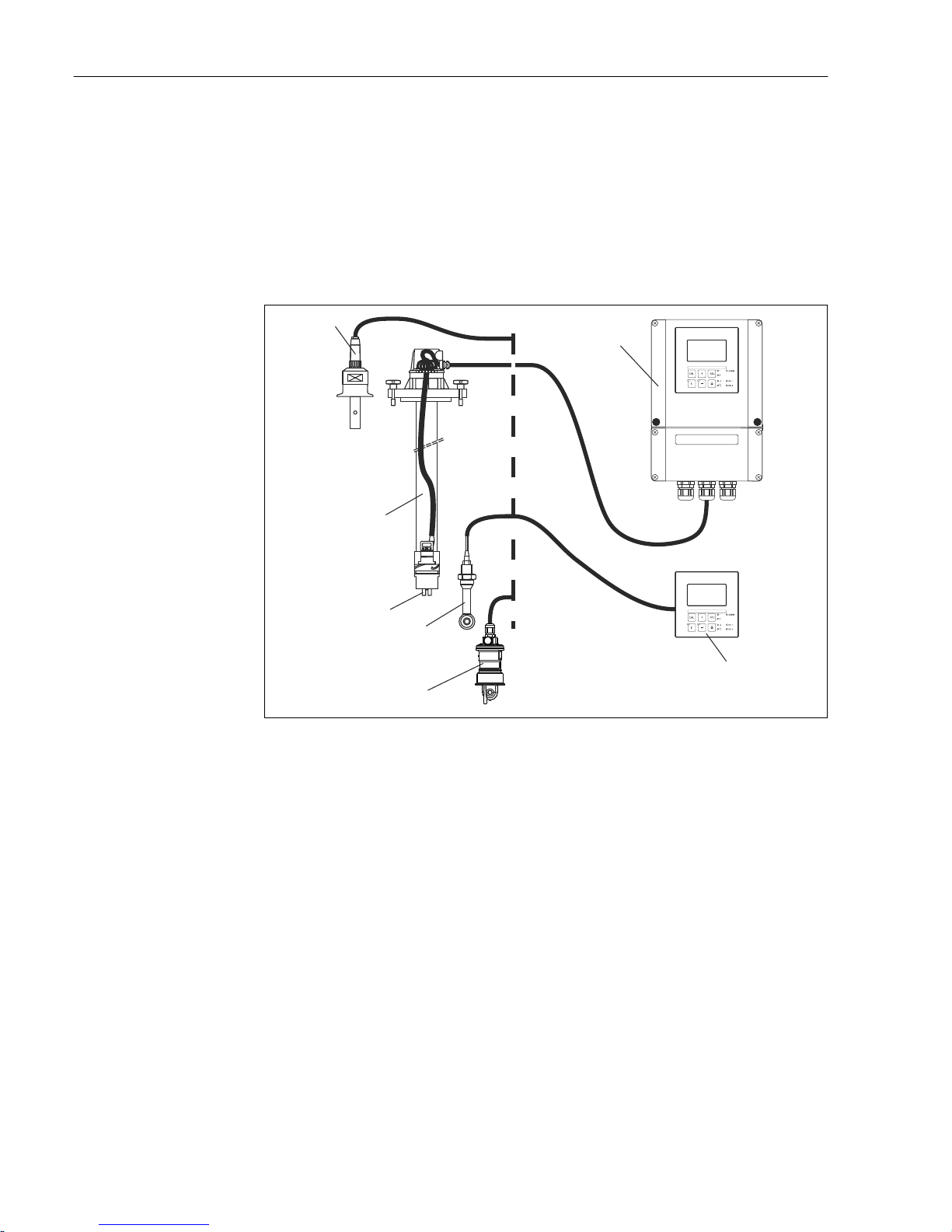
A complete measuring system comprises:
• Transmitter Liquisys M CLM223 or CLM253
• sensor with or without an integrated temperature sensor
• If necessary, Measuring cable: CYK71 or CPK9 (conductive) or CLK6 (inductive)
Optionally:
• Eintaucharmatur, z.B. CLA111
• Extension cable, junction box VBM
• Weather protection cover CYY101 for field housing
ENDRESS+HAUSER
LIQUISYS S
ENDRESS+HAUSER
LIQUISYS S
1
2
3
4
5
6
7
A0024642
1 Complete measuring systems
1 Conductive sensor CLS15
2 Liquisys M CLM253
3 Liquisys M CLM223
4 Inductive sensor CLS54
5 Inductive sensor CLS50
6 Conductive sensor CLS21
7 Immersion assembly CLA111
Page 13
Liquisys M CLM223/253 Installation
Endress+Hauser 13
4.2 Installation conditions
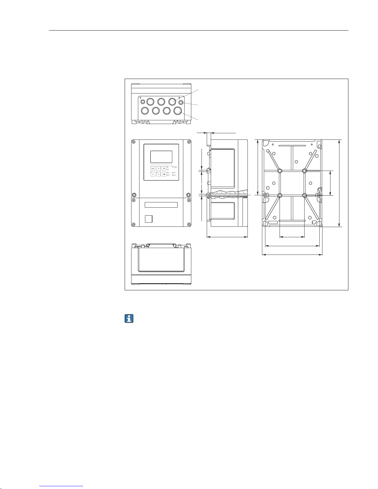
4.2.1 Field device
Pg 7
Pg 16
M 5
11 (0.43)
Ø 6 (0.24)
115 (4.53)
157 (6.18)
247 (9.72)
70 (2.76)
70 (2.76)
154 (6.06)
170 (6.69)
Pg 13.5
A0024637
2 Field device, dimensions in mm (inch)
There is a hole in the perforation for the cable entry (connection of supply voltage). It
serves as a pressure balance during air shipment. Make sure no moisture penetrates
the inside of the housing before the cable installation. The housing is completely airtight after cable installation.
Page 14
Installation Liquisys M CLM223/253
14 Endress+Hauser
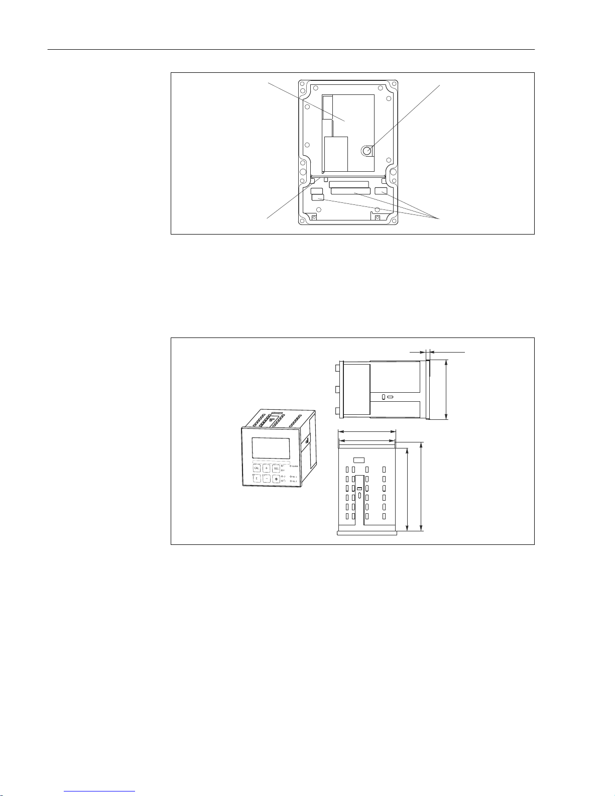
1
2
3
4
A0024640
3 View into the field housing
1 Removable electronics box
2 Terminals
3 Partition plate
4 Fuse
4.2.2 Panel-mounted device
90 (3.54)
139 (5.47)
96 (3.78)
6 (0.24)
92 (3.62)
149.5 (5.89)
A0024641
4 Panel-mounted device, dimensions in mm (inch)
Page 15
Liquisys M CLM223/253 Installation
Endress+Hauser 15
4.3 Installation instructions
4.3.1 Field device
There are several ways of securing the field housing:
• Wall mounting with fixing screws
• Post mounting to cylindrical pipes
• Post mounting to a square securing mast
NOTICE
Effect of climatic conditions (rain, snow, direct sunlight etc.)
Impaired operation to complete transmitter failure
‣
When installing outside, always use the weather protection cover (accessory).
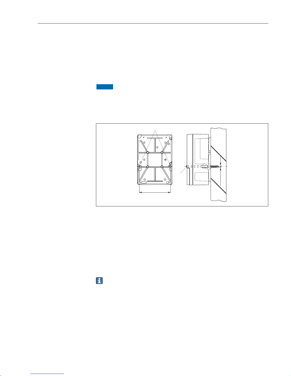
Transmitter wall mounting
1
2
154 (6.06)
Ø 6 (0.24)
A0024638
5 Field device wall mounting
1 Fixing bore holes
2 Plastic caps
Proceed as follows to mount the transmitter on the wall:
• Create the bore holes as shown in → 5.
• Drive two fixing screws through the fixing bore holes (1) from the front.
• Mount the transmitter on the wall as shown.
• Cover the bores with plastic caps (2).
Transmitter post mounting
You require a post mounting kit to secure the field device to horizontal and vertical
posts or pipes (max. Ø 60 mm (2.36")). This can be acquired as an accessory (see the
"Accessories" section).
Page 16
Installation Liquisys M CLM223/253
16 Endress+Hauser
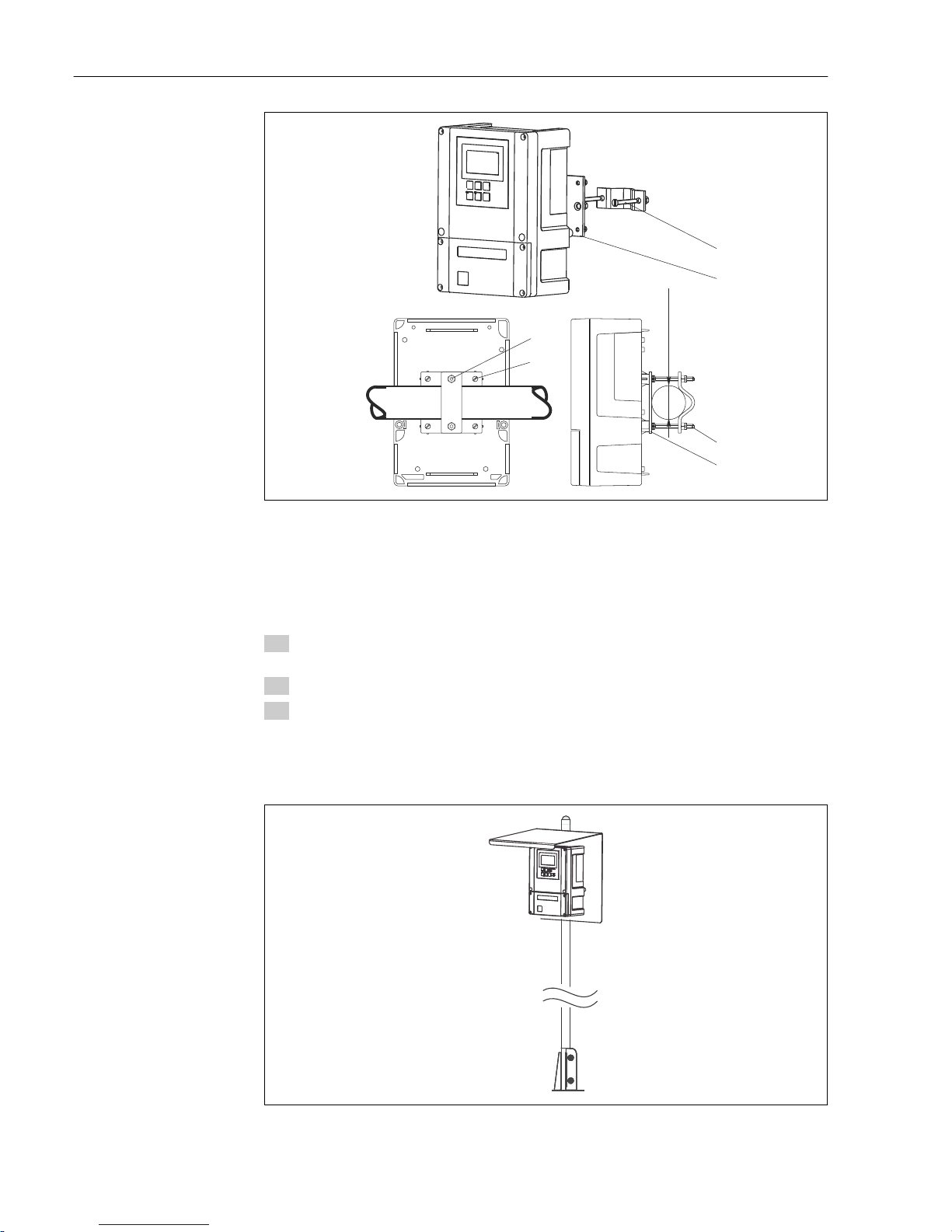
1
2
3
1
1
3
Ø max. 60 (2.36)
A0024635
6 Field device on horizontal or vertical pipes
1 Securing screws
2 Fixing screws
3 Securing plate
Proceed as follows to mount the transmitter on a post:
1. Guide the two securing screws (1) of the mounting kit through the openings on the
securing plate (3).
2. Screw the securing plate onto the transmitter using the four fixing screws (2).
3. Secure the bracket with the field device on the post or pipe using the clip.
You can also secure the field device to the Flexdip CYH112 bracket in conjunction with the
weather protection cover. These can be acquired as accessories, see the "Accessories"
section.
A0027433
7 Field device on Flexdip CYH112 bracket with weather protection cover
Page 17
Liquisys M CLM223/253 Installation
Endress+Hauser 17
4.3.2 Panel-mounted device
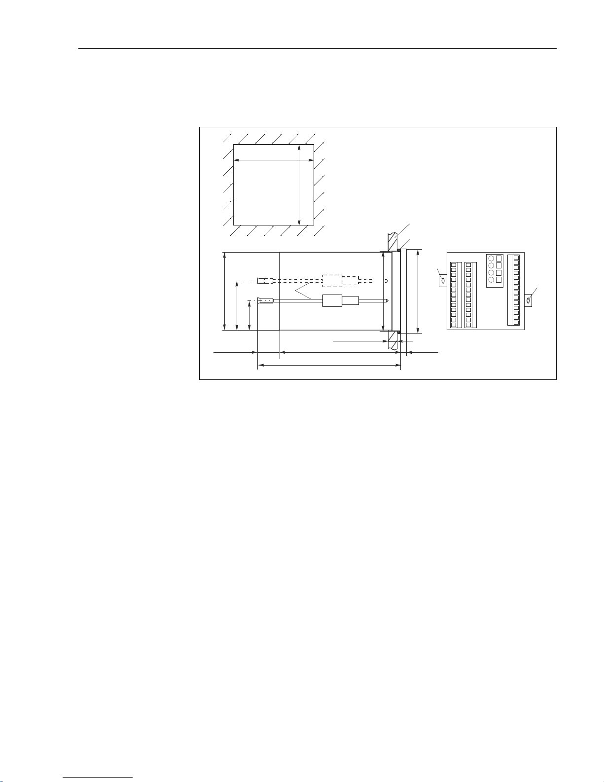
The panel-mounted device is secured with the tensioning screws supplied → 8
The necessary installation depth is approx. 165 mm (6.50").
1
2
3
3
3
92 (3.62
+0.5 +0.02
)
92 (3.62
+0.5 +0.02
)
90 (3.54)
57 (2.24)
33 (1.30)
~ 25 (0.98)
139 (5.47)
max. 45 (1.77)
6 (0.24)
96 (3.78)
~ 165 (6.50)*
92 (3.62)
A0024639
8 Dimensions in mm (inch)
1 Mounting plate
2 Seal
3 Tensioning screws
* Necessary installation depth
4.4 Post-installation check
• After installation, check the transmitter for damage.
• Check whether the transmitter is protected against moisture and direct sunlight (e.g. by
the weather protection cover).
Page 18

Electrical connection Liquisys M CLM223/253
18 Endress+Hauser
5 Electrical connection
L
WARNING
Device is live
Incorrect connection may result in injury or death.
‣
The electrical connection may be performed only by an electrical technician.
‣
The electrical technician must have read and understood these Operating Instructions
and must follow the instructions contained therein.
‣
Prior to commencing connection work, ensure that no voltage is present on any cable.
5.1 Wiring
L
WARNING
Risk of electric shock!
‣
At the supply point, the power supply must be isolated from dangerous live cables by
double or reinforced insulation in the case of devices with a 24 V power supply.
NOTICE
The device does not have a power switch
‣
The customer must provide a protected circuit breaker in the vicinity of the device.
‣
The circuit breaker must be a switch or power switch, and you must label it as the
circuit breaker for the device.
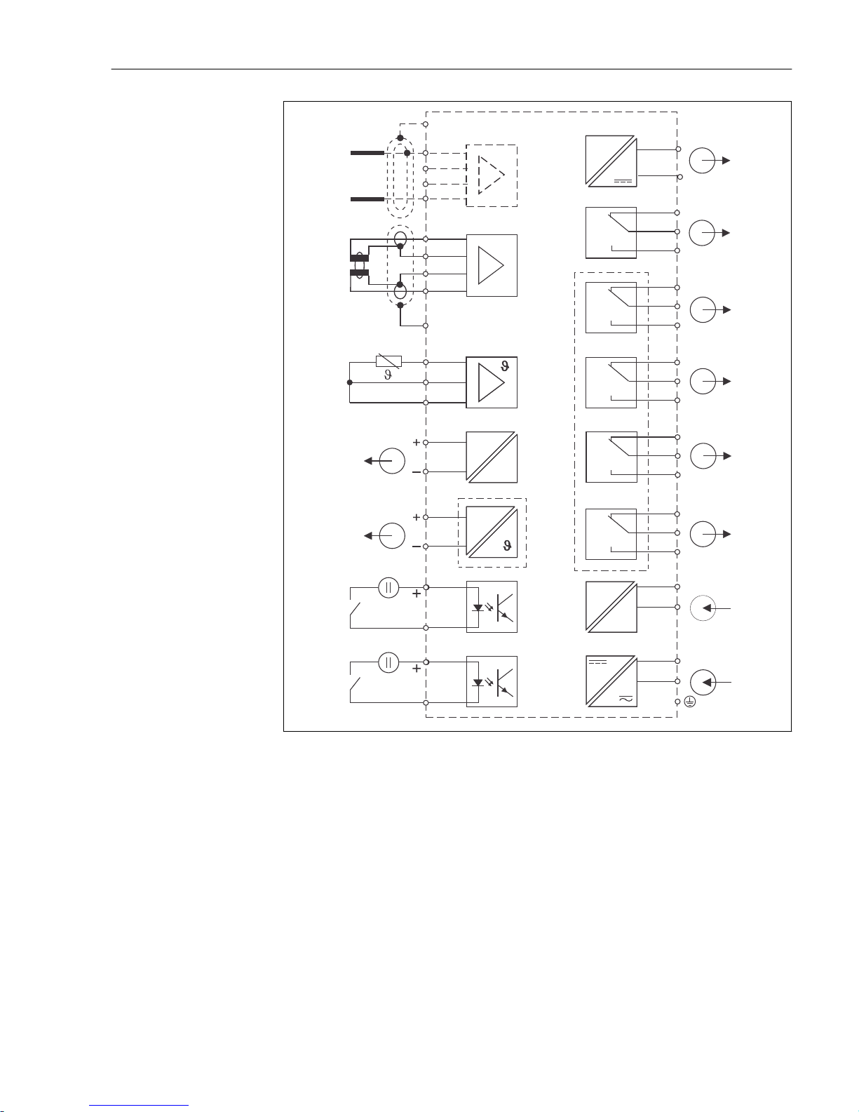
5.1.1 Wiring diagram
The wiring diagram shows the connections of a device equipped with all the options. The
connection of the sensors to the various measuring cables is explained in more detail in
the "Measuring cables and sensor connection" section.
Page 19
Liquisys M CLM223/253 Electrical connection
Endress+Hauser 19
11
12
13
47
48
49
57
58
59
15 V
10-50 V
81
82
10-50 V
93
94
41
42
43
Lf
mA
31
32
mA
33
34
51
52
53
54
55
56
S
84
83
15
16
84
PE
83
L+
L–N
L1
~ =
PE
23 +
24 -
mA
15
16
85+
86
_
A
B
C
D
E
F
G
H
I
J
K
L
M
N
O
A0008920
9 Electrical connection of the transmitter
A Sensor (conductive) I Alarm (current-free contact position)
B Sensor (inductive) J Relay 1 (current-free contact position)
C Temperature sensor K Relay 2 (current-free contact position)
D Signal output 1, conductivity L Relay 3 (current-free contact position)
E Signal output 2, user-definable variable M Relay 4 (current-free contact position)
F Binary input 1 (hold) N Current input 4 to 20 mA
G Binary input 2 (Chemoclean) O Power connection
H Auxiliary voltage output
Page 20
Electrical connection Liquisys M CLM223/253
20 Endress+Hauser
Please note the following:
• The device is approved for protection class II and is generally operated without a
protective ground connection.
• To guarantee measuring stability and functional safety, you must connect the outer
shield of the sensor cable:
– Inductive sensors: terminal "S"
– Conductive sensors: PE distributor rail
This is on the cover frame in the case of panel-mounted devices, and in the connection
compartment in the case of field devices. Ground this PE distributor rail or the ground
terminal directly on site wherever possible.
• Circuits "E" and "H" are not galvanically isolated from each other.
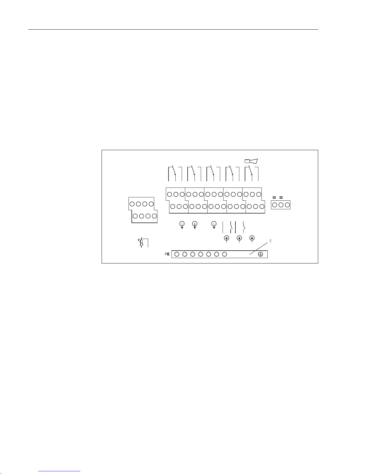
Field device connection
Guide the measuring cables through the PG glands into the housing. Connect the
measuring cables in accordance with the terminal assignment.
42
+++++ -----
434154 55 56
NC
121311
31
83 84 15
32163433SNC 938685 94 81 82 NC
51 52 53 57 58 59 47 48 49
Lf
Temp.
(opt. )
+15V
10mA
WH
YE
GN
REL 4SENSO R REL 3 REL 2 REL 1
13109 5-4F
2
1
11 12
13
NC
Mains
Hilfs energ ie
L1+N
-
(AC)
(DC)
Conta cts:
max. 2A
AC: 250 V/500 VA
DC: 30V /60W
+ -
23 24
4..20 mA
PE
1
Binär/
Binary
Binär/
Binary
A0008915
10 Field device connection compartment sticker
1 PE distributor rail for CD/CS device version (conductive sensors)
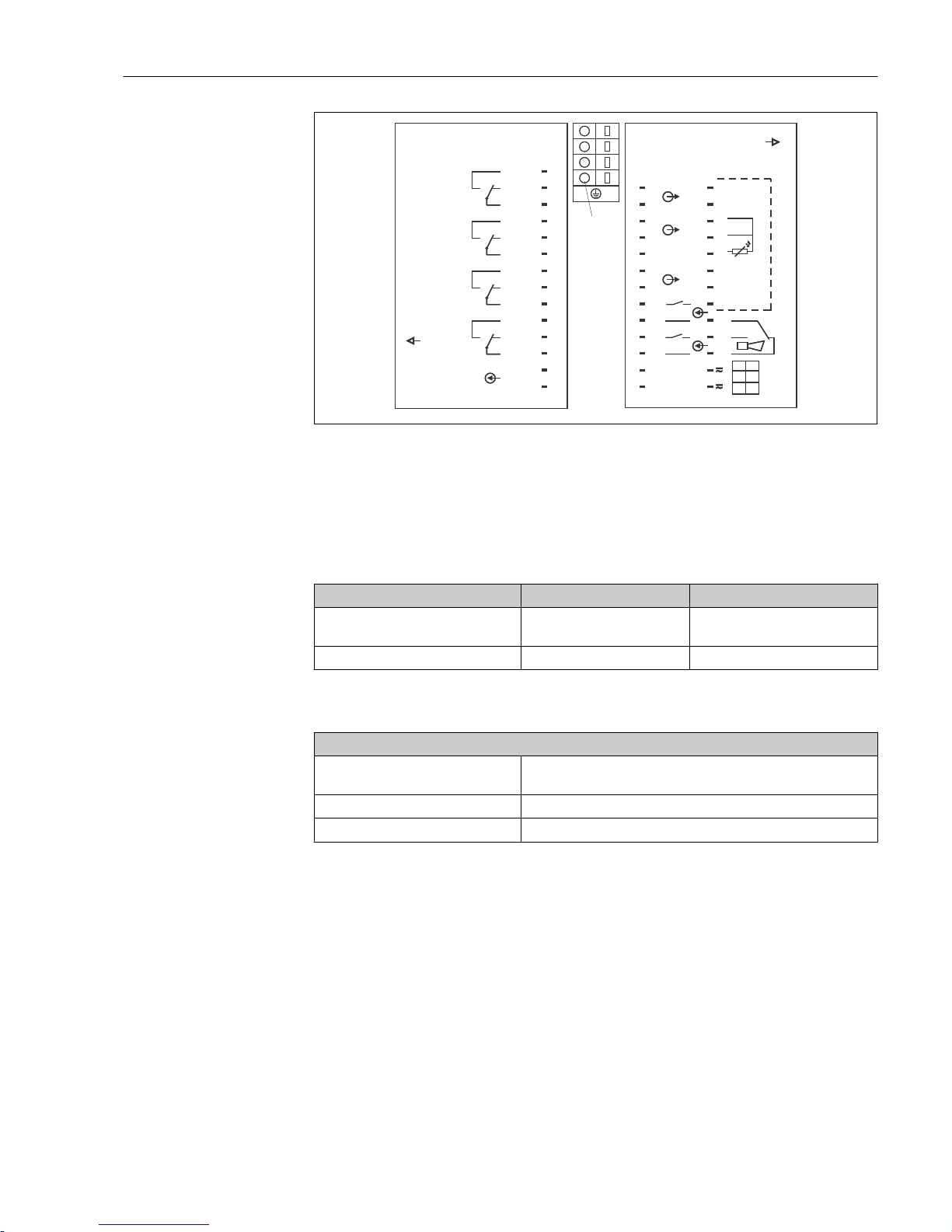
Panel-mounted device connection
Page 21
Liquisys M CLM223/253 Electrical connection
Endress+Hauser 21
31 +
Senso r
32 -
33 +
34 -
85 +
86 -
93 +
94 - 42
81 + 43
82 - 41
Temp.
(opt. )
+15V
10mA
2
1
NC
NC
NC
13108 1-4E
S
13
12
YE
GN
Mains
Contac ts: max. 2A, AC:2 50V/500VA, DC:3 0V/60W
L1 +
AC DC
N -
REL1
REL2
REL3
REL4
4..20 mA
24
23
49
COM
COM
COM
COM
-
+
59
54
55
56
52
51
53
58
57
48
47
13108 4-4C
15
11
WH
L1 +
AC DC
N -
1
Lf
84
16
83
Binary
Binary
A0008912
11 Panel-mounted device connection sticker
1 Ground terminal
5.1.2 Measuring cables and sensor connection
You require shielded special measuring cables to connect conductivity sensors to the
transmitter. The following multi-core, pre-terminated cable types can be used:
Sensor type Cable Extension
Two-electrode sensor with or without
temperature sensor Pt 100
CYK71
CPK9* (for CLS16)
VBM box + CYK71 cable
Inductive sensor CLS50, CLS52 Fixed cable on sensor VBM box + CLK6 cable
* High-temperature version without PML
Maximum cable length
Conductive measurement of
conductivity
Max. 100 m (328 ft) with CYK71
Resistance measurement Max 15 m (49.2 ft) with CYK71
Inductive measurement of conductivity Max. 55 m ( 180 ft) with CLK5 (incl. sensor cable)
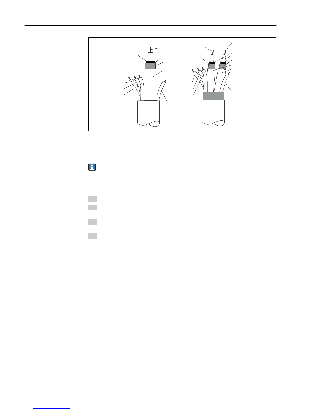
Structure and termination of the measuring cables
Page 22
Electrical connection Liquisys M CLM223/253
22 Endress+Hauser
83
84
11
12
13
CYK71
CLK6
15
16
83
84
11
12
13
green
green
white
white
yellow
yellow
brown (nc)
brown (nc)
black
white
red
semiconductor
screen
semiconductor
screen
screen
screen
screen
A0008938-EN
12 Structure of the special measuring cables
A Semi-conductor layer
sc Shield
For further information on the cables and junction boxes, please refer to the
"Accessories" section.
Field device measuring cable connection
Proceed as follows to connect a conductivity sensor to the field device:
1. Open the housing cover to access the terminal block in the connection compartment.
2. Break through the perforation for a cable gland, mount a cable gland and guide the
cable through this gland.
3. Connect the cable in accordance with the terminal assignment (see connection
compartment sticker).
4. Tighten the cable gland.
Panel-mounted device measuring cable connection
Page 23
Liquisys M CLM223/253 Electrical connection
Endress+Hauser 23
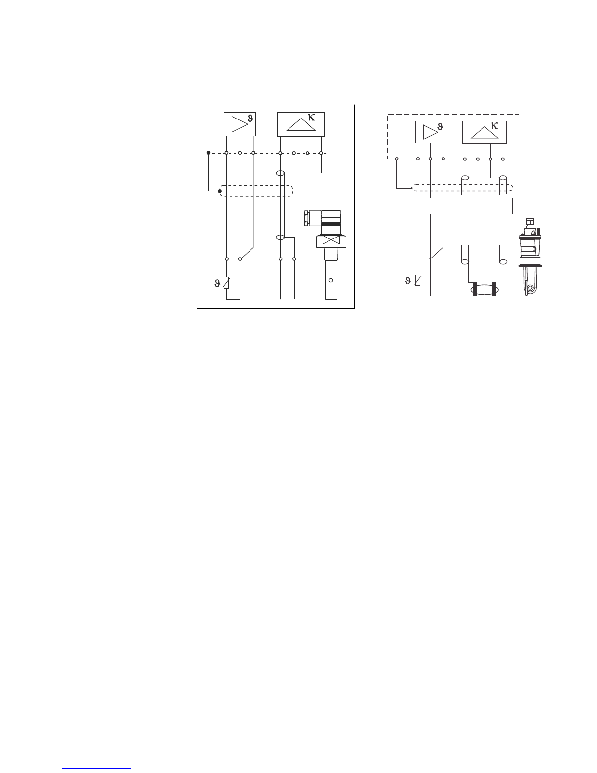
To connect a conductivity sensor, connect the measuring cable in accordance with the
terminal assignment to the terminals on the rear of the device (see connection sticker).
GN WH YE
GN WH YE
BK
BK
CYK71/CPK9
83 16 15 84
23 1
11 12 13
PE
A0008919
13 Connection of conductive sensors
83
11
S
12
161584
CLK6
13
GN
WH
YE
RD
WH
BU
RD
RD
BU
A0008918
14 Connection of inductive sensors
Page 24
Electrical connection Liquisys M CLM223/253
24 Endress+Hauser
5.2 Alarm contact
41
42
43
41
42
43
A
B
A0006415
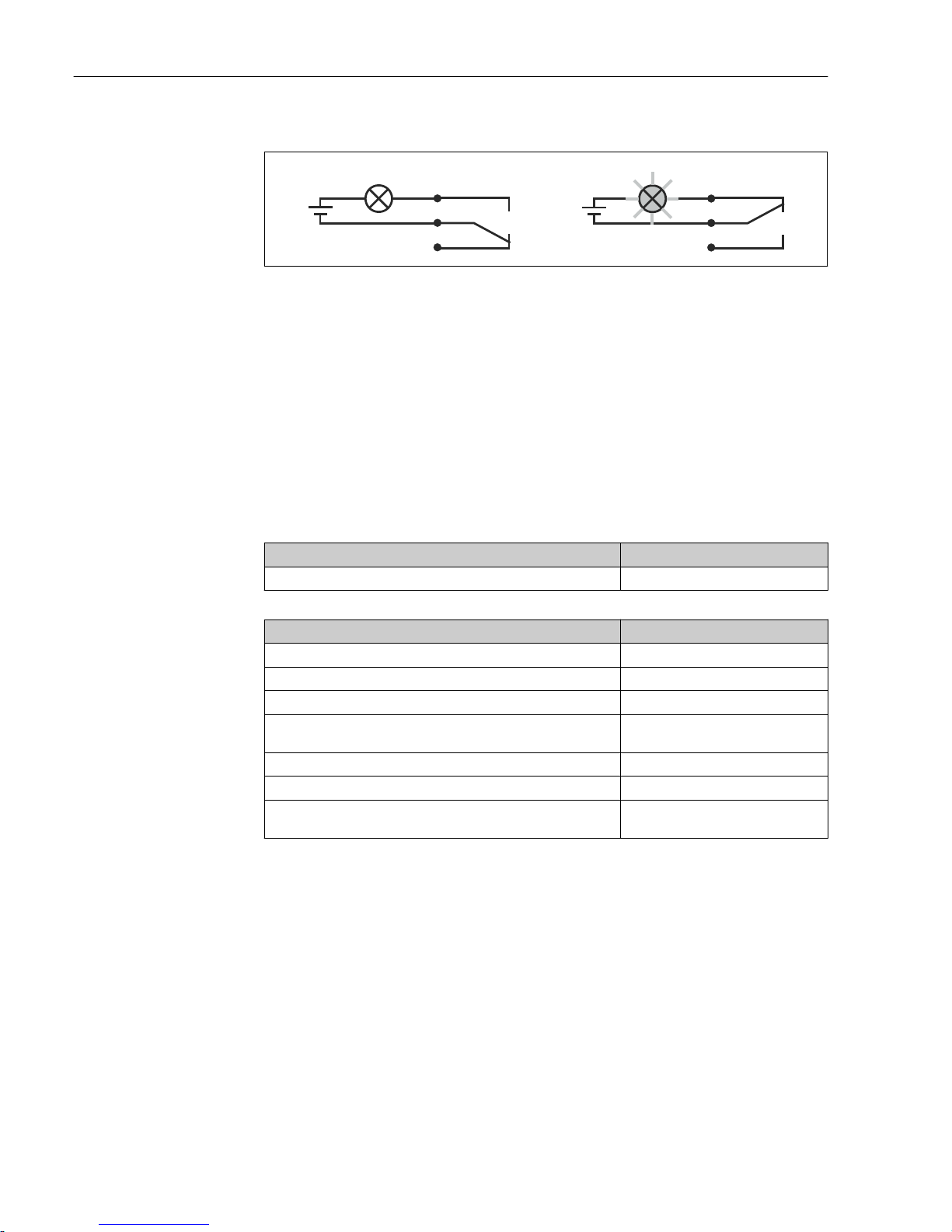
15 Recommended fail-safe switching for the alarm contact
A Normal operating status
B Alarm condition
Normal operating status Alarm condition
Device in operation and no error message
present (alarm LED off):
• Relay energized
• Contact 42/43 closed
Error message present (alarm LED red) or device
defective or de-energized (alarm LED off):
• Relay de-energized
• Contact 41/42 closed
5.3 Post-connection check
Carry out the following checks once you have made the electrical connection:
Device state and specifications Notes
Are the devices and cables free from damage on the outside? Visual inspection
Electrical connection Notes
Are the mounted cables strain relieved?
Are the connected cables provided with strain relief?
Is the cable run correct, without loops and cross-overs?
Are the power cable and signal cables connected correctly and in
accordance with the wiring diagram?
Are all the screw terminals tightened?
Are all the cable entries fitted, tightened and leak-proof?
Are the PE distributor blocks grounded (if present)? Grounding is carried out at the point of
installation.
Page 25
Liquisys M CLM223/253 Operation options
Endress+Hauser 25
6 Operation options
6.1 Quick operation guide
You have the following ways of operating the transmitter:
• On site via the key field
• Via the HART interface (optional, with corresponding order version) with:
– HART handheld terminal
– PC with HART modem and the Fieldcare software package
• Via PROFIBUS PA/DP (optional, with corresponding order version) by PC with a
corresponding interface and the Fieldcare software package or via a programmable logic
controller (PLC).
For operation via HART or PROFIBUS PA/DP, please read the relevant sections in the
additional Operating Instructions:
• PROFIBUS PA/DP, field communication for Liquisys M CXM223/253,
BA00209C/07/EN
• HART, field communication for Liquisys M CXM223/253, BA00208C/07/EN
The following section only explains operation via the keys.
6.2 Display and operating elements
6.2.1 Display
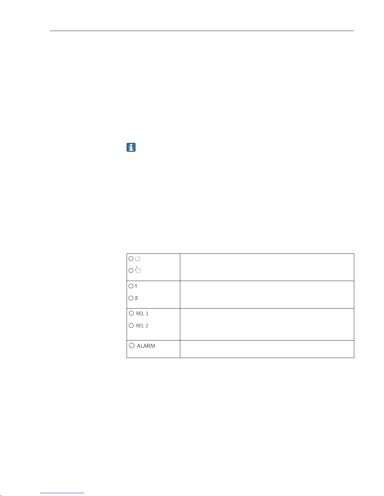
LED displays
A0027220
Indicates the current operating mode, "Auto" (green LED) or
"Manual" (yellow LED)
A0027222
Indicates the activated relay in the "Manual" mode (red LED)
The status of relays 3 and 4 is indicated on the LC display.
A0027221
Indicates the working status of relay 1 and 2
LED green: measured value within the permitted limit, relay
inactive
LED red: measured value outside the permitted limit, relay active
A0027218
Alarm display, e.g. in event of continuous limit value overshoot,
temperature sensor failure or system error (see error list)
Page 26
Operation options Liquisys M CLM223/253
26 Endress+Hauser
LC display
15
mS/cm
R232
1
2 3
4
5
6
7
8
9
10
11
12
13
12
Setpoint
A0008922-EN
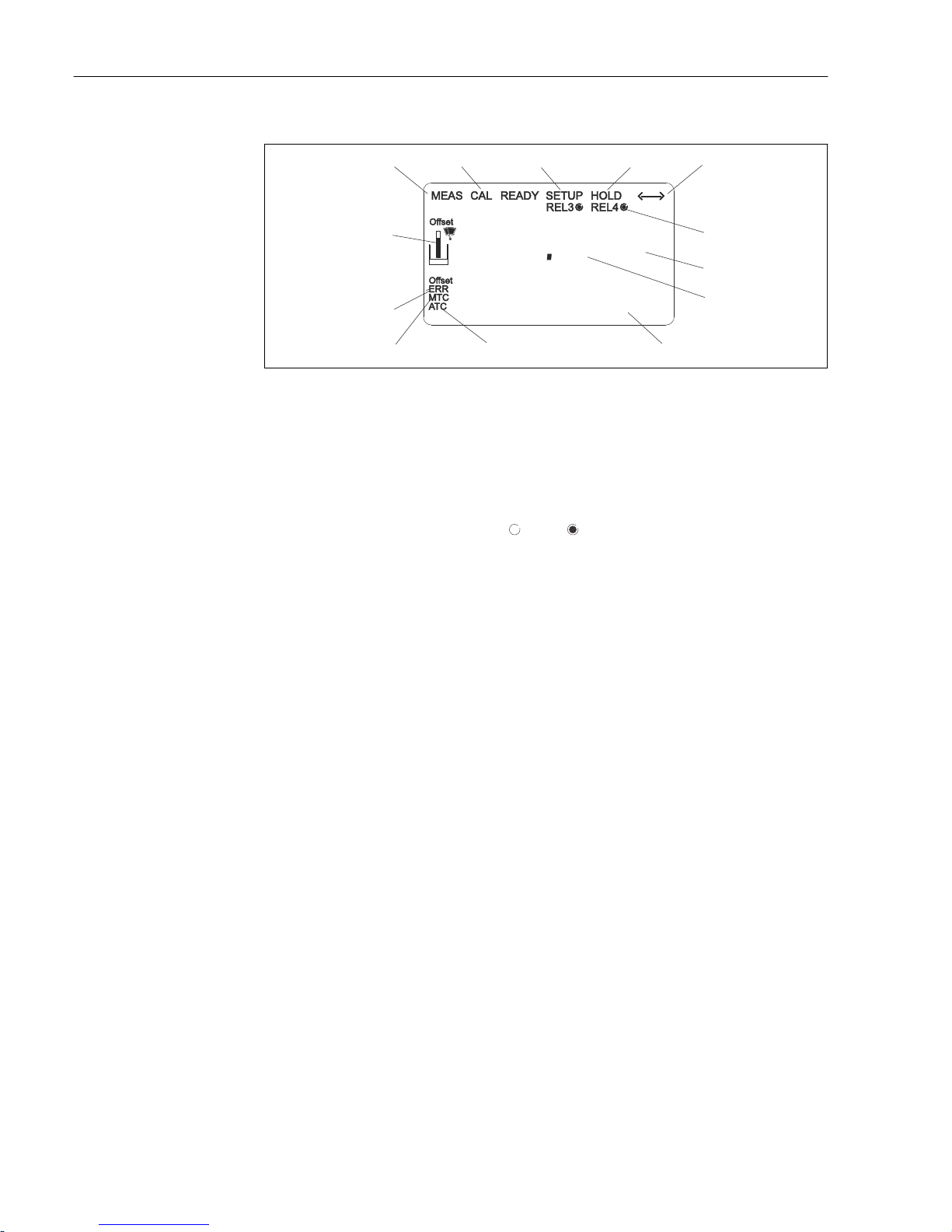
16 Transmitter LC display
1 Indicator for measuring mode (normal operation)
2 Indicator for calibration mode
3 Indicator for setup mode (configuration)
4 Indicator for "Hold" mode (current outputs remain at last current state)
5 Indicator for receipt of a message on devices with communication
6 Indicator of working status of relays 3/4: inactive, active
7 Function code
8 In measuring mode: measured variable - in setup mode: configured variable
9 In measuring mode: secondary measured value - in setup/calibr. mode: e.g. set value
10 Indicator for autom. Temperature compensation
11 Indicator for man. Temperature compensation
12 "Error": error display
13 Sensor symbol (see the "Calibration" section)
Page 27
Liquisys M CLM223/253 Operation options
Endress+Hauser 27
6.2.2 Operating elements
The display shows the current measured value and the temperature simultaneously, which
means you have an overview of the most important process data at once. Help text in the
configuration menu helps users configure the device parameters.
1
7
6
4
5
3
2
A0024632-EN
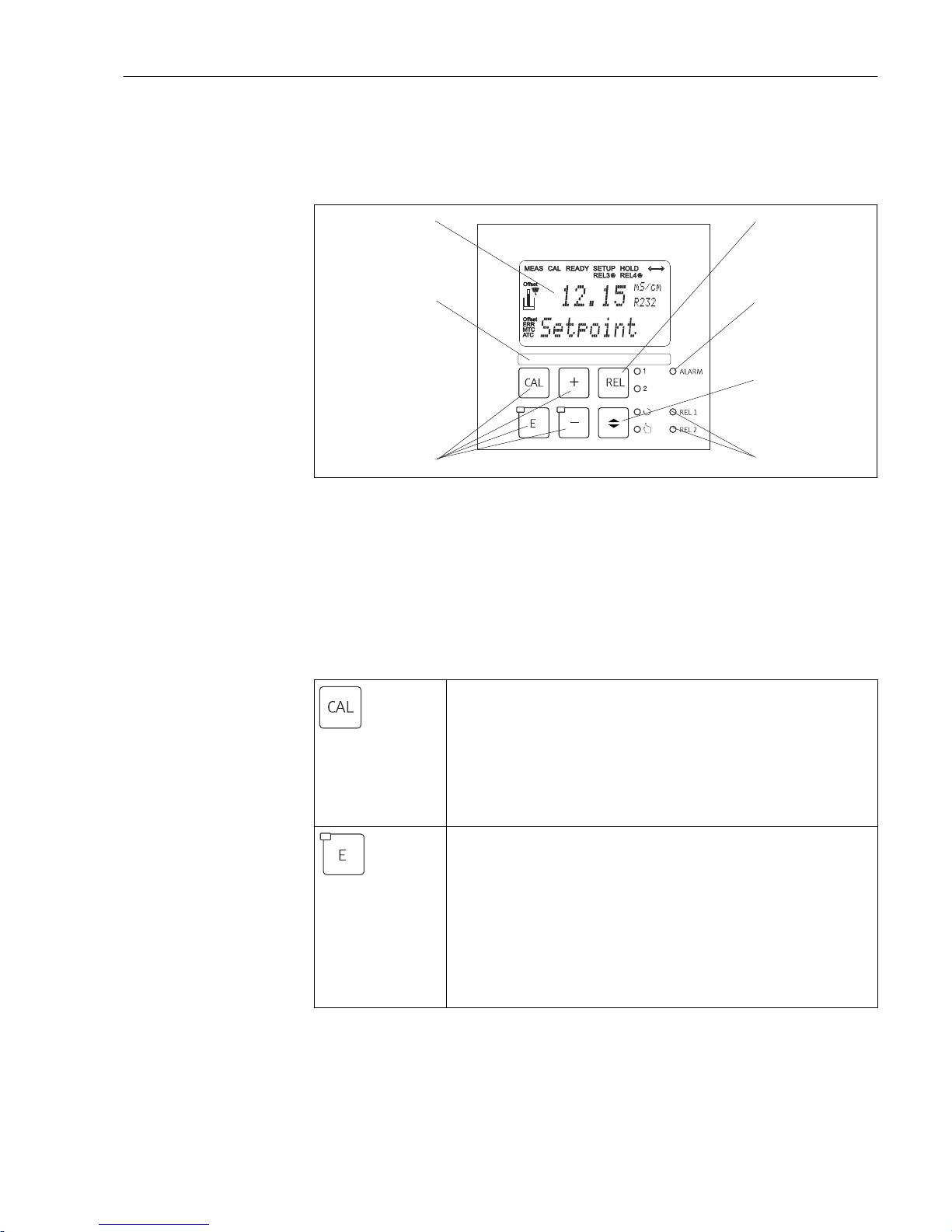
17 Operating elements
1 LC display for displaying the measured values and configuration data
2 Key to switch relays in manual mode and to display the active contact
3 LED for alarm function
4 Changeover switch for automatic/manual mode
5 LEDs for limit contactor relay (switch status)
6 Main operating keys for calibration and device configuration
7 Field for user-defined information
6.2.3 Key functions
A0027235
CAL key
When you press the CAL key, the device first prompts you for the
calibration access code:
• Code 22 for calibration
• Code 0 or any other code for reading the last calibration data
Use the CAL key to accept the calibration data or to switch from
field to field within the calibration menu.
A0027236
ENTER key
When you press the ENTER key, the device first prompts you for the
setup mode access code:
• Code 22 for setup and configuration
• Code 0 or any other code for reading all the configuration data.
The ENTER key has several functions:
• Calls up the Setup menu from the measuring mode
• Saves (confirms) data entered in the setup mode
• Moves on within function groups
Page 28
Operation options Liquisys M CLM223/253
28 Endress+Hauser
A0027240
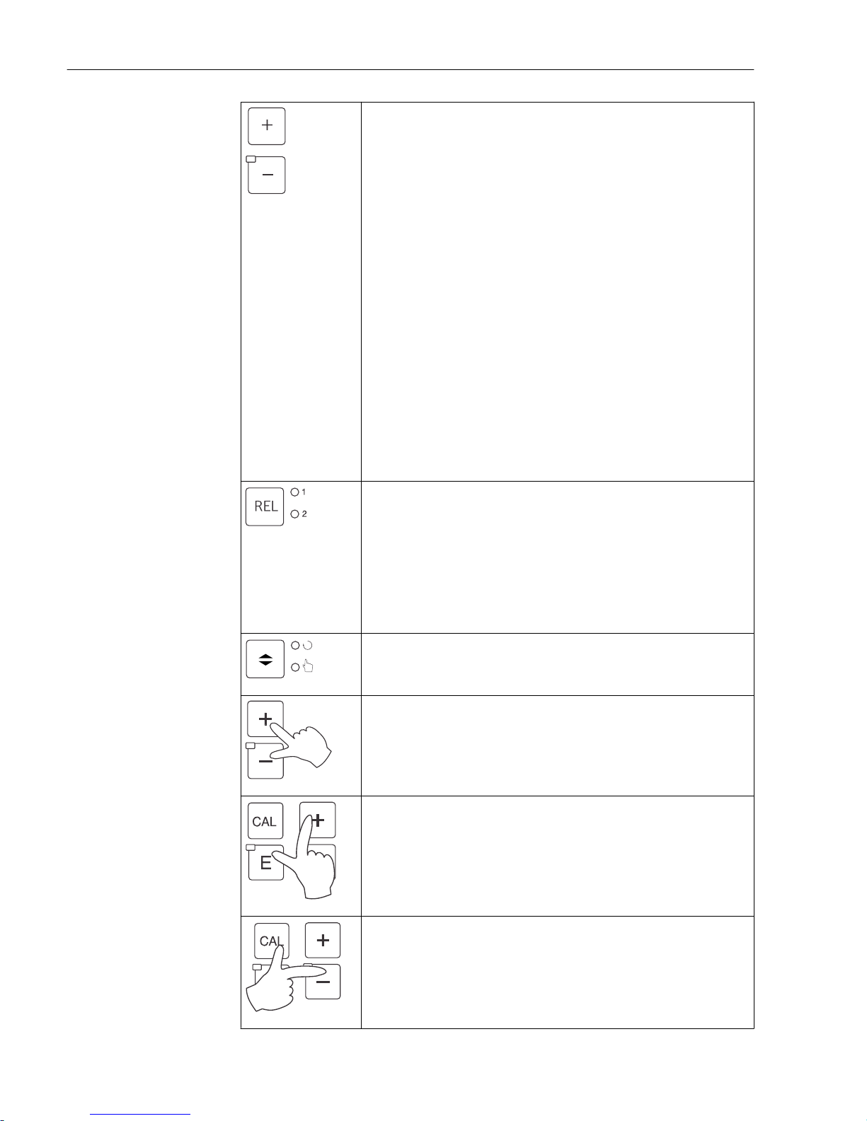
PLUS key and MINUS key
In the Setup mode, the PLUS and MINUS keys have the following
functions:
• Selection of function groups.
Press the MINUS key to select the function groups in the order
given in the "System configuration" section.
• Configuration of parameters and numerical values
• Operation of the relays in manual mode
In the measuring mode, the following sequence of functions is
accessed by repeatedly pressing the PLUS key:
• Temperature displayed in °F
• Temperature is hidden
• Current input signal in %
• Current input signal in mA
• Uncompensated conductivity value is displayed
• Return to basic settings
In the measuring mode, the following sequence of information is
displayed by repeatedly pressing the MINUS key:
• The current errors are displayed consecutively (max. 10).
• Once all the errors have been displayed, the standard
measurement display appears. In the function group F, an alarm
can be defined separately for each error code.
A0027241
REL key
In the manual mode, you can use the REL key to switch between the
relay and the manual start of cleaning.
In automatic mode, you can use the REL key to read out the switchon points (for limit contactor) or set points (for PID controller)
assigned to the relay in question.
Press the PLUS key to jump to the settings of the next relay. Use the
REL key to get back to the display mode (automatic return after
30 s).
A0027234
AUTO key
Use the AUTO key to switch between automatic mode and manual
mode.
A0027237
Escape function
If you press the PLUS and MINUS key simultaneously, you return to
the main menu, or are taken to the end of calibration if calibrating.
If you press the PLUS and MINUS key again, you return to the
measuring mode.
A0027238
Locking the keyboard
Press the PLUS and ENTER key simultaneously for at least 3 s to
lock the keyboard against any unauthorized data entry. All the
settings can continue to be read.
The code prompt displays the code 9999.
A0027239
Unlocking the keyboard
Press the CAL and MINUS key simultaneously for at least 3 s to
unlock the keyboard.
The code prompt displays the code 0.
Page 29
Liquisys M CLM223/253 Operation options
Endress+Hauser 29
6.3 Local operation
6.3.1 Automatic/manual mode
The transmitter normally operates in automatic mode. Here, the relays are triggered by
the transmitter. In the manual mode, you can trigger the relays manually using the REL
key or start the cleaning function.
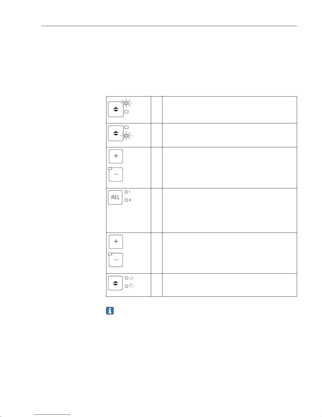
How to change the operating mode:
A0027242
1. The transmitter is in automatic mode. The top LED (green)
next to the AUTO key is lit.
A0027243
2. Press the AUTOMATIC key.
A0027240
3. To enable the manual mode, enter the code 22 via the PLUS
and MINUS keys and press ENTER to confirm.
The lower LED (manual mode) is lit.
A0027241
4. Select the relay or the function.
You can use the REL key to switch between the relays. The
relay selected and the switch status (ON/OFF) is displayed on
the second line of the display.
In the manual mode, the measured value is displayed
continuously (e.g. for measured value monitoring for dosing
functions).
A0027240
5. Switch the relay. The relay is switched on with PLUS and
switched off with MINUS.
The relay remains in this switched state until it is switched
again.
A0027234
6. Press the AUTOMATIC key to return to the measuring mode,
i.e. to the automatic mode.
All the relays are triggered again by the transmitter.
• The operating mode remains in effect even after a power failure. The relays assume
the quiescent state, however.
• The manual mode has priority over all other automatic functions.
• Hardware locking is not possible in the manual mode.
• The manual settings are kept until they are actively reset.
• Error code E102 is signaled during manual operation.
Page 30
Operation options Liquisys M CLM223/253
30 Endress+Hauser
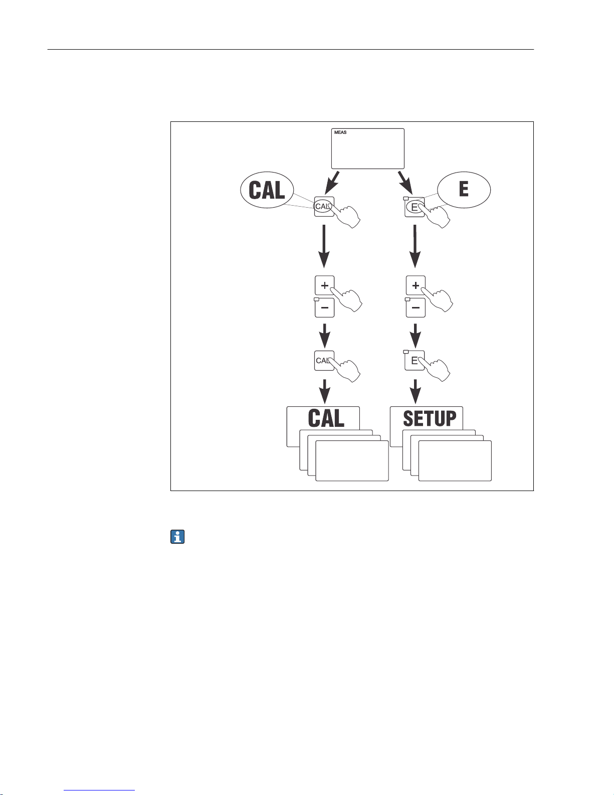
6.3.2 Operating concept
Operating modes
Code
Measuring mode:
standard mode of
operation, displaying
current measured values
Setup mode
access to all
configuration
settings
Calibration mode:
execution of
calibration routine
The function groups
are selected with the
PLUS or MINUS key.
A0027244-EN
18 Description of the possible operating modes
If no key is pressed in the setup mode for approx. 15 min, the device automatically
returns to the measuring mode. Any active hold (hold during setup) is canceled.
Access codes
All device access codes are fixed and cannot be altered. When the device requests the
access code, it distinguishes between different codes.
• CAL key + code 22: access to Calibration and Offset menu
• ENTER key + code 22: access to the menus for the parameters which make
configuration and user-specific settings possible
• PLUS + ENTER keys simultaneously (min. 3 s): lock the keyboard
• CAL + MINUS keys simultaneously (min. 3 s): unlock the keyboard
• CAL or ENTER key + any code: access to read mode, i.e. all the settings can be read but
not modified.
The device continues measuring in the read mode. It does not shift to the "Hold" status.
The current output and the controllers remain active.
Page 31
Liquisys M CLM223/253 Operation options
Endress+Hauser 31
Menu structure
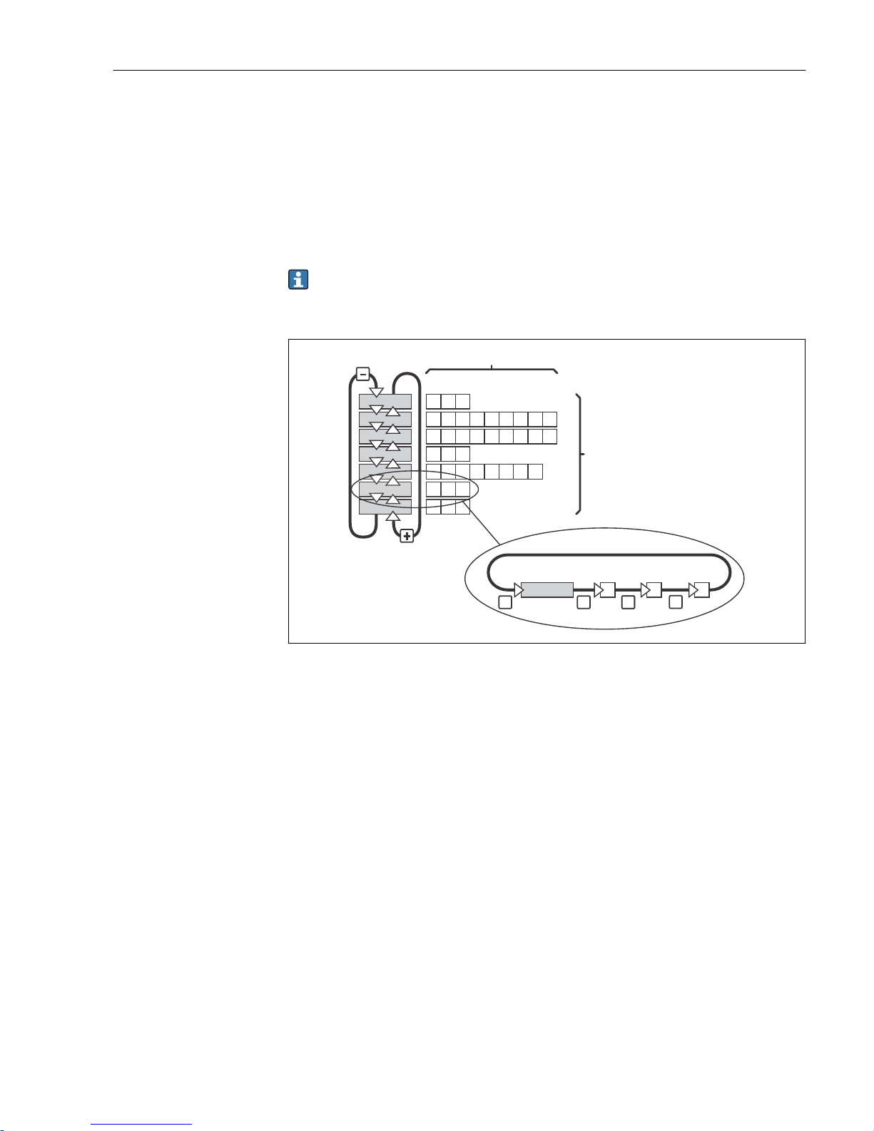
The configuration and calibration functions are arranged in function groups.
• In the setup mode, select a function group with the PLUS and MINUS keys.
• In the function group itself, switch from function to function with the ENTER key.
• Within the function, select the desired option with the PLUS and MINUS keys or edit the
settings with these keys. Then confirm with the ENTER key and continue.
• Press the PLUS and MINUS keys simultaneously (Escape function) to exit programming
(return to the main menu).
• Press the PLUS and MINUS keys simultaneously again to switch to the measuring mode.
If a modified setting is not confirmed by pressing ENTER, the old setting is retained.
An overview of the menu structure is provided in the Appendix to these Operating
Instructions.
E E
-
1
2
3
E
E
E
E
A0027245
19 Menu structure
1 Functions (selection of parameters, entry of numbers)
2 Function groups, scroll backwards and forwards with the PLUS and MINUS keys
3 Switch from function to function with the ENTER key
Hold function: "freeze" the outputs
In both the setup mode and during calibration, the current output can be "frozen" (factory
setting), i.e. it constantly retains its current status. "HOLD" appears on the display. If the
controller actuating variable (steady control 4 to 20 mA) is output via current output 2, it
is set to 0/4 mA during a hold.
• Hold settings can be found in the "Service" function group.
• During a hold, all contacts assume a quiescent state.
• An active hold has priority over all other automatic functions.
• With every hold, the I-component of the controller is set to "0".
• Any alarm delay is reset to "0".
• This function can also be activated externally via the hold input (see Wiring diagram;
binary input 1).
• A manual hold (field S3) remains active even after a power failure.
Page 32
Commissioning Liquisys M CLM223/253
32 Endress+Hauser
7 Commissioning
7.1 Function check
L
WARNING
Incorrect connection, incorrect supply voltage
Safety risks for staff and device malfunctions
‣
Check that all connections have been established correctly in accordance with the
wiring diagram.
‣
Ensure that the supply voltage matches the voltage indicated on the nameplate.
7.2 Switching on
Familiarize yourself with the operation of the transmitter before it is first switched on. In
particular please read the "Basic safety instructions" and "Operation options" sections. After
power-up, the device performs a self-test and then goes to the measuring mode.
Now calibrate the sensor in accordance with the instructions in the "Calibration" section.
During initial commissioning, the sensor must be calibrated so that the measuring
system can return precise measurement data.
Then perform the first configuration in accordance with the instructions in the "Quick
setup" section. The values set by the user are kept even in the event of a power failure.
The following function groups are available in the transmitter (the groups that are only
available in the Plus Package are marked accordingly in the functional description):
Setup mode
• SETUP 1 (A)
• SETUP 2 (B)
• CURRENT INPUT (Z)
• CURRENT OUTPUT (O)
• ALARM (F)
• CHECK (P)
• RELAY (R)
• TEMPERATURE COMPENSATION (T)
• CONCENTRATION MEASUREMENT (K)
• SERVICE (S)
• E+H SERVICE (E)
• INTERFACE (I)
Calibration mode
CALIBRATION (C)
A detailed explanation of the function groups available in the transmitter can be
found in the "Device configuration" section.
s
F3
Err.delay
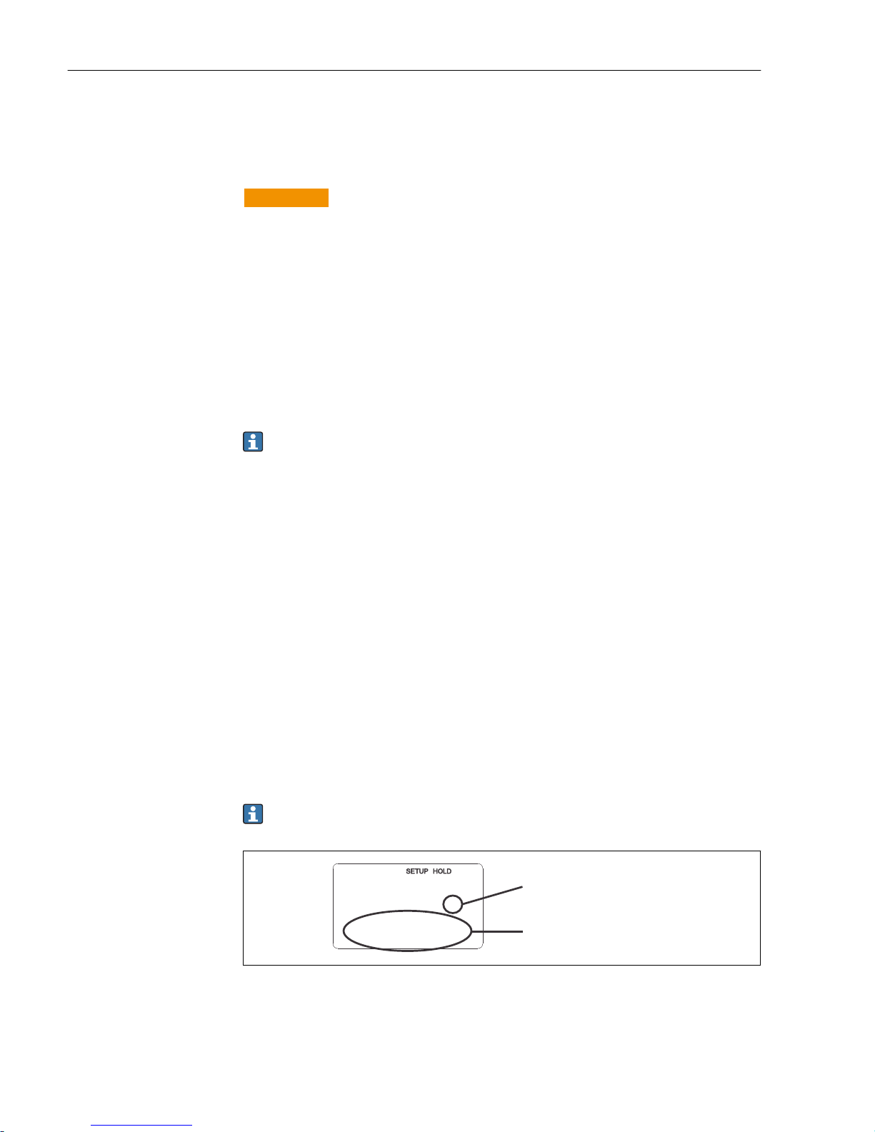
Function display:
The displayed code indicates
the function position in the
function group.
Additional information
2
A0025560-EN
20 Information for the user on the display
Page 33
Liquisys M CLM223/253 Commissioning
Endress+Hauser 33
C C1 C111
C121
C131
C132 C133
A0027502
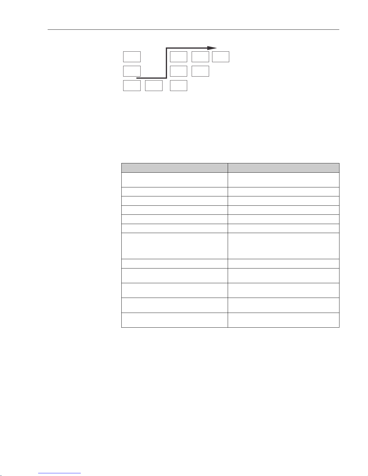
21 Function code
To make it easier for you to select and find function
groups and functions, a code for the corresponding
field is displayed for each function → 20
The structure of this code is illustrated in → 21.
The function groups are indicated as letters in the first
column (see the names of the function groups). The
functions of the individual groups are displayed
incrementally by row and by column.
Factory settings
The first time the device is switched on, the factory setting is set for all the functions. The
table below provides an overview of the most important settings.
All other factory settings can be found in the description of the individual function groups
in the "System configuration" section (the factory setting is highlighted in bold).
Function Factory setting
Type of measurement Conductive measurement of conductivity,
Temperature measurement in °C
Type of temperature compensation Linear with reference temperature 25 °C (77 °F)
Temperature compensation Automatic (ATC on)
Limit value for controller 1 9999 mS/cm
Limit value for controller 2 9999 mS/cm
Hold Active during configuration and calibration
Measuring range 0 μS/cm to 2000 mS/cm (no measuring ranges to be
configured).
The setting is flowing and depends on the sensors
connected.
Current outputs 1 and 2* 4 to 20 mA
Current output 1: measured value for 4 mA signal
current
0 μS/cm
Current output 1: measured value for 20 mA signal
current
2000 mS/cm
Current output 2: temperature value for 4 mA signal
current*
-35.0 °C (-31 °F)
Current output 2: temperature value for 20 mA
signal current*
250.0 °C (482 °F)
* with appropriate version
Page 34
Commissioning Liquisys M CLM223/253
34 Endress+Hauser
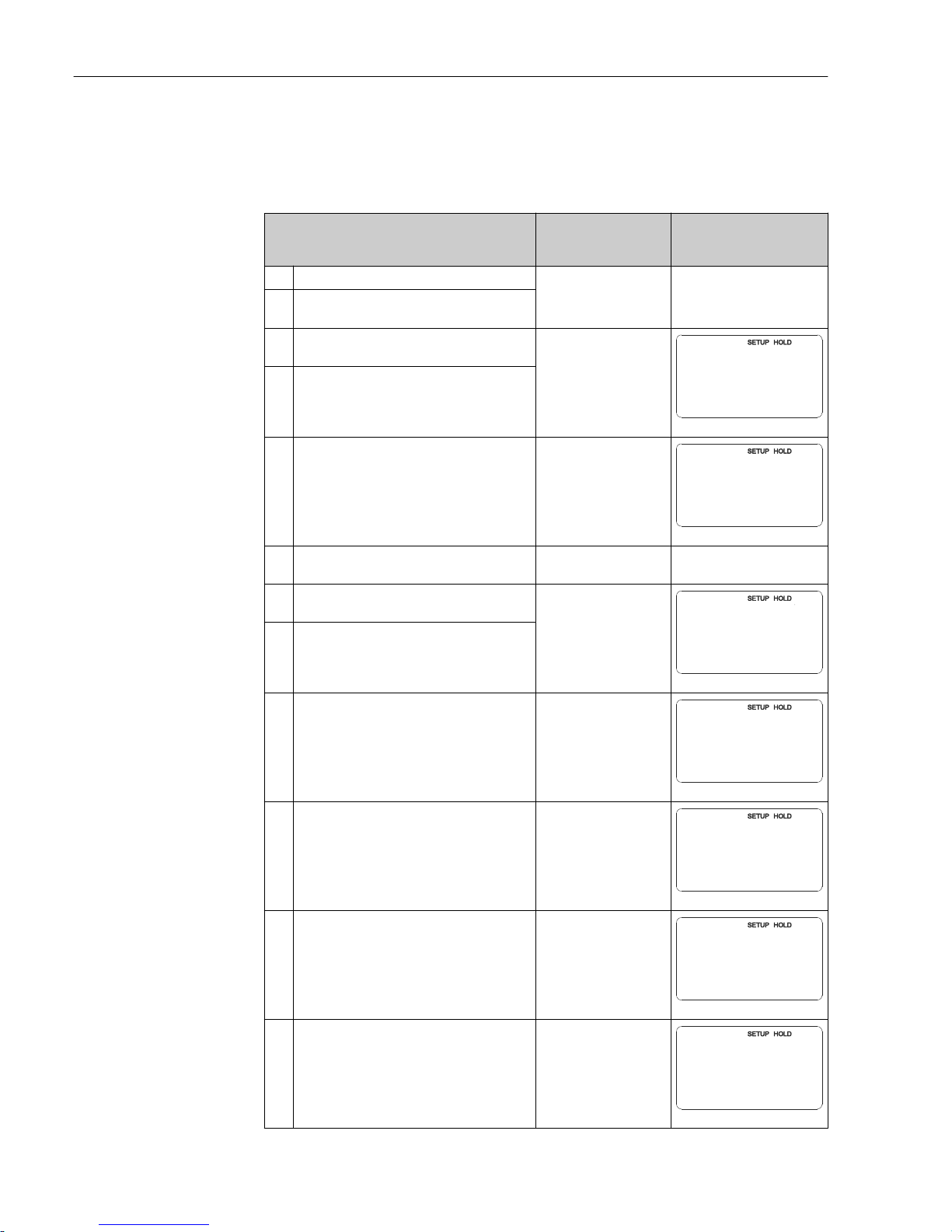
7.3 Quick Setup
After power-up, you must make some settings to configure the most important functions
of the transmitter which are required for correct measurement. The following section gives
an example of this.
User entry Range of adjustment
(factory settings in
bold)
Display
1. Press the ENTER key
2. Enter the code 22 to open access to the
menus. Press the ENTER key.
3. Press the MINUS key until you get to the
"Service" function group.
S
SERVICE
A0008408-EN
4. Press ENTER to be able to make your settings.
5. Select your language in S1, e.g. "ENG" for
English.
Press ENTER to confirm your entry.
ENG = English
GER = German
FRA = French
ITA = Italian
NEL = Dutch
ESP = Spanish
S1
Language
ENG
A0008409-EN
6. Press the PLUS and MINUS key simultaneously
to exit the "Service" function group.
7. Press the MINUS key until you get to the
"Setup 1" function group.
A
SETUP 1
A0007824-EN
8. Press ENTER to be able to make your settings
for "Setup 1".
9. In A1, select the desired mode of operation,
e.g. "cond" = conductive.
Press ENTER to confirm your entry.
cond = conductive
ind = inductive
MOhm = resistance
Conc = concentration
A1
Oper.Mode
cond
A0009002-EN
10. In A2, press ENTER to accept the factory
setting. (Only if A1 = conc, otherwise continue
with Step 12)
%
ppm
mg/l
TDS = total dissolved
solids
None
A2
Conc.Unit
%
A0009003-EN
11. In A3, press ENTER to accept the standard
setting.
XX.xx
X.xxx
XXX.x
XXXX
A3
Format
XX.xx
A0009004-EN
12. In A4, press ENTER to accept the standard
setting.
auto, μS/cm, mS/cm,
S/cm, μS/m, mS/m, S/ m
A4
Unit
auto
A0009005-EN
Page 35
Liquisys M CLM223/253 Commissioning
Endress+Hauser 35
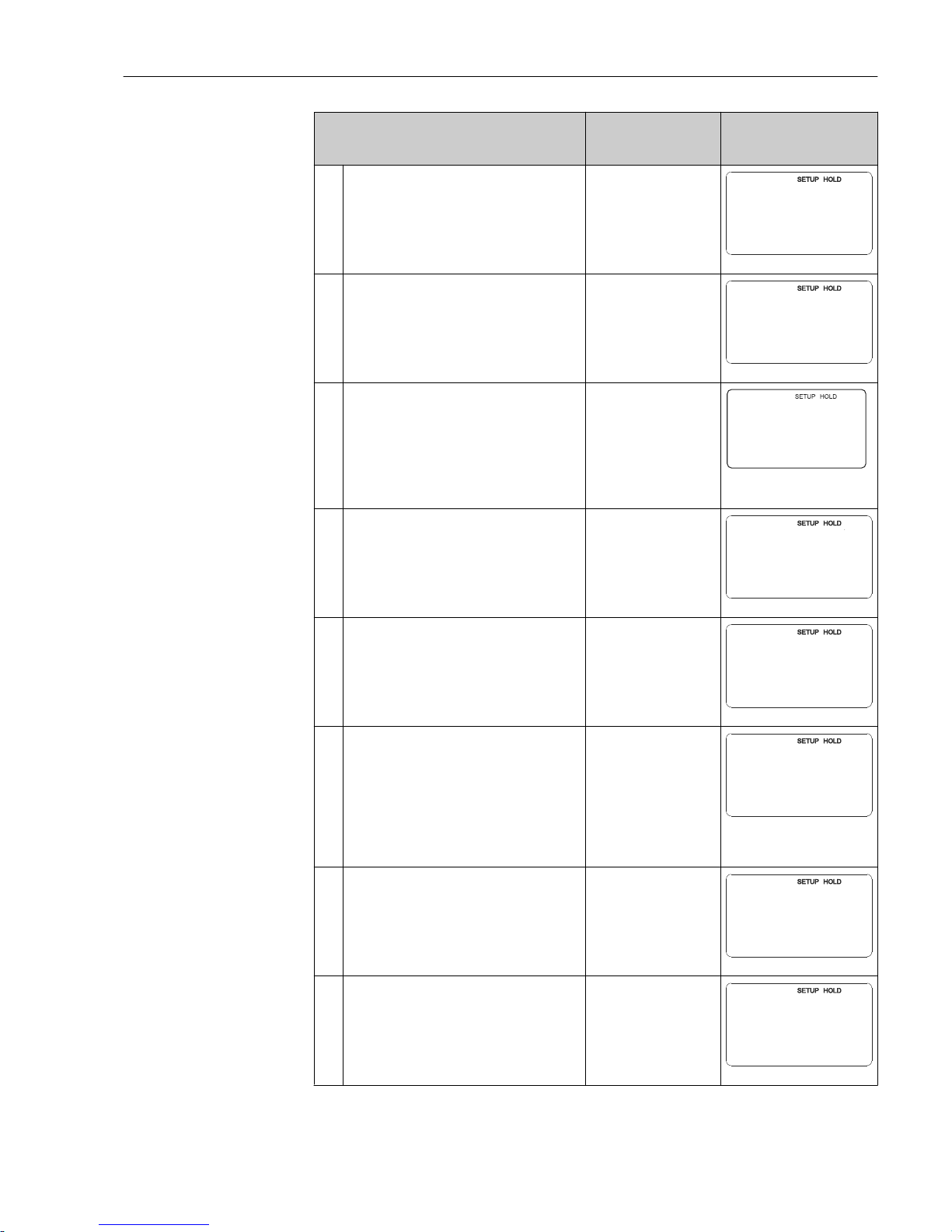
User entry Range of adjustment
(factory settings in
bold)
Display
13. In A5, enter the exact cell constant of the
sensor. The cell constant is provided on the
sensor quality certificate.
cond: 1.000 cm
-1
ind: 1.98 cm
-1
MOhm: 0.01 cm
-1
0.0025 to 99.99 cm
-1
A5
1/cm
Cellconst
1.000
A0009006-EN
14. In A6, enter the cable resistance (only applies
to conductive sensors).
0 Ω
0 to 99.99 Ω
A60
@
Cable-Res
A0009007-EN
15. In A7, enter the measured value damping.
Measured value damping causes the measured
value to be averaged over the specified number
of individual measured values (if A7 = 1, no
damping takes place).
Press ENTER to confirm your entry.
The display returns to the initial display of the
"Setup 1" function group.
1
1 to 60
A7
Damping
1
A0001960-EN
16. Press the MINUS key until you get to the
"Setup 2" function group.
Press ENTER to make your settings for "Setup
2".
B
SETUP 2
A0007830-EN
17. In B1, select the temperature sensor.
Press ENTER to confirm your entry.
Pt100
Pt1k = Pt 1000
NTC30
Fixed
B1
ProcTemp.
Pt100
A0009010-EN
18. In B2, select the appropriate type of
temperature compensation for your process,
e.g. "lin" = linear.
Press ENTER to confirm your entry.
Detailed information is provided in the "Setup
2" section.
None
Lin = linear
NaCl = table salt (IEC
746)
Pure = ultrapure water
NaCl
PureH = ultrapure water
HCl
Tab = table
B2
TempComp.
lin
A0009011-EN
19. In B3, enter the temperature coefficient α.
Press ENTER to confirm your entry.
2.1 %/K
0.0 to 20.0 %/K
B3
%/K
Alpha val
2.10
A0009012-EN
20. The current temperature is displayed in B5. If
necessary, adjust the temperature sensor to an
external measurement.
Press ENTER to confirm your entry.
Actual value displayed
and entered
-35.0 to 250.0 °C
B5
¡C
RealTemp.
0.0
A0009014-EN
Page 36
Commissioning Liquisys M CLM223/253
36 Endress+Hauser
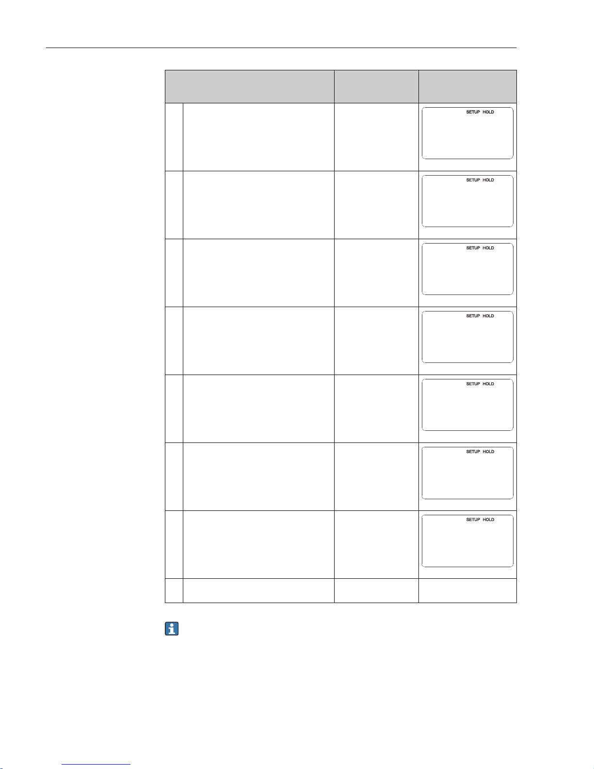
User entry Range of adjustment
(factory settings in
bold)
Display
21. The difference between the measured and
entered temperature is displayed.
Press the ENTER key.
The display returns to the initial display of the
"Setup 2" function group.
0.0 °C
-5.0 to 5.0 °C
B6
¡C
TempOffs.
0.0
A0009015-EN
22. Press the MINUS key to get to the "Current
output" function group.
Press ENTER to make your settings for the
current outputs.
O
OUTPUT
A0025026-EN
23. In O1, select your current output, e.g. "Out 1" =
output 1.
Press ENTER to confirm your entry.
Out 1
Out 2
O1
Sel.Out
Out1
A0025027-EN
24. In O3, select the linear characteristic.
Press ENTER to confirm your entry.
Lin = linear (1)
Lin = linear (1)
Tab = table
O3
Sel.Type
lin
A0025029-EN
25. In O311, select the current range for your
current output, e.g. 4 to 20 mA.
Press ENTER to confirm your entry.
4 to 20mA
0 to 20 mA
O311
Sel.Range
4-20
A0025030-EN
26. In O312, specify the conductivity at which the
minimum current value is applied at the
transmitter output, e.g. 0 μS/cm.
Press ENTER to confirm your entry.
Cond/ind: 0.00 μS/cm
MOhm: 0.00 kΩ·cm
Conc: 0.00 %
Temp: 0.00 °C
O312
mg/l
0/4 mA
0.00
A0025031-EN
27. In O313, specify the conductivity at which the
maximum current value is applied at the
transmitter output, e.g. 2000 mS/cm.
Press ENTER to confirm your entry.
The display returns to the initial display of the
"Current output" function group.
Cond/ind: 2000 mS/cm
MOhm: 500 kΩ·cm
Conc: 99.99 %
Temp: 150 °C
O313
mg/l
20 mA
10.00
A0025032-EN
28. Press PLUS and MINUS simultaneously to
switch to the measurement mode.
You must perform an air set before installing the inductive sensor. See the
"Calibration" section for more information.
Page 37
Liquisys M CLM223/253 Commissioning
Endress+Hauser 37
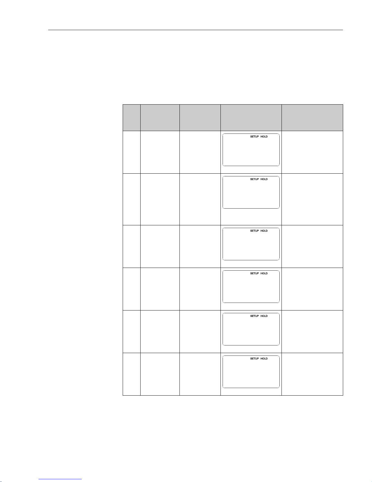
7.4 Device configuration
7.4.1 Setup 1 (conductivity)
In the SETUP 1 function group, you can change the settings for the measuring mode and
the sensor.
Functions marked in italics are not supported by the basic device version.
Coding Field Range of
adjustment
(factory settings
in bold)
Display Info
A
SETUP 1
function group
A
SETUP 1
A0007824-EN
Configuration of basic
functions
A1 Select the
operating mode
auswählen
cond = conductive
ind = inductive
MOhm =
resistance
conc=
concentration
A1
Oper.Mode
cond
A0009002-EN
Display varies depending on
the device:
• Cond/resistance/conc
• Ind/conc
When the operating
mode is changed, all
user settings are
automatically reset.
A2 Select the
concentration unit
to be displayed
(only for Plus
Package)
%
ppm
mg/l
TDS = total
dissolved solids
None
A2
Conc.Unit
%
A0009003-EN
A2 is only active if A1 = conc
A3 Select the display
format for the
concentration unit
(only for Plus
Package)
XX.xx
X.xxx
XXX.x
XXXX
A3
Format
XX.xx
A0009004-EN
A3 is only active if A1 = conc
A4 Select the unit to
be displayed
auto, μS/cm,
mS/cm, S/cm, μS/
m, mS/m, S/m,
kΩ·cm, MΩ·cm,
kΩ·m
A4
Unit
auto
A0009005-EN
If "auto" is selected, the
highest possible resolution is
automatically selected.
A4 is not active if A1 = conc
A5 Enter the cell
constant for the
connected sensor
cond:1.000 cm
-1
ind:1.98 cm
-1
MOhm:0.01 cm
-1
0.0025 to 99.99
cm
-1
A5
1/cm
Cellconst
1.000
A0009006-EN
The exact cell constant is
provided on the sensor
quality certificate.
Page 38
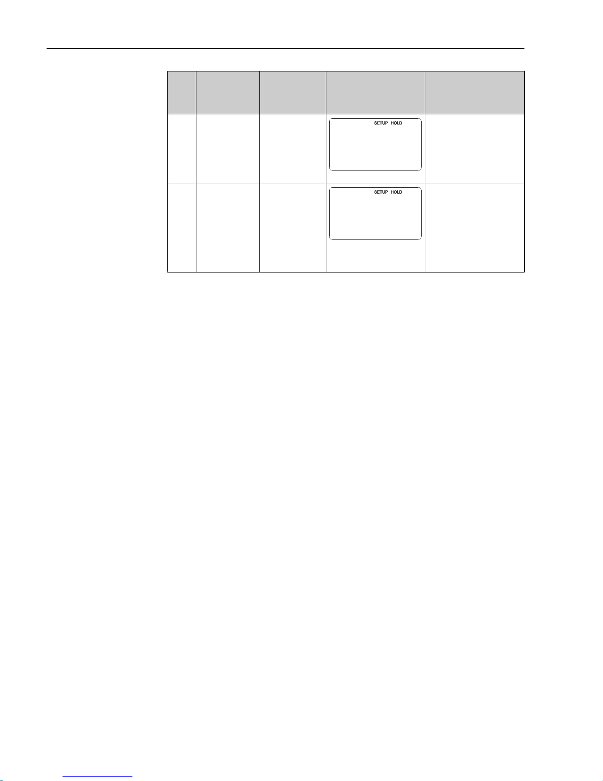
Commissioning Liquisys M CLM223/253
38 Endress+Hauser
Coding Field Range of
adjustment
(factory settings
in bold)
Display Info
A6 Enter the cable
resistance
0 Ω
0 to 99.99 Ω
A60
@
Cable-Res
A0009007-EN
Only for conductive sensors.
The standardized line
resistance must be multiplied
by the actual cable length.
CYK71: 0.165 Ω/m
A7 Enter the value
for measured
value damping
1
1 to 60
A7
Damping
1
A0009008-EN
Measured value damping
causes averaging over the
specified number of
individual measured values.
This is used, for example, to
stabilize the display if the
measurement is unstable.
There is no damping if “1” is
entered.
Page 39
Liquisys M CLM223/253 Commissioning
Endress+Hauser 39
7.4.2 Setup 2 (temperature)
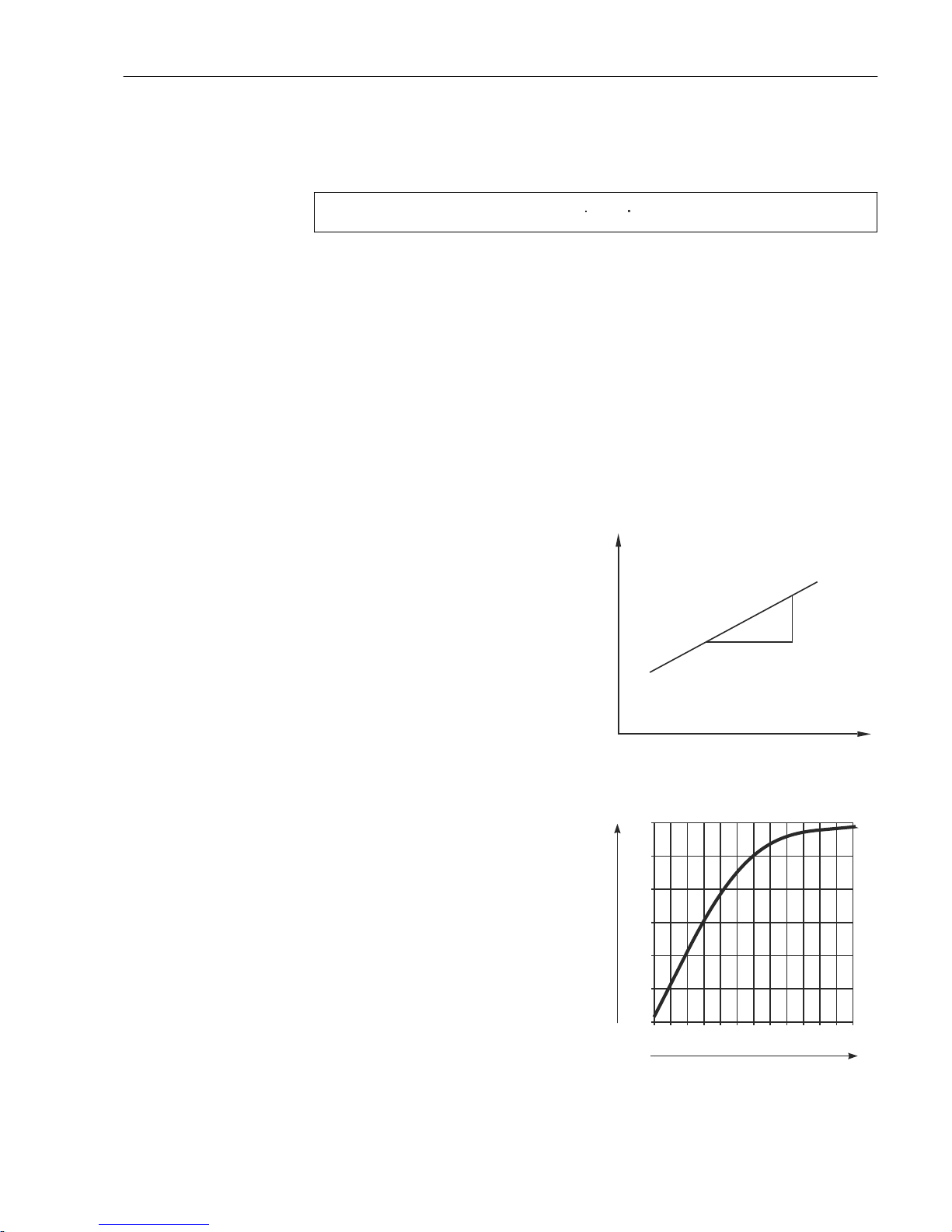
Temperature coefficient α indicates the change in the conductivity per degree of
temperature change:
k(T) k(T )
0
(1+
=
(T - T ))
0
a
.
.
A0009163
Where
κ(T) = conductivity at process temperature T
κ(T0) = conductivity at reference temperature T
0
The temperature coefficient depends both on the chemical composition of the solution and
the temperature itself.
To determine the level of dependency, four different types of compensation can be selected
in the transmitter:
• Linear temperature compensation
• NaCl compensation
• NaCl ultrapure water compensation (neutral compensation)
• HCl ultrapure water compensation (acid compensation)
• Temperature compensation with table
Linear temperature compensation
The change between two temperature points is taken
to be constant, i.e. α = const. The α value can be edited
for linear compensation. The reference temperature
can be edited in the B7 field. The default setting is 25
°C.
1
a
T
k*
A0008945
22 Linear temperature compensation
* Uncompensated conductivity
NaCl compensationIn the case of NaCl compensation
(as per IEC 60746), a fixed non-linear curve specifying
the relationship between the temperature coefficient
and temperature is saved in the device. This curve
applies to low concentrations of up to approx. 5 %
NaCl.
0
48
96
144
2.1
2.3
2.5
2.7
T [°C]
a [%/K]
A0008939
23 NaCl compensation
Page 40
Commissioning Liquisys M CLM223/253
40 Endress+Hauser
Ultrapure water compensation (for conductive sensors)
For pure and ultrapure water, algorithms are saved in the transmitter that consider the
self-dissociation of ultra pure water and its strong temperature dependency. They are used
for conductivity levels of approx. 100 μS/cm.
Two types of compensation are available:
• NaCl ultrapure water compensation: this is optimized for pH-neutral contamination.
• HCl ultrapure water compensation: this is optimized for measuring the acid conductivity
downstream of a cation exchanger. It is also suitable for ammonia (NH3) and caustic
soda (NaOH).
• The ultrapure water compensation types always refer to a reference temperature of
25 °C (77 °F).
• The lowest conductivity displayed is the theoretical limit value of ultrapure water at
25 °C (77 °F) of 0.055 μS/cm.
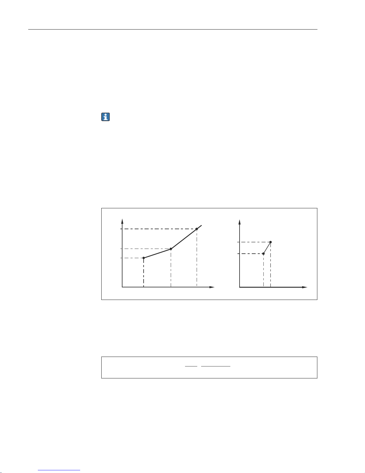
Temperature compensation with table
For devices with the Plus Package, it is possible to enter a table with temperature
coefficients α as a function of the temperature. The following conductivity data of the
medium under measurement are required to use the alpha table function for temperature
compensation:
Value pairs comprising the temperature T and conductivity κ with:
• κ(T0) for the reference temperature T
0
• κ(T) for the temperatures that occur in the process
T
1
T
0
T
2
T T
k
2
k
1
k
k( )
T
0
T1T
2
a
1
a
2
a
A
B
A0008944
24 Determination of the temperature coefficient
A Required data
B Calculated α values
Use the following formula to calculate the α values for the temperatures that are relevant
in your process:
a =
100%
k(T )
0
k k(T) - (T )
0
T - T
0
.
; T T¹
0
A0009162
Enter the α-T value pairs obtained in this way in the T4 and T5 fields of the ALPHA TABLE
function group.
Use this function group to change the settings for temperature measurement.
Page 41
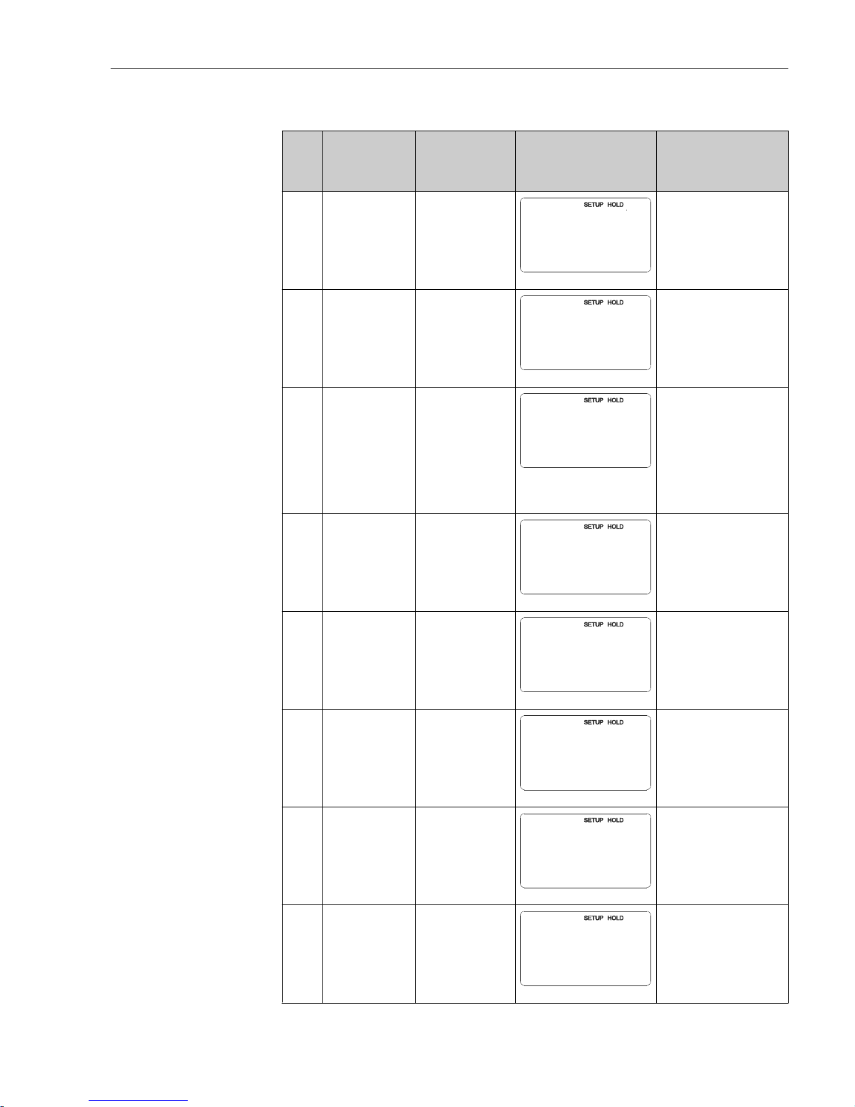
Liquisys M CLM223/253 Commissioning
Endress+Hauser 41
Functions marked in italics are not supported by the basic device version.
Coding Field Range of
adjustment
(factory settings in
bold)
Display Info
B
SETUP 2 function
group
B
SETUP 2
A0007830-EN
Settings for temperature
measurement
B1 Select the
temperature
sensor
Pt100
Pt1k = Pt 1000
NTC30
Fixed
B1
ProcTemp.
Pt100
A0009010-EN
"fixed":
Manual temperature
compensation (MTC), no
temperature measurement.
Instead a fixed temperature
value is defined in B4.
B2 Select the type of
temperature
compensation
None
Lin = linear
NaCl = table salt
(IEC 746)
Pure = ultrapure
water NaCl
PureH = ultrapure
water HCl
Tab = Table
B2
TempComp.
lin
A0009011-EN
This option does not
appear for concentration
measurement.
"Pure" and "PureH" are only
displayed for conductive
devices.
B3 Enter temperature
coefficient α
2.10 %/K
0.00 to 20.00 %/K
B3
%/K
Alpha val
2.10
A0009012-EN
Only if B2 = lin.
With other settings in B2,
field B3 does not have any
effect.
B4 Enter the process
temperature
25.0 °C
-35.0 to 250.0 °C
B4
¡C
ProcTemp.
25.0
A0009013-EN
Only if B1 = fixed.
The value entered can only
be in °C.
B5 Display the
temperature and
adjust the
temperature
sensor
Actual value
displayed and
entered
-35.0 to 250.0 °C
B5
¡C
RealTemp.
0.0
A0009014-EN
With the value entered
here, the temperature
sensor can be adjusted to
an external measurement.
Affects B6.
Omitted if B1 = fixed.
B6 Enter the
temperature
differential
(offset)
Current offset
-5.0 to 5.0 °C
B6
¡C
TempOffs.
0.0
A0009015-EN
The offset is the difference
between the actual value
entered and the measured
temperature.
Omitted if B1 = fixed.
B7 Enter reference
temperature
25.0 °C
-5.0 to 100 °C
B7
C
°
ref temp.
25.0
A0009016-EN
Page 42
Commissioning Liquisys M CLM223/253
42 Endress+Hauser
7.4.3 Current input
For the "Current input" function group, you require a relay card with a current input which
is not available in the basic device version. With this function group, you can monitor
process parameters and use them for feedforward control. For this purpose, you must
connect the current output of an external measured variable (e.g. flowmeter) to the 4 to
20mA input of the transmitter. The following assignment applies:
Flow in main stream Current signal in mA Current input signal in %
Flowmeter start of measuring range 4 0
Flowmeter end of measuring range 20 100
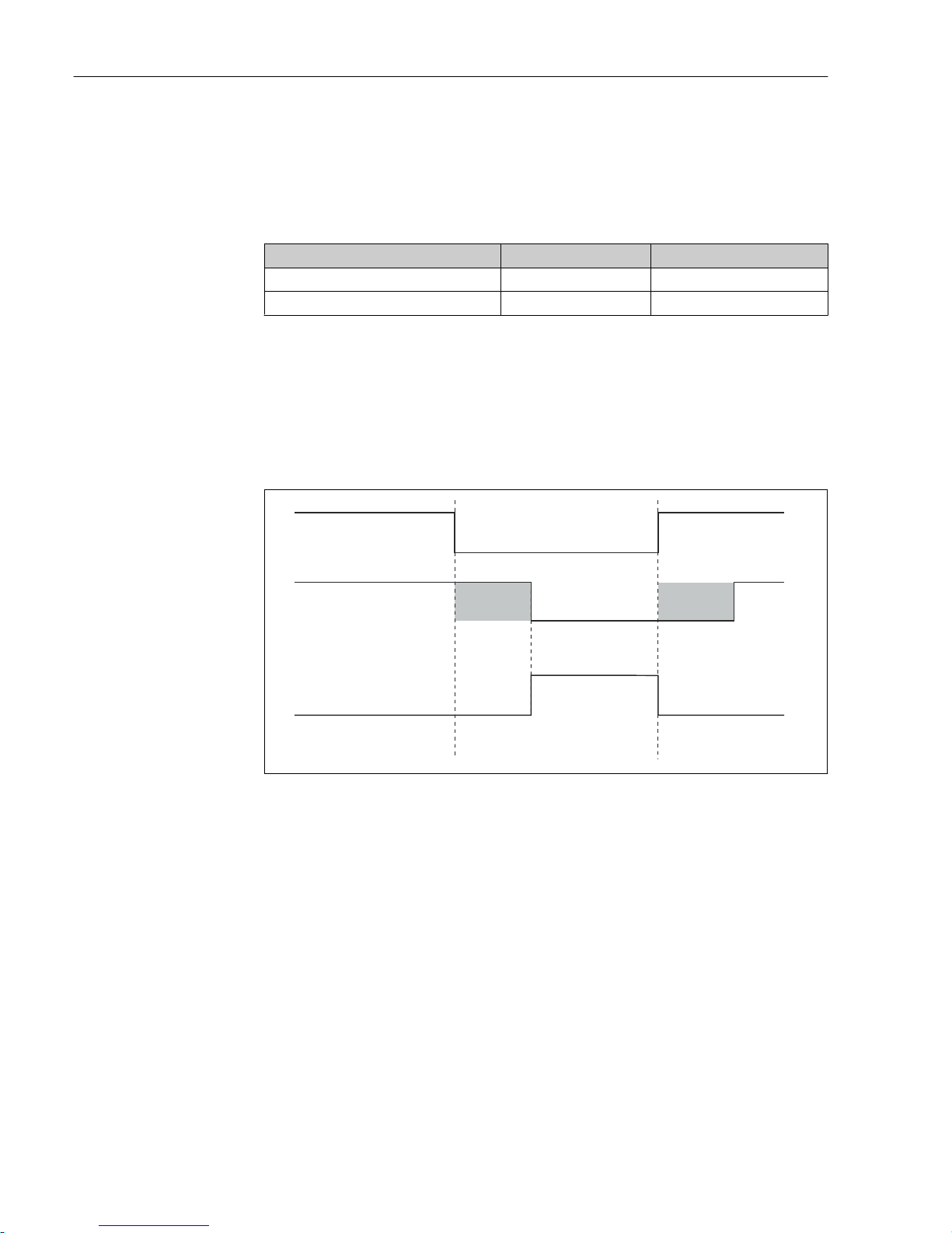
Flow monitoring in the main stream
This arrangement is particularly practical if the sample flow through a flow assembly in an
open outlet is independent of the flow in the main stream.
This permits signaling of an alarm condition in the main stream (flow too low or has
completely stopped) and triggers dosing switch-off even if the medium flow is maintained
due to the method of installation.
A
E
D
F
C
B
1
0
0
0
1
1
Z2 Z3
A0008923
25 Alarm signaling and dosing switch-off by the main stream
A Flow in main stream F Flow restoration
B Relay contacts of PID controller Z2 Delay for controller switch-off, see field Z2
C Alarm relay Z3 Delay for controller switch-on, see field Z3
D Flow below switch-off limit Z 4 or flow failure 0 Off
E Flow alarm 1 On
Feedforward control to PID controller
You can optimize control on control systems with very short response times by measuring
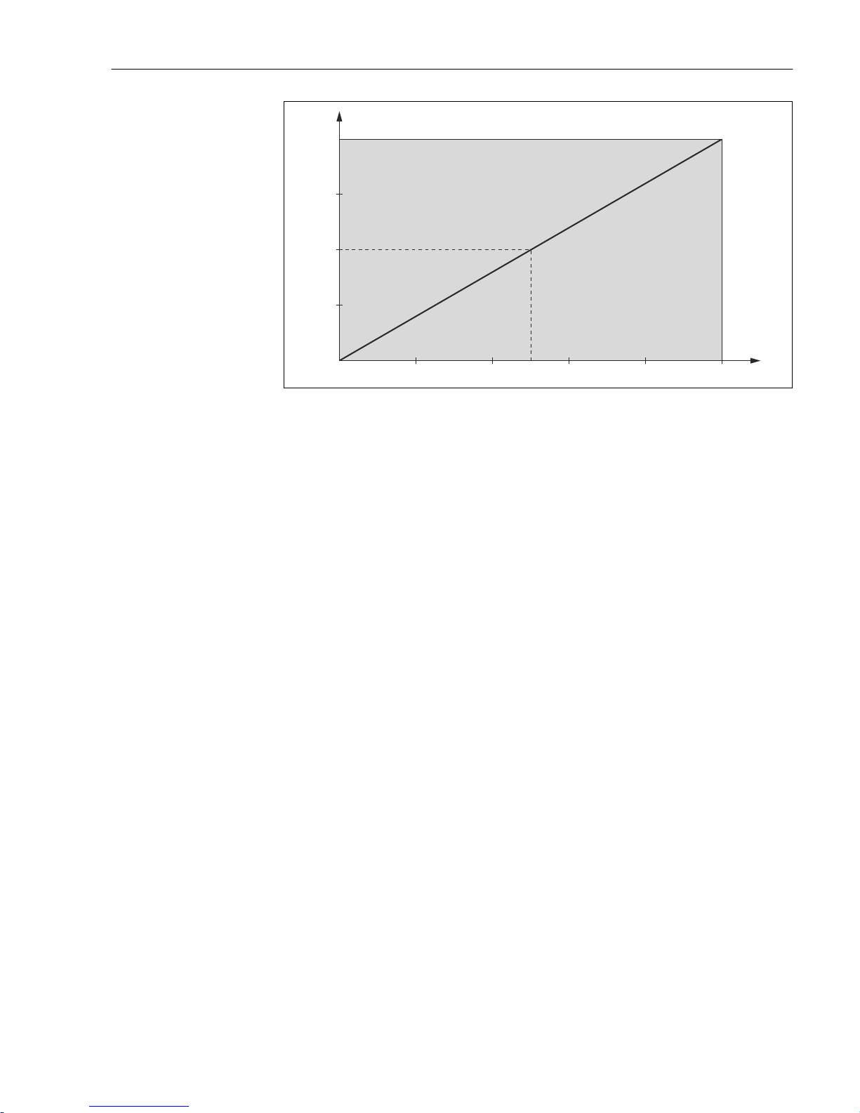
the medium flow rate in addition to the oxygen content. Then apply this flow rate value (4
to 20 mA) as feedforward control to the PID controller.
Feedforward control is a multiplying function as illustrated in the figure below (example
with factory setting):
Page 43
Liquisys M CLM223/253 Commissioning
Endress+Hauser 43
1
0 20 40 60 80 100Z7
1.5
0.5
Y
X
A0008942
26 Multiplying feedforward control
Y Gain K
infl
X Current input signal in [%]
Page 44
Commissioning Liquisys M CLM223/253
44 Endress+Hauser
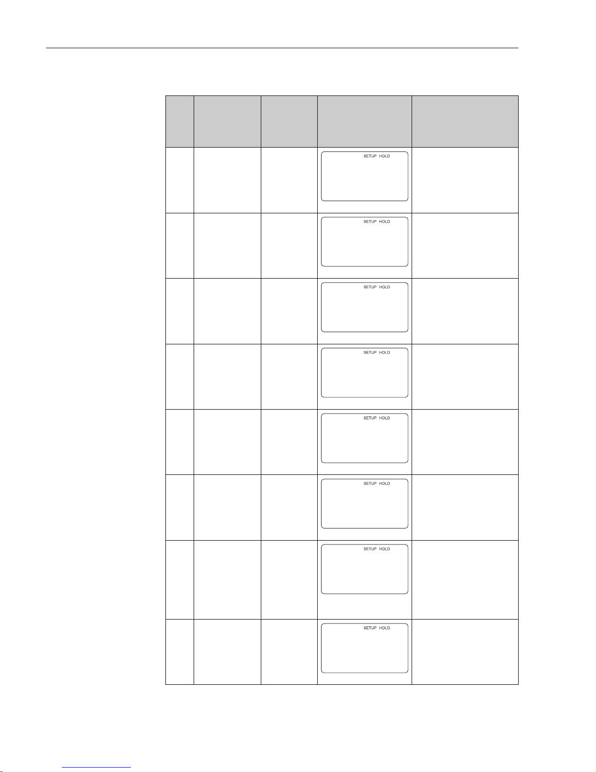
Functions marked in italics are not supported by the basic device version.
Coding Field Range of
adjustment
(factory
settings in
bold)
Display Info
Z
CURRENT INPUT
function group
Z
CUR.INPUT
A0024903-EN
Current input settings
Z1 Select flow
monitoring of main
stream (with
controller switchoff)
Off
On
Z1
Cont.stop
Off
A0024904-EN
Flow monitoring may only be
switched on if the flowmeter is
connected in the main stream. If
Z1 = off, fields Z2 to Z5 are not
available.
Z2 Enter the delay for
controller switchoff through current
input
0 s
0 to 2000 s
Z2
s
Off Delay
0
A0024905-EN
Brief flow shortfalls can be
suppressed by this delay and do
not result in controller switchoff.
Z3 Enter the delay for
controller switchon through current
input
0 s
0 to 2000 s
Z3
s
On Delay
0
A0024934-EN
In the case of a controller, a
delay until the reception of a
representative measured value
is recommended after a long
period without flow.
Z4 Enter the switch-off
limit value for the
current input
50 %
0 to 100 %
Z4
%
A.Thresh
50
A0024935-EN
0 to 100% corresponds to 4 to
20 mA at the current input.
Observe measured value
assignment to the current
output of the flowmeter.
Z5 Enter the switch-off
direction for the
current input
Low
High
Z5
Stop Dir
Low
A0024939-EN
The controller is switched off if
the value entered in Z4 is
undershot or overshot.
Z6 Select feedforward
control to PID
controller
Off
Lin = linear
Basic
Z6
PID influ
Off
A0024940-EN
If Z6 = off, the field Z7 is not
available.
Z6 = basic: disturbance variable
only affects the basic load
(alternatively dosing in
proportion to quantity, if usual
PID controller not possible, e.g.
defective sensor).
Z7 Enter value for
feedforward control
at which gain = 1
applies
50 %
0 to 100 %
Z7
%
Kinflu=1
50
A0024941-EN
When the value is set, the
controller actuating variable is
the same size when feedforward
control is switched on as when
feedforward control is switched
off.
Page 45
Liquisys M CLM223/253 Commissioning
Endress+Hauser 45
7.4.4 Current outputs
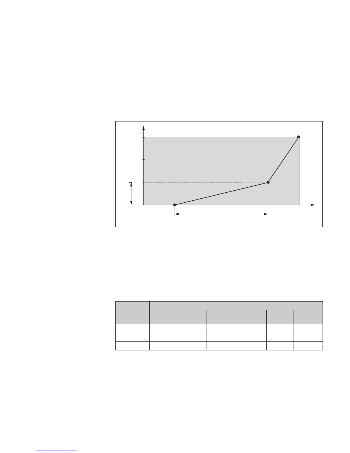
Use the "Current output" function group to configure the individual outputs. You can enter
either a linear characteristic (O3 (1)) or a user-defined current output characteristic in
conjunction with the Plus Package (O3 (3)). Exception: if you have chosen a "continuous
controller" for current output 2, you cannot enter a user-defined current output
characteristic for this current output.
In addition, you can also simulate a current output value (O3 (2)) to check the current
outputs.
If a second current output is present, you can output the controller actuating variable via
the current output in accordance with field R237/O2.
1500
1000
2000
500
0 4 8 12 16 20
I [mA]
D I [mA]
D Signal
[mS/cm]c
A0008943
27 User-defined current output characteristic (example)
The current output characteristic must increase or decrease very monotonically.
The distance per mA between two table value pairs must be greater than:
• Conductivity: 0.5 % of measuring range
• Temperature: 0.25 °C
The values for the sample characteristic → 27 are entered in the following table. The
distance per mA is calculated from Δ signal / Δ mA.
Current output 1 Current output 2
Value pair [mS/cm]
[%] [°C]
Current
[mA]
Distance
per mA
[mS/cm]
[%] [°C]
Current
[mA]
Distance
per mA
1 500 4
2 1000 16 41.66
3 2000 20 250
Page 46
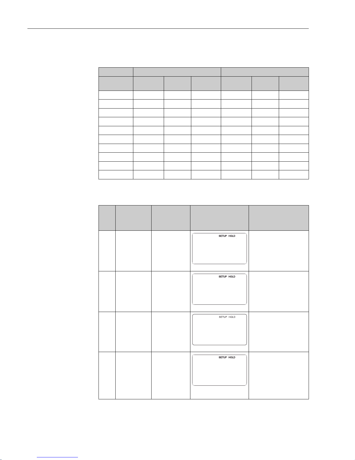
Commissioning Liquisys M CLM223/253
46 Endress+Hauser
First enter the desired current output configuration into the following blank table with a
pencil. Calculate the resulting signal distance per mA to observe the necessary minimum
slope. Then enter the values in the device.
Current output 1 Current output 2
Value pair [mS/cm]
[%] [°C]
Current
[mA]
Distance
per mA
[mS/cm]
[%] [°C]
Current
[mA]
Distance
per mA
1
2
3
4
5
6
7
8
9
10
Functions marked in italics are not supported by the basic device version.
Coding Field Range of
adjustment
(factory settings
in bold)
Display Info
O
CURRENT
OUTPUT
function group
O
OUTPUT
A0025026-EN
Configuration of the current
output (does not apply for
PROFIBUS).
O1 Select current
output
Out 1
Out 2
O1
Sel.Out
Out1
A0025027-EN
A characteristic can be
selected for every output.
O2 Select measured
variable for 2nd
current output
°C
mS/cm, MΩ, %
Contr
O2
Parameter
¡C
A0025028-EN
R237=curr (current output 2)
can only be selected if
O2=Contr (controller) is
selected (relay card required).
O3 (1) Enter the
characteristic
type
Lin = linear (1)
Sim = simulation
(2)
Tab = table (3)
O3
Sel.Type
lin
A0025029-EN
The characteristic can have a
positive or negative slope for
the measured value output.
In the case of actuating
variable output (O2 = Contr),
an increasing current
corresponds to an increasing
actuating variable.
Page 47
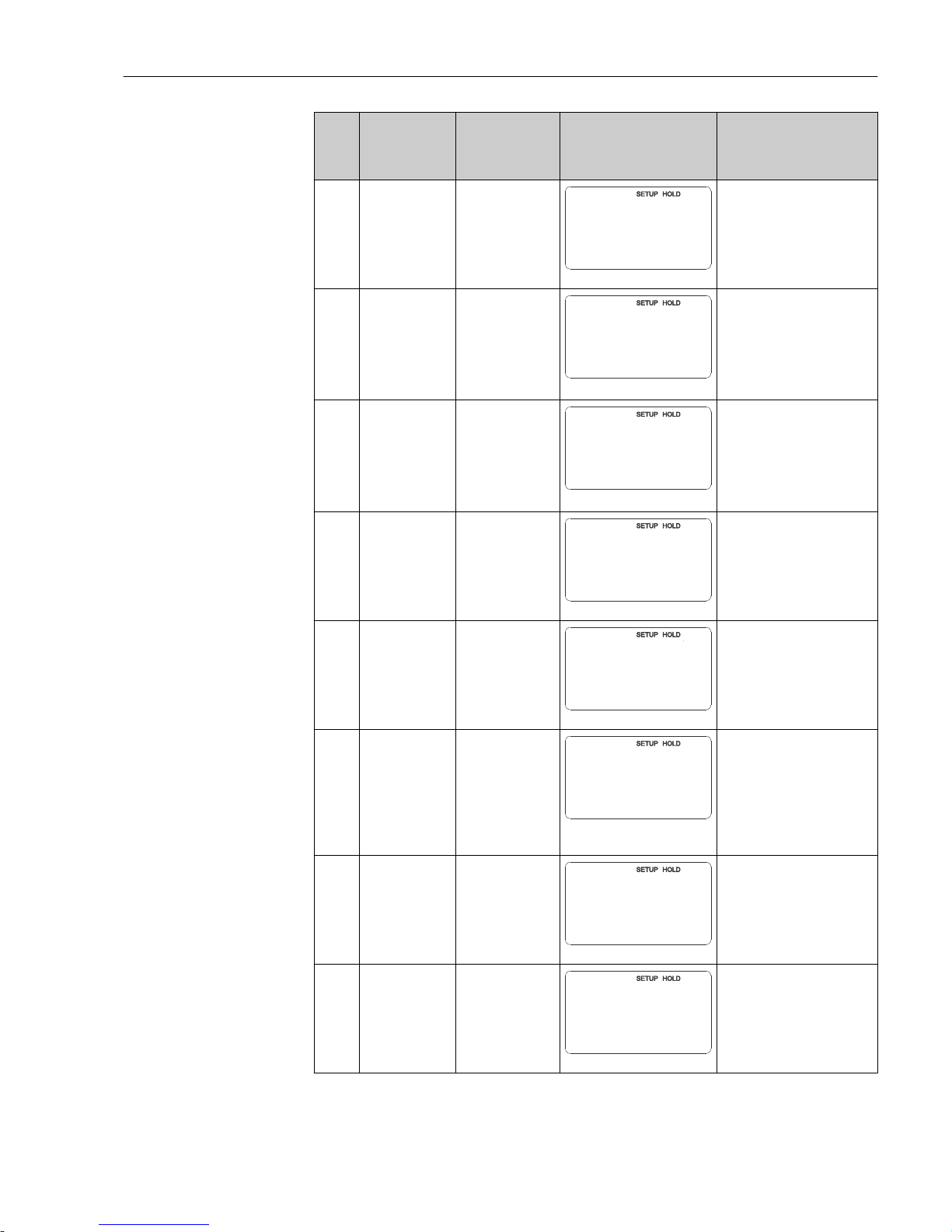
Liquisys M CLM223/253 Commissioning
Endress+Hauser 47
Coding Field Range of
adjustment
(factory settings
in bold)
Display Info
O311 Select current
range
4 to 20mA
0 to 20 mA
O311
Sel.Range
4-20
A0025030-EN
O312 0/4 mA value:
Enter the
associated
measured value
Cond/ind: 0.00
μS/cm
MOhm:
0.00kΩ*cm
Conc: 0.00 %
Temp: 0.00 °C
µS/cm
O312
0/4 mA
0.00
A0025034-EN
Here you can enter the
measured value at which the
min. current value (0/4 mA)
is applied at the transmitter
output (not for controller).
(Turndown see Technical
data.)
O313 20 mA value:
Enter the
associated
measured value
Cond/ind: 2000
μS/cm
MOhm: 500
kΩ*cm
Conc: 99.99 %
Temp: 150 °C
mS/cm
O313
20 mA
2000
A0025035-EN
Here you can enter the
measured value at which the
max. current value (20 mA) is
applied at the transmitter
output (not for controller).
(Turndown see Technical
data.)
O3 (2) Simulate current
output
Lin = linear (1)
Sim = simulation
(2)
Tab = table (3)
O3
Sel.Type
sim
A0025039-EN
Simulation is not ended until
O3(1) or O3(3) is selected.
For further characteristics, see
O3 (1), O3 (3).
O321 Enter simulation
value
Current value
0.00 to 22.00 mA
O321
mA
Simulat.
10.20
A0025040-EN
Entering a current value
results in this value being
directly output at the current
output.
O3 (3) Enter current
output table
Lin = linear (1)
Sim = simulation
(2)
Tab = table (3)
O3
Sel.Type
table
A0025041-EN
Only for Plus Package
Values can also be
subsequently added or
modified. The values entered
are automatically sorted by
increasing current value.
For further characteristics, see
O3 (1), O3 (2).
O331 Select table
option
Read
Edit
O331
Sel.Table
read
A0025042-EN
O332 Enter number of
table value pairs11 to 10
O332
No.Elem.
1
A0025043-EN
Enter the number of pairs of x
and y values (measured value
and current value) here.
Page 48
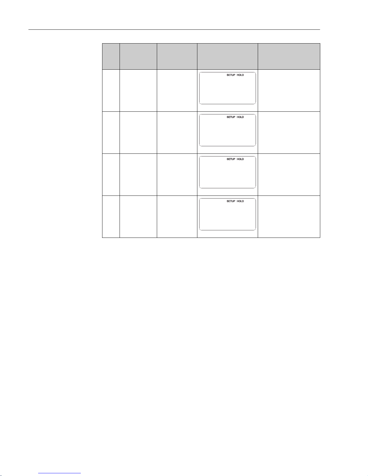
Commissioning Liquisys M CLM223/253
48 Endress+Hauser
Coding Field Range of
adjustment
(factory settings
in bold)
Display Info
O333 Select table value
pair
1
1 to no. elem.
Assign
O333
Sel.Elem.
1
A0025044-EN
The system runs through the
O333 to O335 function chain
as often as indicated in O332.
"Assign" appears as the last
step. The display goes to
O336 after confirmation.
O334 Enter x value Cond/ind: 0.00
μS/cm
MOhm:
0.00kΩ*cm
Conc: 0.00 %
Temp: 0.00 °C
O334
µS/cm
Meas.val.
0.00
A0025045-EN
x value = measured value
specified by user.
O335 Enter y value 0.00 mA
0.00 to 20.00 mA
O335
mA
mA value
0.00
A0025048-EN
y value = user-defined current
value pertaining to O334.
Return to O333 until all
values are entered.
O336 Message as to
whether table
status is OK
Yes
No
O336
Status ok
yes
A0025049-EN
Back to O3.
If status = no, correct the table
(all settings made up until
now remain intact) or go back
to the measuring mode (table
is deleted).
Page 49
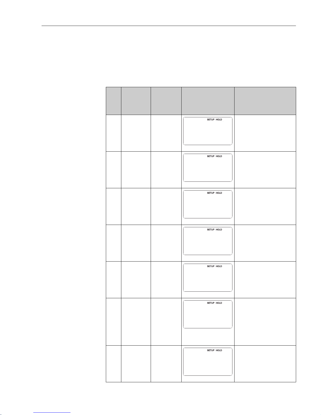
Liquisys M CLM223/253 Commissioning
Endress+Hauser 49
7.4.5 Alarm
You can use the "Alarm" function group to define various alarms and configure output
contacts.
Each individual error can be defined to be effective or not (at the contact or as an error
current).
Functions marked in italics are not supported by the basic device version.
Coding Field Range of
adjustment
(factory
settings in
bold)
Display Info
F
ALARM
function group
F
ALARM
A0025141-EN
Alarm function settings.
F1 Select contact
type
Latch =
latching
contact
Momen =
momentary
contact
F1
Cont.Type
Latch
A0025142-EN
The option selected only applies
for the fault-signaling contact, not
for the error current.
F2 Select the time
unit for the
alarm delay
s
min
F2
Time Unit
s
A0025143-EN
F3 Enter alarm
delay
0 s (min)
0 to 2000 s
(min)
F3
s
Err.Delay
0
A0025144-EN
Depending on the option selected
in F2, the alarm delay can be
entered in s or min.
F4 Select error
current
22 mA
2.4 mA
F4
Err.Curr
22mA
A0025145-EN
If "0-20 mA" was selected in
O311, "2.4 mA" may not be
used.
F5 Select the error
number
1
1 to 255
F5
Sel.error
1
A0025146-EN
Here you can select all the errors
which should trigger an alarm. The
errors are selected by the error
numbers. Please refer to the table
in the "System error messages"
section for the meaning of the
individual error numbers. The
factory settings remain in effect
for all errors that are not edited.
F6 Set alarm
contact to be
effective for the
selected error
Yes
No
F6
Rel.Assg
yes
A0025147-EN
If “no” is selected, all the other
alarm settings are deactivated (e.g.
alarm delay). The settings
themselves are maintained. This
setting only applies to the error
currently selected in F5.
Page 50
Commissioning Liquisys M CLM223/253
50 Endress+Hauser
Coding Field Range of
adjustment
(factory
settings in
bold)
Display Info
F7 Set error
current to be
effective for the
selected error
No
Yes
F7
Curr.Assg
no
A0025148-EN
The option selected in F4 is
effective or not effective in the
event of an error.
This setting only applies to the
error currently selected in F5.
F8 Automatic
cleaning
function start
No
Yes
F8
CleanTrig
no
A0025149-EN
This field is not available for
certain errors, see the
"Troubleshooting and fault
elimination" section.
F9 Select return to
menu or next
error
Next = next
error number
←R
F9
Select
next
A0025150-EN
If ←R is selected, you return to F. If
Next is selected, you go to F5.
7.4.6 Check
The CHECK function group is only available for devices with a Plus Package.
In the CHECK function group, you can select different monitoring functions for the
measurement.
Polarization detection (field P1)
In the case of conductive sensors, the effects of polarization in the boundary layer between
the sensor and medium restrict the measuring range. The transmitter can detect
polarization effects by using a smart signal analysis process. Error message E071 is
displayed.
Alarm threshold monitoring (fields P2 to P5)
You can use this function to monitor the measured value for permissible upper and lower
limits and trigger an alarm (error messages E154, E155).
PCS alarm (process check system), (fields P6 to P9)
AC (alternation check; sensor activity monitoring): The function AC (field P6) is used to
check measuring signals for deviations. An alarm (E152) is triggered if the measuring
signal remains constant within the space of one hour. The reason for such sensor behavior
can be contamination, cable open circuit or similar.
CC (controller check): You can monitor the controller activity with the CC function . This
function is primarily suited to batch operation and single-sided limit switches. A
malfunction of the controller is detected and reported thanks to freely adjustable
monitoring times (E156, E157).
Page 51
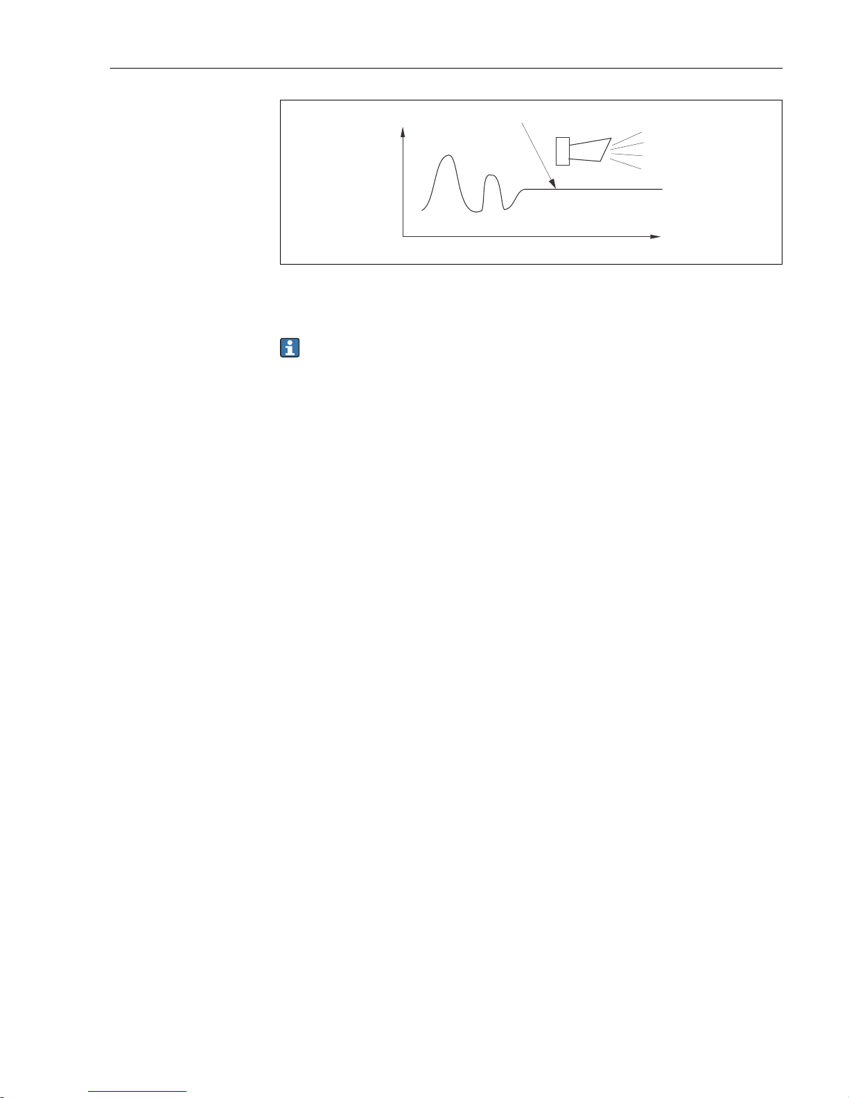
Liquisys M CLM223/253 Commissioning
Endress+Hauser 51
A
t
A0025196
28 PCS alarm (live check)
A Constant measuring signal = alarm triggered after PCS alarm time has elapsed
Any PCS alarm pending is automatically deleted as soon as the sensor signal changes.
Page 52
Commissioning Liquisys M CLM223/253
52 Endress+Hauser
You can use the "Check" function group to monitor the measured value for permissible
upper and lower limits and trigger an alarm.
Functions marked in italics are not supported by the basic device version.
Coding Field Range of
adjustment
(factory settings
in bold)
Display Info
P
CHECK function
group
P
CHECK
A0009045-EN
Settings for sensor and
process monitoring
P1 Switch
polarization
detection on or off
(only for
conductive
sensors)
Off
On
P1
Pol.Detec
Off
A0009046-EN
Polarization only occurs with
conductive sensors.
Any polarization that may
occur is detected but is not
compensated for. (Error no.:
E071)
P2 Select alarm
threshold
monitoring
Off
Low
High
LoHi = low and
high
Lo!
Hi!
LoHi!
P2
A.Tresh
Off
A0009048-EN
Alarm possible with or
without controller switch-off.
xxxx = without controller
switch-off
xxxx! = with controller
switch-off
(Error no.: E154, E155)
P3 Enter alarm delay 0 min (s)
0 to 2000 min (s)
P3
s
Err.Delay
0
A0009049-EN
Depending on the option
selected in F2, the alarm
delay can be entered in s or
min.
This delay must first elapse
before undershooting/
overshooting in accordance
with fields P4/P5 results in
an alarm.
P4 Enter lower alarm
threshold
0 µS/cm
0 to 9999 mS/cm
P4
µS/cm
LowAlarm
0.00
A0009050-EN
P5 Enter upper alarm
threshold
9999 µS/cm
0 to 9999 mS/cm
P5
mS/cm
HighAlarm
9999
A0009051-EN
P6 Select process
monitoring
Off
AC
CC
AC+CC
AC!
CC!
AC+CC!
P6
ProcMonit
Off
A0009052-EN
AC = sensor activity
monitoring (E152)
CC = controller monitoring
(E156, E157)
Alarm possible with or
without simultaneous
controller switch-off.
xxxx = without controller
switch-off
xxxx! = with controller
switch-off
Page 53
Liquisys M CLM223/253 Commissioning
Endress+Hauser 53
Coding Field Range of
adjustment
(factory settings
in bold)
Display Info
P7 Enter maximum
permissible
duration for lower
CC setpoint limit
violation (field
P9)
60 min
0 to 2000 min
P7
min
Tmax Low
60
A0009053-EN
Only if P6=CC or AC CC.
P8 Enter maximum
permissible
duration for upper
CC setpoint limit
violation (field
P9)
120 min
0 to 2000 min
P8
min
Tmax High
120
A0009054-EN
Only if P6=CC or AC CC.
P9 Enter CC set point
(for P7/P8)
1000 µS/cm
0 to 9999 mS/cm
P9
µS/cm
Setpoint
1000
A0009055-EN
Set value is an absolute value.
This function is primarily
suited to batch operation and
single-sided limit switches.
7.4.7 Relay configuration
For the "RELAY" function group, you require a relay card which is not available in the basic
device version.
The following relay contacts can be selected and configured as desired (max. four contacts,
depending on options installed):
• Limit contactor for conductivity measured value: R2 (1)
• Limit contactor for temperature: R2 (2)
• PID controller: R2 (3)
• Timer for cleaning function: R2 (4)
• Chemoclean function: R2 (5)
• USP/EP: R2 (6) and R2 (7) (for Plus Package, only conductive sensors)
Limit contactor for conductivity measured value and temperature
The transmitter has different ways of assigning a relay contact. Switch-on and switch-off
points and pickup and dropout delays can be assigned to the limit contactor. In addition,
you can configure an alarm threshold to output an error message and to start a cleaning
function in conjunction with this.
These functions can be used both for the primary value and for temperature measurement.
Please refer to the switch states in → 29 for a clear illustration of the relay contact
states.
• When the measured values increase (maximum function), the relay contact is closed as
of t2 after the switch-on point (t1) has been exceeded and the pickup delay has elapsed
(t2-t1).
The alarm contact switches if the alarm threshold (t3) is reached and the alarm delay
(t4-t3) has also elapsed (errors E067 to E070).
• When the measured values decrease, the alarm contact is reset when the value falls
below the alarm threshold (t5) again, as is the relay contact (t7) after the dropout delay
(t7-t6).
• If the pickup and dropout delays are set to 0 s, the switch-on and switch-off points are
also switch points of the contacts.
The same settings can also be made for a minimum function in the same way as for the
maximum function.
Page 54
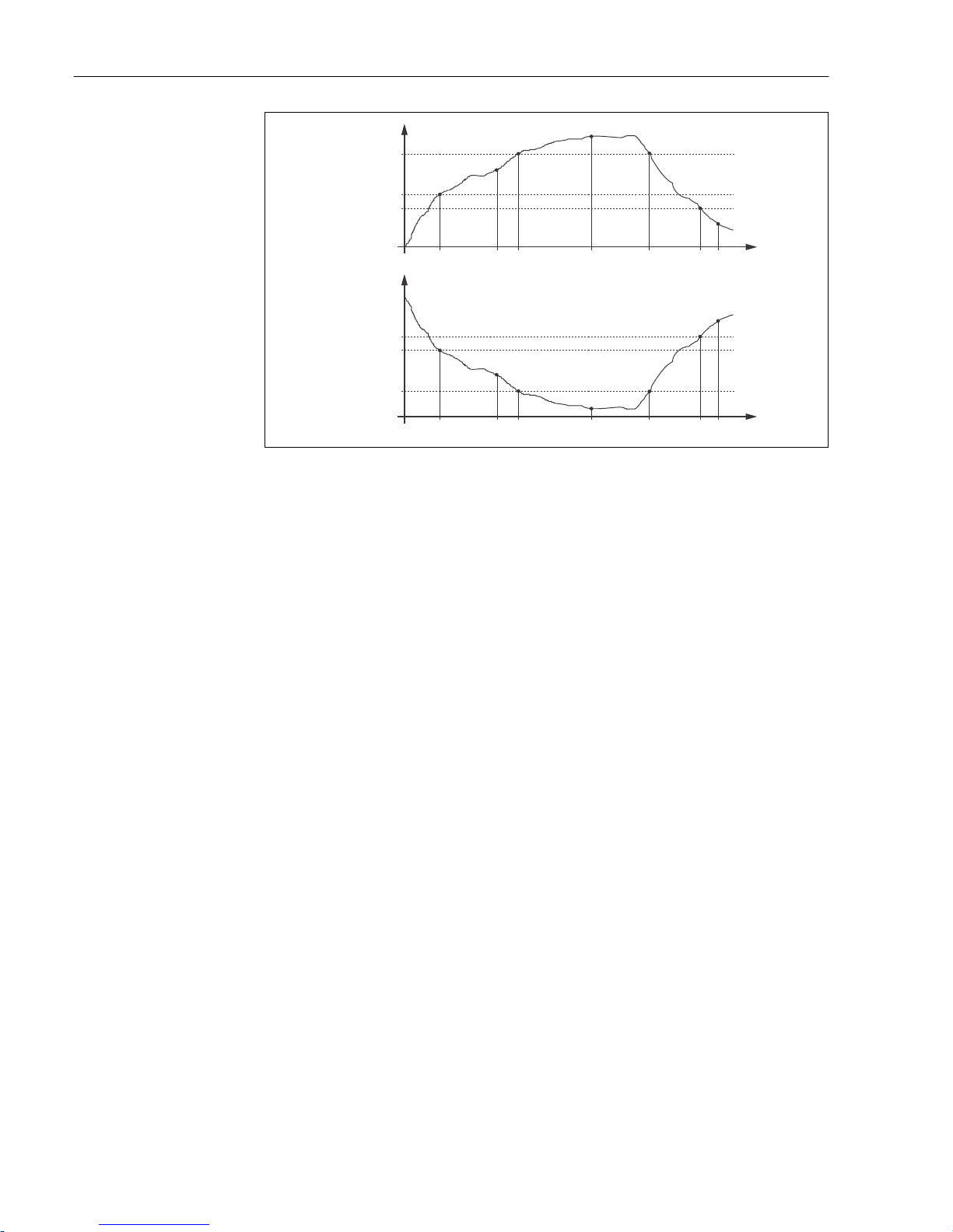
Commissioning Liquisys M CLM223/253
54 Endress+Hauser
t
1
t
1
t
2
t
2
t
3
t
3
t
4
t
4
t
5
t
5
t
6
t
6
t
7
t
7
t
t
B
1
2
3
3
2
1
4
5
6
7
4
5
6
7
A
A0025215
29 Illustration of the alarm and limit value functions
A Switch-on point > switch-off point: Max. function
B Switch-on point < switch-off point: Min. function
1 Alarm threshold
2 Switch-on point
3 Switch-off value
4 Contact ON
5 Alarm ON
6 Alarm OFF
7 Contact OFF
Page 55
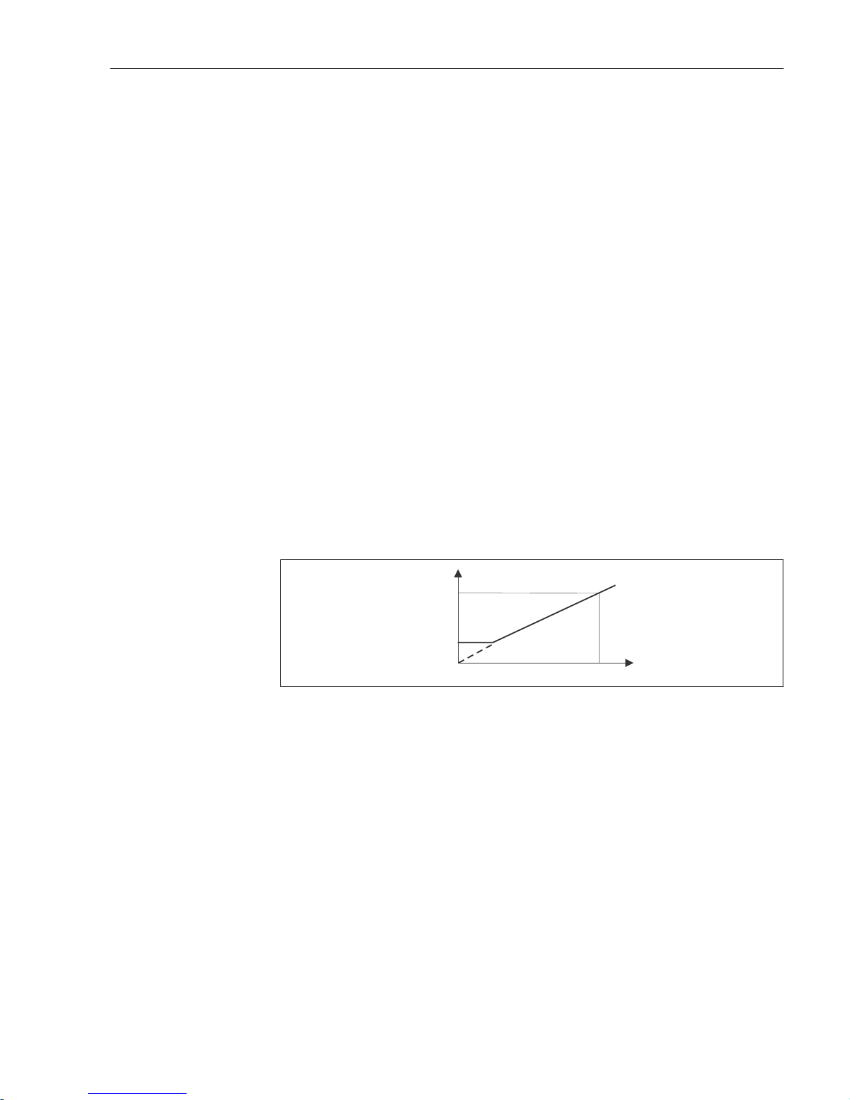
Liquisys M CLM223/253 Commissioning
Endress+Hauser 55
P(ID) controller
You can define various controller functions for the transmitter. On the basis of the PID
controller, P, PI, PD and PID controllers can be implemented. For an optimum control
system, use the controller that best suits your application.
• P controller
Used for simple linear control purposes with small system deviations. Where major
changes are to be controlled, overshooting may occur. In addition, a lasting control
deviation must be expected.
• PI controller
Is used for control systems where overshooting is to be avoided and no lasting control
deviation should occur.
• PD controller
Is used for processes that require quick changes and where peaks must be corrected.
• PID controller
Is used for processes where a P, PI or PD controller does not control sufficiently.
Configuration options of the P(ID) controller
The following configuration options are available for a PID controller:
• Change control gain Kp (P influence)
• Set integral action time Tn (I influence)
• Set derivative action time Tv (D influence)
Basic load dosing (basic)
You can set a constant dosage amount (field R2311) with basic load dosing (field R231).
PID control plus basic load dosing
If you have selected this function (PID + Basic) in field R231, the PID-controlled dosage
amount does not drop below the basic load value entered in field R2311.
100 %
100 %
A
B
C
A0025221
30 Control characteristic of PID controller with basic load dosing
A PID plus basic load
B Basic load
C PID
Commissioning
If you do not yet have any experience for setting the control parameters, set the values
that yield the greatest possible stability in the control circuit. Proceed as follows to
optimize the control circuit further:
• Increase the control gain Kp until the controlled variable just starts to overshoot.
• Reduce Kp slightly again and then reduce the integral action time Tn so that the shortest
possible correction time without overshooting is achieved.
• To reduce the response time of the controller, also set the derivative action time Tv.
Control and fine optimization of the set parameters with a recorder
Page 56
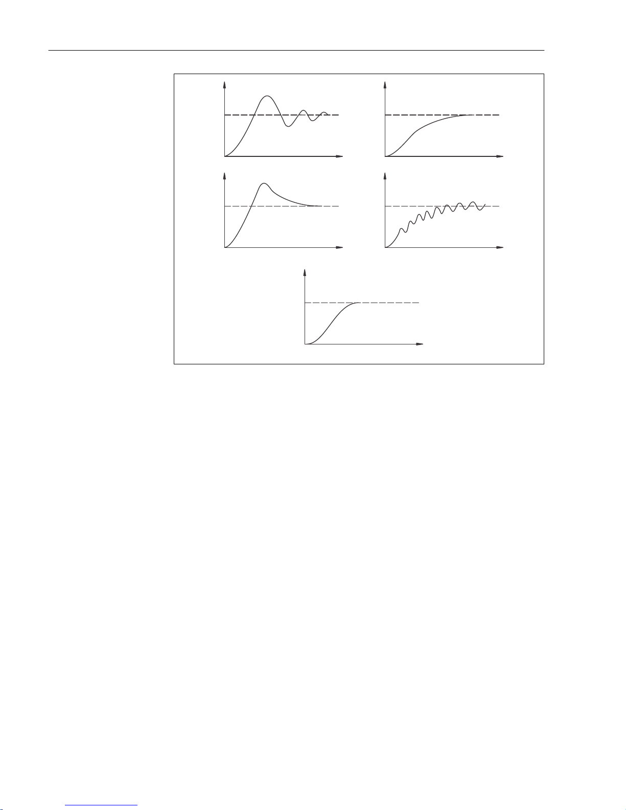
Commissioning Liquisys M CLM223/253
56 Endress+Hauser
A
B
A
B
A
B
A
B
A
B
1
2
3
4
5
A0025218
31 Optimization of settings Tn and K
p
A Actual value
B Time
1 Tn too small
2 Tn too large
3 Kp too large
4 Kp too small
5 Optimum setting
Actuating signal outputs via contacts (R237 to R2310)
Each control contact outputs a cyclical signal whose intensity corresponds to the
controller's actuating value. A distinction is made according to the type of signal cycle:
• Pulse length modulation
The bigger the calculated manipulated variable is, the longer the contact affected
remains picked up. The period T can be set to be between 0.5 and 99 s (field R238).
Outputs with pulse length modulation are used to activate solenoid valves.
• Pulse frequency modulation
The bigger the calculated manipulated variable is, the higher the switching frequency of
the contact affected. The maximum switching frequency 1/T can be set to be between 60
and 180 min-1 (field R239). The on-time ton is constant. It depends on the set maximum
frequency and is approx. 0.5 s for 60 min-1 and approx. 170 ms for 180 min-1. 170 ms.
Outputs with pulse frequency modulation are used to activate directly controlled
solenoid dosing pumps.
Page 57
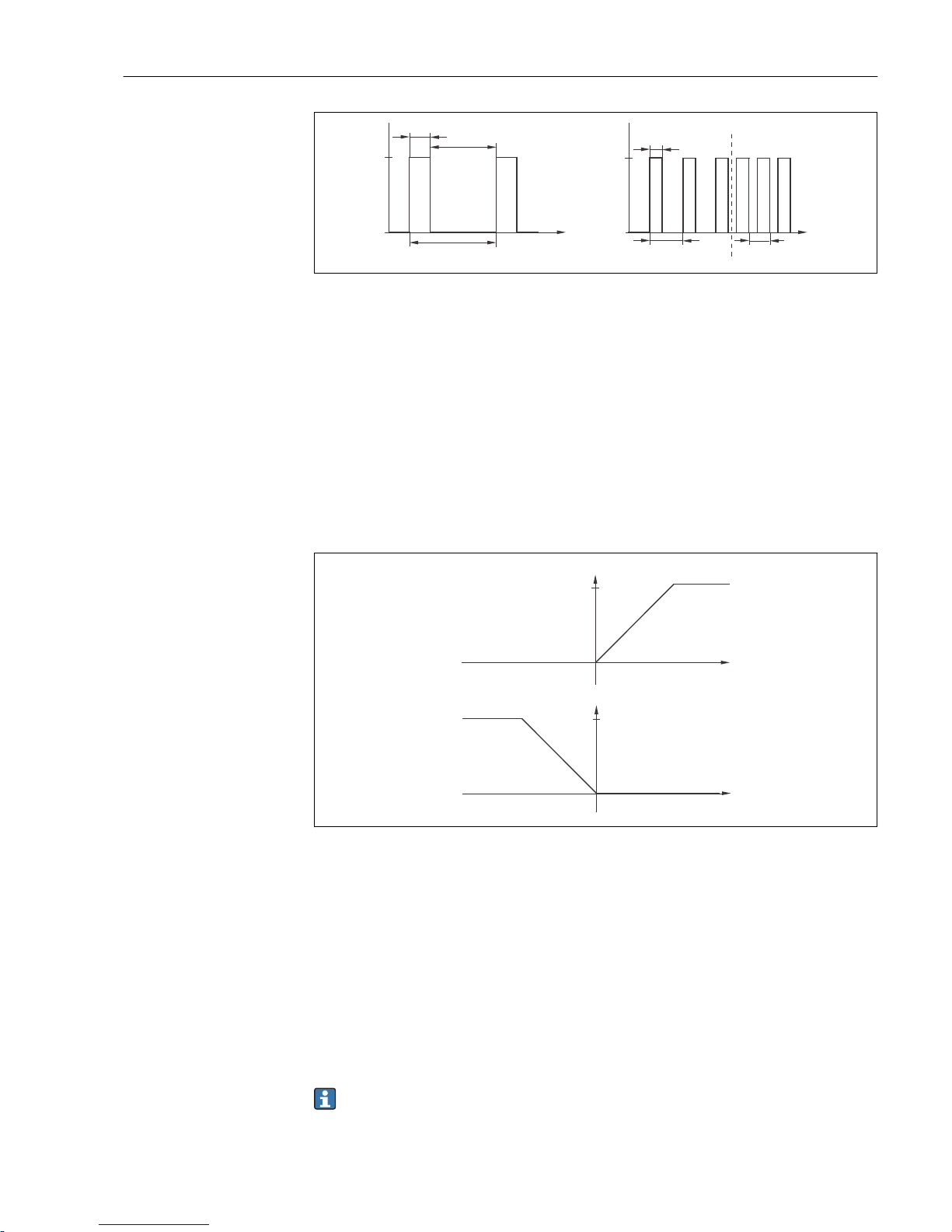
Liquisys M CLM223/253 Commissioning
Endress+Hauser 57
A
1
0
T
t [s]
A
t [s]
t
1
t
2
t
1
1
0
T
1
T
2
A0025219
32 Signal of a pulse-length modulated controller contact (left) and of a pulse frequency-modulated controller
contact (right)
Contact: 1 = on, 0 = off T Period
Time (s): t1 = ton t2 = t
off
T1 T2 Impulse period length ( 1/T1 and 1/T2)
Constant controller
The controller can also control the second analog current output (if provided). This is
configured in fields R237 and O2.
Control characteristic for direct and inverse control action
You can choose between two control characteristics in the R236 field:
• Direct control action = maximum function
• Inverse control action = minimum function
X
W
X
W
– X
W
– X
W
100 %
100 %
Y
Y
A
B
A0025222
33 Control characteristic of a proportional controller with direct and inverse control action
A Direct = maximum function
B Inverse = minimum function
XW Control deviation
Y Current output signal = controller actuating variable
Timer for cleaning function
This function includes a simple cleaning option. You can set the time interval after which
cleaning should start. Therefore you can only select a constant interval sequence.
Other cleaning functions are available for selection in conjunction with the Chemoclean
function (device version with four contacts required, see the "Chemoclean function"
section).
The timer and Chemoclean do not work independently of one another. While one of
the two functions is active, the other cannot be started.
Page 58
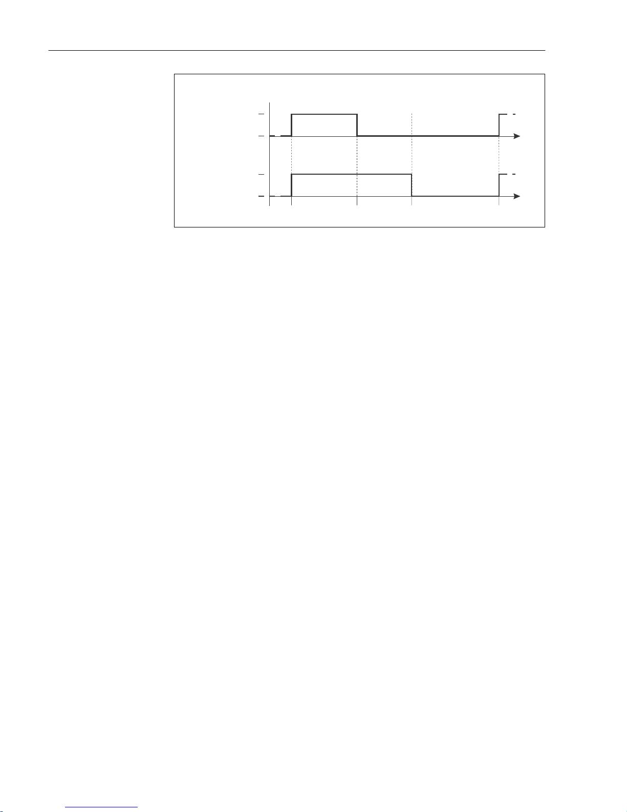
Commissioning Liquisys M CLM223/253
58 Endress+Hauser
A
B
1
0
t
1
t
2
1
0
t
3
t
t
t
4
t
0
A0025223
34 Connection between cleaning time, pause time and hold dwell period
A Wiper and/or spray cleaning system
B Hold function
0 Inactive
1 active
t0 Normal operation
t1 cleaning start
t2-t1Cleaning time
t3-t2Clean hold dwell period (0 to 999 s)
t4-t3Pause time between two cleaning intervals (1 to 7200 min)
Chemoclean function
Just like the timer function, Chemoclean can also be used to start a cleaning cycle.
However, Chemoclean also gives you the added option of defining various cleaning and
rinsing intervals and of dosing cleaning agent.
Therefore, it is possible to clean irregularly with different repeat cycles and to separately
set the cleaning times with post rinse times.
Please note the following:
• To use the Chemoclean function the transmitter has to be equipped with a designated
relay board (see product structure or chapter "accessories").
• The timer and Chemoclean are mutually dependent. While one of the two functions is
active, the other cannot be started.
• For the Chemoclean function, the relays 3 (water) and 4 (cleaner) are used.
• If the cleaning is prematurely aborted, a post rinse time always follows.
• If the setting is "Economy", cleaning only takes place with water.
Page 59
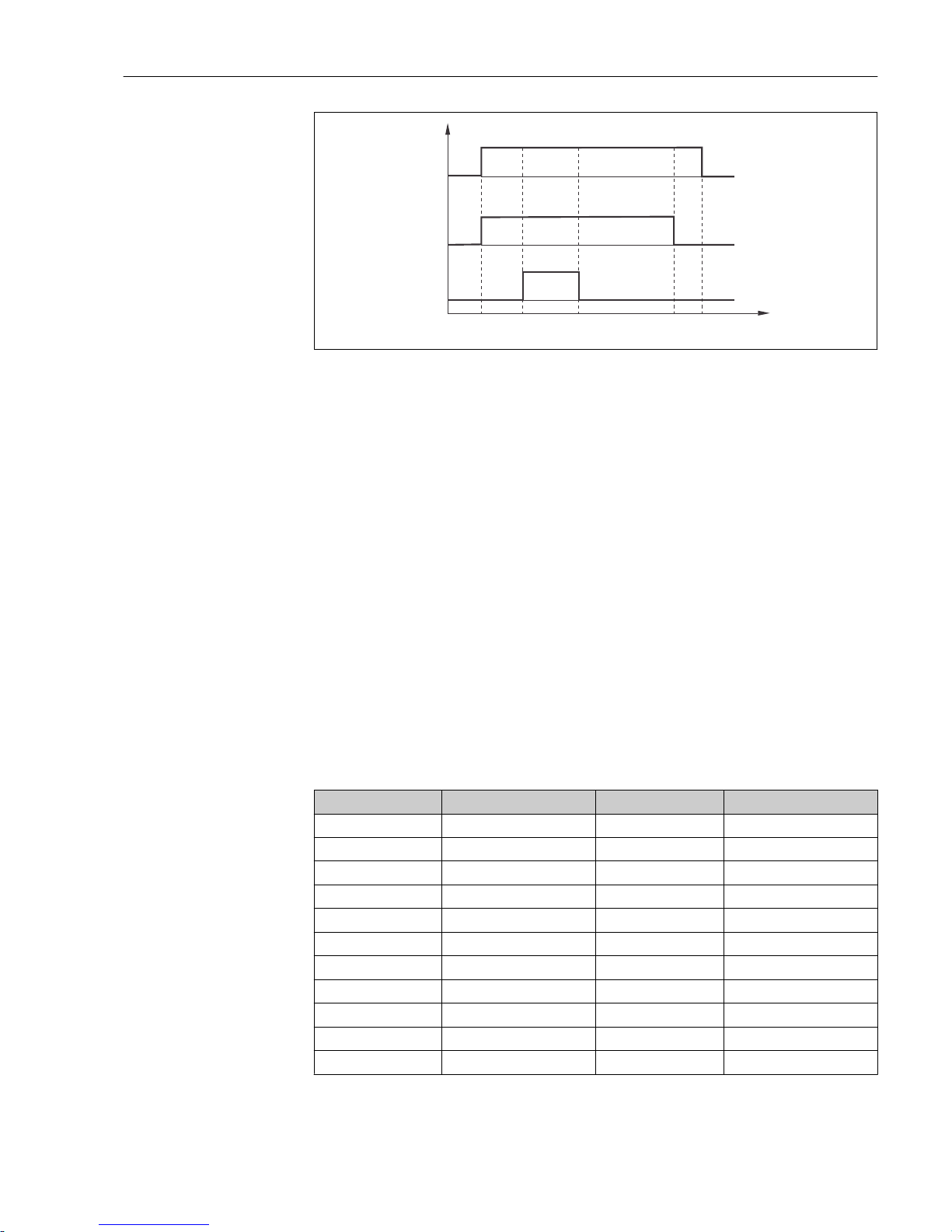
Liquisys M CLM223/253 Commissioning
Endress+Hauser 59
A
B
C
t
0
t
1
t
2
t
3
t
4
t
5
0
0
0
1
1
1
A0025216
35 Sequence of a cleaning cycle
A Hold function
B Water valve is triggered
C Cleaning valve is triggered
0 Contact off
1 Contact on
t0 Normal operation
t1 cleaning start
t2-t1Pre-rinse time
t3-t2Cleaning time
t4-t3Post rinse time
t5-t4Hold dwell period
Limit values for pharmaceutical water according to United States Pharmacopoeia
(USP) and European Pharmacopoeia (EP) (only for conductive sensors)
In the case of conductive sensors, the transmitter has functions for monitoring "Water for
Injection" (WFI), "Highly Purified Water" (HPW) and "Purified Water" (PW) according to the
United States Pharmacopoeia (USP) Part 645 and European Pharmacopoeia (EP)
standards.
USP function: The temperature-dependent limit values in the following table apply for
"Water for Injection" (WFI) according to USP and EP and for "Highly Purified Water" (HPW)
according to EP. The table is programmed into the transmitter.
Temperature [°C] Conductivity [µS/cm] Temperature [°C] Conductivity [µS/cm]
0 0.6 55 2.1
5 0.8 60 2.2
10 0.9 65 2.4
15 1.0 70 2.5
20 1.1 75 2.7
25 1.3 80 2.7
30 1.4 85 2.7
35 1.5 90 2.7
40 1.7 95 2.9
45 1.8 100 3.1
50 1.9
Page 60
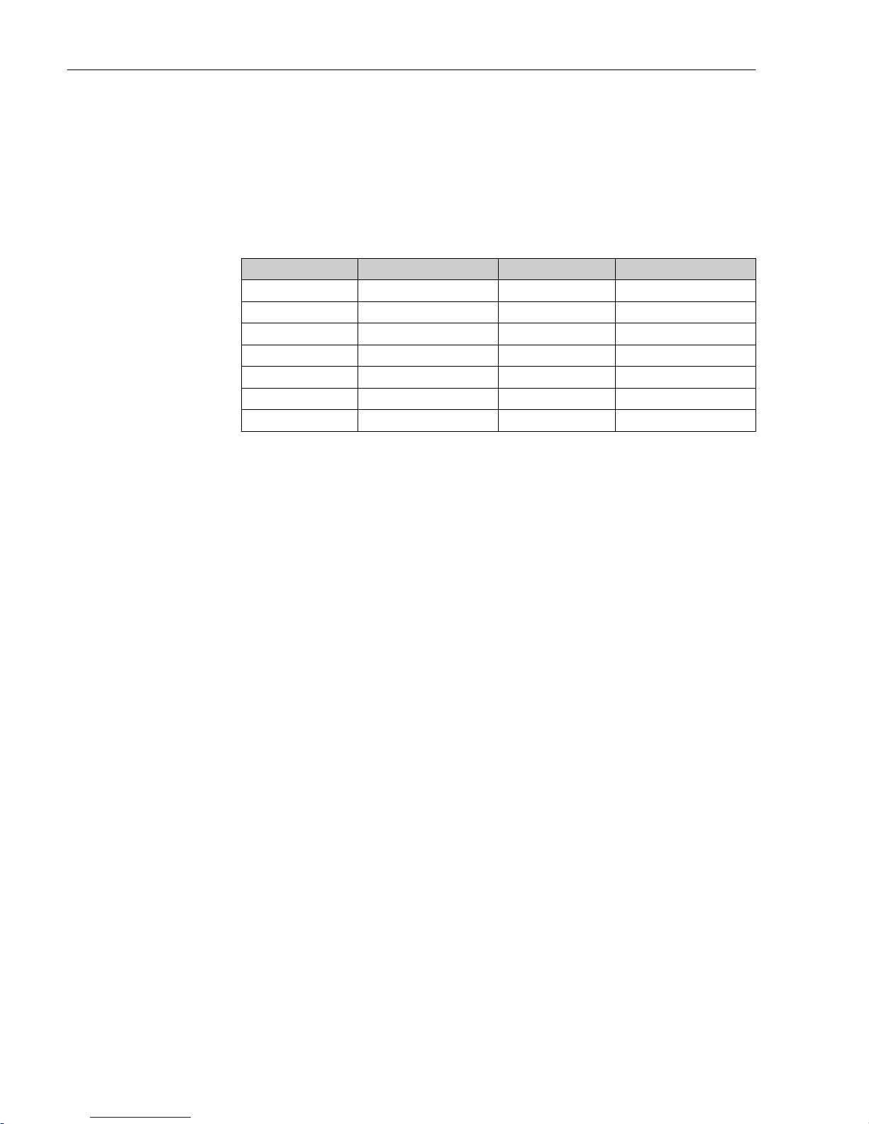
Commissioning Liquisys M CLM223/253
60 Endress+Hauser
The measurement is performed in the following steps:
• The transmitter determines the uncompensated conductivity and the water temperature.
• The transmitter rounds the temperature off to the nearest 5 °C and compares the
measured conductivity with the associated value in the table.
• If the measured value is larger than the value in the table, an alarm is triggered (E151).
EP-PW function: The following table lists the temperature-dependent limit values for
"Purified Water" (PW) in accordance with EP; this table is also programmed into the
transmitter.
Temperature [°C] Conductivity [µS/cm] Temperature [°C] Conductivity [µS/cm]
0 2.4 60 8.1
10 3.6 70 9.1
20 4.3 75 9.7
25 5.1 80 9.7
30 5.4 90 9.7
40 6.5 100 10.2
50 7.1
The measurement is performed in the following steps:
• The transmitter determines the uncompensated conductivity and the water temperature.
• If the temperature is between two table entries, the limit value for the conductivity is
determined by interpolation of the two neighboring points.
• If the measured value is larger than the limit value, an alarm is triggered (E151).
Early warning: A USP early warning is also available. This is activated at a configurable
switch-on point (e.g. 80 % of USP/EP limit value). This means that the user is alerted to be
able to regenerate the plant in time. Der Voralarm wird in Feld R262 bzw. R272
eingestellt.
Please note the following:
• The device must be equipped with a relay card and the Plus Package to be able to use the
USP and EP function.
• To output an alarm, enable the fault-signaling contact or the error current in field F5 F7 (error code E151 and E153).
• The switch-off point of the pre-alarm is 1 % below of the switch-on point (R262 /
R272), related to the main limit value.
• The transmitter also uses the uncompensated values for the USP and EP function when
it displays temperature-compensated values.
• The limit value of 100 °C (212 °F) is used for temperatures over 100 °C (212 °F).
Page 61
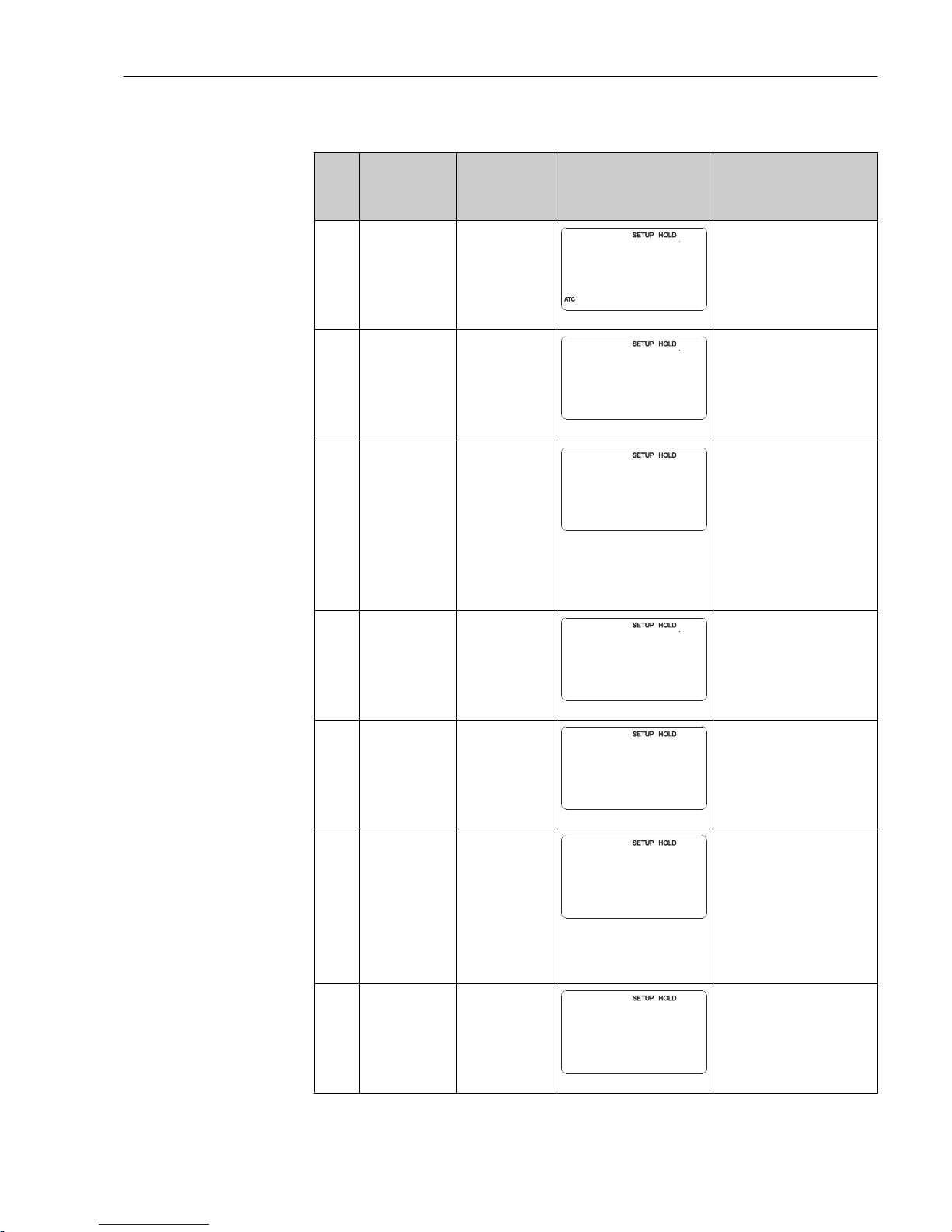
Liquisys M CLM223/253 Commissioning
Endress+Hauser 61
Functions marked in italics are not supported by the basic device version.
Coding Field Range of
adjustment
(factory settings
in bold)
Display Info
R
RELAY
R
RELAIS
A0009058-EN
Relay contact settings
R1 Select the contact
to be configured
Rel1
Rel2
Rel3
Rel4
R1
Sel.Relay
Rel1
A0009059-EN
Rel3 (water) and Rel4
(cleaner) are only available
with the relevant version of
the transmitter.
If Chemoclean is used as the
cleaning method, Rel4 is not
available.
R2 (1) Configure limit
contactor for
conductivity,
resistance or
concentration
measurement
LC PV = limit
contactor
conductivity (1)
LC °C = limit
contactor T (2)
PID controller (3)
Timer (4)
Clean=
Chemoclean (5)
USP (6)
EP PV(7)
R2
Sel.Type
LC PV
A0009060-EN
PV = process value
If Rel4 is selected in the R1
field, Clean = Chemoclean
cannot be selected. By
confirming with ENTER,
another relay function already
switched on is switched off and
its settings are reset to the
factory settings.
R211 Switch function
of R2 (1) off or
on
Off
On
R211
Function
off
A0009067-EN
All the settings are retained.
R212 Enter the switch-
on point of the
contact
Cond/ind: 9999
mS/cm
MOhm: 200
MΩ·cm
Conc: 9999 %
mS/cm
R212
On value
9999
A0009068-EN
Never set the switch-on point
and the switch-off point to the
same value! (Only the
operating mode selected in A1
is displayed.)
R213 Enter the switch-
off point of the
contact
Cond/ind: 9999
mS/cm
MOhm: 200
MΩ·cm
Conc: 9999 %
mS/cm
R213
Off value
9999
A0009069-EN
Entering a switch-off point
selects either a Max contact
(switch-off point < switch-on
point) or a Min contact
(switch-off point > switch-on
point), thereby implementing a
hysteresis that is constantly
required (see "Illustration of
the alarm and limit functions"
figure).
R214 Enter pickup
delay
0 s
0 to 2000 s
s
R214
On Delay
0
A0009070-EN
Page 62
Commissioning Liquisys M CLM223/253
62 Endress+Hauser
Coding Field Range of
adjustment
(factory settings
in bold)
Display Info
R215 Enter dropout
delay
0 s
0 to 2000 s
s
R215
Off Delay
0
A0009071-EN
R216 Enter alarm
threshold
Cond/ind: 9999
mS/cm
MOhm: 200
MΩ·cm
Conc: 9999 %
mS/cm
R216
A.Thresh
9999
A0009072-EN
If the alarm threshold is
undershot/overshot, this
triggers an alarm with the
error message (E067 to E070)
and an error current at the
transmitter (note alarm delay
in field F3).
If defined as a Min contact, the
alarm threshold must be <
switch-off point.
R217 Display status for
limit contactor
MAX
MIN
R217
LC State
MAX
A0009073-EN
Display only
R2 (2) Configure limit
contactor for
temperature
measurement
LC PV = limit
contactor
conductivity (1)
LC °C = limit
contactor T (2)
PID controller (3)
Timer (4)
Clean=
Chemoclean (5)
USP (6)
EP PV(7)
R2
Sel.Type
LC ¡C
A0009061-EN
By confirming with ENTER,
another relay function already
switched on is switched off and
its settings are reset to the
factory settings.
R221 Switch function
of R2 (2) off or
on
Off
On
R221
Function
off
A0009074-EN
R222 Enter switch-on
temperature
250.0 °C
-35.0 to 250.0 °C
R222
C
°
On value
250.0
A0009075-EN
Never set the switch-on point
and the switch-off point to the
same value!
R223 Enter switch-off
temperature
250.0 °C
-35.0 to 250.0 °C
R223
C
°
Off value
250.0
A0009076-EN
Entering a switch-off point
selects either a Max contact
(switch-off point < switch-on
point) or a Min contact
(switch-off point > switch-on
point), thereby implementing a
hysteresis that is constantly
required (see "Illustration of
the alarm and limit functions"
figure).
Page 63
Liquisys M CLM223/253 Commissioning
Endress+Hauser 63
Coding Field Range of
adjustment
(factory settings
in bold)
Display Info
R224 Enter pickup
delay
0 s
0 to 2000 s
R224
s
On Delay
0
A0009077-EN
R225 Enter dropout
delay
0 s
0 to 2000 s
R225
s
Off Delay
0
A0009078-EN
R226 Enter alarm
threshold (as
absolute value)
250.0 °C
-35.0 to 250 °C
R226
C
°
A.Thresh
250.0
A0009079-EN
If the alarm threshold is
undershot/overshot, this
triggers an alarm with the
error message (E067 to E070)
and an error current at the
transmitter (note alarm delay
in field F3).
If defined as a Min contact, the
alarm threshold must be <
switch-off point.
R227 Display status for
limit contactor
MAX
MIN
R227
LC State
MAX
A0009080-EN
Display only
R2 (3) Configure P(ID)
controller
LC PV = limit
contactor
conductivity (1)
LC °C = limit
contactor T (2)
PID controller
(3)
Timer (4)
Clean=
Chemoclean (5)
USP (6)
EP PV(7)
R2
Sel.Type
PID
A0009062-EN
By confirming with ENTER,
another relay function already
switched on is switched off and
its settings are reset to the
factory settings.
R231 Switch function
of R2 (3) off or
on
Off
On
Basic
PID+B
R231
Function
off
A0009081-EN
On = PID controller
Basic = basic load dosing
PID+B = PID controller + basic
load dosing
R232 Enter set point Cond/ind: 0.00
μS/cm
MOhm: 0.00
kΩ·cm
Conc: 0.00 %
µS/cm
R232
Setpoint
0.00
A0009084-EN
The set point is the value to be
maintained by the control
system. Using this control
process, this value is restored
when an upwards or
downwards deviation occurs.
Page 64
Commissioning Liquisys M CLM223/253
64 Endress+Hauser
Coding Field Range of
adjustment
(factory settings
in bold)
Display Info
R233 Enter control
gain K
P
1.00
0.01 to 20.00
R233
Kp
1.00
A0009085-EN
See the "P(ID) controller"
section.
R234 Enter integral
action time T
n
(0.0 = no Icomponent)
0.0 min
0.0 to 999.9 min
R234
min
Time Tn
0.0
A0009086-EN
See the "P(ID) controller"
section.
With every hold, the Icomponent is set to zero.
Although the hold can be
deactivated in field S2, this
does not apply for Chemoclean
and timer!
R235 Enter derivative
action time T
v
(0.0 = no Dcomponent)
0.0 min
0.0 to 999.9 min
R235
min
Time Tv
0.0
A0009087-EN
See the "P(ID) controller"
section.
R236 Select controller
characteristic
Dir = direct
Inv = inverse
R236
Direction
dir
A0009088-EN
The setting is required
depending on the control
deviation (upward or
downward deviation, see the
"P(ID) controller" section).
R237 Select pulse
length or pulse
frequency
Len = pulse
length
Freq = pulse
frequency
Curr = current
output 2
R237
Oper.Mode
len
A0009089-EN
Pulse length e.g. for solenoid
valve, pulse frequency e.g. for
solenoid dosing pump, see the
"Actuating signal outputs"
section.
Curr = current output 2 can
only be selected if O2 = Contr.
R238 Enter pulse
interval
10.0 s
0.5 to 999.9 s
R238
s
PulsePer.
10.0
A0009090-EN
This field only appears if pulse
length is selected in R237.
If pulse frequency is selected,
R238 is skipped and entries
continue with R239.
R239 Enter maximum
pulse frequency
of the adjuster
120 min
-1
60 to 180 min
-1
R239
1/min
Max.PFreq
120
A0009091-EN
This field only appears if pulse
frequency is selected in R237.
If pulse length is selected,
R239 is skipped and entries
continue with R2310.
R2310 Enter minimum
switch-on time
t
ON
0.3 s
0.1 to 5.0 s
R2310
s
Min.PTime
0.3
A0009082-EN
This field only appears if pulse
length is selected in R237.
Page 65
Liquisys M CLM223/253 Commissioning
Endress+Hauser 65
Coding Field Range of
adjustment
(factory settings
in bold)
Display Info
R2311 Enter basic load 0 %
0 to 40 %
R2311
%
BasicLoad
0
A0009083-EN
When you select the basic load,
you enter the desired dosing
quantity.
100% basic load would
correspond to:
• Constantly on if R237 = len
• Fmax if R237 = freq (field
R239)
• 20 mA if R237 = curr
R2 (4) Configure
cleaning function
(timer)
LC PV = limit
contactor
conductivity (1)
LC °C = limit
contactor T (2)
PID controller (3)
Timer (4)
Clean=
Chemoclean (5)
USP (6)
EP PV(7)
R2
Sel.Type
Timer
A0009063-EN
Only one cleaning agent
(generally water) is used for
the cleaning.
By confirming with ENTER,
another relay function already
switched on is switched off and
its settings are reset to the
factory settings.
R241 Switch function
of R2 (4) off or
on
Off
On
R241
Function
off
A0009092-EN
R242 Enter rinsing/
cleaning time
30 s
0 to 999 s
R242
s
RinseTime
30
A0009093-EN
Settings for hold and relay are
active for this time.
R243 Enter pause time 360 min
1 to 7200 min
R243
min
PauseTime
360
A0009094-EN
The pause time is the time
between two cleaning cycles
(see the "Timer for cleaning
function" section).
R244 Enter minimum
pause time
120 min
1 to R243
R244
min
Min.Pause
120
A0009095-EN
The minimum pause time
prevents constant cleaning if a
cleaning trigger is pending.
R2 (5) Configure
cleaning with
Chemoclean (for
version with four
contacts,
Chemoclean
option and
contacts 3 and 4
assigned)
LC PV = limit
contactor
conductivity (1)
LC °C = limit
contactor T (2)
PID controller (3)
Timer (4)
Clean=
Chemoclean (5)
USP (6)
EP PV(7)
R2
Sel.Type
Clean
A0009064-EN
See the "Chemoclean function"
section.
By confirming with ENTER,
another relay function already
switched on is switched off and
its settings are reset to the
factory settings.
Page 66
Commissioning Liquisys M CLM223/253
66 Endress+Hauser
Coding Field Range of
adjustment
(factory settings
in bold)
Display Info
R251 Switch function
of R2 (5) off or
on
Off
On
R251
Function
off
A0009096-EN
R252 Select type of
start pulse
Int = internal
(timecontrolled)
Ext = external
(digital input 2)
I+ext = internal +
external
I+stp = internal,
suppressed by
external
R252
CleanTrig
int
A0009097-EN
The cycle for the "int" function
is started when the pause time
ends (R257).
No real time clock is available.
External suppression is
required for irregular time
intervals (e.g. weekends).
R253 Enter pre-rinse
time
20 s
0 to 999 s
R253
s
PreRinse
20
A0009098-EN
Rinsing is performed with
water.
R254 Enter cleaning
time
10 s
0 to 999 s
R254
s
CleanTime
10
A0009099-EN
Cleaning is performed with
cleaning agent and water.
R255 Enter post rinse
time
20 s
0 to 999 s
R255
s
PostRinse
20
A0009100-EN
Rinsing is performed with
water.
R256 Enter number of
repeat cycles
0
0 to 5
R256
Rep.Rate
0
A0009101-EN
R253 to R255 is repeated.
R257 Enter pause time 360 min
1 to 7200 min
R257
min
PauseTime
360
A0009102-EN
The pause time is the time
between two cleaning cycles
(see the "Chemoclean function"
section).
R258 Enter minimum
pause time
120 min
1 to R257
R258
min
Min.Pause
120
A0009103-EN
The minimum pause time
prevents constant cleaning if
an external cleaning start is
pending.
Page 67
Liquisys M CLM223/253 Commissioning
Endress+Hauser 67
Coding Field Range of
adjustment
(factory settings
in bold)
Display Info
R259 Enter number of
cleaning cycles
without cleaning
agent (economy
function)
0
0 to 9
R259
EconomyCl
0
A0009104-EN
After cleaning with cleaner, up
to 9 cleaning sessions can be
carried out with water only
until the next cleaning session
with cleaner takes place.
R2 (6) Configure USP
contact (only for
Plus Package
with relay card)
LC PV = limit
contactor
conductivity (1)
LC °C = limit
contactor T (2)
PID controller (3)
Timer (4)
Clean=
Chemoclean (5)
USP (6)
EP PV(7)
R2
Sel.Type
USP
A0009065-EN
The USP contact can be
configured as an early warning
alarm, i.e. it alerts the user
before the actual limit value is
reached.
Error no. E151 appears in the
event of an alarm.
WFI according to USP; HPW
according to EP
R261 Switch function
of R2 (6) off or
on
Off
On
R261
Function
Off
A0009105-EN
R262 Early warning
threshold: enter
switch-on point
80.0 %
0.0 to 100.0 %
R262
%
On Value
80.0
A0009106-EN
The early warning triggers the
contact.
When the alarm value is
reached (100%), the alarm
relay is also triggered.
Example: Given 15 °C and 1.0
μS/cm, a USP early warning
alarm is triggered at 0.8 μS/cm
when the setting is 80%.
R264 Early warning
threshold: enter
pickup delay
0 s
0 to 2000 s
R264
s
On Delay
0
A0009107-EN
R265 Early warning
threshold: enter
dropout delay
0 s
0 to 2000 s
R265
s
Off Delay
0
A0009108-EN
R2 (7) Configure EP PV
contact (only for
Plus Package
with relay card)
LC PV = limit
contactor
conductivity (1)
LC °C = limit
contactor T (2)
PID controller (3)
Timer (4)
Clean=
Chemoclean (5)
USP (6)
EP PV(7)
R2
Sel.Type
EP PW
A0009066-EN
The EP PV contact can be
configured as an early warning
alarm, i.e. it alerts the user
before the actual limit value is
reached.
Error no. E151 appears in the
event of an alarm.
PV according to EP
Page 68
Commissioning Liquisys M CLM223/253
68 Endress+Hauser
Coding Field Range of
adjustment
(factory settings
in bold)
Display Info
R271 Switch function
of R2 (7) off or
on
Off
On
R271
Function
Off
A0009109-EN
R272 Early warning
threshold: enter
switch-on point
80.0 %
0.0 to 100.0 %
R272
%
On Value
80.0
A0009110-EN
The early warning triggers the
contact.
When the alarm value is
reached (100%), the alarm
relay is also triggered.
Example: Given 15 °C and 1.0
μS/cm, an EP PV early warning
alarm is triggered at 0.8 μS/cm
when the setting is 80%.
R274 Early warning
threshold: enter
pickup delay
0 s
0 to 2000 s
R274
s
On Delay
0
A0009111-EN
R275 Early warning
threshold: enter
dropout delay
0 s
0 to 2000 s
R275
s
Off Delay
0
A0009112-EN
Page 69
Liquisys M CLM223/253 Commissioning
Endress+Hauser 69
7.4.8 Temperature compensation with table
The "ALPHA TABLE" function group is not available in the basic device version. You require
the Plus Package to access this function group. With this function group, you can perform
temperature compensation using a table (field B2).
Enter the α-T value pairs (see SETUP 2) in the T4 and T5 fields.
Functions marked in italics are not supported by the basic device version.
Coding Field Range of
adjustment
(factory
settings in bold)
Display Info
T
ALPHA TABLE
function group
T
ALPHA TAB
A0009123-EN
Settings for temperature
compensation.
T1 Select table
option
Read
Edit
T1
Sel.Table
read
A0009125-EN
T2 Enter number of
table value pairs11 to 10
T2
No. Elem.
1
A0009126-EN
In the α-table, you can enter a
maximum of 10 value pairs.
These pairs are saved under
numbers 1 to 10 and can be
changed individually or
consecutively.
T3 Select table
value pair
1
1 to number of
table value pairs
Assign
T3
Sel.Elem.
1
A0009127-EN
The system automatically runs
through the T3 to T5 function
chain as often as corresponds to
the value indicated in T2.
"Assign" appears as the last
value.
The display goes to T6 once the
process is finished.
T4 Enter
temperature
value
0.0 °C
-35.0 to 250.0 °C
T4
C
°
Temp.val.
0.0
A0009128-EN
The temperature values must be
at least 1 K apart.
Factory setting for the
temperature value in the table
value pairs:
0.0 °C; 10.0 °C; 20.0 °C; 30.0 °C ...
T5 Enter
temperature
coefficient α
2.10 %/K
0.00 to 20.00
%/K
T5
%/K
alpha val
2.10
A0009129-EN
T6 Message as to
whether table
status is OK
Yes
No
T6
Status ok
yes
A0009130-EN
Display only
If status = "no", you must set
correct values in the table (all
settings made up until now
remain intact) or go back to the
measuring mode (then the table
is not valid).
Page 70
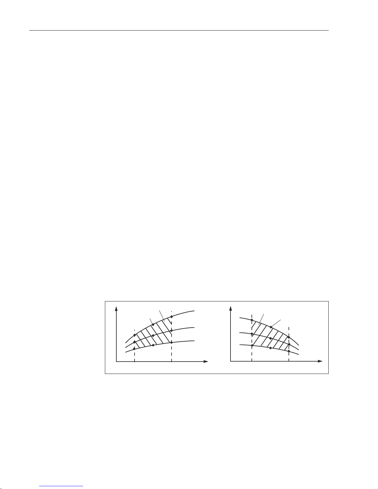
Commissioning Liquisys M CLM223/253
70 Endress+Hauser
7.4.9 Concentration Measurement
The CONCENTRATION function group is only available for devices with a Plus Package.
The transmitter can convert from conductivity values to concentration values. For this
purpose, the operating mode is first set to concentration measurement (see field A1).
Afterwards, in the measuring device you must specify the basic data on the basis of which
the concentration is to be calculated. You require the conductivity characteristic curves of
the medium for this.
In the case of conductive sensors, the effects of polarization in the boundary layer between
the sensor and medium restrict the measuring range. The transmitter can detect
polarization effects by using a smart signal analysis process. Error message E071 is
displayed.
You can either refer to your data sheets for these characteristic curves or determine the
characteristic curves yourself.
1. Create samples of the medium in the concentrations that occur in the process.
2. Then measure the uncompensated conductivity of these samples at temperatures that
also occur in the process.
• For variable process temperatures:
If variable process temperatures are to be taken into consideration, you must
measure the conductivity for at least two temperatures (ideally the minimum and
maximum process temperature) for the samples created. The temperature values of
the various samples must be identical in each case. The temperatures must be at
least 0.5 °C apart.
At least two samples of different concentrations, taken at two different
temperatures in each case, are required as the transmitter needs at least four points
in the table (this must include the minimum and maximum concentration values).
• For constant process temperatures:
Measure the differently concentrated samples at this temperature. At least two
samples are required.
At the end you should have measuring data which resemble those shown in the following
figures.
k
k
C CC
min
C
min
T
1
T
1
T
2
T
2
T
3
T
3
C
max
C
max
2
2
1
1
A0008926
36 Example of measured data for variable temperatures
κ Conductivity
C Concentration
T Temperature
1 Measuring point
2 Measuring range
Page 71
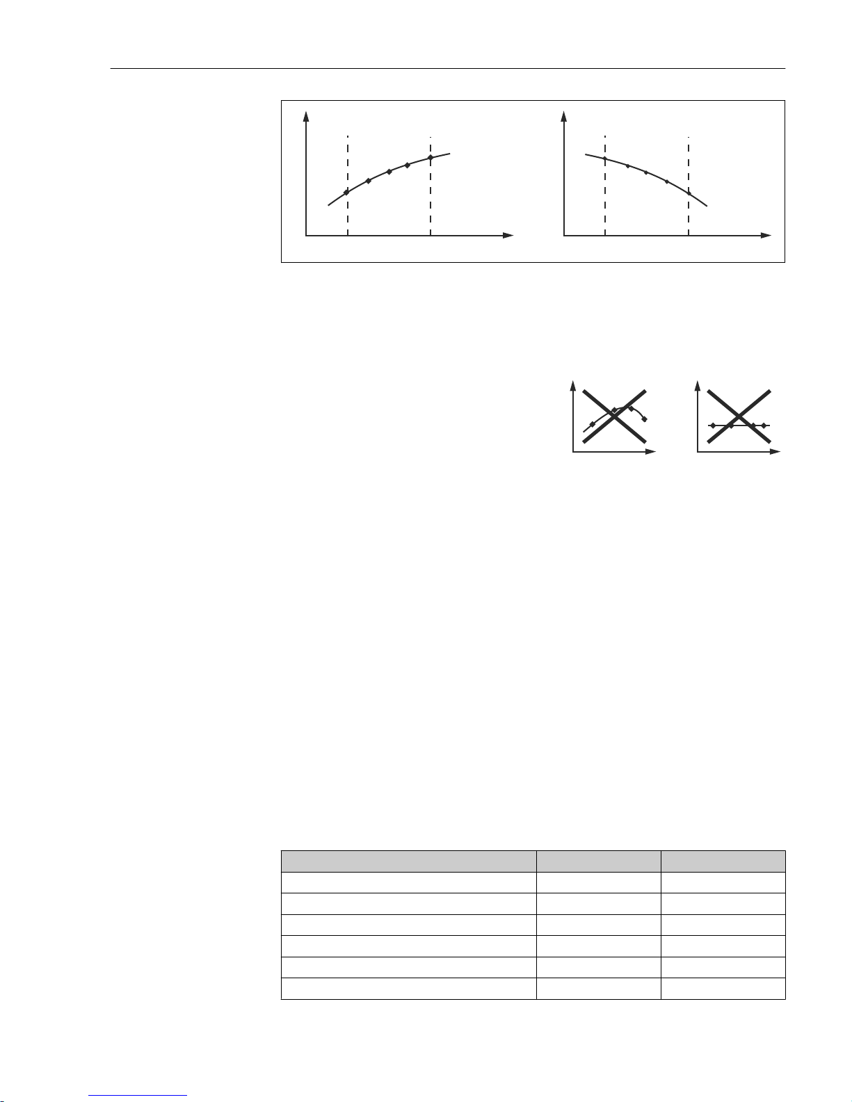
Liquisys M CLM223/253 Commissioning
Endress+Hauser 71
k
C
1
T
C
min
C
max
k
C
1
T
C
min
C
max
A0008925
37 Example of measured data for constant temperatures
κ Conductivity
C Concentration
T Constant temperature
1 Measuring range
The characteristic curves received from the measuring
points must increase or decrease very monotonically in
the range of the process conditions, i.e. neither
maximum points, nor minimum points, nor ranges
with a constant behavior can occur. The curve profiles
opposite are therefore not permitted.
k
C
C
k
A0008927
38 Impermissible curve profiles
κ Conductivity
C Concentration
Value entry
Enter the three characteristic values for each measured sample in the fields K6 to K8
(value triplets of uncompensated conductivity, temperature and concentration).
• Variable process temperature:
Enter at least the four value triplets needed.
• Constant process temperature:
Enter at least the two value triplets needed.
Please note the following:
If the measured values of the process are outside the range of your sample values, this
considerably reduces the level of accuracy and the error message E078 or E079 will be
displayed. Therefore, take the limit values of your process into consideration when
determining the characteristic curves. Wird bei aufsteigender
If you enter an additional value triplet of 0 μS/cm and 0% for every temperature used
when the characteristic curve is increasing, you can work from the start of the measuring
range with sufficient accuracy and without an error message.
Enter the values in order of increasing concentration (see the following example).
mS/cm % °C
240 96 60
380 96 90
220 97 60
340 97 90
120 99 60
200 99 90
Page 72
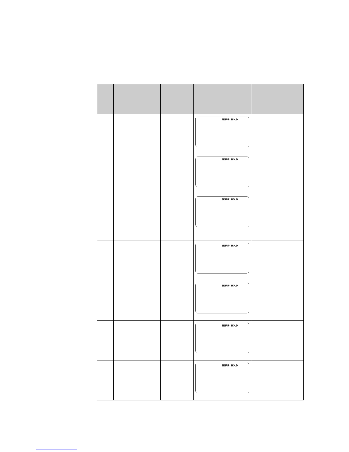
Commissioning Liquisys M CLM223/253
72 Endress+Hauser
As the temperature is already processed in the concentration tables, the settings for
temperature compensation in the Setup 2 menu (fields B2 and B3) are ineffectual for
concentration measurement.
Functions marked in italics are not supported by the basic device version.
Coding Field Range of
adjustment
(factory
settings in
bold)
Display Info
K
CONCENTRATION
function group
K
CONCENTRA
A0009113-EN
Four different
concentration fields can be
entered in this function
group.
K1 Select the active
concentration curve on
which the calculation of
the display value is
based
1
1 to 4
K1
act.curve
1
A0009114-EN
The curves are
independent of one
another. Four different
curves can be defined.
K2 Select the curve to be
edited
1
1 to 4
K2
editCurve
1
A0009115-EN
If a curve is being edited,
another curve should be
used to calculate the
current display values.
Example: If curve 2 is
being edited, either curve
1, curve 3 or curve 4
should be active (see K1).
K3 Select table option Read
Edit
K3
Table
read
A0009116-EN
This option is valid for all
concentration curves.
K4 Enter number of
reference triplets
1
1 to 10
K4
No. Elem.
1
A0009117-EN
Each triplet consists of
three numeric values.
K5 Select triplet 1
1 to number of
triplets in K4
Assign
K5
Sel.Elem.
1
A0009118-EN
Any triplet can be edited.
"Assign" takes the user to
K9
K6 Enter uncompensated
conductivity value
0.0 mS/cm
0.0 to 9999
mS/cm
K6
mS/cm
conduct.
0.0
A0009119-EN
The system automatically
runs through the K5 to K6
function chain as often as
corresponds to the value
indicated in K4. The
display then goes to K9.
Page 73
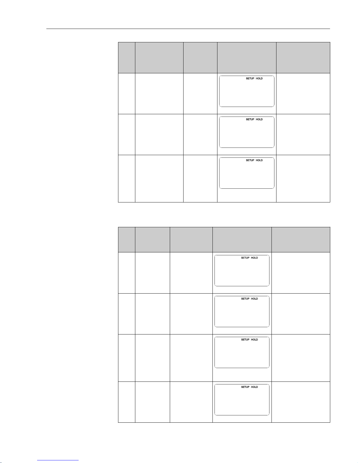
Liquisys M CLM223/253 Commissioning
Endress+Hauser 73
Coding Field Range of
adjustment
(factory
settings in
bold)
Display Info
K7 Enter concentration
value for K6
0.00 %
0.00 to 99.99 %
K7
%
concentr.
0.00
A0009120-EN
Engineering unit as
selected in A2.
Format as selected in A3.
K8 Enter temperature value
for K6
0.0 °C
-35.0 to 250.0
°C
K8
C
°
Temp.val.
0.0
A0009121-EN
K9 Message as to whether
table status is OK
Yes
No
K9
Status ok
yes
A0009122-EN
Read only.
If "No", then set correct
values in the table (all
settings made up until
now remain intact) or go
back to the measuring
mode (then the table is
not valid).
7.4.10 Service
Coding Field Range of
adjustment
(factory settings in
bold)
Display Info
S
SERVICE
function group
S
SERVICE
A0008408-EN
Service function settings.
S1 Select language ENG = English
GER = German
FRA = French
ITA = Italian
NL = Dutch
ESP = Spanish
S1
Language
ENG
A0008409-EN
The option selected only
applies for the faultsignaling contact, not for the
error current.
S2 Configure a hold S+C = hold during
configuration and
calibration
Cal = hold during
calibration
Setup = hold during
configuration
None = no hold
S2
Auto HOLD
S+C
A0008413-EN
S = setup
C = calibration
S3 Manual hold Off
On
S3
Man. HOLD
off
A0008414-EN
The setting is retained even
in the event of a power
failure.
Page 74
Commissioning Liquisys M CLM223/253
74 Endress+Hauser
Coding Field Range of
adjustment
(factory settings in
bold)
Display Info
S4 Enter hold dwell
period
10 s
0 to 999 s
S4
s
Cont.Time
10
A0008415-EN
S5 Enter SW
upgrade release
code (Plus
Package)
0000
0000 to 9999
S5
0000
PlusCode
A0008416-EN
The code can be found on the
nameplate.
If an incorrect code is
entered, you are taken back
to the measurement menu.
The number is edited with
the PLUS or MINUS key and
confirmed with the ENTER
key. "1" is displayed if the
code is active.
S6 Enter SW
upgrade release
code for
Chemoclean
0000
0000 to 9999
S6
CleanCode
0000
A0008417-EN
The code can be found on the
nameplate.
If an incorrect code is
entered, you are taken back
to the measurement menu.
The number is edited with
the PLUS or MINUS key and
confirmed with the ENTER
key. "1" is displayed if the
code is active.
S7 Order number is
displayed
S7
PR0005
order
A0008418-EN
If the device is upgraded, the
order code is changed
automatically.
S8 Serial number is
displayed
S8
12345678
SerNo
A0008420-EN
S9 Reset the device
to the basic
settings
No
Sens = sensor data
Facty = factory
settings
S9
S.Default
no
A0008421-EN
Sens = last calibration is
deleted and is reset to factory
setting.
Facty = all data (apart from
A1 and S1) are deleted and
reset to the factory setting!
S10 Perform device
test
No
Displ = display test
S10
Test
no
A0008410-EN
Page 75
Liquisys M CLM223/253 Commissioning
Endress+Hauser 75
7.4.11 E+H Service
Coding Field Range of adjustment
(factory settings in
bold)
Display Info
E
E+H SERVICE
function group
E
E+H SERV
A0007857-EN
Information on the
device version
E1 Select module Contr = controller
(central module) (1)
Trans = transmitter (2)
Main = power unit (3)
Rel = relay module (4)
Sens = sensor (5)
E1
Select
Contr
A0007858-EN
E111
E121
E131
E141
E151
Software version is
displayed
E111
SW-Vers.
xx.xx
A0007859-EN
If E1 = contr: device
software
If E1 = trans, main, rel:
module firmware
If E1 = sens: sensor
software
E112
E122
E132
E142
E152
Hardware version
is displayed
E112
HW-Vers.
xx.xx
A0007861-EN
Info display
E113
E123
E133
E143
E153
Serial number is
displayed
E113
12345678
SerNo
A0007860-EN
Info display
E114
E124
E134
E144
E154
Module ID is
displayed
E114
Modul-ID
LSG
A0007862-EN
Info display
Page 76
Commissioning Liquisys M CLM223/253
76 Endress+Hauser
7.4.12 Interfaces
Coding Field Range of
adjustment
(factory settings
in bold)
Display Info
I
INTERFACE
function group
I
INTERFACE
A0007863-EN
Communication settings (only
for HART or PROFIBUS device
version).
I1 Enter bus
address
Address
HART: 0 to 15
or
PROFIBUS: 0 to
126
I1
Address
126126
A0007864-EN
Each address may only be
assigned once in a network. If a
device address ≠ 0 is selected for
a HART device, the current
output is automatically set to 4
mA and the device prepares for
multi-drop operation.
I2 The tag name is
displayed
I2
@@@@@@@@
Tag
A0007865-EN
7.4.13 Communication
For devices with a communication interface, please also refer to the separate Operating
Instructions BA00208C/07/EN (HART®) or BA00209C/07/DE (PROFIBUS®).
Page 77
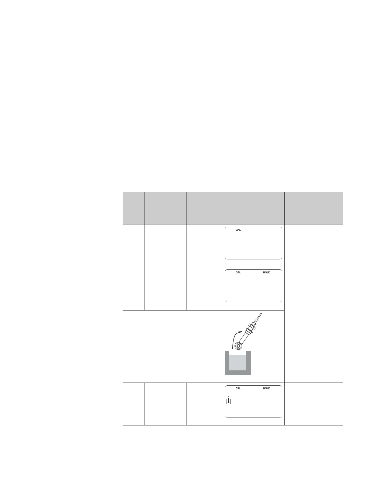
Liquisys M CLM223/253 Commissioning
Endress+Hauser 77
7.5 Calibration
Use the CAL key to access the calibration function group.
Use this function group to calibrate and adjust the transmitter. The calibration can be
performed in two different ways:
• By measuring in a calibration solution of known conductivity.
• By entering the exact cell constant of the conductivity sensor.
Please note the following:
• During initial commissioning of inductive sensors, an air set is absolutely essential for
residual coupling compensation (from field C111) so that the measuring system can
return precise measurement data.
• If the calibration procedure is aborted by pressing the PLUS and MINUS keys at the same
time (return to C114, C126 or C136) or if the calibration is faulty, then the previous
calibration data are reinstated. A calibration error is indicated by “ERR” and the sensor
symbol flashes on the display.
Repeat calibration!
• For each calibration, the device automatically switches to hold (factory setting).
• On completion of the calibration, the device returns to the measurement mode. The
"hold" symbol appears on the display during the hold dwell period (field S4).
• Only items C121 to C126 are relevant for conductive sensors.
Coding Field Range of
adjustment
(factory
settings in
bold)
Display Info
C
CALIBRATION
function group:
C
CALIBRAT
A0009141-EN
Airs and InstF do not apply
for conductive
measurement.
C1(1) Calibration of
inductive sensors
with annular
opening
Airs = air set
(1)
Cellc = cell
constant (2)
InstF =
installation
factor (3)
C1
Calibrat
AirS
A0009142-EN
When commissioning
inductive sensors, an air set
is mandatory. The sensor
air set must be performed in
air and in a dry state.
Take the inductive sensor out of the liquid and
dry it fully.
A0025597
C111 Residual coupling
start calibration
(air set)
Current
measured value
C111
µS/cm
AirSet
0.0
A0009145-EN
Press CAL to start the
calibration.
Page 78
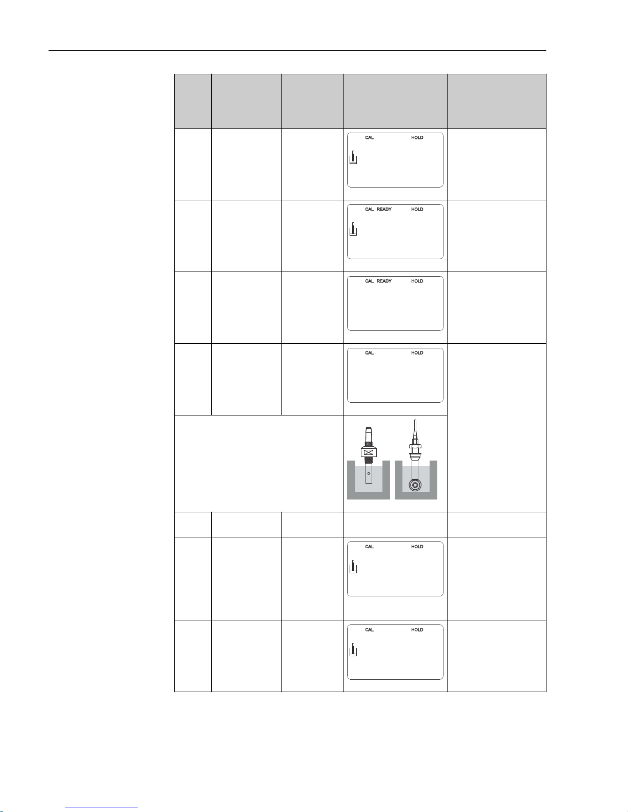
Commissioning Liquisys M CLM223/253
78 Endress+Hauser
Coding Field Range of
adjustment
(factory
settings in
bold)
Display Info
C112 The residual
coupling is
displayed (air set)
-80.0 to 80.0
μS/cm
C112
µS/cm
AirSetVal
5.3
A0009146-EN
Residual coupling of
measuring system (sensor
and transmitter).
C113 Calibration status
is displayed
o.k.
E xxx
C113
Status
o.k.
A0009147-EN
If the calibration status is
not o.k., a reason for the
error is provided on the
second line of the display.
C114 Store calibration
result?
Yes
No
New
C114
Store
yes
A0009148-EN
If C113 = E xxx, then only
No or New.
If New, return to C.
If Yes/No, return to
"Measurement".
C1(2) Cell constant
calibration
Airs = air set (1)
Cellc = cell
constant (2)
InstF =
installation
factor (3)
C1
Calibrat
Cellc
A0009143-EN
The sensor should be
immersed in such a way
that there is sufficient
distance to the vessel wall
(the installation factor has
no influence if a > 15 mm).
Immerse the sensor in the calibration solution.
The following section describes calibration
with the temperature-compensated
conductivity value of the reference solution.
If calibration is to be performed with the
uncompensated conductivity value, you
must set the temperature coefficient α to
zero.
A0025598
C121 Enter calibration
temperature (MTC)
25 °C
-35.0 to 250.0 °C
Only available if B1 = fixed.
C122 Enter the α value
of the calibration
solution
2.10 %/K
0.00 to 20.00
%/K
%/K
C122
alpha val
2.10
A0009150-EN
The value is given in the
Technical Information for
all E+H calibration
solutions. You can also use
the printed-on table to
calculate the value.
Set α to 0 for calibration
with uncompensated values.
C123 Enter the correct
conductivity value
of the calibration
solution
Current
measured value
0.0 μS/cm to
9999 mS/cm
C123
mS/cm
Real. val
10.30
A0009151-EN
A value close to the
subsequent operating range
should be selected.
Page 79
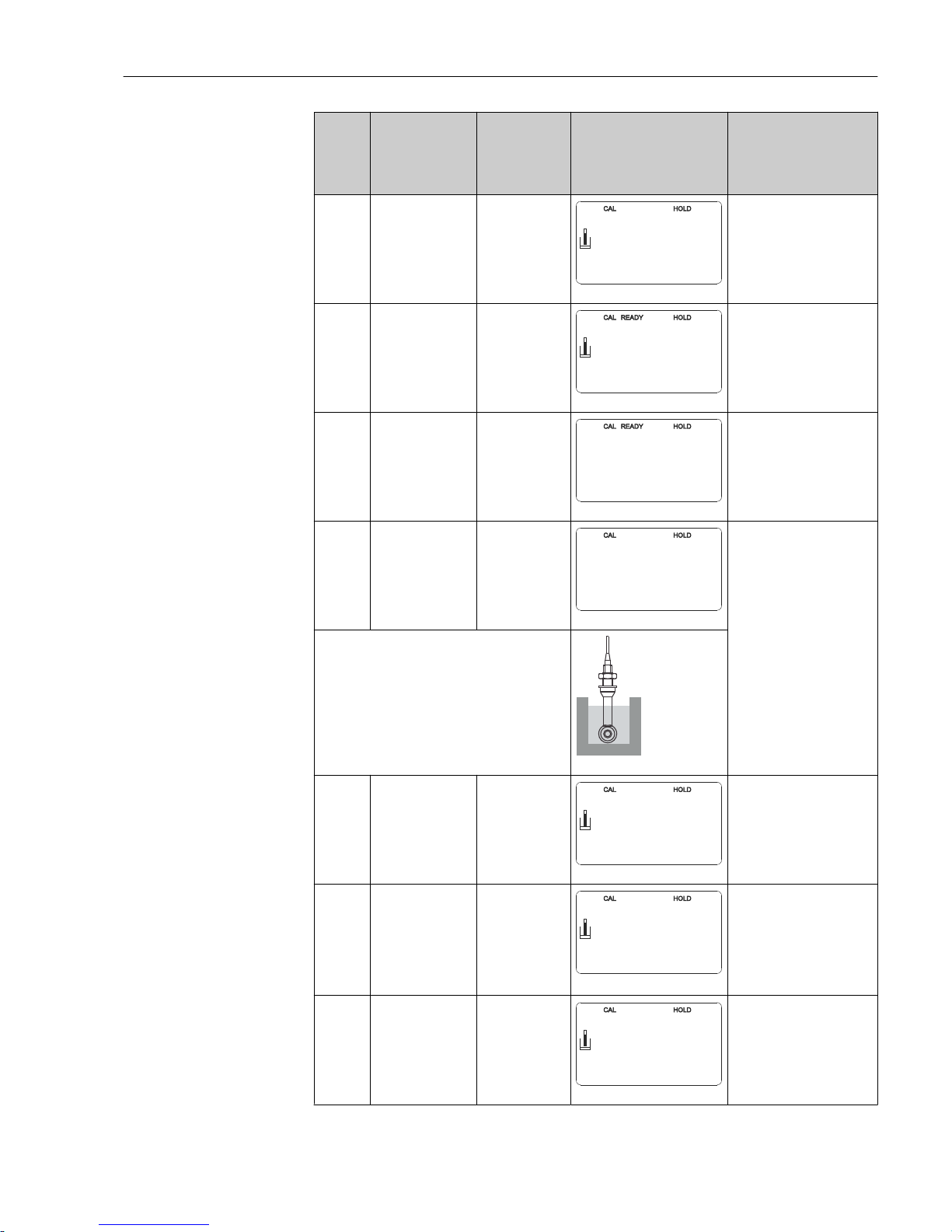
Liquisys M CLM223/253 Commissioning
Endress+Hauser 79
Coding Field Range of
adjustment
(factory
settings in
bold)
Display Info
C124 The calculated cell
constant is
displayed
0.0025 to 99.99
cm
-1
C124
1/cm
Cellconst
1.000
A0009152-EN
The calculated cell constant
is displayed and accepted in
A5.
C125 Calibration status
is displayed
o.k.
E xxx
C125
Status
o.k.
A0009153-EN
If the calibration status is
not o.k., a reason for the
error is provided on the
second line of the display.
C126 Store calibration
result?
Yes
No
New
C126
Store
yes
A0009154-EN
If C125 = E xxx, then only
No or New.
If New, return to C.
If Yes/No, return to
"Measurement".
C1(3) Calibration with
sensor adjustment
for inductive
sensors (only for
Plus Package)
Airs = air set (1)
Cellc = cell
constant (2)
InstF =
installation
factor (3)
C1
Calibrat
InstF
A0009144-EN
Sensor adjustment with
compensation for wall
effects.
In the case of inductive
sensors, the measured value
is influenced by the distance
between the sensor and the
pipe wall and by the
material of the pipe
(conductive or insulating).
The installation factor
indicates these
dependencies. See the
Technical Information of
the sensor used for more
information
The inductive sensor is mounted at the place of
installation.
A0025599
C131 Enter the process
temperature (MTC)
25 °C
-35.0 to 250.0 °C
C131
C
°
MTC temp.
25.0
A0009155-EN
Only available if B1 = fixed.
C132 Enter the α value of
the calibration
solution
2.10 %/K
0.00 to 20.00
%/K
C132
%/K
alpha val
2.10
A0009156-EN
The value is given in the TI
for all E+H calibration
solutions. You can also use
the printed-on table to
calculate the value.
Set α to 0 for calibration
with uncompensated values.
C133 Enter the correct
conductivity value
of the calibration
solution
Current
measured value
0.0 μS/cm to
9999 mS/cm
C133
mS/cm
Real val.
10.30
A0009157-EN
A value close to the
subsequent operating range
should be selected.
Page 80
Commissioning Liquisys M CLM223/253
80 Endress+Hauser
Coding Field Range of
adjustment
(factory
settings in
bold)
Display Info
C134 Calculated
installation factor
is displayed
1
0.10 to 5.00
C134
InstFact
1
A0009158-EN
The installation factor
indicates the dependency
between the measured
value and the distance
between the sensor and
pipe wall. See the Technical
Information of the sensor
used for more information.
C135 Calibration status is
displayed
o.k.
E xxx
C135
Status
o.k.
A0009159-EN
If the calibration status is
not o.k., a reason for the
error is provided on the
second line of the display.
C136 Store calibration
result?
Yes
No
New
C136
Store
yes
A0009160-EN
If C135 = E xxx, then only
No or New.
If New, return to C.
If Yes/No, return to
"Measurement".
Page 81
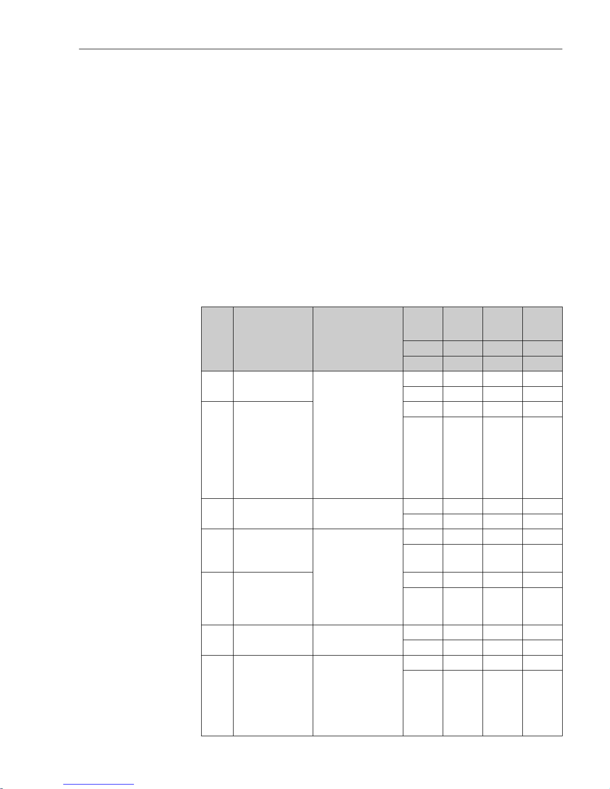
Liquisys M CLM223/253 Diagnostics and troubleshooting
Endress+Hauser 81
8 Diagnostics and troubleshooting
8.1 Trouble shooting instructions
The transmitter continuously monitors its functions itself. If an error occurs which the
device recognizes, this is indicated on the display. The error number is shown below the
display of the main measured value. If more than one error occurs, you can call these up
with the MINUS key.
Refer to the "System error messages" table for the possible error numbers and remedial
measures.
Should a malfunction occur without any transmitter error message, please refer to the
"Process-specific errors" or the "Device-specific errors" tables to localize and rectify the error.
These tables provide you with additional information on any spare parts required.
8.2 System error messages
You can display and select the error messages with the MINUS key.
Error
No.
Display Tests/remedial action Alarm
contact
Error
current
Autom.
cleaning
start
PROFIBU
S
Status
Facty Facty Facty PV
1)
User User User Temp
E001 EEPROM memory
error
• Switch off device and
switch it on again.
• Load software
compatible with
hardware
• Load measurementparameter specific
device software.
• If the error persists,
send in the device for
repair to your local
sales center or replace
the device.
Yes No X 0C
X 0C
E002 Device not calibrated,
calibration data
invalid, no user data or
user data invalid
(EEPROM error),
device software not
suitable for hardware
(controller)
Yes No X 0C
X 0C
E003 Download error Invalid configuration.
Repeat download.
Yes No No 0C
0C
E004 Device software
version not compatible
with module hardware
version
Load software compatible
with hardware
Load measurementparameter specific device
software.
Yes No No 0C
0C
E007 Transmitter
malfunction, device
software not
compatible with
transmitter version
Yes No X 0C
X 0C
E008 Sensor or sensor
connection faulty
Check sensor and sensor
connection
Yes No Yes 0C
0C
E010 Temperature sensor
defective, not
connected or shortcircuited
(measurement
continues with 25 °C)
Check temperature sensor
and connections; check
the measuring device and
measuring cable with a
temperature simulator if
necessary.
Check that correct option
is selected in field B1
Yes No No 80
0C
Page 82
Diagnostics and troubleshooting Liquisys M CLM223/253
82 Endress+Hauser
Error
No.
Display Tests/remedial action Alarm
contact
Error
current
Autom.
cleaning
start
PROFIBU
S
Status
Facty Facty Facty PV
1)
User User User Temp
E025 Limit value for air set
offset exceeded
Perform air set again (in
air) or replace sensor. Dry
sensor.
No No No 80
80
E036 Calibration range of
sensor exceeded
Clean sensor and
recalibrate; if necessary,
check sensor and
connections.
No No No 80
80
E037 Below calibration
range of sensor
No No No 80
80
E045 Calibration aborted Repeat the calibration No No X 80
X 80
E049 Calibration range of
installation factor
exceeded
Check pipe diameter,
clean sensor and perform
calibration again.
No No X 80
X 80
E050 Below calibration
range of installation
factor
No No X 80
X 80
E055 Below main parameter
measuring range
Check measurement,
control and connections
Yes No No 44
80
E057 Main parameter
measuring range
exceeded
Yes No No 44
80
E059 Below temperature
measuring range
Yes No No 80
44
E061 Temperature
measuring range
exceeded
Yes No No 80
44
E063 Below current output
range 1
Check measured value
and current assignment
Yes No No 80
80
E064 Current output range 1
exceeded
Yes No No 80
80
E065 Below current output
range 2
Yes No No 80
80
E066 Current output range 2
exceeded
Yes No No 80
80
E067 Set point exceeded
limit contactor 1
Check configuration Yes No No 80
80
E068 Set point exceeded
limit contactor 2
Yes No No 80
80
E069 Set point exceeded
limit contactor 3
Yes No No 80
80
E070 Set point exceeded
limit contactor 4
Yes No No 80
80
E071 Incorrect
measurement /
polarization
Clean sensor; check table;
select suitable sensor.
Yes No No 44
80
Page 83
Liquisys M CLM223/253 Diagnostics and troubleshooting
Endress+Hauser 83
Error
No.
Display Tests/remedial action Alarm
contact
Error
current
Autom.
cleaning
start
PROFIBU
S
Status
Facty Facty Facty PV
1)
User User User Temp
E077 Temperature outside α
value table range
Clean sensor; check tables Yes No No 44
80
E078 Temperature outside
concentration table
Yes No No 44
80
E079 Conductivity outside
concentration table
Yes No No 44
80
E080 Current output 1 range
too small
Increase range in "Current
outputs" menu.
Yes No X 80
X 80
E081 Current output 2 range
too small
Yes No X 80
X 80
E085 Incorrect setting for
error current
If the current range "0 to
20 mA" was selected in
field O311, the error
current may not be set to
"2.4 mA".
Yes No No 80
80
E100 Current simulation
active
Yes No X 80
X 80
E101 Service function active Switch off service function
or switch device off and
then on again.
No No X 80
X 80
E102 Manual mode active No No X 80
X 80
E106 Download active Wait for download to
finish.
No No X 80
X 80
E116 Download error Repeat download. Yes No X 0C
X 0C
E150 Distance between
temp. values in α value
table too small or not
monotonously
increasing
Enter correct α value table
(temperatures must be
entered at intervals of at
least 1 K)
No No No 44
80
E151 USP-EP error Yes No No 44
80
E152 PCS alarm Check sensor and
connection.
Yes No No 44
44
E153 USP-EP temperature
error
Yes No No 80
44
E154 Below lower alarm
threshold for period
exceeding alarm delay
Perform manual
comparison measurement
if necessary. Service
sensor and recalibrate.
Yes No No X
X
E155 Above upper alarm
threshold for period
exceeding alarm delay
Yes No No X
X
E156 Actual value
undershoots alarm
threshold for longer
Yes No No X
Page 84
Diagnostics and troubleshooting Liquisys M CLM223/253
84 Endress+Hauser
Error
No.
Display Tests/remedial action Alarm
contact
Error
current
Autom.
cleaning
start
PROFIBU
S
Status
Facty Facty Facty PV
1)
User User User Temp
than the set
permissible maximum
period
X
E157 Actual value exceeds
alarm threshold for
longer than the set
permissible maximum
period
Yes No No X
X
E162 Dosage stop Check settings in the
CURRENT INPUT and
CHECK function groups.
Yes No No X
X
E171 Flow in main stream
too low or zero
Restore flow. Yes No No X
X
E172 Switch-off limit for
current input exceeded
Check process variables at
sending measuring device.
Change range assignment
if necessary.
Yes No No X
X
E173 Current input < 4 mA Yes No No X
X
E174 Current input > 20 mA Yes No No X
X
1) PV = process variable, primary value
8.3 Process-specific errors
Use the following table to localize and rectify any errors occurring.
Error Possible cause Tests/remedial action Tools, spare parts
Incorrect reading
compared to
comparison
measurement
Device calibrated
incorrectly
Calibrate the device according to
Kap. the "Calibration" section
Calibration solution or cell
certificate
Sensor fouled Clean sensor See the "Cleaning of
conductivity sensors"
section
Incorrect temperature
measurement
Check temperature measured
value in measuring device and
reference device
Temperature measuring
device, precision
thermometer
Temperature
compensation incorrect
Check compensation method
(none / ATC / MTC) and
compensation type (linear/
substance/user table)
Please note: the
transmitter has separate
calibration and operating
temperature coefficients
Reference device is
calibrated incorrectly
Calibrate reference device or use
verified device
Calibration solution,
Operating Instructions of
reference device
Incorrect ATC setting in
reference device
Compensation method and
compensation type must be
identical on both devices.
Operating Instructions of
reference device
Polarization errors Use suitable sensor:
• Use larger cell constant
• Use graphite instead of
stainless steel (check
resistance)
Measuring range tables
e.g. in SI "Conductivity" or
technical data of
conductivity sensors
Page 85
Liquisys M CLM223/253 Diagnostics and troubleshooting
Endress+Hauser 85
Error Possible cause Tests/remedial action Tools, spare parts
Incorrect line resistance
in field A6
Enter correct value CYK71: 165 Ω/km
Implausible
measured values
in general:
• Continuous
measured value
overflow
• Measured value
constantly 000
• Measured value
too low
• Measured value
too high
• Measured value
frozen
• Current output
value not as
expected
Short-circuit/moisture in
sensor
Check sensor See the "Checking
inductive conductivity
sensors" section.
Short-circuit in cable or
socket
Check cable and socket See the "Connecting lines
and junction boxes"
section.
Disconnection in sensor Check sensor See the "Checking
inductive conductivity
sensors" section.
Disconnection in cable or
socket
Check cable and socket See the "Connecting lines
and junction boxes"
section.
Incorrect cell constant
setting
Check cell constant Sensor nameplate or
certificate
Incorrect output
assignment
Check assignment of measured
value to current signal
Incorrect output function Check preset value (0-20 / 4 -20
mA) and curve shape (linear /
table)
Air pockets in assembly Check assembly and installation
position
Grounding short at or in
device
Measure in insulated device Plastic vessel, calibration
solutions
Transmitter module
defective
Check with new module See the "Spare parts"
section
Device in impermissible
operating condition (does
not respond when key
pressed)
Switch off device and switch it on
again
EMC problem: if this
persists, check the
grounding, shields and
line routing or have
checked by E+H Service.
Incorrect
conductivity
measured value in
the process
No/incorrect temperature
compensation
ATC: select type of compensation;
if linear, set suitable coefficients.
MTC: set process temperature.
Incorrect temperature
measurement
Check temperature measured
value.
Reference device,
thermometer
Bubbles in medium Suppress formation of bubbles by:
• Gas bubble trap
• Creating counterpressure
(orifice plate)
• Measurement in bypass
Polarization effects (only
with conductive sensors)
Use suitable sensor:
• Use larger cell constant
• Use graphite instead of
stainless steel (check
resistance)
Measuring range tables
e.g. in SI "Conductivity" or
technical data of
conductivity sensors
Flow rate too high (can
lead to bubble formation)
Reduce flow rate or select less
turbulent mounting location.
Voltage potential in
medium (only for
conductive)
Ground medium close to sensor. Problem mainly occurs in
plastic lines and tanks
Sensor fouling or buildup
on sensor
Clean the sensor (see the
"Cleaning the conductivity sensors"
section).
For heavily contaminated
media:
Use spray cleaning
Incorrect line resistance
in field A6
Enter correct value CYK71: 165 Ω/km
Page 86
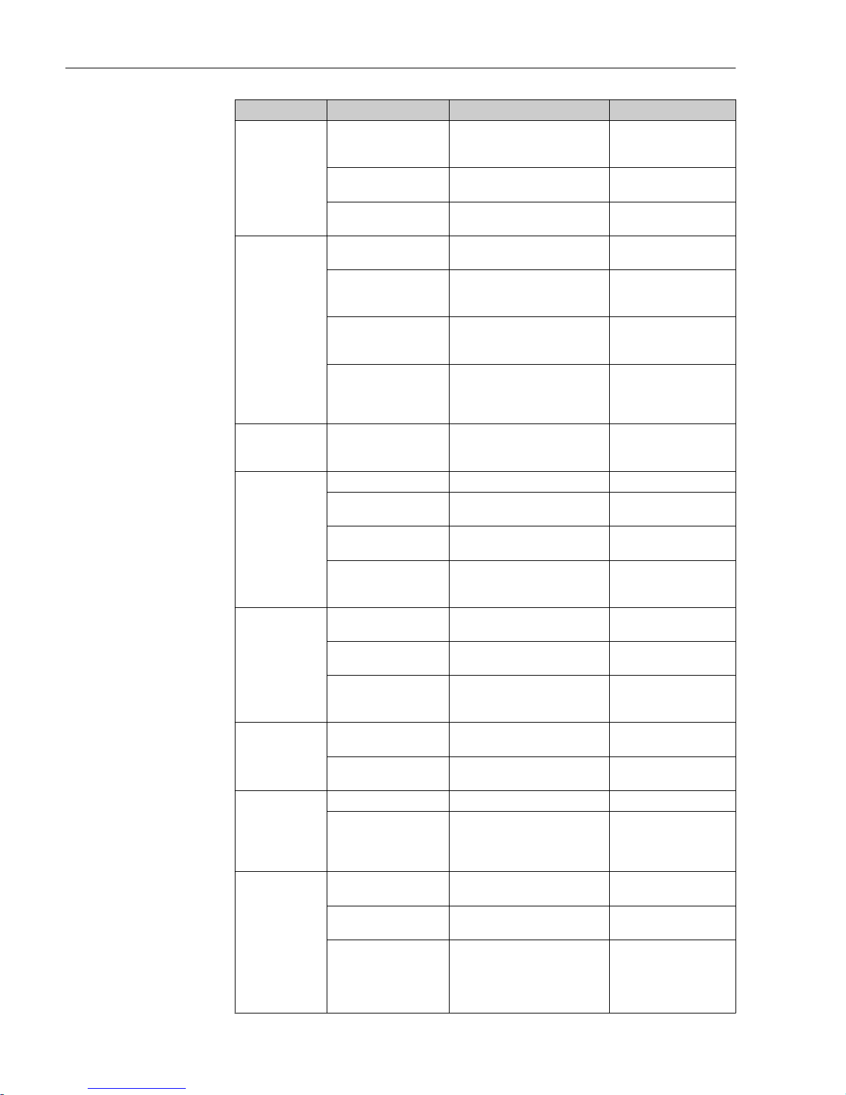
Diagnostics and troubleshooting Liquisys M CLM223/253
86 Endress+Hauser
Error Possible cause Tests/remedial action Tools, spare parts
Incorrect
temperature value
Incorrect sensor
connection
Check connections using wiring
diagram. Three-wire connection
always required.
Wiring diagram in
"Electrical connection"
section
Measuring cable
defective
Check cable for interruptions/
short-circuit/shunt.
Ohmmeter
Incorrect sensor type Set type of temperature sensor at
the device (field B1).
Fluctuations in
measured value
Interference on
measuring cable
Connect cable shield as per wiring
diagram
See the "Electrical
connection" section
Interference on signal
output cable
Check cable routing, possibly
route cable separately
Route signal output and
measuring input lines
separately
Interference potential in
medium
Eliminate source of interference
or ground medium as close as
possible to sensor.
Electromagnetic
interference on signal
lines with conductive
sensors
Use shielded cables and ground
the cable shield
Controller or timer
cannot be
activated
No relay module
available
Install LSR1-2 or LSR1-4 module
Controller/limit
contact does not
work
Controller switched off Activate controller See fields R2xx
Controller in operating
mode "Manual off"
Select "Auto" or "Manual on" mode Keyboard, REL key
Pickup delay setting too
long
Switch off or shorten pickup delay
time
See fields R2xx
"Hold" function active “Auto hold” for calibration,
“Hold” input activated;
“Hold” active via keyboard
See fields S2 to S5
Controller/limit
contact works
continuously
Controller in operating
mode "Manual on"
Select "Auto" or "Manual off" mode Keyboard, REL and AUTO
keys
Dropout delay setting too
long
Shorten dropout delay time See fields R2xx
Control loop interruption Check measured value, current
output value, actuators, chemical
supply
No conductivity
current output
signal
Cable disconnected or
short-circuited
Disconnect cable and measure
directly at device
mA meter 0–20 mA
Output defective See the "Device-specific errors"
section
Fixed conductivity
current output
signal
Current simulation active Switch off simulation. See field O3
Impermissible operating
state of processor system
Disconnect line voltage for
approx. 10 seconds
Possibly EMC problem: if
problem persists, check
grounding and wire
routing.
Incorrect current
output signal
Incorrect current
assignment
Check current assignment: 0–20
mA or 4–20 mA?
Field O311
Total load in the current
loop too high (> 500 Ω)
Disconnect output and measure
directly at device
mA meter for 0–20 mA
DC
EMC (interference
coupling)
Disconnect both output cables and
measure directly at device
Use shielded cables,
ground shields at both
ends, where necessary
route cable in another
cable duct
Page 87
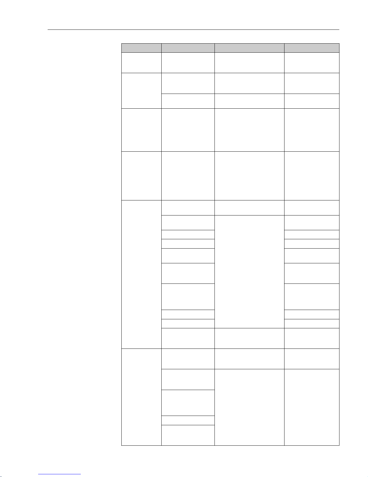
Liquisys M CLM223/253 Diagnostics and troubleshooting
Endress+Hauser 87
Error Possible cause Tests/remedial action Tools, spare parts
Current output
table is not
accepted
Value interval too small Select practical intervals
No temperature
output signal
Device does not have a
second current output
Check version using nameplate, if
necessary replace the LSCH-x1
module
LSCH-x2 module, see the
"Spare parts" section
Device with PROFIBUS-PAPA device has no current output!
Chemoclean
function not
available
No relay module (LSR1x) installed or only
LSR1-2 available
Additional function not
enabled
Install LSR1-4 module.
Chemoclean is enabled using the
release code supplied by the
manufacturer in the Chemoclean
retrofit kit.
To check the version, see the
nameplate
LSR1-4 module, see the
"Spare parts" section
Plus Package
functions not
available
Plus Package not enabled
(enable by entering a
code which depends on
the serial number and
which is supplied by E+H
when a Plus Package is
ordered)
• For Plus Package retrofit: code
is supplied by E+H → enter this
code.
• After replacing a defective
LSCH/LSCP module: first enter
device serial number manually
(see nameplate), then enter the
existing code number.
For a detailed description,
see the "Replacement of
central module" section.
No HART
communication
No HART central module Verify using nameplate: HART = -
xxx5xx and -xxx6xx
Upgrade to LSCH-H1 / H2
No or incorrect DD
(device description)
For further information, see
BA00208C/07/EN, "HART field
communication with Liquisys
CxM223/253”
HART interface missing
Current output < 4 mA
Load too small (must be
> 230 Ω)
HART receiver (e.g. FXA
191) not connected via
load but via power supply
Incorrect device address
(addr. = 0 for single
operation, addr. > 0 for
multidrop operation)
Line capacitance too high
Interference on line
Several devices set to
same address
Assign addresses correctly No communication
possible if several devices
set to the same address
No PROFIBUS
communication
No PA/DP central
module
Verify using the nameplate: PA =
-xxx3xx /DP = xxx4xx
Upgrade to LSCP module,
see the "Spare parts"
section
Incorrect device software
version (without
PROFIBUS)
For further information, see
BA00209C/07/EN "PROFIBUS
PA/DP - Field communication for
Liquisys CxM223/253".
Information about
PROFIBUS configuration is
provided in Technical
Information TI00260F,
while detailed information
about instrumentation
and accessories is provided
in Operating Instructions
BA00198F
With Commuwin (CW) II:
CW II version and device
software version
incompatible
No or incorrect DD/DLL
Incorrect baud rate
setting for segment
coupler in DPV-1 server
Page 88
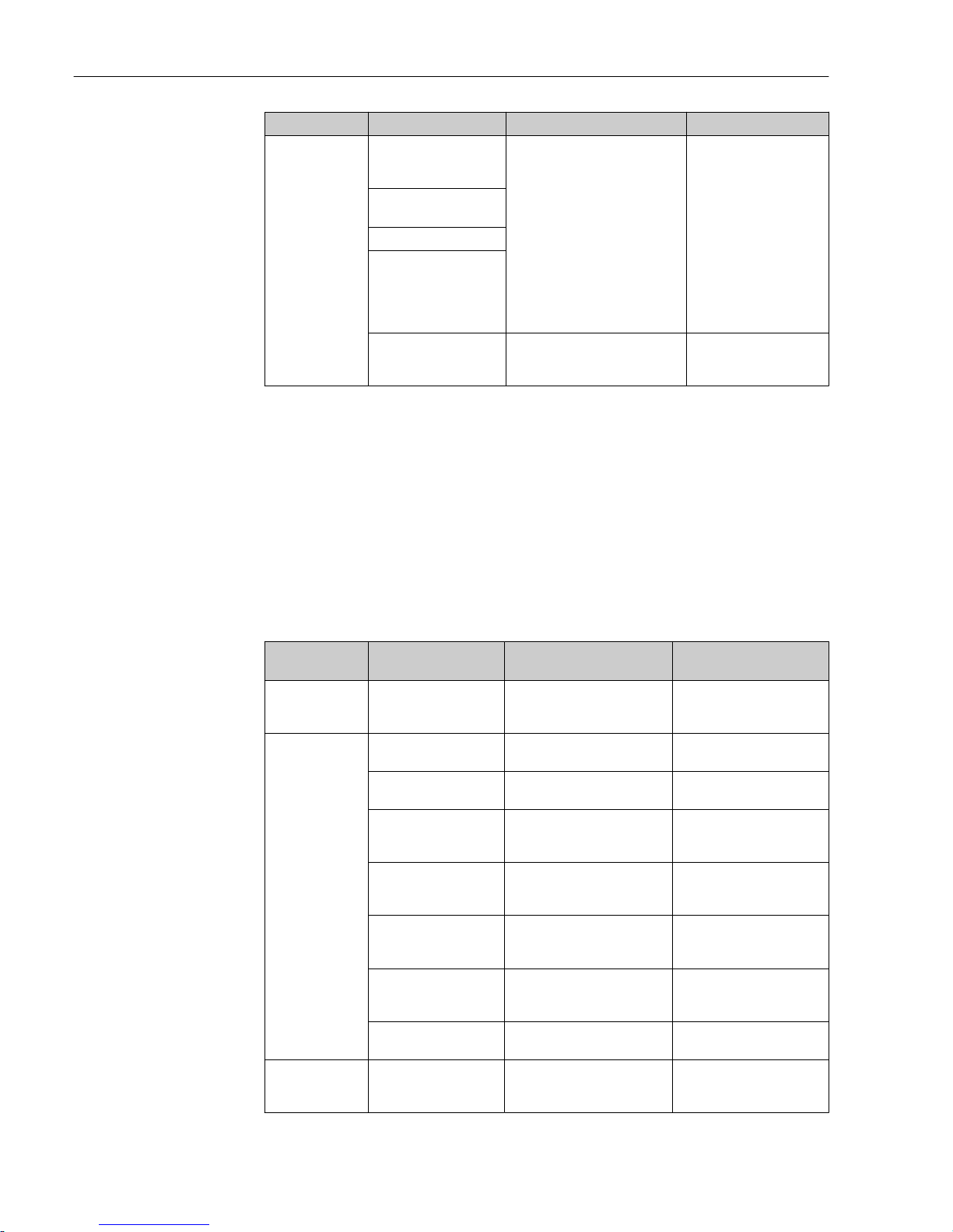
Diagnostics and troubleshooting Liquisys M CLM223/253
88 Endress+Hauser
Error Possible cause Tests/remedial action Tools, spare parts
Bus user (master) has
wrong address or address
assigned twice
Bus user (slave) has
wrong address
Bus line not terminated
Line problems (too long,
cross-section too small,
not shielded, shield not
grounded, wires not
twisted)
Bus voltage too low
(Bus voltage typ. 24 V DC
for non-Ex)
The voltage at the device's PA/DP
connector must be at least 9 V
8.4 Device-specific errors
The following table helps you during the diagnosis and points to any spare parts required.
Depending on the degree of difficulty and the measuring equipment present, diagnosis is
carried out by:
• Trained operator personnel
• The user's trained electrical technicians
• Company responsible for system installation/operation
• Endress+Hauser Service
Information on the exact spare part designations and on how to install these parts can be
found in the "Spare parts" section.
Error Possible cause Tests/remedial action Execution, tools, spare
parts
Device cannot be
operated, display
value 9999
Operation locked Press CAL and MINUS keys
simultaneously.
See the "Key functions"
section
Display dark, no
light-emitting
diode active
No line voltage Check whether line voltage is
present
Electrical technician / e.g.
multimeter
Supply voltage
wrong/too low
Compare actual line voltage
and nameplate data
User (data for energy supply
company or multimeter)
Connection faulty • Terminal not tightened
• Insulation jammed
• Wrong terminals used
Electrical technician
Device fuse defective Compare line voltage and the
nameplate data and replace
fuse
Electrical technician/suitable
fuse; see exploded drawing in
the the "Spare parts" section
Power unit defective Replace power unit, note
version
Onsite diagnosis by Endress
+Hauser Service, test module
necessary
Central module defective Replace central module, note
version
Onsite diagnosis by Endress
+Hauser Service, test module
necessary
Field device: ribbon cable
loose or defective
Check ribbon cable, replace if
necessary
See the "Spare parts" section
Display dark, lightemitting diode
active
Central module defective
(module: LSCH/LSCP)
Replace central module, note
version
Onsite diagnosis by Endress
+Hauser Service, test module
necessary
Page 89
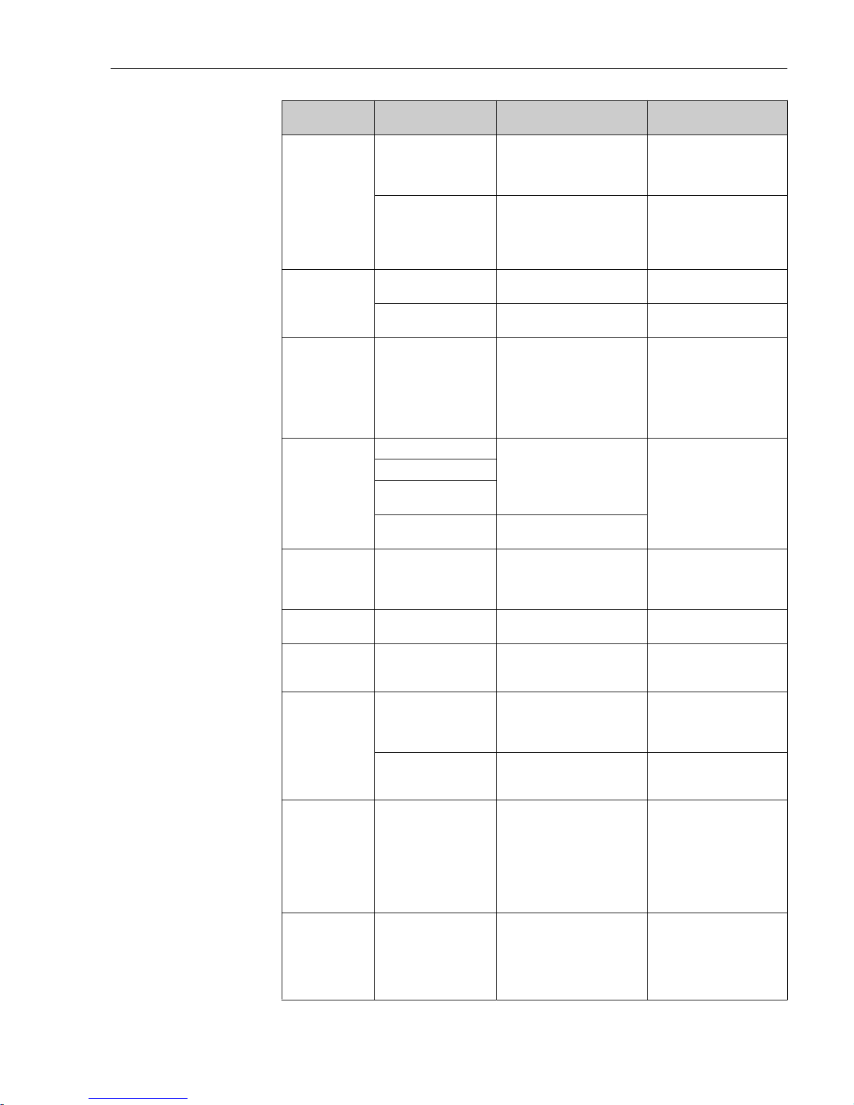
Liquisys M CLM223/253 Diagnostics and troubleshooting
Endress+Hauser 89
Error Possible cause Tests/remedial action Execution, tools, spare
parts
Values appear on
display but:
• Display does not
change and / or
• Device cannot
be operated
Device or module in
device not correctly
mounted
Panel-mounted device: reinstall
insert.
Field device: remount display
module
Perform with the aid of the
installation drawings in the
the "Spare parts" section
Impermissible operating
system condition
Disconnect line voltage for
approx. 10 seconds
Possibly Possible EMC
problem: if this persists,
check the installation or have
checked by Endress+Hauser
Service
Device gets hot Voltage wrong/too high Compare line voltage and
nameplate data
User, electrical technician
Power unit defective Replace power unit Diagnosis only by Endress
+Hauser Service
Conductivity/MΩ
measured value
and/or
temperature
measured value
incorrect
Transmitter module
defective (module:
MKIC), please first carry
out tests and take
measures as per the
"Process-specific errors"
section
Measuring input test:
• Connect a resistor instead of
the conductivity sensor
• 100 Ω resistance at
terminals 11/ 12 + 13 =
display 0 °C
If the test is negative: replace
module (note version).
Perform with the aid of the
exploded drawings in the
"Spare parts" section.
Current output,
incorrect current
value
Incorrect adjustment Check with integrated current
simulation, connect mA meter
directly to current output.
If simulation value incorrect:
adjustment in factory or new
LSCH module required.
If simulation value correct:
check current loop for load
and shunts.
Load too large
Shunt / short to ground
in current loop
Incorrect mode of
operation
Check whether 0–20 mA or 4–
20 mA is selected.
No current output
signal
Current output stage
defective (only for LSCH
module; LSCP has no
current output)
Check with integrated current
simulation, connect mA meter
directly to current output
If test negative:
Replace central module (note
version)
Additional relays
not working
Field device: ribbon cable
loose or defective
Check ribbon cable seating,
replace cable if required.
See the "Spare parts" section
Only 2 additional
relays can be
triggered
LSR1-2 relay module
with 2 relays is installed
Upgrade to LSR1-4 with 4
relays.
User or Endress+Hauser
Service
Additional
functions (Plus
Package) missing
No or incorrect release
code used
If retrofitting: check whether
the correct serial number was
quoted when ordering the Plus
Package.
Handled by Endress+Hauser
Sales
Incorrect device serial
number saved in LSCH/
LSCP module
Check whether serial number
on the nameplate matches SNR
in LSCH/ LSCP (field S 8).
The serial number of the
device is definitive for the
Plus Package.
Additional
functions (Plus
Package and/or
Chemoclean)
missing after
LSCH/LSCP
module
replacement
Replacement modules
LSCH or LSCP have the
device serial number
0000 when they leave
the factory. The Plus
Package or Chemoclean
are not enabled on
leaving the factory.
In the case of LSCH/LSCP with
SNR 0000, a device serial
number can be entered once in
fields E115 to E117.
Then enter the release codes
for the Plus Package and/or
Chemoclean if necessary.
For a detailed description,
see the "Replacement of
central module" section.
No HART or
PROFIBUS PA/DP
interface function
Incorrect central module HART: LSCH-H1 or H2 module,
PROFIBUS-PA: LSCP-PA
module,
PROFIBUS-DP: LSCP-DP
module,
see field E112.
Replace central module;
User or Endress+Hauser
Service.
Page 90
Maintenance Liquisys M CLM223/253
90 Endress+Hauser
Error Possible cause Tests/remedial action Execution, tools, spare
parts
Wrong software SW version, see field E111.
Bus problem Remove some devices and
repeat the test.
Contact Endress+Hauser
Service.
9 Maintenance
L
WARNING
Process pressure and temperature, contamination, electrical voltage
Risk of serious or fatal injury
‣
If the sensor has to be removed during maintenance work, avoid hazards posed by
pressure, temperature and contamination.
‣
Make sure the device is de-energized before you open it.
‣
Power can be supplied to switching contacts from separate circuits. De-energize these
circuits before working on the terminals.
Take all the necessary precautions in time to ensure the operational safety and reliability
of the entire measuring point.
The maintenance of the measuring point comprises:
• Calibration
• Cleaning the controller, assembly and sensor
• Checking the cables and connections
When performing any work on the device, bear in mind any potential impact this may
have on the process control system or on the process itself.
NOTICE
Electrostatic discharge (ESD)
Risk of damaging the electronic components
‣
Take personal protective measures to avoid ESD, such as discharging beforehand at PE
or permanent grounding with a wrist strap.
‣
For your own safety, only use genuine spare parts. With genuine parts, the function,
accuracy and reliability are also ensured after maintenance work.
9.1 Maintenance of the entire measuring point
9.1.1 Cleaning the transmitter
Clean the front of the housing using commercially available cleaning agents only.
The front of the housing is resistant to the following in accordance with DIN 42 115:
• Ethanol (for a short time)
• Diluted acids (max. 2% HCl)
• Diluted alkaline solutions (max. 3% NaOH)
• Soap-based household cleaning agents
When performing any work on the device, bear in mind any potential impact this may
have on the process control system or on the process itself.
Page 91
Liquisys M CLM223/253 Maintenance
Endress+Hauser 91
NOTICE
Prohibited cleaning agents
Damage to the housing surface or housing seal
‣
Never use concentrated mineral acids or alkaline solutions for cleaning.
‣
Never use organic cleaners such as benzyl alcohol, methanol, methylene chloride,
xylene or concentrated glycerol cleaner.
‣
Never use high-pressure steam for cleaning purposes.
9.1.2 Cleaning the conductivity sensors
L
CAUTION
Risk of injury from cleaning agents, damage to clothing and equipment
‣
Wear protective goggles and safety gloves.
‣
Clean away splashes on clothes and other objects.
‣
Pay particular attention to the information provided in the safety data sheets for the
chemicals used.
Clean away fouling on the sensor as follows depending on the type of fouling:
• Oily and greasy films:
Clean with grease remover, e.g. alcohol, acetone, possibly hot water and dishwashing
detergent.
• Lime and metal hydroxide buildup:
Dissolve buildup with diluted hydrochloric acid (3 %) and then rinse thoroughly with
plenty of clear water.
• Sulfidic buildup (from flue gas desulfurization or sewage treatment plants):
Use a mixture of hydrochloric acid (3 %) and thiocarbamide (commercially available) and
then rinse thoroughly with plenty of clear water.
• Buildup containing proteins (e.g. food industry):
Use a mixture of hydrochloric acid (0.5 %) and pepsin (commercially available) and then
rinse thoroughly with plenty of clear water.
9.1.3 Simulation of conductive sensors for device testing
You can test the transmitter for conductive conductivity by replacing the measurement
section and temperature sensor with resistors. The accuracy of the simulation will depend
on the accuracy of the resistors.
Temperature
If a temperature offset is not set at the transmitter, the temperature values of the
following table apply:
Pt 100 equivalent resistors
Temperature Resistance value
-20 °C (-4 °F) 92.13 Ω
-10 °C (14 °F) 96.07 Ω
0 °C (32 °F) 100.00 Ω
10 °C (50 °F) 103.90 Ω
20 °C (68 °F) 107.79 Ω
25 °C (77 °F) 109.73 Ω
50 °C (122 °F) 119.40 Ω
80 °C (176 °F) 130.89 Ω
100 °C (212 °F) 138.50 Ω
200 °C (392 °F) 175.84 Ω
Page 92
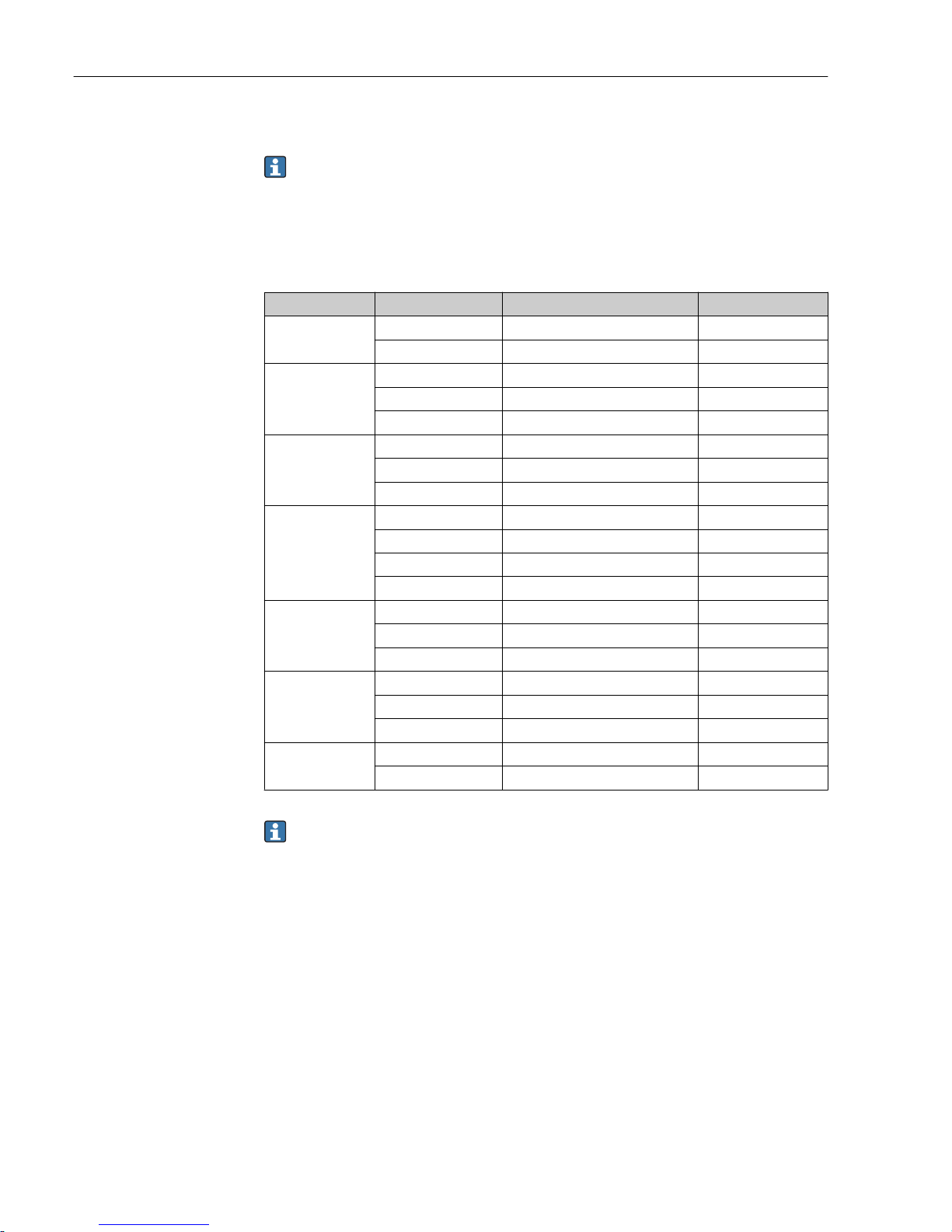
Maintenance Liquisys M CLM223/253
92 Endress+Hauser
With the Pt 1000 type of temperature sensor, all the resistance values are increased by a
factor of 10.
Attach the temperature equivalent resistor in a three-wire system.
Conductivity
If the cell constant k is set to the value in column 2 of the following table, then the
conductivity values of this table apply.
Otherwise the following applies: Conductivity [mS/cm] = k[cm-1] ⋅ 1 / R[kΩ]
Resistance R Cell constant k Display for conductivity Display for MΩ
10 Ω 1 cm
-1
100 mS/cm
10 cm
-1
1000 mS/cm
100 Ω 0.1 cm
-1
1 mS/cm 1 kΩ ⋅ cm
1 cm
-1
10 mS/cm
10 cm
-1
100 mS/cm
1000 Ω 0.1 cm
-1
0.1 mS/cm 10 kΩ ⋅ cm
1 cm
-1
1 mS/cm
10 cm
-1
10 mS/cm
10 kΩ 0.01 cm
-1
1 μS/cm 1 MΩ ⋅ cm
0.1 cm
-1
10 μS/cm 100 kΩ ⋅ cm
1 cm
-1
100 μS/cm
10 cm
-1
1 mS/cm
100 kΩ 0.01 cm
-1
0.1 μS/cm 10 MΩ ⋅ cm
0.1 cm
-1
1 μS/cm 1 MΩ ⋅ cm
1 cm
-1
10 μS/cm
1 MΩ 0.01 cm
-1
0.01 μS/cm 100 MΩ ⋅ cm
0.1 cm
-1
0.1 μS/cm 10 MΩ ⋅ cm
1 cm
-1
1 μS/cm
10 MΩ 0.01 cm
-1
0.001 μS/cm
0.1 cm
-1
0.01 μS/cm 100 MΩ ⋅ cm
The MΩ measurement is normally used for pure and ultrapure water and therefore
only makes sense for cell constants k= 0.01 cm-1 or k = 0.1 cm-1.
9.1.4 Simulation of inductive sensors for device testing
The inductive sensor cannot be simulated.
However, the overall system comprising the transmitter and inductive sensor can be tested
using equivalent resistors. Note the cell constant k (e.g. k
nominal
= 1.98 cm-1 for CLS50,
k
nominal
= 5.9 cm-1 for CLS52, k
nominal
= 6.3 cm-1 for CLS54).
For accurate simulation, the actual cell constant used (visible in field C124) must be used
to calculate the display value.
The formula for calculation also depends on the type of sensor:
• CLS50 and CLS52: conductivity reading [mS/cm] = k[cm-1] ⋅1/R[kΩ]
• CLS54: conductivity reading [mS/cm] = k[cm-1] ⋅1/R[kΩ] ⋅ 1.21
Page 93
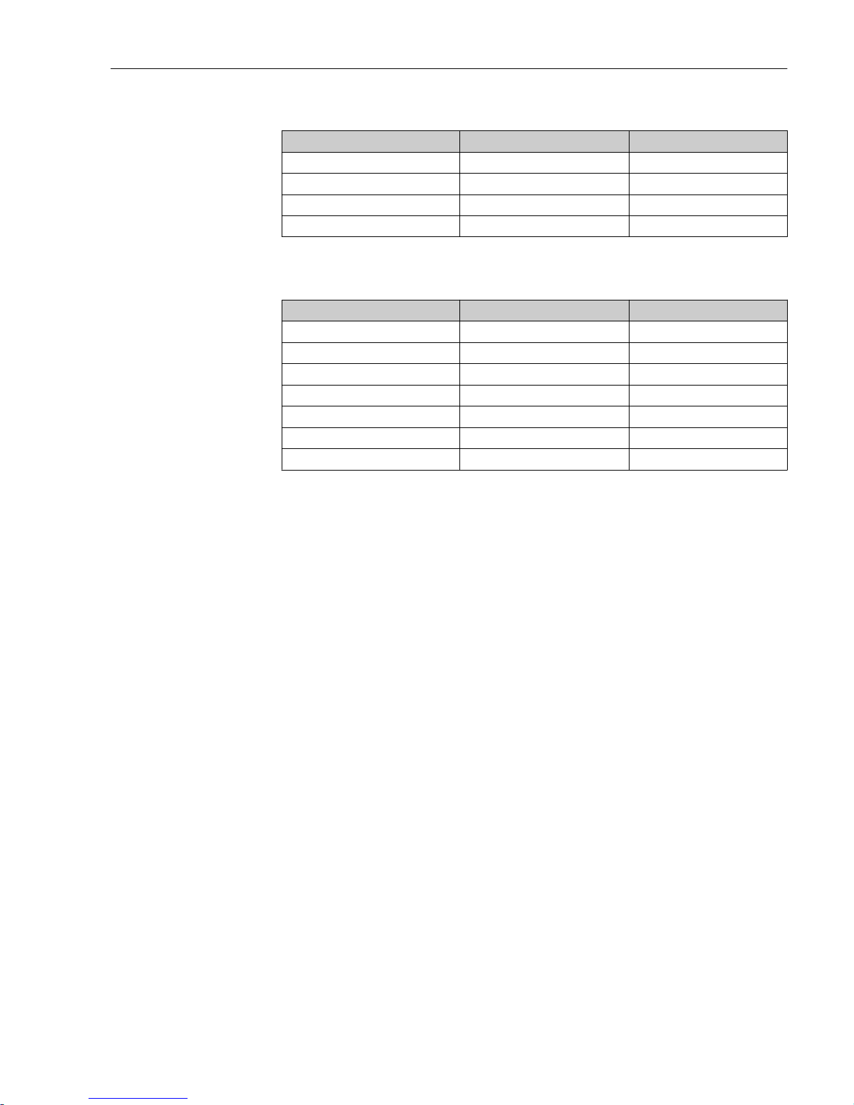
Liquisys M CLM223/253 Maintenance
Endress+Hauser 93
Values for simulation with CLS50 at 25 °C (77 °F):
Simulation resistance R Default cell constant k Conductivity reading
2 Ω 1.98 cm
-1
990 mS/cm
10 Ω 1.98 cm
-1
198 mS/cm
100 Ω 1.98 cm
-1
19.8 mS/cm
1 kΩ 1.98 cm
-1
1.98 mS/cm
Simulation with CLS54 at 25 °C (77 °F):
Simulation resistance R Default cell constant k Conductivity reading
10 Ω 6.3 cm
-1
520 mS/cm
26 Ω 6.3 cm
-1
200 mS/cm
100 Ω 6.3 cm
-1
52 mS/cm
260 Ω 6.3 cm
-1
20 mS/cm
2.6 kΩ 6.3 cm
-1
2 mS/cm
26 kΩ 6.3 cm
-1
200 μS/cm
52 kΩ 6.3 cm
-1
100 μS/cm
Conductivity simulation:
Pull a cable through the sensor opening and then connect it to a decade resistor, for
instance.
9.1.5 Checking conductive sensors
• Measuring surface connection:
The measuring surfaces are directly connected to the connections of the sensor
connector. Check with ohmmeter for < 1 Ω.
• Measuring surface shunt:
A shunt is not permitted between the measuring surfaces. Check with ohmmeter for >
20 MΩ.
• Temperature sensor shunt:
A shunt is not permitted between the measuring surfaces and the temperature sensor.
Check with ohmmeter for > 20 MΩ.
• Temperature sensor:
See the sensor nameplate for information on the type of the temperature sensor being
used.
The sensor can be checked at the sensor connector with an ohmmeter:
– Pt 100 at 25 °C (77 °F) = 109.79 Ω
– Pt 1000 at 25 °C (77 °F) = 1097.9 Ω
– NTC 30 k at 25 °C (77 °F) = 30 kΩ
• Terminal:
For sensors with a terminal connection (CLS12/13) check the assignment of the
terminals to ensure they have not been inadvertently interchanged. Check the tightness
of the terminal screws.
Page 94

Maintenance Liquisys M CLM223/253
94 Endress+Hauser
9.1.6 Checking inductive sensors
The following applies to the CLS50, CLS52 and CLS54 sensors.
The sensor cables must be disconnected at the device or junction box for all tests described
here!
• Testing the transmitting and receiving coils:
Perform the measurement at the white and red coaxial cables, between the inner
conductor and shield in each case.
– Ohmic resistance
CLS50/52: approx. 0.5 to 2 Ω
CLS54: approx. 1 to 3 Ω
– Inductance approx. 180 to 500 mH (for 2 kHz, series circuit as equivalent circuit
diagram)
CLS50: approx. 250 to 450 mH
CLS52/54: approx. 180 to 550 mH
• Testing the coil shunt:
A shunt is not permitted between the two sensor coils (from red coax to white coax). The
measured resistance must be > 20 MΩ.
Test with the ohmmeter from the red coax cable to the white coax cable.
• Temperature sensor test:
Use the table in the "Simulation of conductive sensors for device testing" section to check
the Pt 100 / Pt 1000 in the sensor.
Measure between the green and white wires and between the green and yellow wires.
The resistance values must be identical.
• Temperature sensor shunt test:
Shunts are not permitted between the temperature sensor and the coils. Check with
ohmmeter for > 20 MΩ
Measure between the temperature sensor wires (green + white + yellow) and the coils
(red and white coax).
9.1.7 Assembly
Refer to the assembly operating manual for information on servicing and troubleshooting
the assembly. The assembly operating manual describes the procedure for mounting and
disassembling the assembly, replacing the sensors and seals, and contains information on
the material resistance properties, as well as on spare parts and accessories.
9.1.8 Connecting cables and junction boxes
• Use the methods described in chapters "Simulation of conductive/inductive sensors for
device test" to perform a quick functional check from the conductivity sensor (sensor
connector) to the measuring instrument via an extension. The easiest way to connect
resistor decades is with the "Conductivity testing adapter" service kit, order number:
51500629
• Check junction boxes for:
– Moisture (influence at low conductivity or for MΩ measurement, where necessary dry
box, replace seals, insert dehydrating bag)
– Correct connection of all lines
– Connection of the outer shields
– Tightness of the terminal screws
Page 95
Liquisys M CLM223/253 Repair
Endress+Hauser 95
10 Repair
10.1 Spare parts
Please order spare parts from your local Sales Office. For this purpose, use the order
numbers listed in the "Spare part kits" section.
For safety, you should always provide the following additional data when ordering spare
parts:
• Device order code
• Serial number
• Software version, if possible
You can take the order code and serial number from the nameplate.
The software version is provided in the device software provided that the device processor
system is still working.
For more detailed information on spare parts kits, please refer to the "Spare Part Finding
Tool" on the Internet:
www.endress.com/spareparts_consumables
10.2 Disassembling the panel-mounted device
Please note the effects on the process if the device is taken out of service!
See the exploded drawing for the item numbers.
1. Disconnect the terminal block (item 420 b) from the rear of the device to de-energize
the device.
2. Then disconnect the terminal blocks (item 420 a and 430 where applicable) from the
rear of the device. Now you can disassemble the device.
3. Press in the latches of the end frame (item 340) and remove the frame from the rear.
4. Release the special screw (item 400) by turning it counter-clockwise.
5. Remove the entire electronics block from the housing. The modules are only
mechanically connected and can be easily separated:
6. Simply remove the processor/display module towards the front.
7. Pull out the brackets of the rear plate (item 320) slightly.
8. Now you can remove the side modules.
9. Remove the conductivity transmitter (item 240) as follows:
10. Using a fine wire cutter, nip off the heads of the synthetic distance holders.
11. Then remove the module from above.
Assembly is the reverse of the disassembly sequence. Tighten the special screw fingertight without using a tool.
Page 96
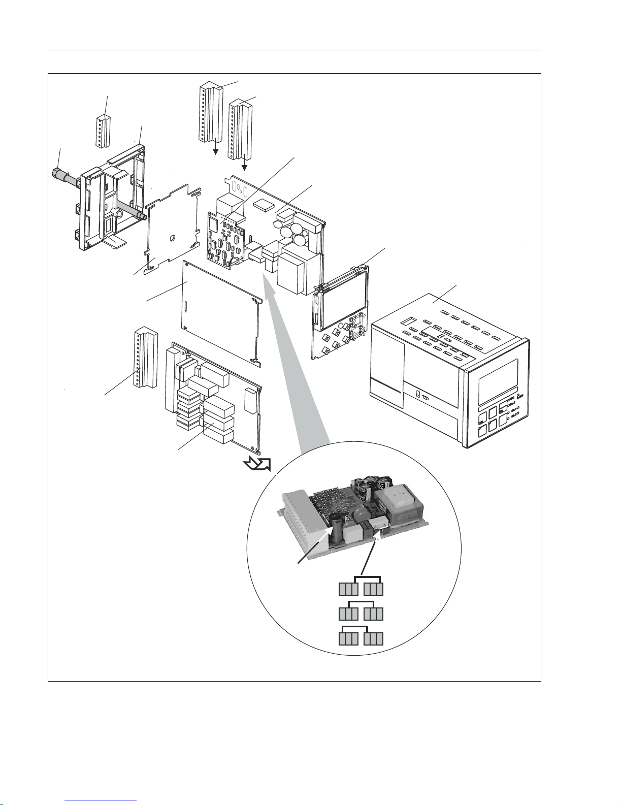
Repair Liquisys M CLM223/253
96 Endress+Hauser
230V
100V
115V
400
345
340
420a
420b
320
240
15/20
40 ... 91
330
15
A
B
290/300
430
310
A0008913
39 Exploded drawing of panel-mounted device
Page 97
Liquisys M CLM223/253 Repair
Endress+Hauser 97
The exploded drawing contains the components and spare parts of the panel-mounted
device. You can take the spare parts and the corresponding order number from the
following section using the item numbers.
Item Kit description Name Function/contents Order no.
15 Power unit (main module) LSGA 100/115/230 V AC 51500317
20 Power unit (main module) LSGD 24 V AC + DC 51500318
40 Central module (contr.),
conductive
LSCH-S1 1 current output 51501210
50 Central module (contr.),
conductive
LSCH-S2 2 current outputs 51501212
60 Central module (contr.),
conductive
LSCH-H1 1 current output + HART 51501213
70 Central module (contr.),
conductive
LSCH-H2 2 current outputs + HART 51501214
80 Central module (contr.),
conductive
LSCP-PA PROFIBUS PA/no current output 51501215
90 Central module (contr.),
conductive
LSCP-DP PROFIBUS DP/no current output 51502502
90 Kit for CLM2x3
conductivity central
module, conductive,
PROFIBUS DP
LSCP-DP PROFIBUS DP central module
Relay module + 2 relays
Current inp. + DP terminals
Hardware version 2.10 and higher
71134726
41 Central module (contr.),
inductive
LSCH-S1 1 current output 51501216
51 Central module (contr.),
inductive
LSCH-S2 2 current outputs 51501218
61 Central module (contr.),
inductive
LSCH-H1 1 current output + HART 51501219
71 Central module (contr.),
inductive
LSCH-H2 2 current outputs + HART 51501220
81 Central module (contr.),
inductive
LSCP-PA PROFIBUS PA/no current output 51501221
91 Central module (contr.),
inductive
LSCP-DP PROFIBUS DP/no current output 51502501
91 Kit for CLM2x3
conductivity central
module, inductive,
PROFIBUS DP
LSCP-DP PROFIBUS DP central module
Relay module + 2 relays
Current inp. + DP terminals
Hardware version 2.10 and higher
71134727
240 Conductivity transmitter
(hazardous area version)
MKIC Conductivity + temperature input 71161137
Conductivity transmitter MKIC Conductivity + temperature input 71161133
290 Relay module LSR1-2 2 relays 51500320
290 Relay module LSR2-2i 2 relays + 4-20 mA current input 51504304
290 Kit for Cxm2x3 relay
module
PROFIBUS DP
LSR2-DP Relay module + 2 relays
Curr. input + DP terminals
Hardware version 2.10 and higher
71134732
300 Relay module LSR1-4 4 relays 51500321
300 Relay module LSR2-4i 4 relays + 4-20 mA current input 51504305
310 Side panel Kit with 10 parts 51502124
310, 320,
340, 400
Housing mechanical parts Rear plate, side panel, end frame,
special screw
51501076
Page 98
Repair Liquisys M CLM223/253
98 Endress+Hauser
Item Kit description Name Function/contents Order no.
330, 400 Housing module Housing with front membrane, sensory
tappets, seal, special screw, tensioning
dogs, connection plates and nameplates
51501075
340 End frame
PROFIBUS-DP
Rear frame for PROFIBUS DP, with Dsubmin plug connector
51502513
345 Grounding terminal strip PE and shielding terminals 51501086
420a,
420b
Terminal strip set Complete terminal strip set, standard +
HART
51501203
420a,
420b
Terminal strip set Complete terminal strip set
PROFIBUS PA
51502126
420a,
420b
Terminal strip set Complete terminal strip set
PROFIBUS DP
51502493
430 Terminal strip Terminal strip for relay module 51501078
A Fuse Part of power unit, item 15
B Choice of line voltage Position of jumper on power unit, item
15 depending on line voltage
10.3 Disassembling the field device
Please note the effects on the process if the device is taken out of service!
See the exploded drawing for the item numbers.
You require the following tools to disassemble the field device:
• Standard set of screwdrivers
• Torx screwdriver, size TX 20
Proceed as follows to disassemble the field device:
1. Open and remove the cover of the connection compartment (item 420).
2. Disconnect the supply terminal (item 470) to de-energize the device.
3. Open the display cover (item 410) and release the ribbon cables (item 310/320) on
the central module side (item 40 to 91) .
4. To remove the central module (item 40) release the screw in the display cover (item
450 b).
5. Proceed as follows to remove the electronics box (item 330):
6. Turn the screws in the housing base (item 450 a) by two revolutions to release them.
7. Then push the entire box backwards and remove it from above while making sure
that the module locks do not open.
8. Release the ribbon cables (item 310/320).
9. Bend the module locks out and remove the modules.
10. To remove the docking module (item 340) remove the screws in the housing base
(item 450 c) and remove the entire assembly from above.
11. To remove the conductivity transmitter (item 240) nip off the heads of the synthetic
distance sleeves using a fine wire cutter.
12. Then remove the module from above.
Page 99

Liquisys M CLM223/253 Repair
Endress+Hauser 99
To assemble, carefully push the modules into the guide rails of the electronics box and let
them engage in the side box noses.
It is not possible to mount the modules incorrectly. Modules inserted in the electronics
box incorrectly are not operable since the ribbon cables cannot be connected.
Make sure the cover seals are intact to guarantee IP 65 ingress protection.
Page 100
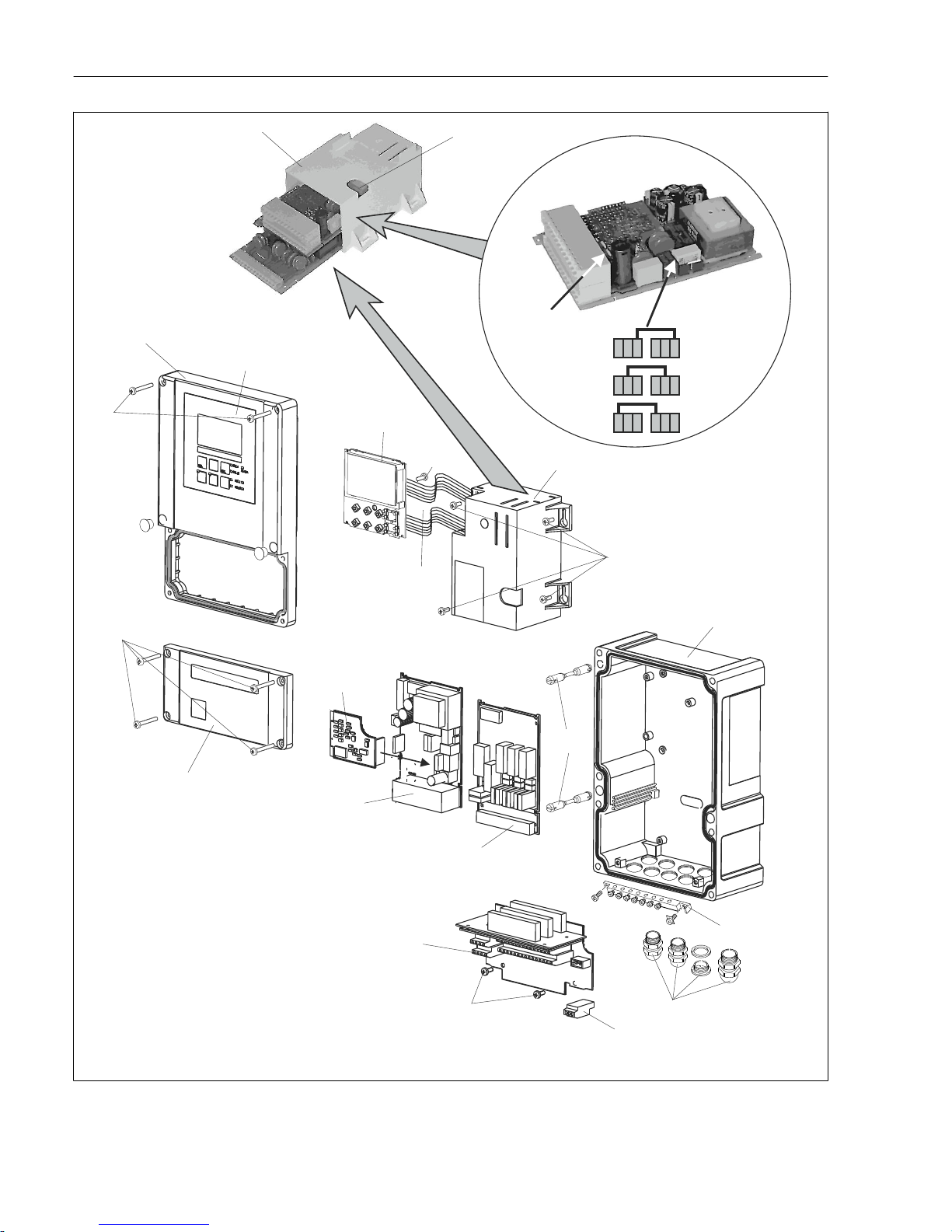
Repair Liquisys M CLM223/253
100 Endress+Hauser
100 V
Pos. 10
Netzteil 100 – 230 V AC
230 V
115 V
Sicherung
15
C
D
460a
420
40 ... 91
310/320
240
15/20
340
450c
470
480
290/300
400
430
450a
330
410
460b
370
A
B
450b
403
A0008916
40 Field device exploded drawing
 Loading...