

Page 1
Products Solutions Services
BA00237C/07/EN/14.13
71230970
valid as of:
software version 1.12
Operating Instructions
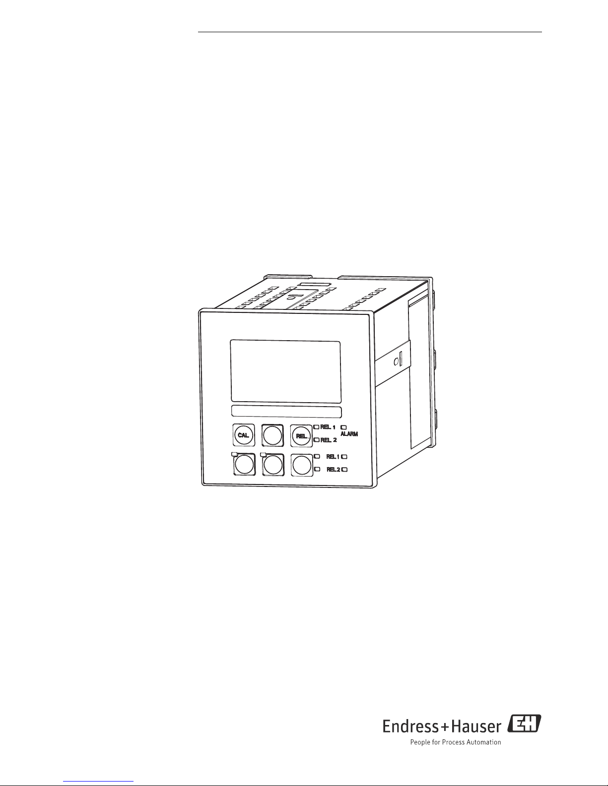
Liquisys M CLM223F
Transmitter for Conductivity
Page 2
Endress+Hauser
About this document
Safety messages
The structure, signal words and safety colors of the signs comply with the specifications of
ANSI Z535.6 ("Product safety information in product manuals, instructions and other
collateral materials").
Symbols
Safety message structure Meaning
DANGER
!
Cause (/consequences)
Consequences if safety
message is not heeded
‣ Corrective action
This symbol alerts you to a dangerous situation.
Failure to avoid the situation will result in a fatal or serious
injury.
WARNING
!
Cause (/consequences)
Consequences if safety
message is not heeded
‣ Corrective action
This symbol alerts you to a dangerous situation.
Failure to avoid the situation can result in a fatal or serious
injury.
CAUTION
!
Cause (/consequences)
Consequences if safety
message is not heeded
‣ Corrective action
This symbol alerts you to a dangerous situation.
Failure to avoid this situation can result in minor or
medium injury.
NOTICE
Cause/situation
Consequences if safety
message is not heeded
‣ Action/note
This symbol alerts you to situations that can result in
damage to property and equipment.
Additional information, tips
Permitted or recommended
Forbidden or not recommended
Page 3

Liquisys M CLM223F
Endress+Hauser 3
Table of contents
1 Basic safety instructions . . . . . . . . . . . . . 5
1.1 Requirements for the personnel . . . . . . . . . . . . . . . 5
1.2 Designated use . . . . . . . . . . . . . . . . . . . . . . . . . . . . . 5
1.3 Workplace safety . . . . . . . . . . . . . . . . . . . . . . . . . . . 5
1.4 Operational safety . . . . . . . . . . . . . . . . . . . . . . . . . . . 5
1.5 Product safety . . . . . . . . . . . . . . . . . . . . . . . . . . . . . . 6
1.6 Electrical symbols . . . . . . . . . . . . . . . . . . . . . . . . . . . 6
2 Incoming acceptance and product
identification . . . . . . . . . . . . . . . . . . . . . . 7
2.1 Incoming acceptance . . . . . . . . . . . . . . . . . . . . . . . . 7
2.2 Scope of delivery . . . . . . . . . . . . . . . . . . . . . . . . . . . . 7
2.3 Product identification . . . . . . . . . . . . . . . . . . . . . . . . 7
2.3.1 Nameplate . . . . . . . . . . . . . . . . . . . . . . . . . . . 7
2.3.2 Identifying the product . . . . . . . . . . . . . . . . 7
2.4 Certificates and approvals . . . . . . . . . . . . . . . . . . . . 8
2.4.1 CE mark . . . . . . . . . . . . . . . . . . . . . . . . . . . . . 8
2.4.2 CSA general purpose . . . . . . . . . . . . . . . . . . 8
3 Mounting. . . . . . . . . . . . . . . . . . . . . . . . . . 9
3.1 Quick installation guide . . . . . . . . . . . . . . . . . . . . . . 9
3.1.1 Measuring system . . . . . . . . . . . . . . . . . . . . 9
3.2 Installation conditions . . . . . . . . . . . . . . . . . . . . . 10
3.3 Installation instructions . . . . . . . . . . . . . . . . . . . . 11
3.4 Post-installation check . . . . . . . . . . . . . . . . . . . . . 11
4 Electrical connection . . . . . . . . . . . . . . . 12
4.1 Wiring . . . . . . . . . . . . . . . . . . . . . . . . . . . . . . . . . . 12
4.1.1 Connection diagram . . . . . . . . . . . . . . . . . 13
4.1.2 Measuring cable and sensor connection 15
4.1.3 Alarm contact . . . . . . . . . . . . . . . . . . . . . . 16
4.2 Post-connection check . . . . . . . . . . . . . . . . . . . . . 17
5 Operability. . . . . . . . . . . . . . . . . . . . . . . . 18
5.1 Display and operating elements . . . . . . . . . . . . . 18
5.1.1 Display . . . . . . . . . . . . . . . . . . . . . . . . . . . . 18
5.1.2 Operating elements . . . . . . . . . . . . . . . . . 19
5.1.3 Key assignment . . . . . . . . . . . . . . . . . . . . 20
5.2 Local Operation . . . . . . . . . . . . . . . . . . . . . . . . . . . 22
5.2.1 Automatic/manual mode . . . . . . . . . . . . 22
5.2.2 Operating concept . . . . . . . . . . . . . . . . . . 23
6 Commissioning . . . . . . . . . . . . . . . . . . . 25
6.1 Function check . . . . . . . . . . . . . . . . . . . . . . . . . . . . 25
6.2 Switching on . . . . . . . . . . . . . . . . . . . . . . . . . . . . . . 25
6.3 Quick start-up . . . . . . . . . . . . . . . . . . . . . . . . . . . . . 27
6.4 System configuration . . . . . . . . . . . . . . . . . . . . . . . 30
6.4.1 Setup 1 (Conductivity) . . . . . . . . . . . . . . . . 30
6.4.2 Setup 2 (Temperature) . . . . . . . . . . . . . . . 32
6.4.3 Current outputs . . . . . . . . . . . . . . . . . . . . . 35
6.4.4 Alarm . . . . . . . . . . . . . . . . . . . . . . . . . . . . . 36
6.4.5 Check . . . . . . . . . . . . . . . . . . . . . . . . . . . . . . 37
6.4.6 Relay contact configuration . . . . . . . . . . . 38
6.4.7 Temperature compensation with table . . 40
6.4.8 Determination of the temperature
coefficient . . . . . . . . . . . . . . . . . . . . . . . . . . 41
6.4.9 Concentration measurement . . . . . . . . . . 42
6.4.10 Service . . . . . . . . . . . . . . . . . . . . . . . . . . . . . 46
6.4.11 E+H Service . . . . . . . . . . . . . . . . . . . . . . . . . 49
6.4.12 Remote measuring range switching
(MRS) . . . . . . . . . . . . . . . . . . . . . . . . . . . . . 50
6.5 Calibration . . . . . . . . . . . . . . . . . . . . . . . . . . . . . . . . 53
7 Diagnostics and troubleshooting . . . . 56
7.1 Troubleshooting instructions . . . . . . . . . . . . . . . . 56
7.2 System error messages . . . . . . . . . . . . . . . . . . . . . 56
7.3 Process specific errors . . . . . . . . . . . . . . . . . . . . . . 58
7.4 Instrument specific errors . . . . . . . . . . . . . . . . . . . 61
8 Maintenance . . . . . . . . . . . . . . . . . . . . . 62
8.1 Maintenance of the entire measuring point . . . . 62
8.1.1 Cleaning the transmitter . . . . . . . . . . . . . . 62
8.1.2 Cleaning the conductivity sensors . . . . . . 63
8.1.3 Simulation of conductive sensors for
device test . . . . . . . . . . . . . . . . . . . . . . . . . . 63
8.1.4 Simulation of inductive sensors for
device test . . . . . . . . . . . . . . . . . . . . . . . . . . 65
8.1.5 Check of conductive sensors . . . . . . . . . . . 65
8.1.6 Check of inductive sensors . . . . . . . . . . . . 66
8.1.7 Connecting lines and junction boxes . . . . 66
9 Repair . . . . . . . . . . . . . . . . . . . . . . . . . . . 67
9.1 Spare parts . . . . . . . . . . . . . . . . . . . . . . . . . . . . . . . . 67
9.2 Dismantling the panel-mounted instrument . . . 67
9.3 Replacing the central module . . . . . . . . . . . . . . . . 70
9.4 Return . . . . . . . . . . . . . . . . . . . . . . . . . . . . . . . . . . . 70
9.5 Disposal . . . . . . . . . . . . . . . . . . . . . . . . . . . . . . . . . . 70
10 Accessories. . . . . . . . . . . . . . . . . . . . . . . 71
10.1 Sensors . . . . . . . . . . . . . . . . . . . . . . . . . . . . . . . . . . . 71
10.2 Connection accessories . . . . . . . . . . . . . . . . . . . . . 71
10.3 Hardware add-ons . . . . . . . . . . . . . . . . . . . . . . . . . 71
10.4 Calibration solutions . . . . . . . . . . . . . . . . . . . . . . . 72
Page 4

Liquisys M CLM223F
4 Endress+Hauser
11 Technical data. . . . . . . . . . . . . . . . . . . . .73
11.1 Input . . . . . . . . . . . . . . . . . . . . . . . . . . . . . . . . . . . . . 73
11.2 Output . . . . . . . . . . . . . . . . . . . . . . . . . . . . . . . . . . . 74
11.3 Power supply . . . . . . . . . . . . . . . . . . . . . . . . . . . . . . 75
11.4 Performance characteristics . . . . . . . . . . . . . . . . . 75
11.5 Environment . . . . . . . . . . . . . . . . . . . . . . . . . . . . . . 76
11.6 Mechanical construction . . . . . . . . . . . . . . . . . . . . 76
12 Appendix . . . . . . . . . . . . . . . . . . . . . . . . .78
Index. . . . . . . . . . . . . . . . . . . . . . . . . . . . .81
Page 5

Liquisys M CLM223F Basic safety instructions
Endress+Hauser 5
1 Basic safety instructions
1.1 Requirements for the personnel
‣
Installation, commissioning, operation and maintenance of the measuring system must
only be carried out by trained technical personnel.
‣ The technical personnel must be authorized by the plant operator to carry out the
specified activities.
‣ The electrical connection may only be performed by an electrical technician.
‣ The technical personnel must have read and understood these Operating Instructions
and must follow the instructions they contain.
‣ Measuring point faults may only be rectified by authorized and specially trained
personnel.
Repairs not described in the enclosed Operating Instructions may only be carried out
directly at the manufacturer's or by the service organization.
1.2 Designated use
CLM223 F is a transmitter for determining the conductivity of a liquid medium.
The transmitter is particularly suited for use in the following areas:
• Concentration control
•CIP plants control
• Phase separation
• Product quality assurance
• Wash mobiles and cleaning plants
Any other use than the one described here compromises the safety of persons and the entire
measuring system and is, therefore, not permitted.
The manufacturer is not liable for damage caused by improper or non-designated use.
1.3 Workplace safety
As the user, you are responsible for complying with the following safety conditions:
• Regulations for explosion protection
• Installation instructions
• Local standards and regulations
Electromagnetic compatibility
With regard to electromagnetic compatibility, this device has been tested in accordance with
the applicable European standards for industrial applications.
The electromagnetic compatibility indicated only applies to a device that has been connected
in accordance with the instructions in these Operating Instructions.
1.4 Operational safety
‣
Before commissioning the entire measuring point, make sure all the connections are
correct. Ensure that electrical cables and hose connections are not damaged.
‣ Do not operate damaged products, and safeguard them to ensure that they are not
operated inadvertently. Mark the damaged product as defective.
‣ If faults cannot be rectified, the products must be taken out of service and secured against
unintentional commissioning.
Page 6
Basic safety instructions Liquisys M CLM223F
6 Endress+Hauser
1.5 Product safety
The product is designed to meet state-of-the-art safety requirements, has been tested and
left the factory in a condition in which it is safe to operate. Relevant regulations and
European standards have been observed.
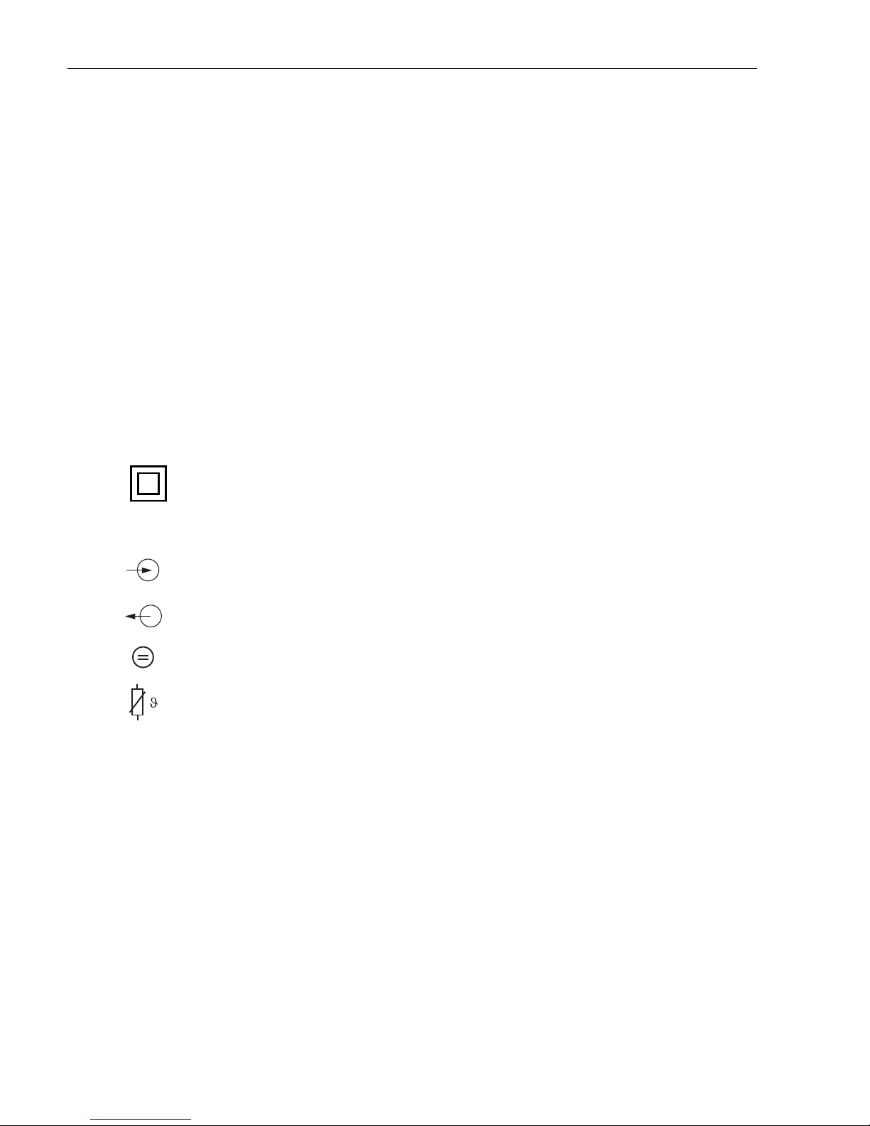
1.6 Electrical symbols
%
Direct Current (DC)
A terminal at which DC is applied or through which DC flows.
&
Alternating Current (AC)
A terminal at which (sine-form) AC is applied or through which AC flows.
)
Ground connecting
A terminal which, from the user’s point of view, is already grounded using a grounding
system.
*
Protective ground terminal
A terminal which must be grounded before other connections may be set up.
Class II (isolated ) device
Double insulation
b
Alarm relay
Input
Output
DC voltage source
Temperature sensor
Page 7

Liquisys M CLM223F Incoming acceptance and product identification
Endress+Hauser 7
2 Incoming acceptance and product
identification
2.1 Incoming acceptance
‣
Make sure the packaging is undamaged!
‣ Inform the supplier about any damage to the packaging.
Keep the damaged packaging until the matter has been settled.
‣ Make sure the contents are undamaged!
‣ Inform the supplier about damage to the contents. Keep the damaged products until the
matter has been settled.
‣ Check that the order is complete and agrees with your shipping documents.
‣ The packaging material used to store or to transport the product must provide shock
protection and humidity protection. The original packaging offers the best protection.
Also, keep to the approved ambient conditions (see "Technical data").
‣ If you have any questions, please contact your supplier or your local sales center.
2.2 Scope of delivery
The delivery of the panel mounted instrument includes:
• 1 transmitter CLM223 F
• 1 test resistor
• 1 set of plug-in screw terminals
• 2 tensioning screws
• 1 Operating Instructions BA00237C/07/EN
2.3 Product identification
2.3.1 Nameplate
The nameplate contains the following information:
• Manufacturer data
•Order code
• Extended order code
• Serial number
• Operating conditions
•Safety icons
Compare the order code on the nameplate with your order.
2.3.2 Identifying the product
The order code and serial number of your device can be found in the following locations:
•On the nameplate
• In the delivery papers
To find out the version of your device, enter the order code indicated on the nameplate
in the search screen at the following address: www.products.endress.com/order-ident
Page 8
Incoming acceptance and product identification Liquisys M CLM223F
8 Endress+Hauser
2.4 Certificates and approvals
2.4.1 CE mark
Declaration of conformity
The product meets the requirements of the harmonized European standards. It thus
complies with the legal requirements of the EC directives.
The manufacturer confirms successful testing of the product by affixing the 4 symbol.
2.4.2 CSA general purpose
CSA General Purpose
The products listed below are eligible to bear the CSA Mark shown with adjacent indicators
"C" and "US":
Version Approval
CLM223F-..2...
CLM223F-..3...
CLM223F-..7...
CSA Mark for Canada and USA
Page 9
Liquisys M CLM223F Mounting
Endress+Hauser 9
3Mounting
3.1 Quick installation guide
Proceed as follows to completely install the measuring point:
• Install the transmitter (see "Installation instructions" section).
• If the sensor is not yet installed in the measuring point, install it (see Technical
Information of the sensor).
• Connect the sensor to the transmitter as illustrated in the "Electrical connection" section.
• Connect the transmitter as illustrated in the "Electrical connection" section.
• Commission the transmitter as explained in the "Commissioning" section.
3.1.1 Measuring system
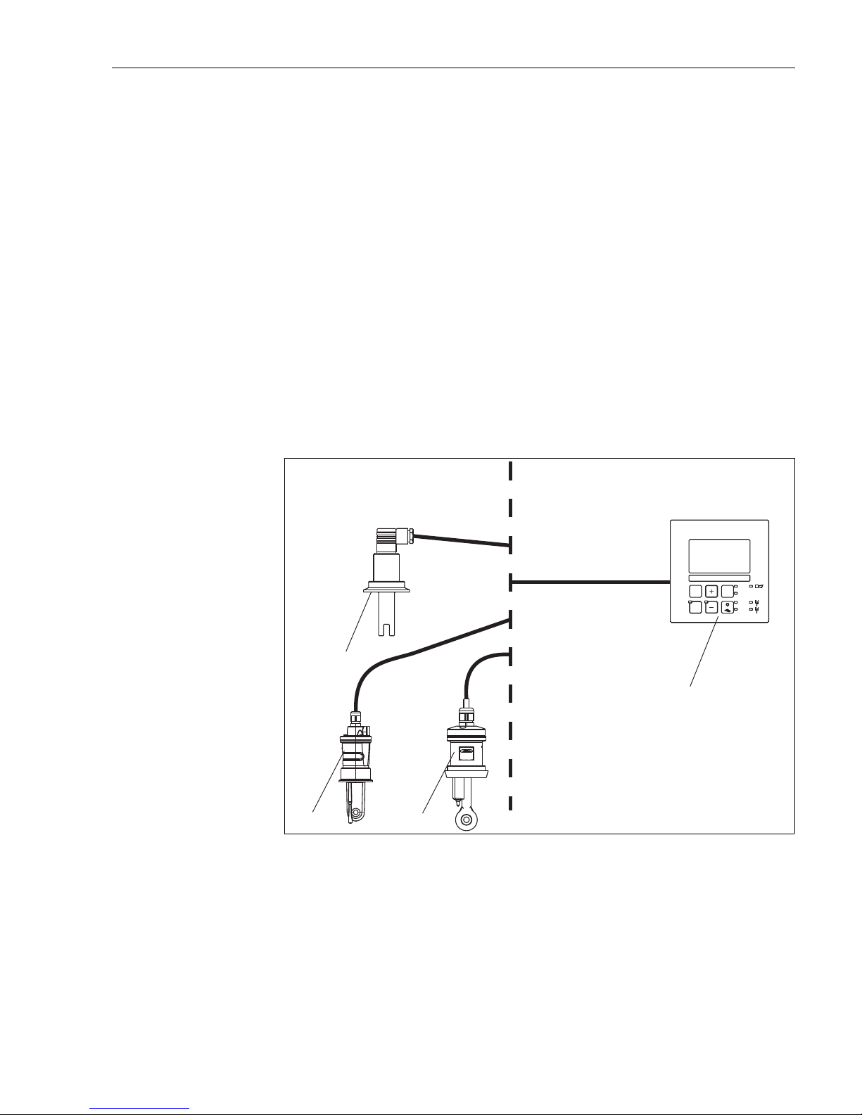
A complete measuring systems comprises:
• The transmitter Liquisys M CLM223 F
• A sensor with or without an integrated temperature sensor
• A measuring cable CYK71 (conductive) or CLK5 (inductive)
Options: extension cable, junction box VBM
a0003613
Fig. 1: Complete measuring system Liquisys CLM223 F
12Conductive sensor CLS21
Inductive sensor CLS54
34Inductive sensor CLS52
Liquisys M CLM223 F
CAL REL
REL1
REL1
ALARM
REL2
REL2
E
1
3
4
2
Page 10
Mounting Liquisys M CLM223F
10 Endress+Hauser
3.2 Installation conditions
a0005735
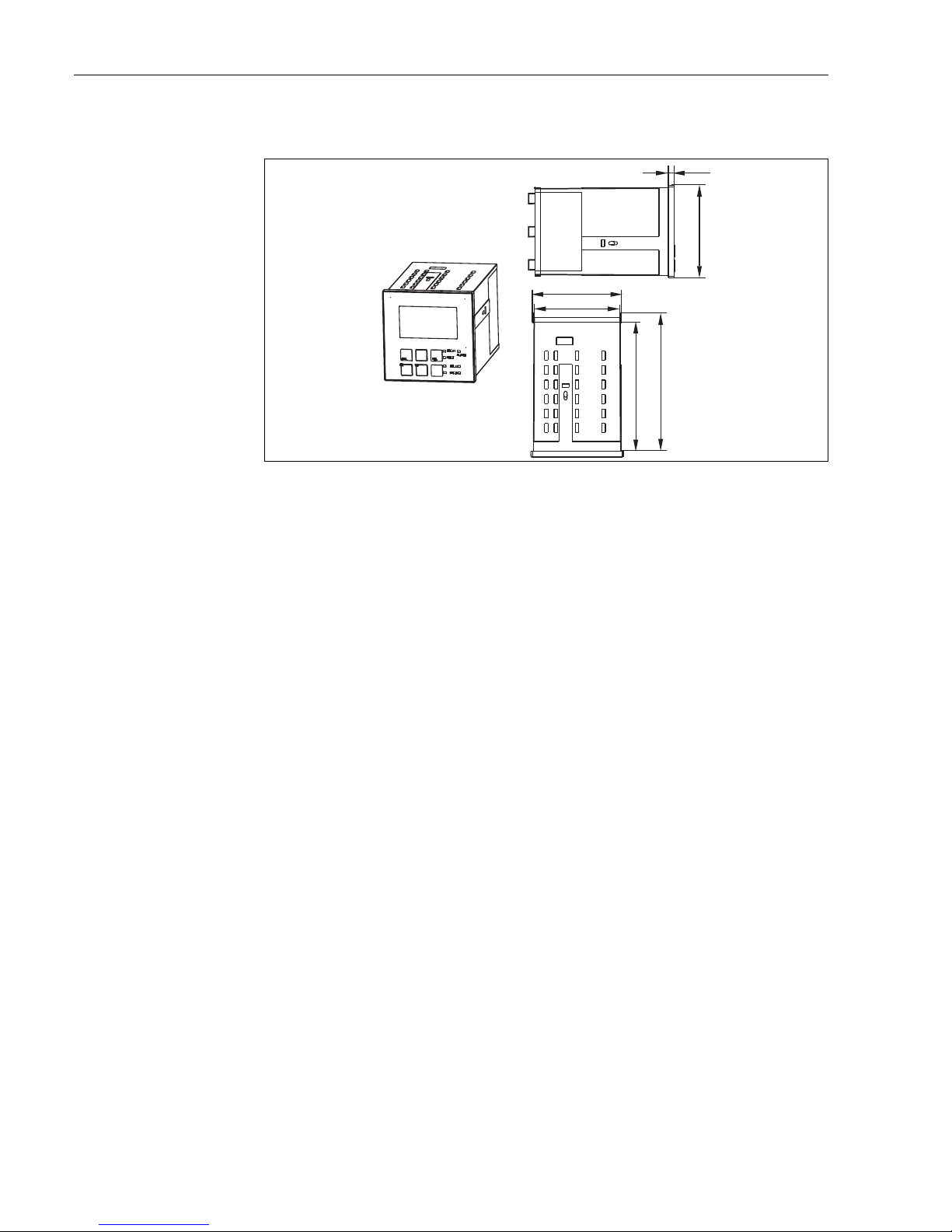
Fig. 2: Panel-mounted instrument
90 / 3.54
139 / 5.47
96 / 3.78
6/
0.24
mm / inch
92 / 3.62
149.5 / 5.89
Page 11
Liquisys M CLM223F Mounting
Endress+Hauser 11
3.3 Installation instructions
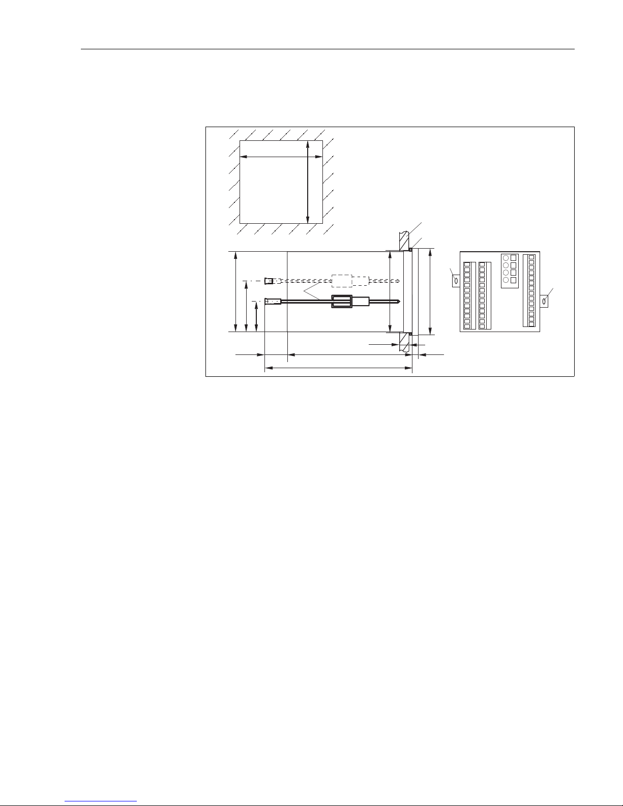
The panel-mounted instrument is secured with the clamping screws supplied (see å 3).
The necessary installation depth is approx. 165 mm (6.50").
a0005739
Fig. 3: Securing the panel-mounted instrument
1 Wall of the cabinet
2Seal
3 Clamping screws
* Required installation depth
3.4 Post-installation check
• After installation, check the transmitter for damage.
• Check whether the transmitter is protected against moisture and direct sunlight.
1
2
3
3
3
92 / 3.62
+0.5 +0.02
92 / 3.62
+0.5 +0.02
90 / 3.54
57 / 2.24
33 /
1.30
approx. 25 /
0.98
139 / 5.47
max. 45 /
1.77
6 /
0.24
96 / 3.78
92 /
3.62
approx. 165 / 6.50*
mm / inch
Page 12

Electrical connection Liquisys M CLM223F
12 Endress+Hauser
4 Electrical connection
WARNING
!
Device is energized
Improper connection can cause injury or death.
‣ The electrical connection must only be carried out by a certified electrician.
‣ Technical personnel must have read and understood the instructions in this manual and
must adhere to them.
‣ Prior to beginning any wiring work, make sure voltage is not applied to any of the cables.
4.1 Wiring
NOTICE
The device does not have a power switch
‣ You must provide a protected circuit breaker in the vicinity of the device.
‣ This must be a switch or a power-circuit breaker and you must label it as the circuit
breaker for the device.
‣ At the supply point, the power supply for the 24 V versions must be isolated from
dangerous live cables by double or reinforced insulation.
Page 13
Liquisys M CLM223F Electrical connection
Endress+Hauser 13
4.1.1 Connection diagram
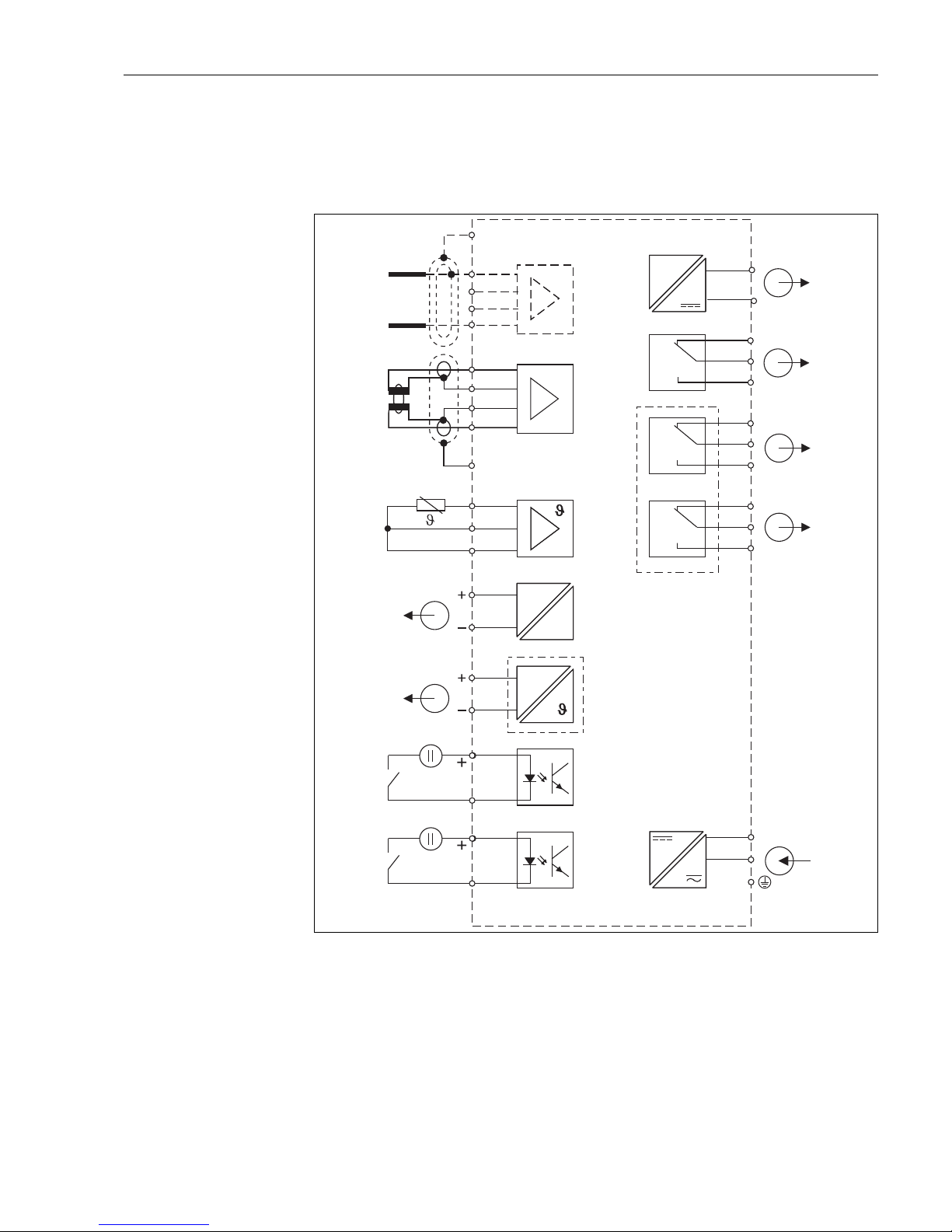
The wiring diagram depicted in å 4 shows the connections of an instrument equipped
with all the options. Connecting the sensors and the various measuring cables is explained
in more detail in the "Measuring cables and sensor connection" section.
a0003607
Fig. 4: Electrical connection of the transmitter
A
B
C
D
E
F
Sensor (conductive)
Sensor (inductive)
Temperature sensor
Signal output 1 conductivity
Signal output 2 temperature
Binary input 1 (MRS)
G
H
I
J
K
L
Binary input 2 (MRS)
Aux. voltage output
Alarm (current-free contact position)
Relay 1 (current-free contact position)
Relay 2 (current-free contact position)
Power supply
11
12
13
47
48
49
57
58
59
15 V
10-50 V
81
82
10-50 V
93
94
41
42
43
Lf
mA
31
32
mA
33
34
S
84
83
15
16
84
PE
83
L+
L–N
L1
~=
PE
15
16
85+
86
_
A
B
C
D
E
F
G
H
I
J
K
L
Page 14
Electrical connection Liquisys M CLM223F
14 Endress+Hauser
Pay attention to the following:
• The device is approved for protection class II and is generally operated without a protective
earth connection.
• To guarantee measuring stability and functional safety, you have to ground the outer
screen of the sensor cable:
– Inductive sensors: terminal "S"
– Conductive sensors: PE distributor rail
This is on the cover frame for panel-mounted instruments and in the connection
compartment for field devices. Ground the PE distributor rail or the ground terminal.
• The circuits "E" and "H" are not galvanically isolated from each other.
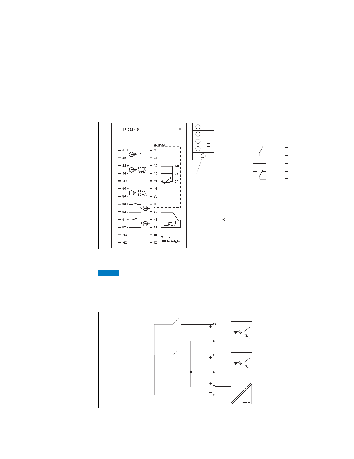
Panel-mounted instrument connection
a0003608
Fig. 5: Connection compartment sticker
NOTICE
Nonobservance could cause incorrect measurement
‣ Terminals marked NC may not be wired.
‣ Unmarked terminals may not be wired.
Power supply of binary inputs
a0003610
Fig. 6: Power supply of binary inputs
A Hold / MRS (for function "MRS 4 measuring ranges" switches are digital coded
REL1
REL2
REL3
REL4
NC
NC
49
COM
COM
COM
COM
59
54
55
56
52
51
53
58
57
48
47
131084-4B
Binary
Binary
1
15 V
85
86
81
82
93
94
A
A
Page 15
Liquisys M CLM223F Electrical connection
Endress+Hauser 15
4.1.2 Measuring cable and sensor connection
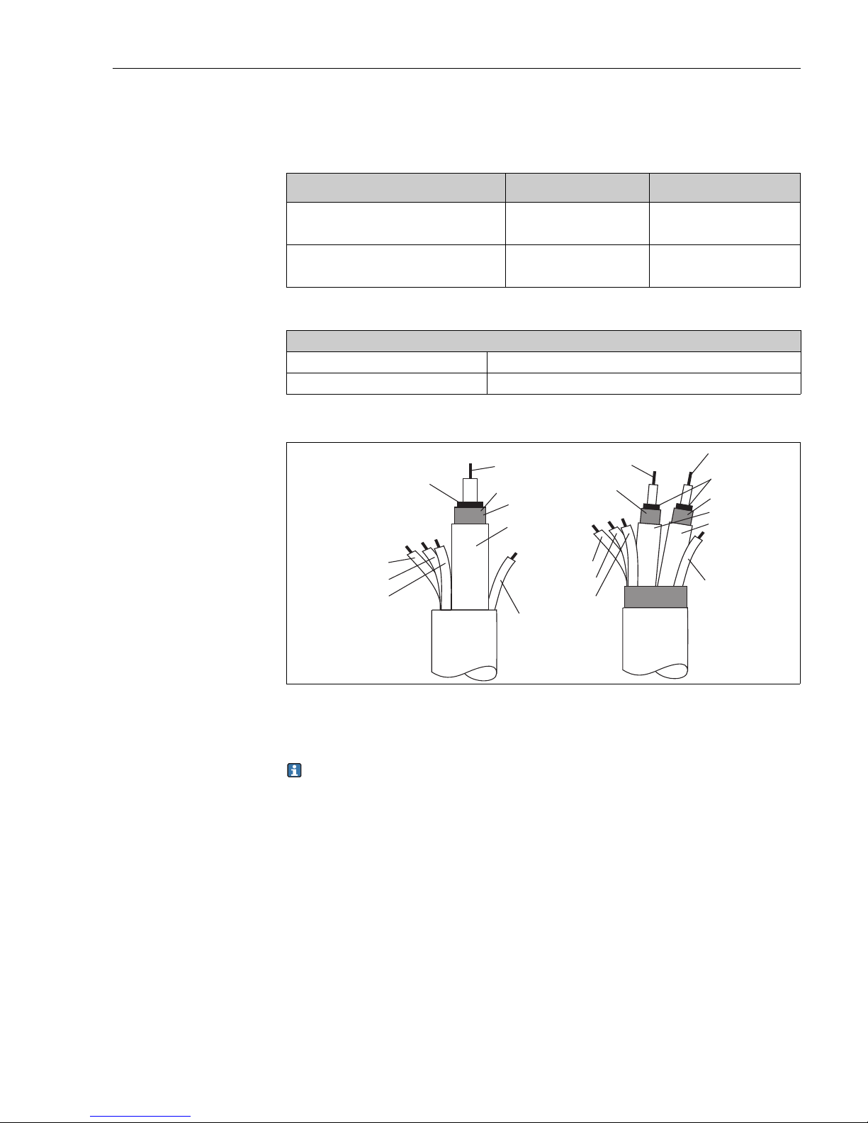
You require screened special measuring cables to connect conductivity sensors to the
transmitter. The following multi-core and ready-to-use cable types can be used:
Structure and termination of the measuring cables
C07-CLM2x3xx-04-06-00-de-004.eps
Fig. 7: Structure of the special measuring cables
A Semiconductor layer
sc Screening
For further information on the cables and junction boxes, please refer to the
"Accessories" section.
Sensor type Cable Extension
Two-electrode sensors with or without
temperature sensor Pt 100
CYK71 Junction box VBM + CYK71
Inductive sensors CLS50, CLS52, CLS54 Cable permanently attached
to sensor
Junction box VBM + CLK5
Maximum cable length
Conductivity measurement (conductive) max. 100 m (328 ft) with CYK71
Conductivity measurement (inductive) max. 55 m (180.46 ft) with CLK5 (sensor cable incl.)
83
84
11
12
13
CYK71
CLK5
15
16
83
84
11
12
13
A
GN
WH
YE
BK
sc
BN(nc)
GN
WH
YE
A
sc
WH
RD
BN(nc)
sc
Page 16
Electrical connection Liquisys M CLM223F
16 Endress+Hauser
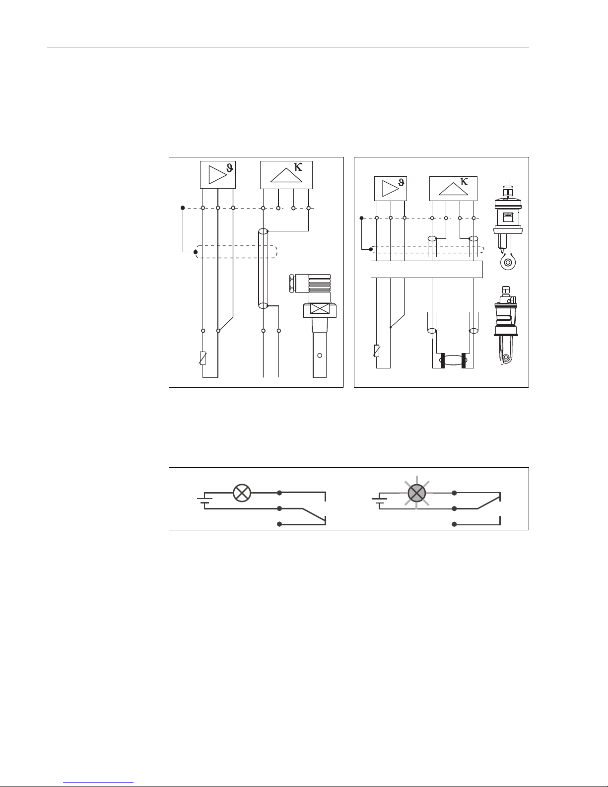
Measuring cable connection
To connect a conductivity sensor, connect the measuring cable in accordance with the
terminal assignment to the terminals on the rear of the device (see connection sticker).
Example of connecting a conductivity sensor
4.1.3 Alarm contact
C07-CLM2x3xx-04-06-00-xx-007.eps
Fig. 8: Connection of conductive sensors
a0006611
Fig. 9: Connection of inductive sensors
C07-CxM2x3xx-04-06-00-xx-001.eps
Fig. 10: Recommended fail-safe switching for the alarm contact
A Normal operating status B Alarm condition
Normal operating status:
• Device in operation
• No error message present
(Alarm LED off)
Relay energized
Contact 42/43 closed
Alarm condition
• Error message present (alarm LED red)
or
• Device defective or voltage-free (alarm LED
off)
Relay de-energized
Contact 41/42 closed
GN WH YE
GN WH YE
BK
BK
CYK71/CPK9
J
83 16 15 84
23 1
11 12 13
PE
RD WH
CLK 5
J
83 16 15 84
11 12 13
GN WH YE
BU RD RD BU
S
41
42
43
41
42
43
A
B
Page 17
Liquisys M CLM223F Electrical connection
Endress+Hauser 17
4.2 Post-connection check
After wiring up the electrical connection, carry out the following checks:
Device status and specifications Remarks
Are the transmitter or the cable externally damaged? Visual inspection
Electrical connection Remarks
Are the installed cables strain-relieved? Bracket joint for cable ties at the rear
plate
No loops and cross-overs in the cable run?
Are the signal cables correctly connected acc. to the wiring diagram?
Are all screw terminals tightened?
Are all cable entries installed, tightened and sealed?
Are the PE distributor rails grounded (present at version CF)? Grounding at place of installation
Page 18
Operability Liquisys M CLM223F
18 Endress+Hauser
5Operability
5.1 Display and operating elements
5.1.1 Display
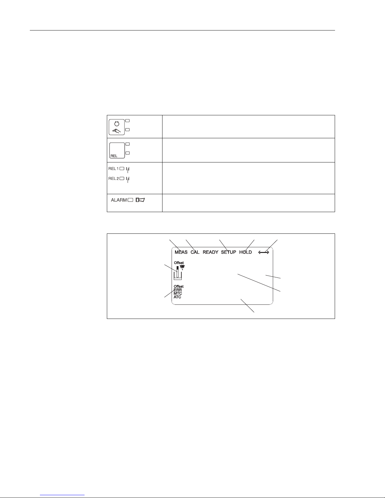
LED display
LC display
Indicates the current operating mode, "Auto" (green LED) or
"Manual" (yellow LED)
Indicates the activated relay in the "Manual" mode (red LED)
Indicates the working status of relay 1 and 2
LED green: measured value within the permitted limit, relay
inactive
LED red: measured value outside the permitted limit, relay active
Alarm display, e.g. for continuous limit value overshoot,
temperature sensor failure or system error (see error list)
a0003611-en
Fig. 11: LC display transmitter
1
2
3
4
5
Indicator for measuring mode (normal operation)
Indicator for calibration mode
Indicator for setup mode (configuration)
Indicator for "Hold" mode (current outputs remain
at last current state)
Indicator for receipt of a message for devices with
communication
6
7
8
9
10
Function code display
In measuring mode: measured variable
In setup mode: configured variable
In measuring mode: secondary measured value
In setup/calibr. mode: e.g. setting value
"Error": error display
Sensor symbol
REL 1
REL 2
9999
mS/cm
R2
1
23
4
5
6
7
8
9
10
On value
Page 19
Liquisys M CLM223F Operability
Endress+Hauser 19
5.1.2 Operating elements
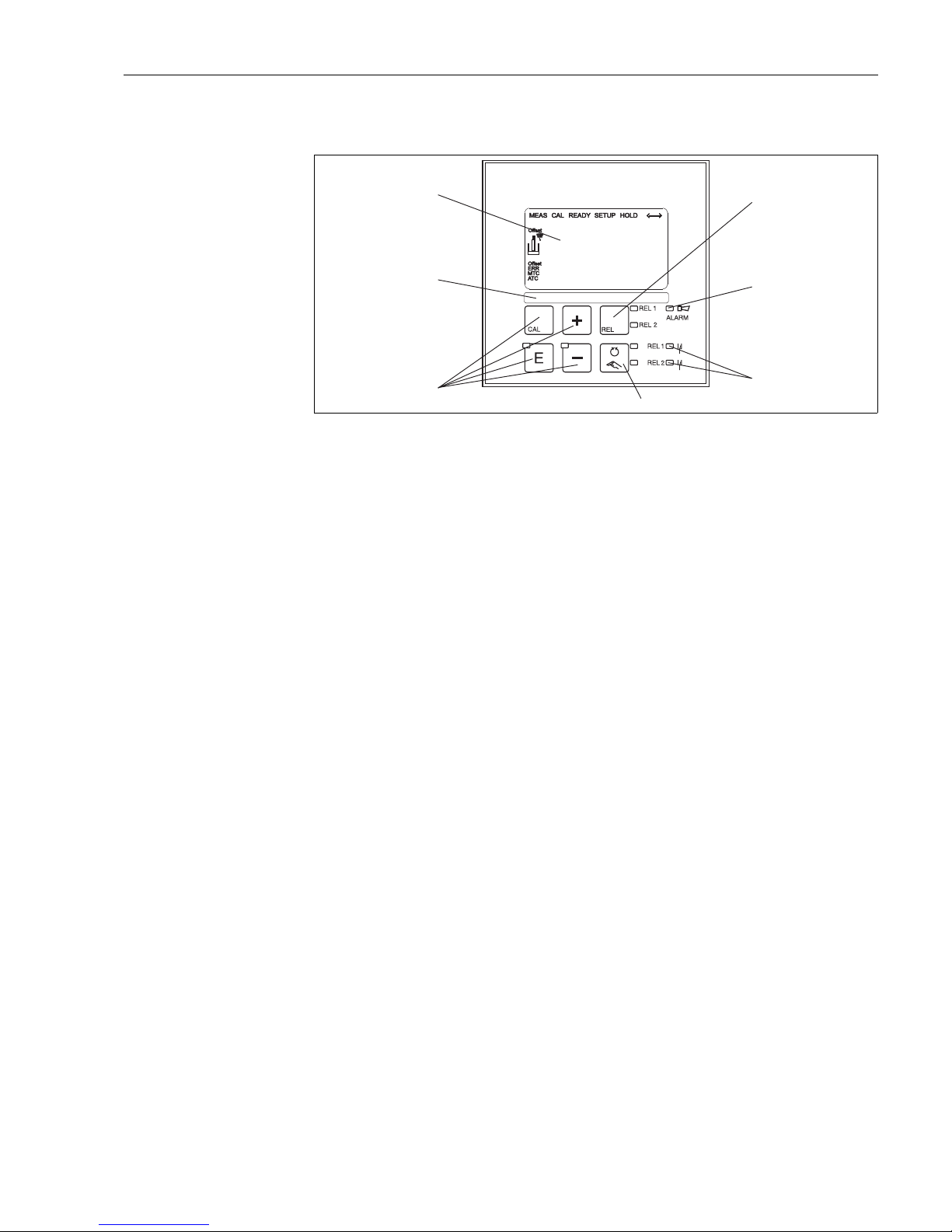
a0003609-en
Fig. 12: Operating elements
1 LC display for displaying the measured values and configuration data
2 Field for user labelling
3 4 main operating keys for calibration and device configuration
4 Changeover switch for automatic/manual mode of the relays
5 LEDs for limit contactor relay (switch status)
6 LED for alarm function
7 Display of the active contact and key for relay changeover in manual mode
9999
mS/cm
R2
1
2
3
4
5
6
7
On value
Page 20
Operability Liquisys M CLM223F
20 Endress+Hauser
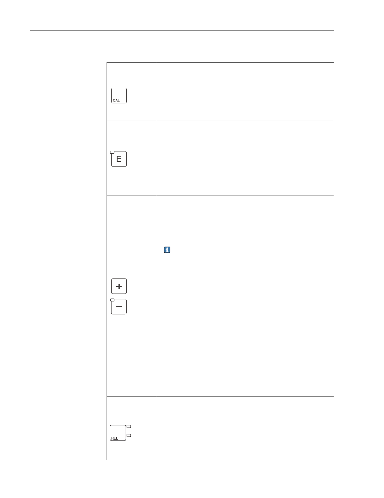
5.1.3 Key assignment
CAL key
When you press the CAL key, the device first prompts you for the
calibration access code:
• Code 22 for calibration
• Code 0 or any other code for reading the last calibration data
Use the CAL key to accept the calibration data or to switch from field
to field within the calibration menu.
ENTER key
When you press the ENTER key, the device first prompts you for the
setup mode access code:
• Code 22 for setup and configuration
• Code 0 or any other code for reading all configuration data.
The ENTER key has several functions:
• Calls up the Setup menu from the measuring mode.
• Saves (confirms) data entered in the setup mode.
• Moves on within function groups.
PLUS key and MINUS key
In the setup mode, the PLUS and MINUS keys have the following
functions:
• Selection of function groups.
Press the MINUS key to select the function groups in the order
given in the "System configuration" section.
• Configuration of parameters and numerical values
• Operation of the relay in manual mode
In the measuring mode, you get the following sequence of functions
by repeatedly pressing the PLUS key:
1. Temperature display in F
2. Temperature display hidden
3. Display of the uncompensated conductivity
4. Return to basic settings
In the measuring mode, the following is displayed in sequence by
repeatedly pressing the MINUS key:
1. Current errors are displayed in rotation (max. 10).
2. Once all the errors have been displayed, the standard
measurement display appears. In the function group F, an alarm
can be defined separately for each error code.
REL key
In the manual mode, you can use the REL key to switch between the
relay and the manual start of cleaning.
In the automatic mode, you can use the REL key to read out the
switch-on points assigned to the relay in question.
Press the PLUS key to jump to the settings of the next relay. Use the
REL key to get back to the display mode (automatic return after 30 s).
REL 1
REL 2
Page 21
Liquisys M CLM223F Operability
Endress+Hauser 21
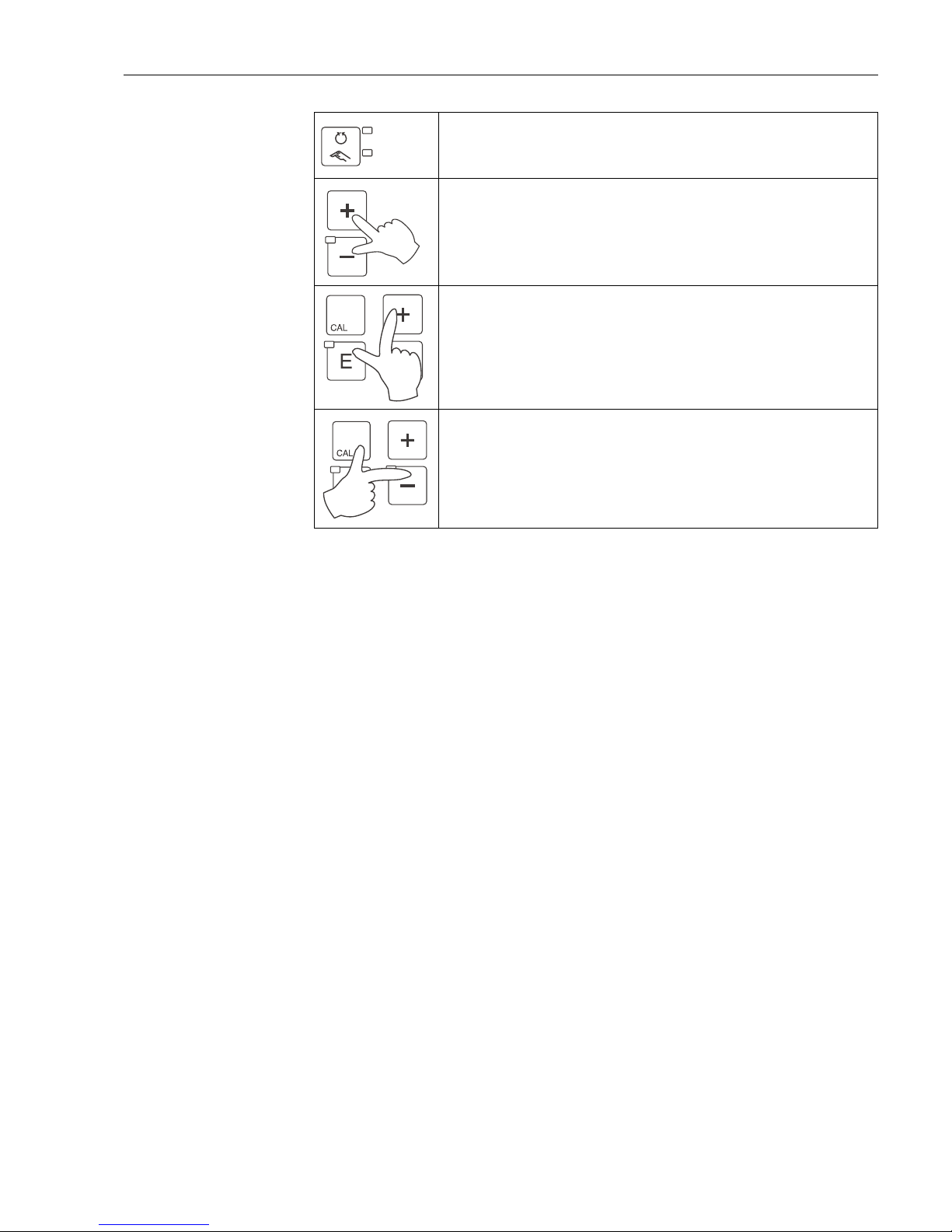
AUTO key
You can use the AUTO key to switch between automatic mode and
manual mode.
Escape function
If you press the PLUS and MINUS key simultaneously, you return to
the main menu or are taken to the end of calibration if calibrating. If
you press the PLUS and MINUS key again, you return to the
measuring mode.
Locking the keyboard
Press the PLUS and ENTER key for at least 3 s to lock the keyboard
against any unauthorized data entry. All the settings can continue to
be read.
The code prompt displays the code 9999.
Unlocking the keyboard
Press the CAL and MINUS key for at least 3 s to unlock the keyboard.
The code prompt displays the code 0.
Page 22
Operability Liquisys M CLM223F
22 Endress+Hauser
5.2 Local Operation
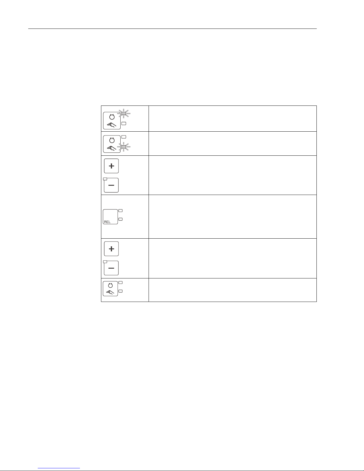
5.2.1 Automatic/manual mode
The transmitter normally operates in automatic mode. Here, the relays are triggered by the
transmitter. In the manual mode, you can trigger the relays using the REL key or start the
cleaning function.
How to change the operating mode:
Pay attention to the following:
• The selected operating mode remains in effect even after a power failure.
• The manual mode has priority over all automatic functions (Hold).
• Hardware locking is not possible in the manual mode.
• The manual settings are kept until they are actively reset.
• Error code E102 is signalled in the manual mode.
1. The transmitter is in Automatic mode. The top LED beside the
AUTO key is lit.
2. Press the AUTO key.
3. To enable the manual mode, enter the code 22 via the PLUS and
MINUS keys. The bottom LED beside the AUTO key lights up.
4. Select the relay or the function.
You can use the REL key to switch between the relays. The relay
selected and the switch status (ON/OFF) is displayed on the
second line of the display.
In the manual mode, the measured value is displayed continuously
(e.g. for measured value monitoring for dosing functions).
5. Switch the relay. It is switched on with PLUS and switched off with
MINUS.
The relay remains in its switched state until it is switched over
again.
6. Press the AUTO key to return to the measuring mode, i.e. to the
automatic mode. All the relays are triggered again by the
transmitter.
Page 23
Liquisys M CLM223F Operability
Endress+Hauser 23
5.2.2 Operating concept
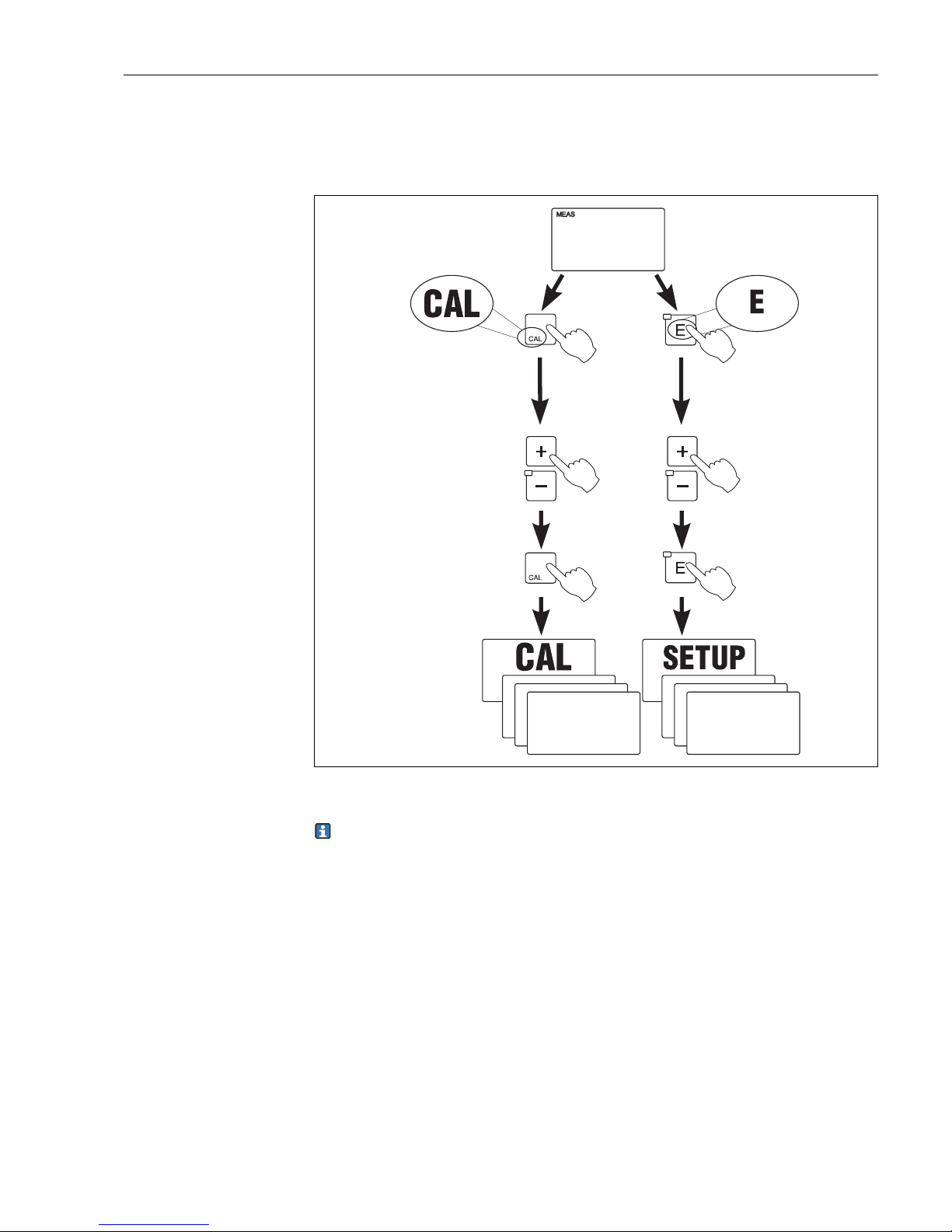
Operating modes
C07-CxM2x3xx-19-06-00-en-001.eps
Fig. 13: Description of the possible operating modes
If no key is pressed in the setup mode for approx. 15 min, the device automatically
returns to the measuring mode. Any active Hold (Hold during setup) is reset.
Access codes
All device access codes are fixed and cannot be altered. When the device requests the access
code, it distinguishes between different codes.
• Key CAL + Code 22: access to Calibration and Offset menu
• Key ENTER + Code 22: access to the setup menus
• Keys PLUS + ENTER: locks the keyboard
• Keys CAL + MINUS: unlocks the keyboard
• Key CAL or ENTER + any code: access to read mode, i.e. all the settings can be read but
not modified.
The device continues measuring in the read mode. It does not shift to the Hold status. The
current output and the controllers remain active.
Code
Measuring mode:
standard mode of
operation, displaying
current measured values
Setup mode
access to all
configuration
settings
Calibration mode:
execution of
calibration routine
The function groups
are selected with the
PLUS or MINUS key.
Page 24
Operability Liquisys M CLM223F
24 Endress+Hauser
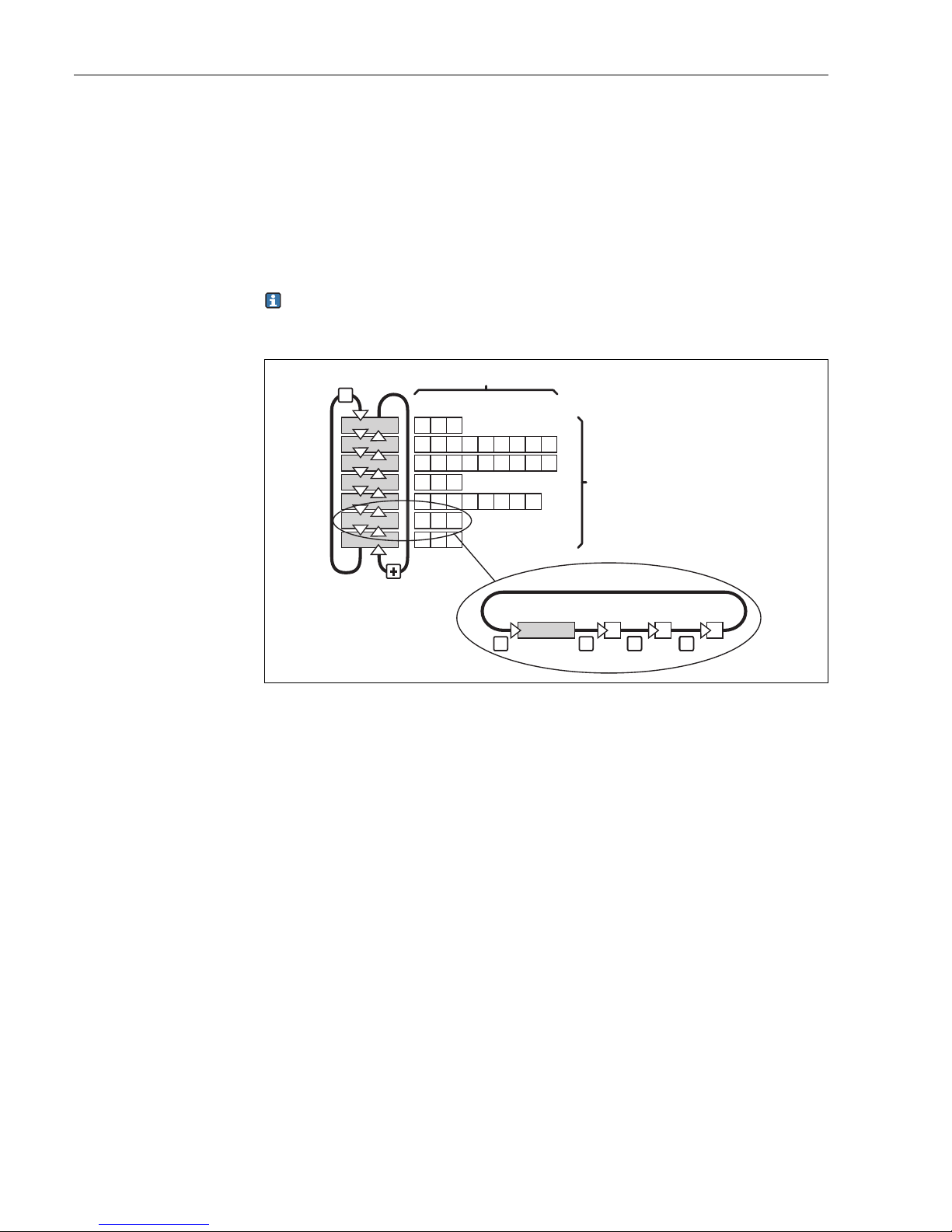
Menu structure
The configuration and calibration functions are arranged in function groups.
• In setup mode, select a function group with the PLUS and MINUS keys.
• In the function group itself, switch from function to function with the ENTER key.
• Within the function, select the desired option with the PLUS and MINUS keys or edit the
settings with these keys. Then confirm with the ENTER key and continue.
• Press the PLUS and MINUS keys simultaneously (Escape function) to exit programming
(return to the main menu).
• Press the PLUS and MINUS simultaneously keys again to switch to the measuring mode.
If a modified setting is not confirmed with ENTER, the old setting is retained.
An overview of the menu structure is provided in the Appendix to these Operating
Instructions.
C07-CxM2x3xx-19-06-00-xx-002.eps
Fig. 14: Diagram of the menu structure
1 Functions (parameters selected, numbers entered)
2 Function groups, scroll backwards and forwards with the PLUS and MINUS keys
3 Switch from function to function with the ENTER key
Hold function: "freezing" of the outputs
During setup and calibration, the current output can be "frozen". It constantly retains its
current status. "HOLD" appears on the display. If the controller actuating variable (steady
control 4 to 20 mA) is output via current output 2, it is set to 0/4 mA in Hold.
Pay attention to the following:
• Hold settings can be found in the "Service" section.
• During Hold, all contacts will go to their normal positions.
• An active Hold has priority over all other functions.
• With every Hold, the I-component of the controller is set to zero.
• Any alarm delay is reset to "0".
• This function can also be activated externally via the Hold input (see Wiring diagram;
binary input 1).
• The manual Hold (field S3) remains active even after a power failure.
EE E E
-
1
2
3
E
E
E
E
E
E
E
E
E
Page 25
Liquisys M CLM223F Commissioning
Endress+Hauser 25
6 Commissioning
6.1 Function check
WARNING
!
Incorrect connection, incorrect supply voltage
Safety risks for staff and incorrect operation of the device
‣ Check that all connections have been established correctly in accordance with the wiring
diagram.
‣ Make sure that the supply voltage matches the voltage indicated on the nameplate.
6.2 Switching on
Familiarize yourself with the operation of the transmitter before it is first switched on.
Please refer in particular to the "Safety instructions" and "Operation" sections.
After power-up, the device performs a self-test and then goes to the measuring mode.
Now calibrate the sensor in accordance with the instructions in the "Calibration" section.
During commissioning, the sensor must be calibrated so that the measuring system can
return precise measurement data.
Then perform the first configuration in accordance with the instructions in the "Quick startup" section. The values set by the user are kept even in the event of a power failure.
The following function groups are available in the transmitter (the groups only available in
the Plus Package are marked accordingly in the functional description):
Setup mode
•SETUP 1 (A)
•SETUP 2 (B)
• CURRENT OUTPUT (O)
•ALARM (F)
• CHECK (P)
•RELAY (R)
• TEMPERATURE COMPENSATION (T)
• CONCENTRATION MEASUREMENT (K)
• SERVICE (S)
• E+H SERVICE (E)
• INTERFACE (I)
• TEMPERATURE COEFFICIENT (D)
• MRS (M)
Calibration mode
• CALIBRATION (C)
A detailed explanation of the function groups available in the transmitter can be found
in the "System configuration" section.
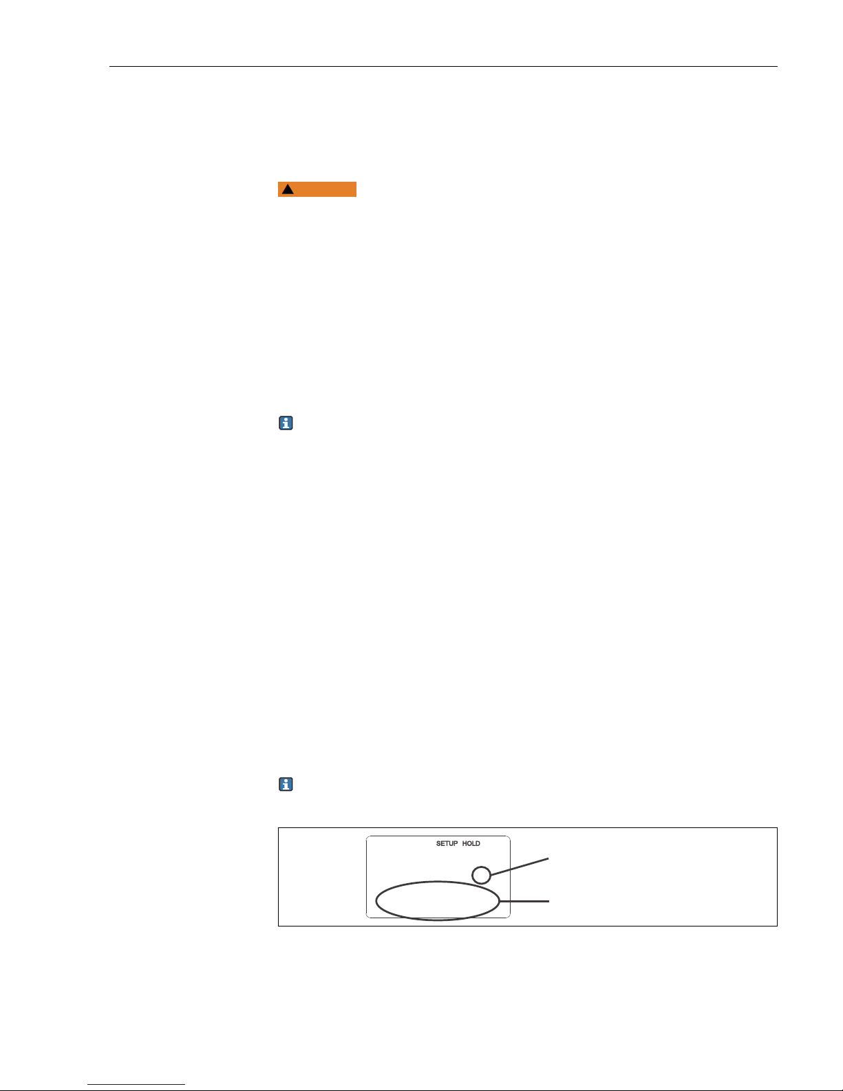
C07-CLD132xx-07-06-00-en-003.eps
Fig. 15: Example for display in setup mode
s
F3
Err.delay
Function display:
The displayed code indicates
the function position in the
function group.
Additional information
2
Page 26
Commissioning Liquisys M CLM223F
26 Endress+Hauser
Factory settings
The first time it is switched on, the device has the factory setting for all functions. The table
below provides an overview of the most important settings.
All other factory settings can be found in the description of the individual function groups in
the "System configuration" section (the factory setting is highlighted in bold).
* For corresponding version
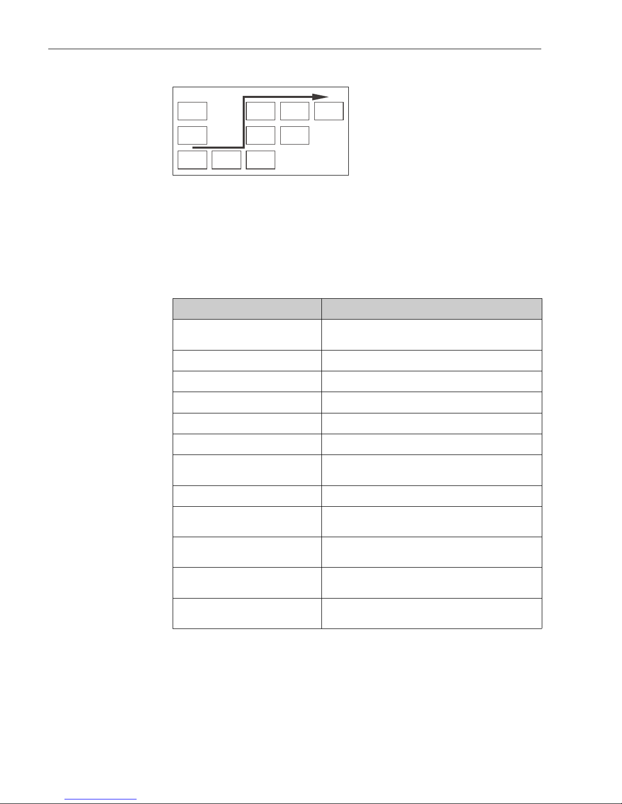
C07-CLD132xx-13-06-00-xx-005.eps
Fig. 16: Function coding
Selecting and locating functions is facilitated
by a code displayed for each function in a
special display field å 15.
The structure of this coding is given in
å 16.
The first column indicates the function
group as a letter (see group designations).
The functions in the individual groups are
counted from the top to the bottom and from
the left to the right.
Function Factory setting
Type of measurement Conductive conductivity measurement
Temperature measurement in °C
Type of measurement compensation Linear with reference temperature 25 °C (77 °F)
Temperature compensation Automatic (ATC on)
Limit value for controller 1 2000 mS/cm
Limit value for controller 2 2000 mS/cm
Hold Active during configuration and calibration
Measuring range 10 μS/cm to 2000 mS/cm (no measuring ranges for setting).
The setting is flowing and is guided by the connected sensors.
Current outputs 1* and 2* 4 ... 20 mA
Current output 1: measured value for 4
mA signal current*
0 μS/cm
Current output 1: measured value for 20
mA signal current*
2000 mS/cm
Current output 2: temperature value for 4
mA signal current*
0.0 °C (32 °F)
Current output 2: temperature value for
20 mA signal current*
150.0 °C (302 °F)
C C1 C111
C121
C131 C132 C133
Page 27
Liquisys M CLM223F Commissioning
Endress+Hauser 27
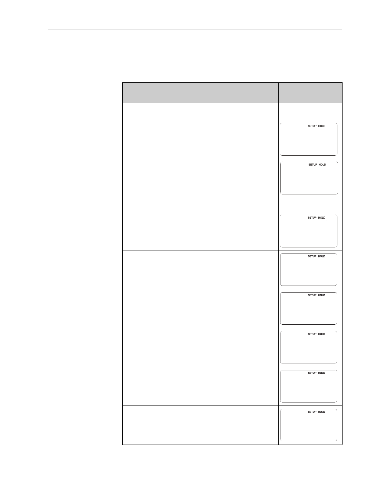
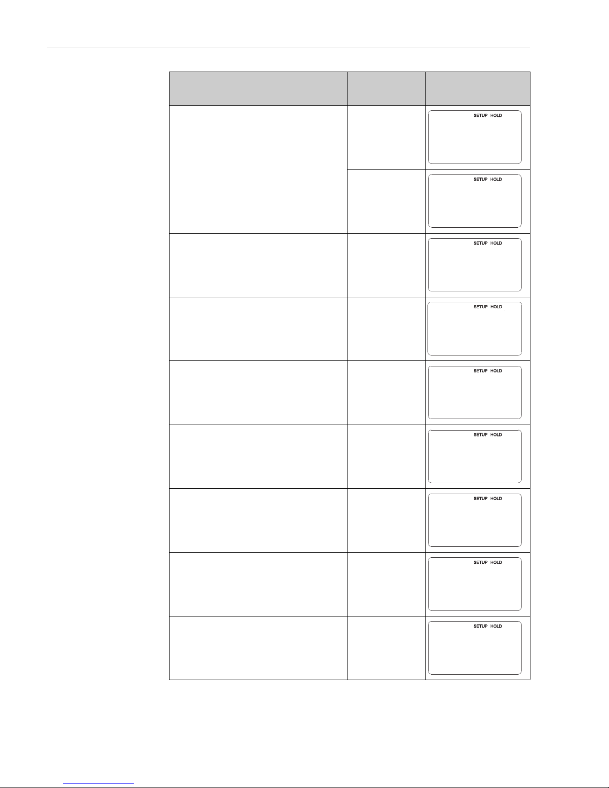
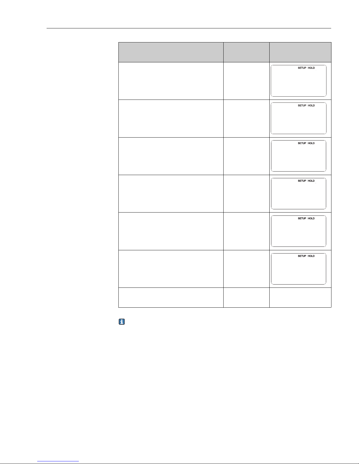
6.3 Quick start-up
After power-up, you must make some settings to configure the most important functions of
the transmitter which are required for correct measurement. The following section gives an
example of this.
User input Setting range
(Factory settings,
bold)
Display
1. Press the ENTER key.
2. Enter the code 22 to edit the setup. Press ENTER.
3. Press MINUS until you get to the "Service" function
group.
4. Press ENTER to be able to make your settings.
5. In S1, select your language, e.g. "ENG" for English.
Press ENTER to confirm.
ENG = English
GER = German
FRA = French
ITA = Italian
NEL = Dutch
ESP = Spanish
6. Press the PLUS and the MINUS keys
simultaneously to exit the "Service" function group.
7. Press MINUS until you get to the "Setup 1" function
group.
8. Press tENTER to be able to make your settings for
"Setup 1".
9. In A1, select the desired mode of operation, e.g.
"cond" = conductive.
Press ENTER to confirm.
cond = conductive
ind = inductive
10. In A2, press ENTER to confirm the factory
settings.
(if A1 = conc, else step 12)
%
ppm
mg/l
TDS = Total Dissolved
Solids
none
11. In A3, press ENTER to confirm the factory
settings.
XX.xx
X.xxx
XXX.x
XXXX
12. In A4, press ENTER to confirm the factory
settings.
auto, μS/cm, mS/cm,
S/cm, μS/m, mS/m,
S/m
13. In A5, enter the cell constant of the connected
sensor.
Refer to the sensor’s quality certificate for the
exact value.
0.0025 ... 5.9 ... 99.99
S
SERVICE
S1
Language
ENG
A
SETUP 1
A1
Oper.Mode
cond
A2
Conc.Unit
%
A3
Format
XX.xx
A4
Unit
auto
5.900
A5
1/cm
Cellconst
Page 28
Commissioning Liquisys M CLM223F
28 Endress+Hauser
14. In A6, enter the resistance of the cable
(conductive sensors only)
or
enter the installation factor (inductive sensors
only).
0
0 to 99.99
0.10 to 1 to 5.00
15. If you need to stabilise the display, enter the
required damping factor in A7.
Press ENTER to confirm.
The display returns to the initial display of "Setup
1"
1
1 to 60
16. Press MINUS to go to the "Setup 2" function group
17. Press ENTER to edit "Setup 2"
18. In B1, select your temperature sensor.
Press ENTER to confirm.
Pt 100
Pt 1k = Pt 1000
NTC30
fixed
19. In B2, select the appropriate temperature
compensation for your process, e.g. "lin" = linear.
Press ENTER to confirm your selection.
For detailed information on temperature
compensation, see chapter "Setup 2"
lin = linear
Tab = Tabelle 1 to 4
NaCl = common salt
(IEC 60746)
none
20. In B3, enter the temperature coefficient .
Press ENTER to confirm.
2.1 %/K
0.0 to 20.0 %/K
21. The real temperature is displayed in B5. If
necessary, calibrate the temperature sensor to an
external measurement.
Press ENTER to confirm.
Display and entry of
real temperature
-10.0 to 150.0 °C
fixed
22. The difference between the measured and the
entered temperatures is displayed.
Press ENTER.
The display returns to the initial display of the
"Setup 2" function group.
0.0 °C
-5.0 to 5.0 °C
User input Setting range
(Factory settings,
bold)
Display
Cable-Res
A6
0
@
A6
1.00
InstFac
A7
Damping
1
B
SETUP 2
B1
ProcTemp.
Pt100
B2
TempComp.
lin
B3
%/K
Alpha val
2.10
B5
C
°
RealTemp.
0.0
B6
C
°
TempOffs.
0.0
Page 29
Liquisys M CLM223F Commissioning
Endress+Hauser 29
For inductive sensors you must perform an airset before installation of the sensor, refer
to the chapter "Calibration"
23. Press MINUS to go to the "Current output" function
group.
24. Press ENTER to edit the output settings.
25. In O1, select your output, e.g. "Out1" = output 1.
Press ENTER to confirm.
Out1
Out2
26. In O2, select the linear characteristic.
Press ENTER to confirm.
lin = linear (1)
sim = simulation
27. In O211, select the current range for your output,
e.g. 4 to 20 mA.
Press ENTER to confirm.
4 to 20 mA
0 to 20 mA
28. In O212, enter the conductivity corresponding to
the minimum current value at the transmitter
output, e.g. 0 μS/cm.
Press ENTER to confirm.
cond/ind: 0.00 μS/cm
Conc: 0.00 %
Temp: 0.00 °C
29. In O213, enter the conductivity corresponding to
the maximum current value at the transmitter
output, e.g. 2000 mS/cm.
Press ENTER to confirm.
The display returns to the initial display of the
"Current output" function group.
cond/ind: 2000 mS/
cm
Conc: 99.99 %
Temp: 150 °C
30. Press the MINUS and the PLUS keys
simultaneously to switch to the measurement
mode.
User input Setting range
(Factory settings,
bold)
Display
O
OUTPUT
O1
Sel.Out
Out1
O2
lin
Sel. Type
O211
4-20
Sel.Range
O212
0.00
µS/cm
0/4 mA
O213
2000
mS/cm
20 mA
Page 30
Commissioning Liquisys M CLM223F
30 Endress+Hauser
6.4 System configuration
6.4.1 Setup 1 (Conductivity)
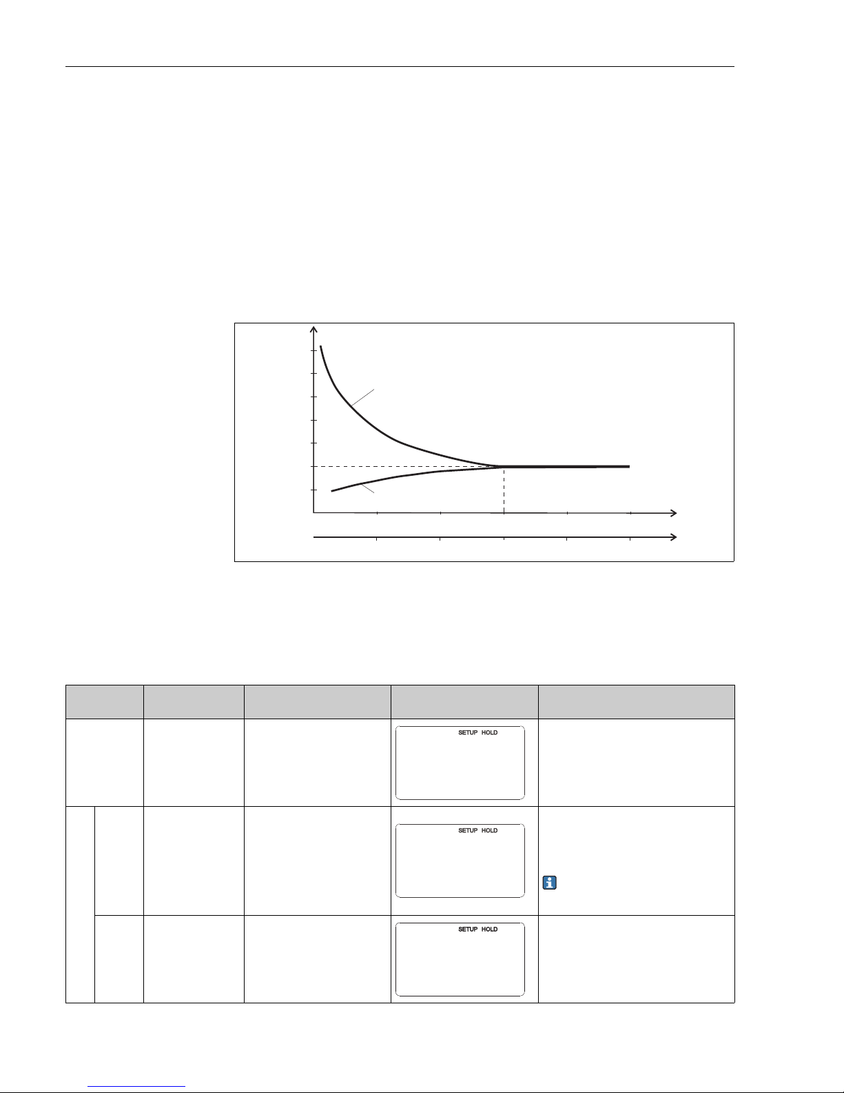
Wall distance
The sensor’s distance from the pipe wall affects the measuring accuracy ( å 17).
In narrow installation conditions, the ion flow in the medium is affected by the pipe walls.
This effect is compensated by the so-called installation factor.
When the distance from the wall is sufficient, i.e. a > 15 mm / 0.59", the installation factor
can be ignored (f = 1.00). When the wall distance is lower, the installation factor increases
in the case of electrically insulating pipes (f > 1) while it decreases for electrically conductive
pipes (f < 1); å 17.
The determination of the installation factor is described in the chapter "Calibration".
a0005441
Fig. 17: Relationship between installation factor and distance from wall a
1 Electrically conductive pipe wall
2 Insulating pipe wall
In the SETUP 1 function group, you can change the operating mode and the sensor settings.
Basic version does not include functions in italic.
1
2
a [inch]
0
5
10 15
20
2525
a [mm]
0.80
1.00
1.20
1.40
f
0.20
0.39
0.59
0.79
0.98
Coding Field Selection or range
(factory settings bold)
Display Info
A
Function group
SETUP 1
Basic settings.
A1
Select operating
mode
cond = conductivity
conc = concentration
Display varies depending on instrument
version:
–cond
–conc
Any change in operating mode
causes an automatic reset of user
settings.
A2
Select concentration
unit to be displayed
(only with Plus
Package)
%
ppm
mg/l
TDS = Total Dissolved Solids
none
A2 only active if A1 = conc.
A
SETUP 1
A1
Oper.Mode
cond
A2
Conc.Unit
%
Page 31
Liquisys M CLM223F Commissioning
Endress+Hauser 31
A3
Select display format
for concentration
unit
XX.xx
X.xxx
XXX.x
XXXX
A3 only active if A1 = conc.
A4
Select unit to be
displayed
auto, μS/cm, mS/cm, S/cm, μS/
m, mS/m, S/m
When “auto” is selected, the maximum
resolution possible is automatically
selected.
A4 not active if A1 = conc.
A5
Enter cell constant
for connected sensor
0.0025 to 5.9 to 99.99 cm
-1
For the exact value of the cell constant,
refer to the quality certificate.
A6
Conductive:
Enter cable
resistance
0
0 to 99.99
Only with conductive sensors. Multiply the
standardised line resistance by the actual
cable length.
CYK71: 0.165 /m
Inductive:
Enter installation
factor
0.10 to 1 to 5.0
This is where the installation factor is
edited. The correct factor is determined in
C1(3), see chapter "Calibration" or referring
to the installation factor diagram.
A7
Enter measured
value damping
1
1 to 60
Measured value damping causes averaging
over the specified number of individual
measured values. It is used, for example, to
stabilise the display with applications that
fluctuate a great deal.
There is no damping if “1” is entered.
Coding Field Selection or range
(factory settings bold)
Display Info
A3
Format
XX.xx
A4
Unit
auto
5.900
A5
1/cm
Cellconst
Cable-Res
A6
0
@
A6
1.00
InstFac
A7
Damping
1
Page 32
Commissioning Liquisys M CLM223F
32 Endress+Hauser
6.4.2 Setup 2 (Temperature)
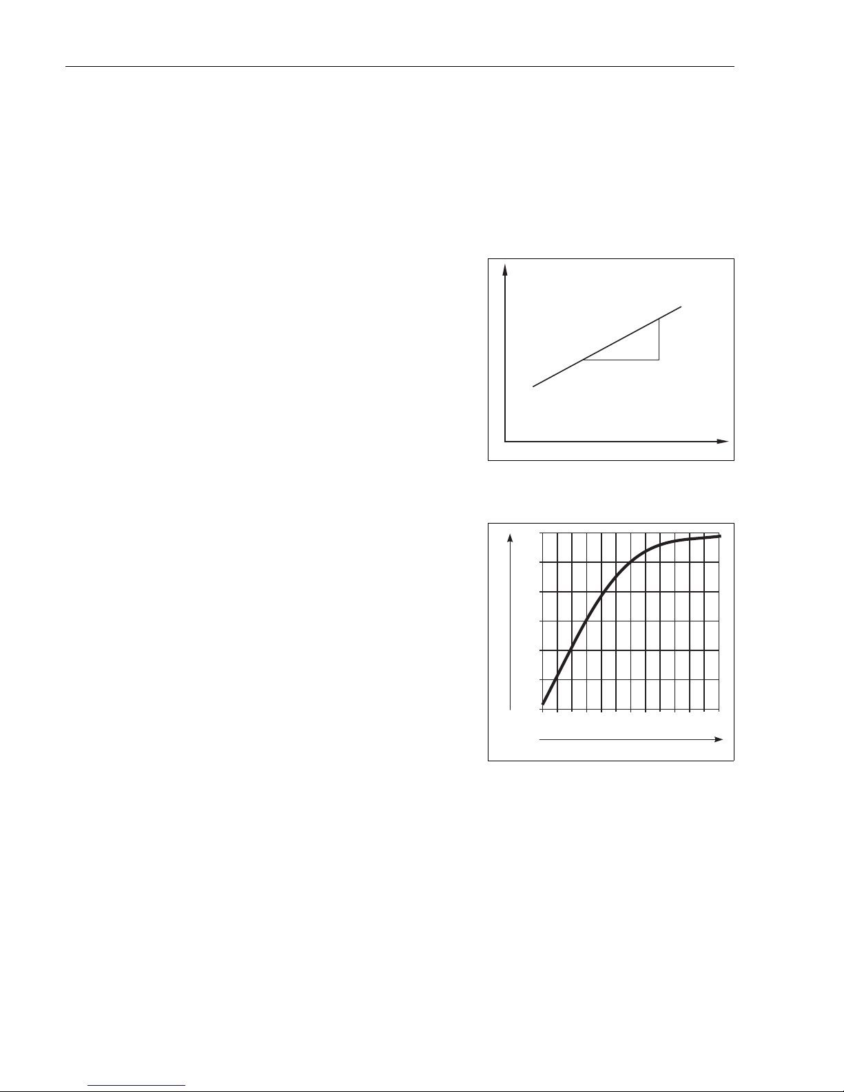
The temperature coefficient specifies the change in conductivity per degree of temperature
change. It depends on the chemical composition of the medium and the temperature itself.
In order to compensate for this dependence, four different compensation types can be
selected in the transmitter:
• Linear temperature compensation
• NaCl compensation
• Temperature compensation with table
Linear temperature compensation
The change between two temperature points
is considered to be constant, i.e. =const.
The value can be edited for the linear
compensation type. You can edit the
reference temperature in field B7, the factory
setting is 25 °C (77 °F).
C07-CLD132xx-05-06-00-xx-009.ep s
Fig. 18: Linear temperature compensation
* uncompensated conductivity
NaCl compensation
The NaCl compensation (according to IEC
60746) is based on a fixed nonlinear curve
that defines the relationship between the
temperature coefficient and the temperature.
This curve is used for lower concentrations of
up to approx. 5 % NaCl.
C07-CLD132xx-05-06-00-xx-010.ep s
Fig. 19: NaCl compensation
1
a
T
k*
0
48
96
144
2,1
2,3
2,5
2,7
T [°C]
a [%/K]
Page 33
Liquisys M CLM223F Commissioning
Endress+Hauser 33
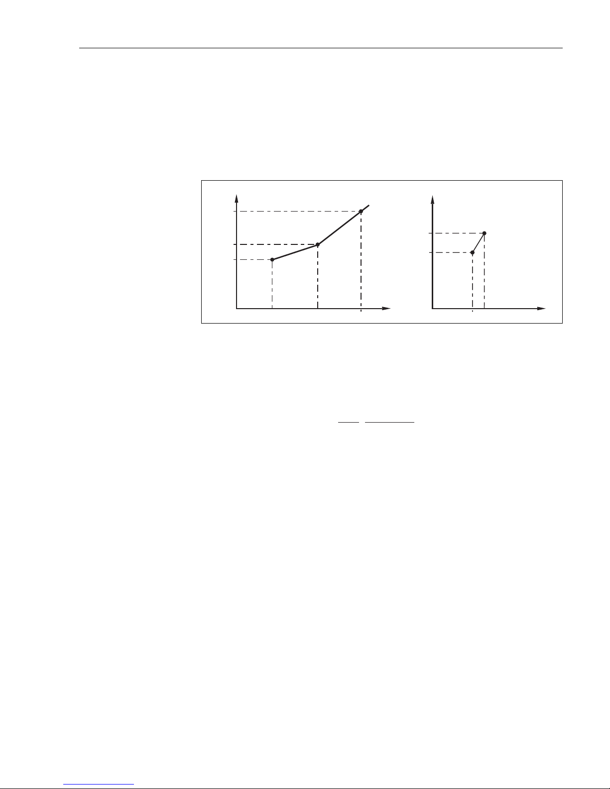
Temperature compensation with table
In case of transmitter with Plus package you can enter a table with temperature coefficients
in relation to temperature. When using the alpha table function for temperature
compensation, the following conductivity data of the process medium to be measured is
required:
Value pairs of temperature T and conductivity with:
• (T
0
) for the reference temperature T
0
• (T) for temperatures which occur in the process
C07-CLM153xx-05-06-00-xx-003.eps
Fig. 20: Determination of temperature coefficient
ARequired data
BCalculated
values
Use the following formula to calculate the values for the temperatures occurring in your
process:
Enter the T value pairs calculated with this formula in the fields T5 and T6 of the function
group "ALPHA TABLE".
T
1
T
0
T
2
TT
k
2
k
1
k()
T
0
T1T
2
a
1
a
2
a
A
B
a =
100%
k(T )
0
kk(T) - (T )
0
T - T
0
.
; T T¹
0
Page 34
Commissioning Liquisys M CLM223F
34 Endress+Hauser
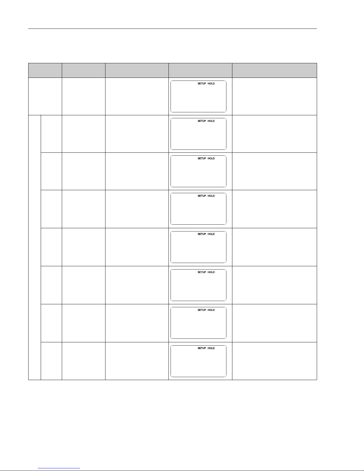
In the SETUP 2 function group, you can change the settings for temperature measurement.
Basic version does not include functions in italic.
Coding Field Selection or range
(factory settings bold)
Display Info
B
Function group
SETUP 2
Settings for temperature measurement.
B1
Select temperature
sensor
Pt100
Pt1k = Pt 1000
NTC30
fixed
If set to "fixed":
Manual temperature compensation (MTC),
no temperature measurement if fixed
temperature value is specified in B4. No
temperature output if "fixed"!
B2
Select temperature
compensation type
none
lin = linear
NaCl = common salt
(IEC 60746)
Tab = table
This option is not displayed for
concentration measurement.
B3
Enter temperature
coefficient
2.10 %/K
0.00 to 20.00 %/K
Only if B2 = lin.
With other settings in B2, field B3 has no
influence.
B4
Enter process
temperature
25 °C
-10.0 to 150.0 °C
Only if B1 = fixed.
This value can only be specified in °C.
B5
Display temperature
and calibrate
temperature sensor
Display and entry of real
temperature
-15.0 to 150.0 °C
This entry is used to calibrate the
temperature sensor to an external
measurement. Effects B6.
Omitted if B1 = fixed.
B6
Enter temperature
difference (offset)
Curent offset
-5.0 to 5.0 °C
The offset is the difference between the
entered actual value and the measured
temperature.
Omitted if B1 = fixed.
B7
Enter reference
temperature
25 °C
-35.0 to 250 °C
B
SETUP 2
B1
ProcTemp.
Pt100
B2
TempComp.
lin
B3
%/K
Alpha val
2.10
B4
C
°
ProcTemp.
25.0
B5
C
°
RealTemp.
0.0
B6
C
°
TempOffs.
0.0
B7
C
°
ref temp.
25.0
Page 35
Liquisys M CLM223F Commissioning
Endress+Hauser 35
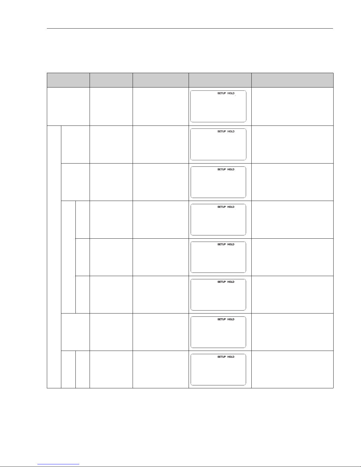
6.4.3 Current outputs
In the function group "Current output" you can configure the outputs. To check the outputs
you can simulate a current output value (O2 (2)).
Coding Field Setting range
(Factory settings, bold)
Display Info
O
CURRENT OUTPUT
function group
Configuration of the current output.
O1 Select current output
Out1
Out 2
A characteristic can be selected for every
output.
O2 (1)
Enter or output
linear characteristic
Lin = linear (1)
Sim = simulation (2)
The characteristic can have a positive or
negative slope for the measured value
output.
O211 Select current range
4 to 20 mA
0 to 20 mA
O212
0/4 mA value:
Enter corresponding
measured value
cond/ind: 0.00 μS/cm
Conc: 0.00 %
Temp: 0.0 °C
Here you can enter the measured value at
which the min. current value (0/4 mA) is
applied at the transmitter output.
(Spreading: see Technical data.)
O213
20 mA value:
Enter corresponding
measured value
cond/ind: 2000 mS/cm
Conc: 99.99 %
Temp: 150 °C
Here you can enter the measured value at
which the max. current value (20 mA) is
applied at the transmitter output.
(Spreading: see Technical data.)
O2 (2)
Simulate current
output
Lin = linear (1)
Sim = simulation (2)
Simulation is not ended until (1) or (3) is
selected.
O221
Enter simulation
value
Current value
0.00 to 22.00 mA
Entering a current value results in this
value being directly output at the current
output.
O
OUTPUT
O1
Sel.Out
Out1
O2
lin
Sel. Type
O211
4-20
Sel.Range
O212
0.00
µS/cm
0/4 mA
O213
2000
mS/cm
20 mA
O2
sim
Sel. Type
O221
4.00
mA
Simulat.
Page 36
Commissioning Liquisys M CLM223F
36 Endress+Hauser
6.4.4 Alarm
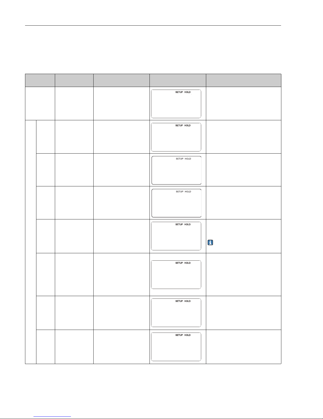
In the ALARM function group, you can define various alarms and configure output contacts.
Each individual error can be defined to be effective or not (at the contact or as an error
current).
Coding Field Setting range
(Factory settings, bold)
Display Info
F
ALARM function
group
Alarm function settings.
F1 Select contact type
Latch = latching contact
Momen = momentary contact
The contact type selected only applies to
the alarm contact.
F2 Select time unit
min
s
F3 Enter alarm delay
0 min (s)
0 to 2000 min (s)
Depending on the option selected in F2,
the alarm delay is entered in s or min.
F4 Select error current
22 mA
2.4 mA
This selection must be made even if all
error reporting is switched off in F5.
If "0-20 mA" was selected in O211,
"2.4 mA" may not be used.
F5 Select error
1
1 to 255
Here you can select all the errors which
should trigger an alarm.
The errors are selected via the error
numbers. Please refer to the table in
section "System error messages" for the
meaning of the individual error numbers.
The factory settings remain in effect for all
errors not edited.
F6
Set alarm contact to
be effective for the
selected error
yes
no
If “no” is selected, all other alarm settings
are deactivated (e.g. alarm delay). The
settings themselves are retained.
This setting only applies to the error
selected in F5.
Factory setting is no starting with E080!
F7
Set error current to
be effective for the
selected error
no
yes
The option selected in F4 is effective or
ineffective in the event of an error.
This setting only applies to the error
selected in F5.
F
ALARM
F1
Cont.Type
Latch
F2
Time Unit
min
F3
min
Err.Delay
0
F4
Err.Curr
22mA
F5
Sel.error
1
F6
Rel.Assg
yes
F7
Curr.Assg
no
Page 37

Liquisys M CLM223F Commissioning
Endress+Hauser 37
6.4.5 Check
Polarisation detection
Polarisation effects in the interface between sensor and measuring solution limit the
measuring range of conductive conductivity sensors. The transmitter has the ability to detect
polarisation effects using an intelligent evaluation process. Error code E071 will be
generated.
PCS alarm (Process Check System)
This function (field P2) is used to check measuring signals for deviations. If the measuring
signal is constant during the selected time frame, an alarm (E152) is triggered. The reason
for such sensor behaviour can be contamination, cable rupture or similar.
C07-CxM2x3xx-05-06-00-xx-001.eps
Fig. 21: PCS alarm (live check)
A Constant measuring signal = alarm triggered after PCS alarm time has elapsed
Any PCS alarm pending is automatically deleted as soon as the sensor signal changes.
F8
Select return to
menu or next error
next = next error
R
If R is selected, you return to F, if next is
selected, you go to F5.
Coding Field Setting range
(Factory settings, bold)
Display Info
F8
Select
next
A
t
Coding Field Setting range
(Factory settings, bold)
Display Info
P
CHECK function
group
Settings for sensor and process monitoring
P1
Switch polarisation
detection on or off
(conductive only)
Off
On
Polarisation only occurs with conductive
sensors.
Polarisation is detected, but not
compensated.
(error no.: E071)
P2
Set PCS Alarm
(live check)
off
1 h
2 h
4 h
Alarm signalling optionally with or
without simultaneous controller switchoff.
XXXX = without controller switch-off
XXXX! = with controller switch-off
(error no.: E152)
P
CHECK
P1
Pol.Detec
Off
P2
PCS alarm
off
Page 38
Commissioning Liquisys M CLM223F
38 Endress+Hauser
6.4.6 Relay contact configuration
To use the RELAY function group you need a relay board which is not part of the basic
version.
Limit contactor for measured conductivity value and temperature
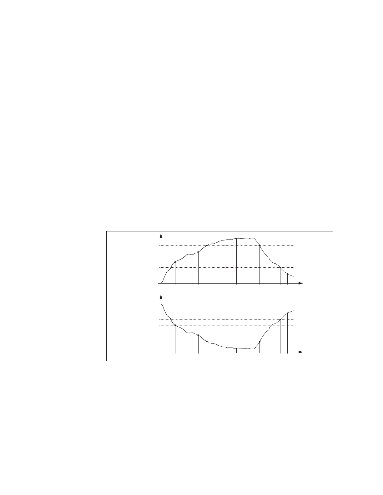
The transmitter has different ways of assigning a relay contact.
Switch-on and switch-off points and pick-up and drop-out delays can be assigned to the limit
contactor. In addition, you can configure an alarm threshold to output an error message and
to start a cleaning function in conjunction with this.
These functions can be used both for conductivity measurement and for temperature
measurement.
Please refer to Fig. 22 for a clear illustration of the relay contact states.
• When the measured values increase (maximum function), the relay contact is closed as of
t
2
after the switch-on point (t1) has been overshot and the pick-up delay has elapsed
(t
2-t1
).
The alarm contact switches if the alarm threshold (t
3
) is reached and the alarm delay
(t
4-t3
) (field F3) has also elapsed.
• When the measured values decrease, the alarm contact is reset when the alarm threshold
(t
5
) is undershot as is the relay contact (t7) after the drop-out delay (t7-t6).
• If the pick-up and drop-out delays are set to 0 s, the switch-on and switch-off points are
also switch points of the contacts.
Settings can also be made for a minimum function in the same way as for a maximum
function.
C07-CxM2x3xx-05-06-00-xx-003.eps
Fig. 22: Illustration of the alarm and limit value functions
ABSwitch-on point > switch-off point: Max. function
Switch-on point < switch-off point: Min. function12
3
4
Alarm threshold
Switch-on point
Switch-off point
Contact ON
5
6
7
Alarm ON
Alarm OFF
Contact OFF
t
1
t
1
t
2
t
2
t
3
t
3
t
4
t
4
t
5
t
5
t
6
t
6
t
7
t
7
t
t
B
1
2
3
3
2
1
4
5
6
7
4
5
6
7
A
Page 39
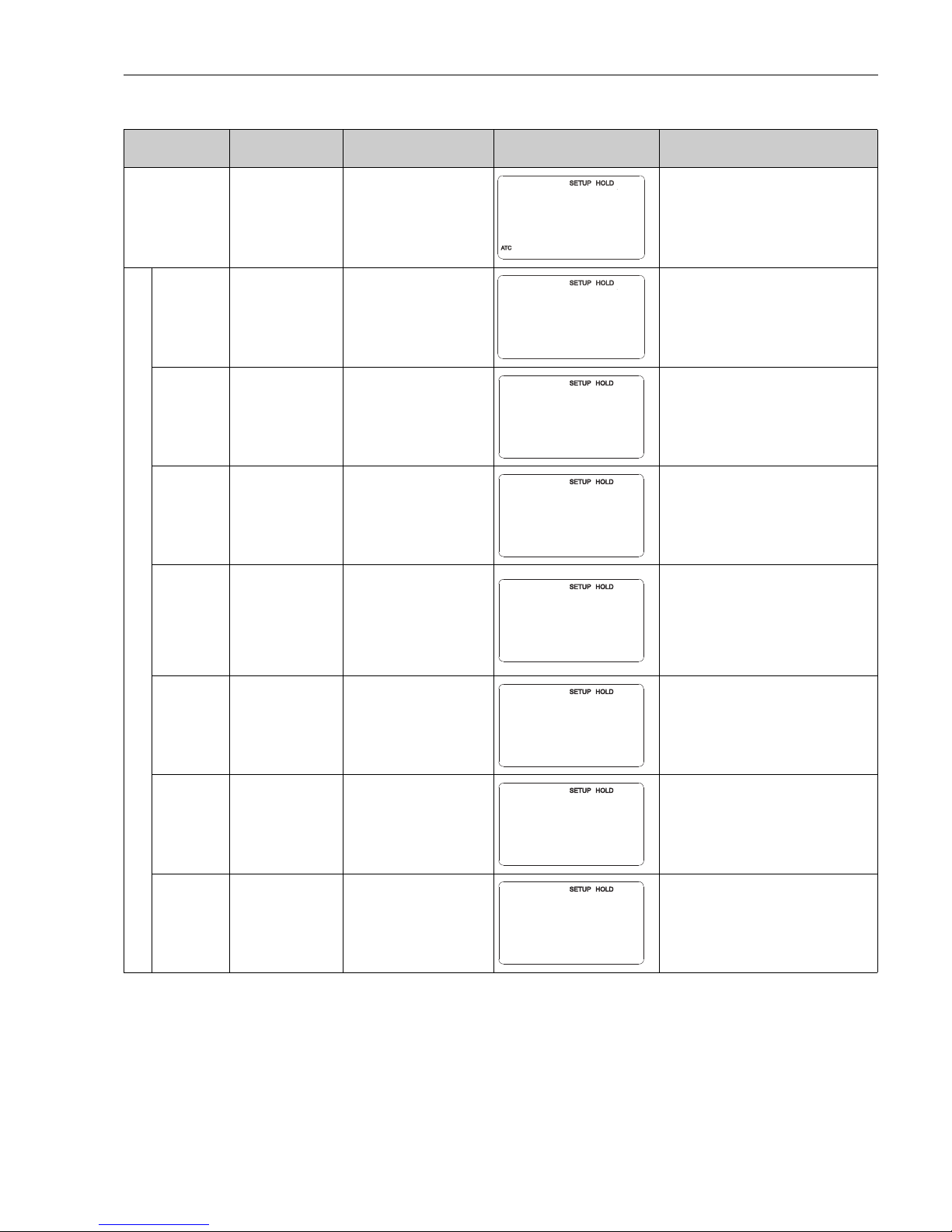
Liquisys M CLM223F Commissioning
Endress+Hauser 39
Coding Field Setting range
(Factory settings, bold)
Display Info
R
RELAY function
group
Relay contact settings.
R1
Select contact to be
configured
Rel1
Rel2
R2
Switch function of
R1 off or on
Off
On
All the settings are retained.
R3
Enter the switch-on
point of the contact
cond/ind: 2000 mS/cm
conc: 99.99 %
Never set the switch-on point and the
switch-off point to the same value!
(Only the operating mode selected in A1
is displayed.)
R4
Enter the switch-off
point of the contact
cond/ind: 2000 mS/cm
conc: 99.99 %
Entering a switch-off point selects either a
Max contact (switch-off point < switch-on
point) or a Min contact (switch-off point >
switch-on point), thereby implementing a
hysteresis that is constantly required (see
"Illustration of the alarm and limit
functions" figure).
R5
Enter pick-up delay
0 s
0to2000s
R6
Enter drop-out delay
0 s
0to2000s
R7
Enter alarm
threshold
cond/ind: 2000 mS/cm
conc: 99.99 %
If the alarm threshold is undershot/
overshot, this triggers an alarm with the
error message and error current at the
transmitter (note alarm delay in field F3).
If defined as a Min contact, the alarm
threshold must be < switch-off point.
R
RELAIS
R1
Sel.Relay
Rel1
R2
Off
Function
2000
mS/cm
R3
On value
2000
mS/cm
R4
Off value
0
s
R5
On delay
0
s
R6
Off delay
2000
mS/cm
R7
A.Thresh
Page 40
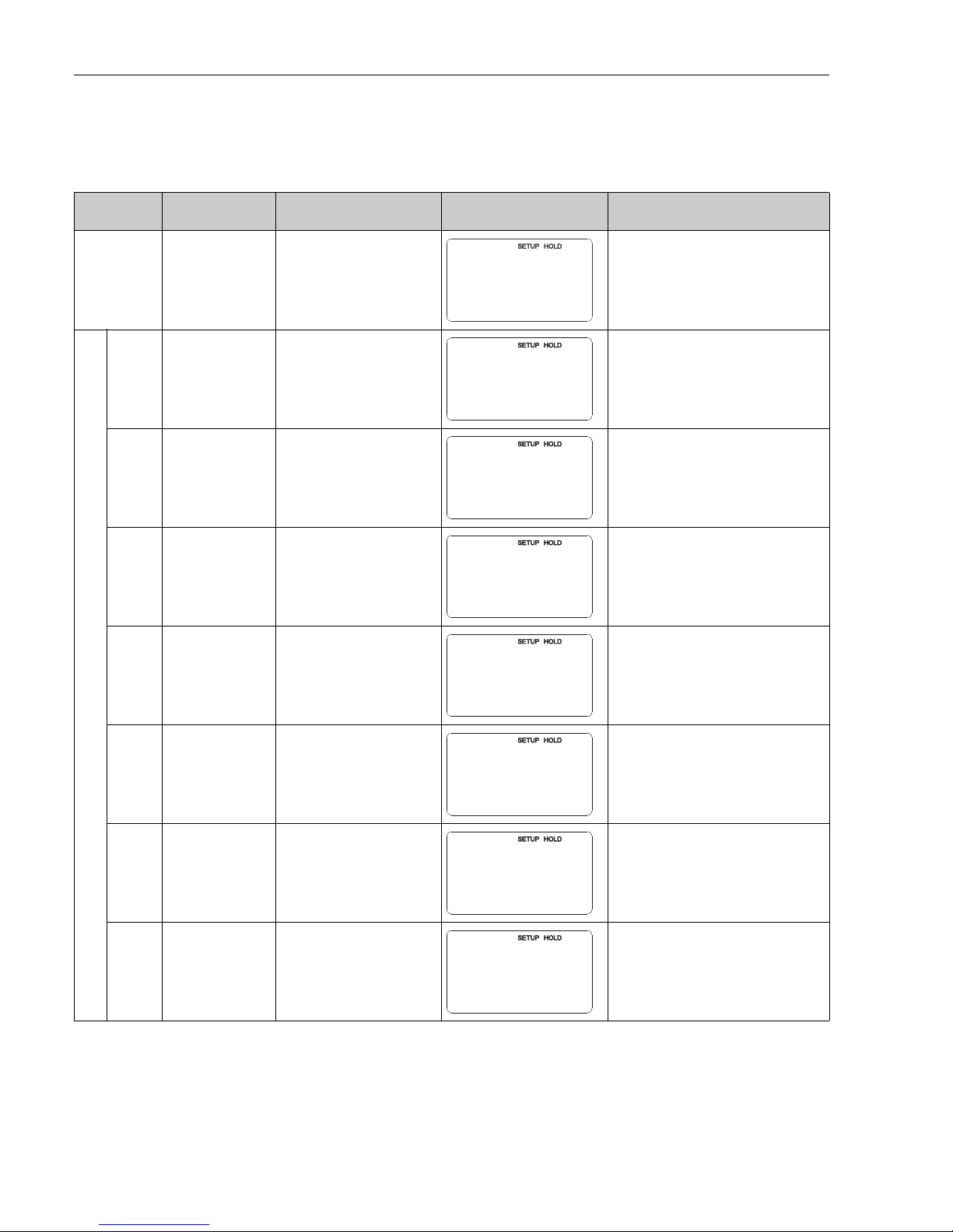
Commissioning Liquisys M CLM223F
40 Endress+Hauser
6.4.7 Temperature compensation with table
This function group is used to perform a temperature compensation with table (field B2).
Enter the T value pairs in the fields T5 and T6.
Coding Field Selection or range
(factory settings bold)
Display Info
T
Function group
ALPHA TABLE
Settings for temperature compensation.
T1 Selection of table
1
1 to 4
Selection of table to be edited.
T2 Select table option
read
edit
T3
Enter number of
table value pairs
1
1 to 10
Up to 10 value pairs can be entered in the
table. These are numbered from 1 to 10
and can be edited individually or in
sequence.
T4
Select table value
pair
1
1 to number of table value pairs
assign
The function chain T4 to T6 will run
through as many times as correspond to
the value in T3. "Assign" appears as the last
step. After confirmation , the system
jumps to T7.
T5
Enter temperature
value (x value)
0.0 °C
-35.0 to 250.0 °C
The temperature values must have a
minimum distance of 1 K.
Factory setting for temperature value of
value pairs in table:
0.0 °C; 10.0 °C; 20.0 °C; 30.0 °C ...
T6
Enter temperature
coefficient (y
value)
2.10 %/K
0.00 to 20.00 %/K
T8
Message, whether or
not the table status
is ok
yes
no
Only display
If status = "no", then set table correctly (all
previous settings are kept) or back to
measurement mode (this makes the table
invalid)
T
ALPHA TAB
T1
1
editCurve
T2
Sel.Table
read
T3
1
No.Elem.
T4
1
Sel.Elem.
T5
0.0
¡C
Temp.val.
T6
2.10
%/K
alpha val
T8
Status ok
yes
Page 41
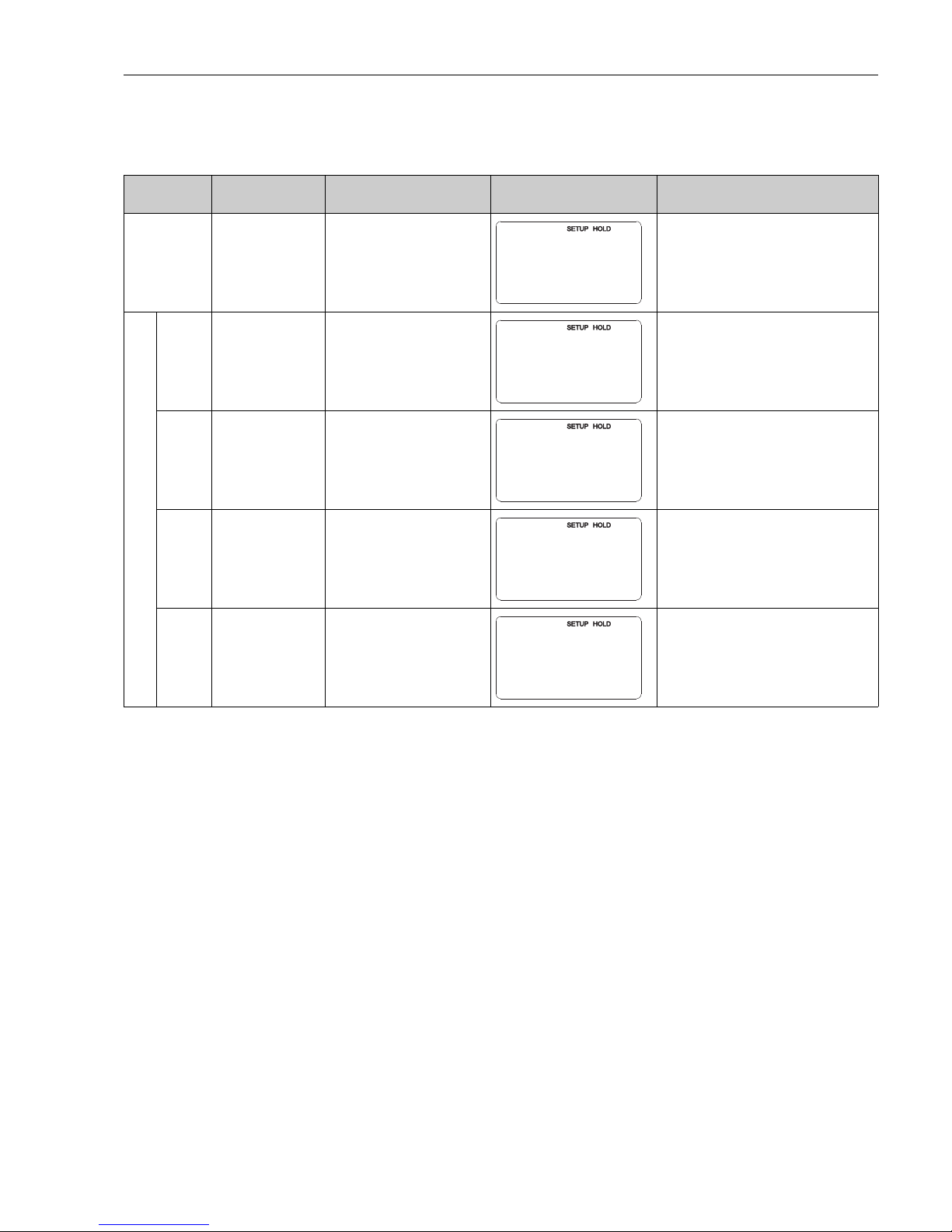
Liquisys M CLM223F Commissioning
Endress+Hauser 41
6.4.8 Determination of the temperature coefficient
This function group is used to determine the temperature coefficient.
Coding Field Selection or range
(factory settings bold)
Display Info
D
Function group
TEMPERATURE
COEFFICIENT
D1
Enter compensated
conductivity
current value
0 to 9999
Edit the measured (uncompensated)
conductivity value you have determined at
25 °C in the medium used in the process.
D2
Display of
uncompensated
conductivity
current value
0 to 9999
The uncompensated conductivity is
displayed (no edit).
D3
Display of current
temperature
current value
-35.0 to +250.0 °C
The current temperature is displayed (no
edit). Please note down this value.
D4
Display of the
value determined
Please note down this value.
D
Det.alpha
2000
D1
µS/cm
Cond.comp
2077
D2
µS/cm
Cond.unc.
60.0
D3
¡C
Meas.temp
2.20
D4
%/K
alpha val
Page 42

Commissioning Liquisys M CLM223F
42 Endress+Hauser
6.4.9 Concentration measurement
The transmitter can convert conductivity values to concentration values. For this, set the
operating mode to Concentration measurement (see field A1).
Then, you must enter the basic data to which the concentration calculation should refer.
You require the conductivity characteristics of the medium. To get the characteristics, you
can either refer to the data sheets of the medium or determine the characteristics yourself.
1. To do so, create samples of the medium with the concentrations occurring in your
process.
2. Measure the uncompensated conductivity of these samples at temperatures which
likewise occur in your process.
– For variable process temperature:
If the variable process temperature should be taken into account for concentration
measurement, you must measure the conductivity of each created sample at two
different temperatures at least (ideally at the lowest and highest process
temperature). The temperature values for the various samples must be identical.
However, the difference between the temperatures must be at least 0.5 °C.
At least two differently concentrated samples measured at two different
temperatures are required because the transmitter needs a minimum of four
references.
– For constant process temperature:
Measure the differently concentrated samples at this constant process temperature.
A minimum of two samples is necessary.
Page 43
Liquisys M CLM223F Commissioning
Endress+Hauser 43
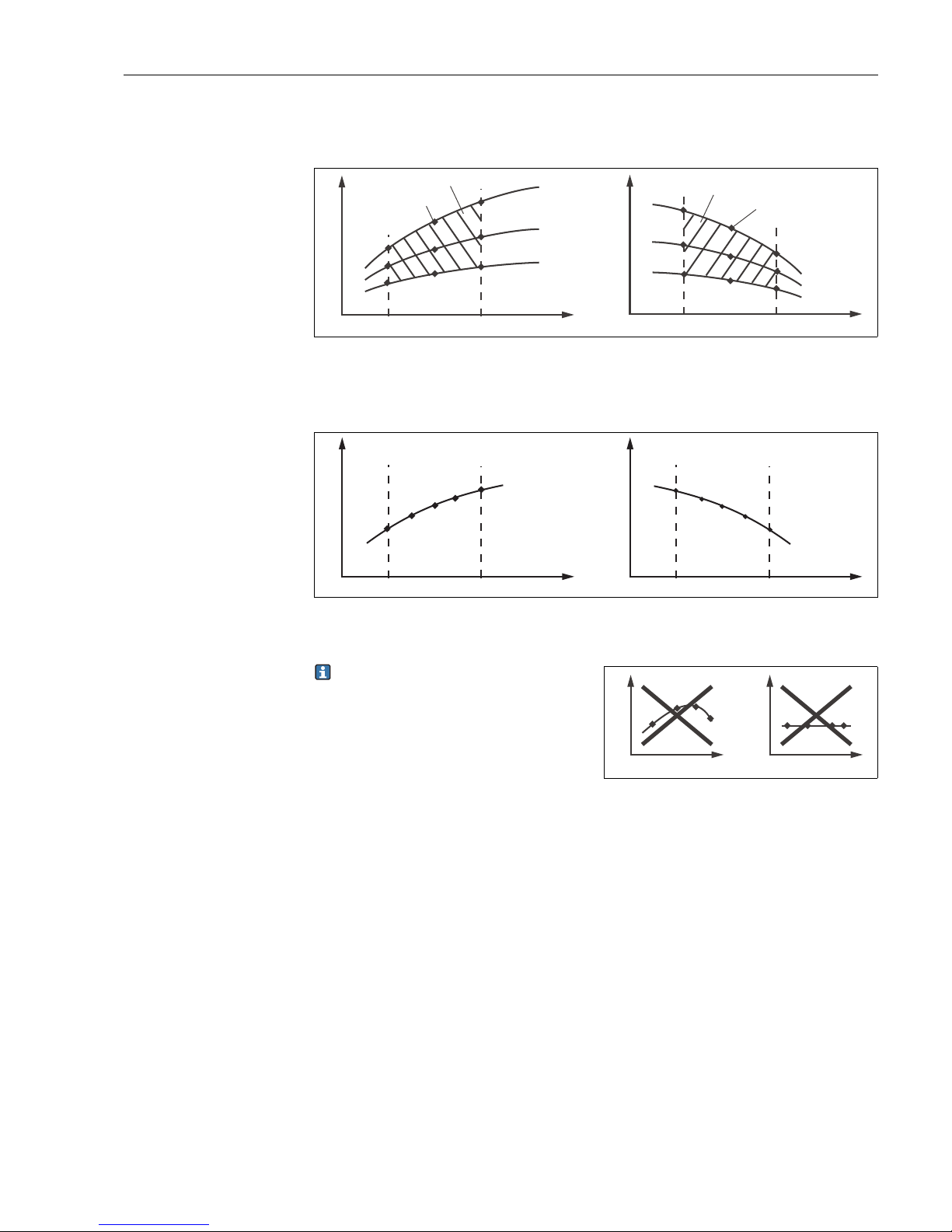
Finally, you should have measuring data which are similar to those shown in the following
figures:
C07-CLD132xx-05-06-00-xx-012.eps
Fig. 23: Measured data for variable process temperatures (example)
C
T
Conductivity
Concentration
Temperature
12Measuring point
Measuring range
C07-CLD132xx-05-06-00-xx-015.epsB
Fig. 24: Measured data for a constant process temperature (example)
C
Conductivity
Concentration
T1Constant temperature
Measuring range
The characteristics received from the
measuring points must be strictly
monotonously increasing or strictly
monotonously decreasing in the range
of the process conditions. Therefore,
neither maxima / minima nor ranges
with a constant behaviour can occur.
Curve profiles such as those in
å 25 are not permitted.
C07-CLD132xx-05-06-00-xx-016.eps
Fig. 25: Impermissible curve profiles
Conductivity
C Concentration
κ
κ
CCC
min
C
min
T
1
T
1
T
2
T
2
T
3
T
3
C
max
C
max
2
2
1
1
k
C
1
T
C
min
C
max
k
C
1
T
C
min
C
max
κ
C
C
κ
Page 44
Commissioning Liquisys M CLM223F
44 Endress+Hauser
Value entry
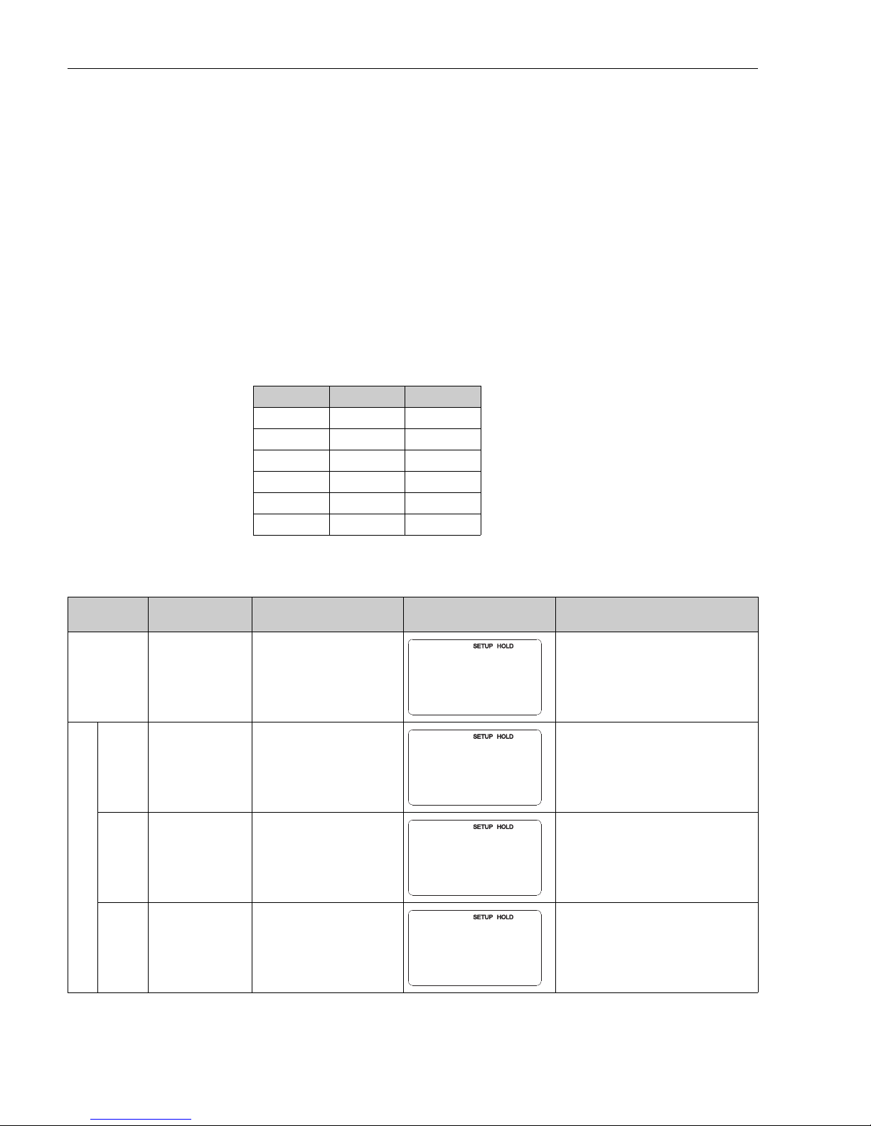
Enter the three characteristic values for each measured sample in the fields K7 to K9 (value
triplets of uncompensated conductivity, temperature and concentration).
• Variable process temperature:
Enter at least four value triplets.
• Constant process temperature:
Enter at least two value triplets.
Pay attention to the following:
• Please make sure that the concentrations and temperatures measured for your samples
correspond to the measuring range of the process. If the measured values of the process
are outside the range of your sample values, this considerably reduces the level of accuracy
and the error message E078 or E079 will be displayed.
• If you enter an additional value triplet of 0 μS/cm and 0 % for each temperature used, you
can work from the start of measuring range with sufficient accuracy and without an error
message.
Enter the values in the order of increasing concentration (see the following example).
Basic version does not include functions in italic.
mS/cm % °C
240 96 60
380 96 90
220 97 60
340 97 90
120 99 60
200 99 90
Coding Field Selection or range
(factory settings bold)
Display Info
K
Function group
CONCENTRATION
Four fixed and four editable concentration
fields are stored in this function group.
K1
Selection of
concentration curve
to be used to
calculate the display
value
NaOH 0 to 15 %
H
2SO4
0 to 30 %
H
3PO4
0 to 15 %
HNO
3
0 to 25 %
User 1 to 4
K2
Selection of
correction factor10.5 to 1.5
If required select a correction factor (only
available for the user table).
K3
Select the table to be
edited
1
1 to 4
When editing a curve, another curve
should be used to calculate the current
display values (see K1).
K
CONCENTRA
K1
NaOH
akt.Curve
K2
1
Conc.Fact
K3
1
editCurve
Page 45
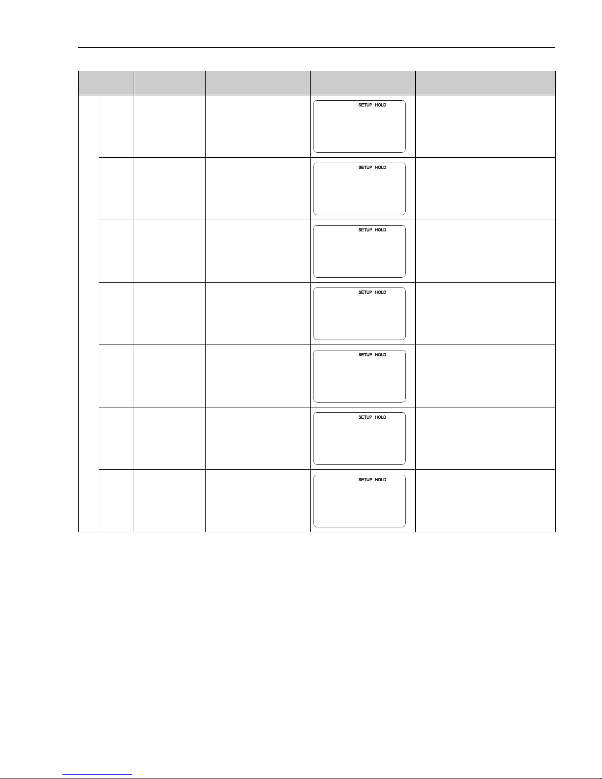
Liquisys M CLM223F Commissioning
Endress+Hauser 45
K4
Select the table
option
read
edit
This selection applies to all concentration
curves.
K5
Enter number of
reference triplets11 to 16
Each triplet consists of three numeric
values.
K6 Select triplet
1
1 to number of triplets in K5
Any triplet can be edited.
K7
Enter
uncompensated
conductivity value
for K6
0.0 to 9999 mS/cm
The function chain K6 to K9 will run
through automatically as many times as
corresponds to the value in K5. Then the
system jumps to K10.
K8
Enter concentration
value for K6
0.00 to 99.99 %
Measuring unit selected as in A2.
Format selected as in A3.
K9
Enter temperature
value for K6
-35.0 to 250.0 °C
K10
Message whether or
not the table status
is ok
yes
no
Only display
If not, then set table correctly (all previous
settings are kept) or back to measurement
mode (this makes the table invalid).
Coding Field Selection or range
(factory settings bold)
Display Info
K4
read
Table
K5
1
No.Elem.
K6
1
Sel.Elem.
K7
0.0
µS/cm
conduct.
K8
0.0
%
concentr.
K9
0.0
¡C
Temp.val.
K10
Status ok
yes
Page 46
Commissioning Liquisys M CLM223F
46 Endress+Hauser
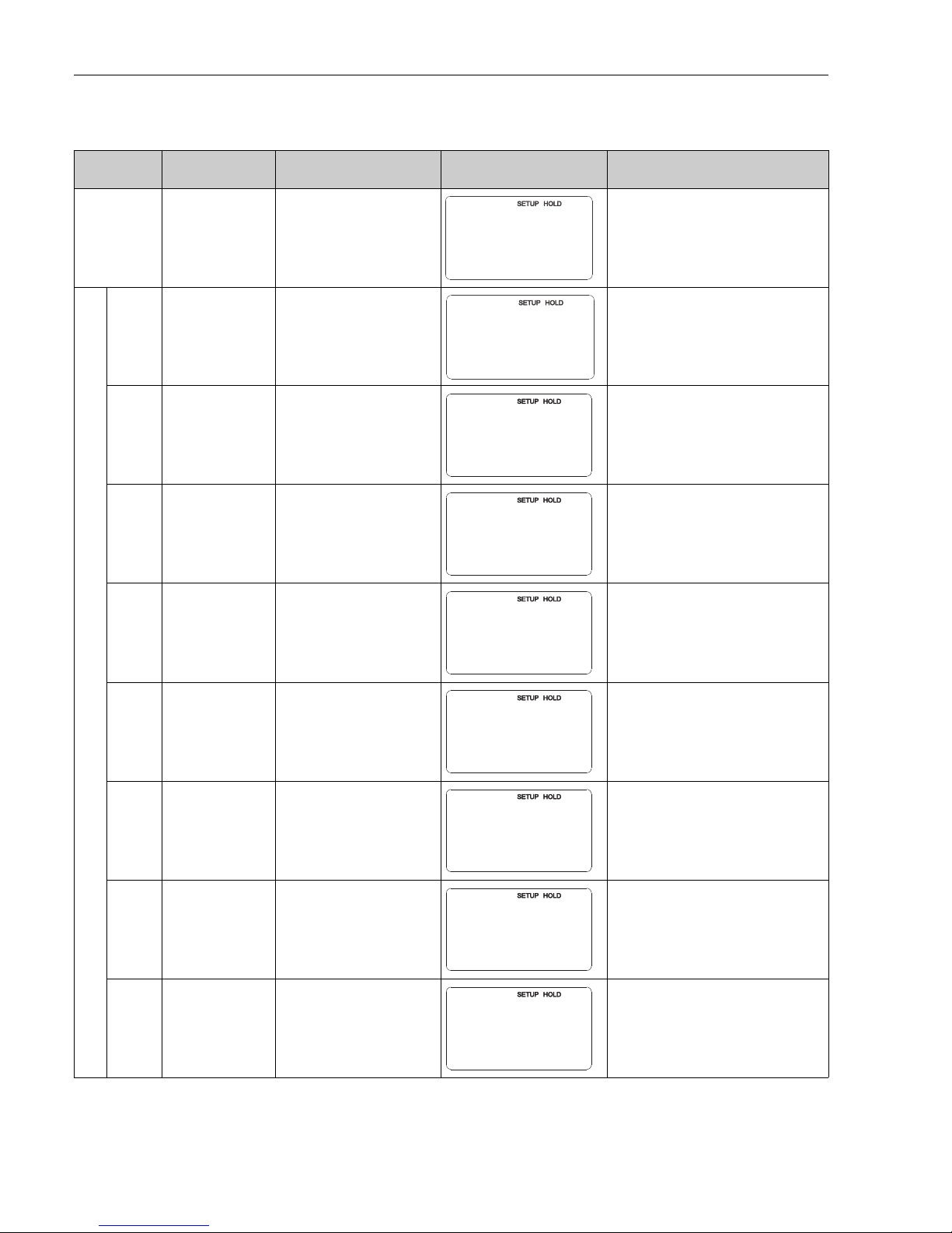
6.4.10 Service
Coding Field Setting range
(Factory settings, bold)
Display Info
S
SERVICE function
group
Service function settings.
S1 Select language
ENG = English
GER = German
FRA = French
ITA = Italian
NL = Dutch
ESP = Spanish
This field has to be configured once during
device configuration. Then you can exit S1
and continue.
S2 HOLD effect
froz = last value
fix = fixed value
"froz" = Display of last value before
activation of hold.
"fix" = When hold is active, the fixed value
entered in S3 is displayed.
S3
Enter fixed value for
current output
0
0 to 100 % (of current output
value)
Only if S2 = fixed value
S4 Configure Hold
S+C = Hold during setup and
calibration
Cal = Hold during calibration
Setup = Hold during setup
None = no hold
S = setup
C = calibration
S5 Manual Hold
Off
On
S6
Enter Hold dwell
period
10 s
0 to 999 s
S7
Enter SW upgrade
release code for Food
package
0000
0000 to 9999
The release code for the "Food" package is
entered in the factory already. You have to
edit this code only after replacement of the
central module.
S8
Order number is
displayed
If the device is upgraded, the order code is
not automatically adjusted.
S
SERVICE
S1
Language
ENG
S2
froz.
Holdeffec
S3
0
Fixed Val
S+C
S4
Auto HOLD
S5
Man. HOLD
Off
10
S6
s
Cont.Time
0000
S7
FoodCode
order
S8
CD0005
Page 47
Liquisys M CLM223F Commissioning
Endress+Hauser 47
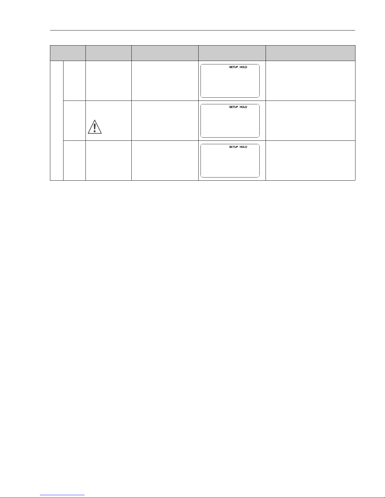
S9
Serial number is
displayed
S10
Reset the device to
the basic settings
no
Sens = sensor data
Facty = factory settings
Sens = Sensor data are deleted (temp.
offset, airset value, cell constant,
installation factor, serial number).
Facty = all data except for the language
(field S1) are deleted and reset to the
factory setting!
S11 Perform device test
No
Displ = display test
Coding Field Setting range
(Factory settings, bold)
Display Info
S9
12345678
SerNo
S10
S.Default
no
S11
Test
no
Page 48
Commissioning Liquisys M CLM223F
48 Endress+Hauser
Compensation of the internal resistance
If you use a conductive sensor in higher conductivities (> 45 mS/cm) you should compensate
the internal resistance of the transmitter. Otherwise a measuring error of more than 1 %
could occur in some cases.
With the fields S12 to S14 the transmitter determines and saves its internal resistance. The
conductivity will be compensated by this value.
Inductive sensors do not require such a compensation.
To perform the compensation proceed as follows:
1. Disconnect the transmitter from power.
2. Remove the transmitter.
3. Disconnect the sensor and connect the test resistor (included in the delivery) at the
terminals 83 and 84. Use the delivered resistor - no other one!
4. Reconnect the power.
5. Perform the menu fields S12 to S14.
To reinstall the transmitter proceed as follows:
1. Disconnect the transmitter from power.
2. Remove the test resistor.
3. Connect the sensor (see chapter "Wiring").
4. Reinstall the transmitter (see chapter "Installation").
5. Reconnect the power.
The cable resistance is not considered (see field A6).
Coding Field Setting range
(Factory settings, bold)
Display Info
S12
Compensation of the
internal resistance
off
on
Start the compensation.
S13
Status of resistance
determination
wait
o. k.
E xxx
Countdown: 30 s
If the status is not o. k. error E xxx will be
displayed.
S14
Store the
compensation?
yes
no
new
If S13 = E xxx, only "yes" or "no".
If "new" = jump back to S12.
The internal resistance will be stored and
will be valid till a new compensation is
performed.
S12
off
Error
Ri-Calib.
S13
Status30s
wait
S14
yes
Store
Page 49
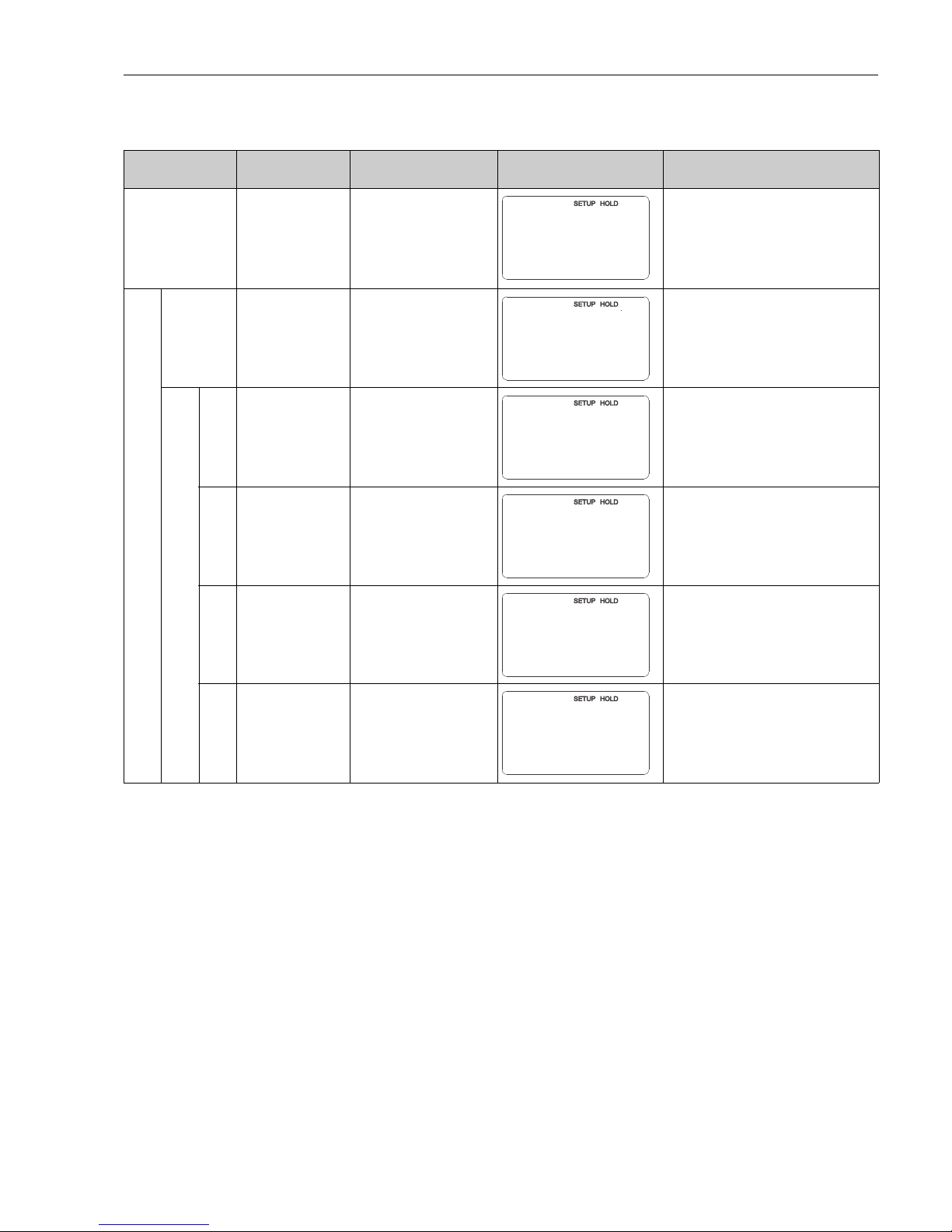
Liquisys M CLM223F Commissioning
Endress+Hauser 49
6.4.11 E+H Service
Coding Field Setting range
(Factory settings, bold)
Display Note
E
E+H SERVICE
function group
Information on the device version
E1 Select module
Contr = controller (1)
Trans = transmitter (2)
Main = power unit (3)
Sens = sensor(4)
E111
E121
E131
E141
Software version is
displayed
If E1 = contr: instrument software
If E1 = trans, main: module firmware
If E1 = sens: sensor software
E112
E122
E132
E142
Hardware version is
displayed
Only display function
E113
E123
E133
E143
Serial number is
displayed
Only display function
E114
E124
E134
E144
Module ID is
displayed
Only display function
E
E+H SERV
E1
Select
Contr
E111
SW-Vers.
xx.xx
E112
HW-Vers.
xx.xx
E113
12345678
SerNo
E114
Modul-ID
LSG
Page 50
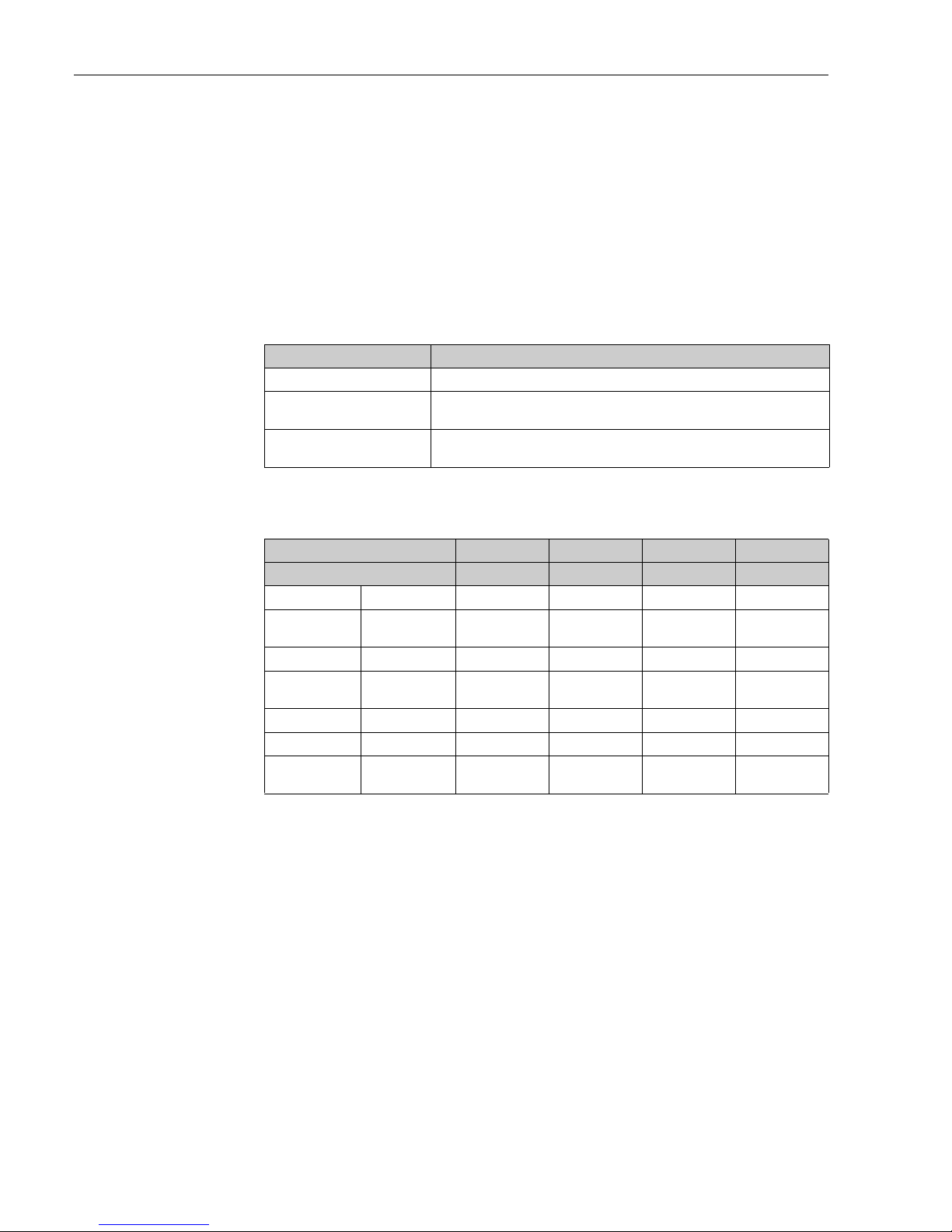
Commissioning Liquisys M CLM223F
50 Endress+Hauser
6.4.12 Remote measuring range switching (MRS)
The remote parameter set switching function permits complete parameter sets to be entered
for up to 4 substances.
Individual settings for each parameter set:
• Operating mode (conductivity or concentration)
• Temperature compensation
• Current output (main parameter and temperature)
• Concentration table
• Limit relay
Assignment of binary inputs
The transmitter has 2 binary inputs. They can be defined in field M1 as follows:
Settings of the 4 parameter sets
Example: CIP cleaning
Assignment of field M1 Assignment of binary inputs
M1 = 0 MRS not active. The binary input 1 can be used for external hold.
M1 = 1
The binary input 2 can be used to switch between 2 measuring ranges
(parameter sets). The binary input 1 can be used for external hold.
M1 = 2
The binary inputs 1 and 2 can be used to switch between 4 measuring ranges
(parameter sets). This is the setting used in the following example.
Binary input 1 0 0 1 1
Binary input 2 0 1 0 1
Parameter set1234
Coding /
software field
Medium Beer Water
Alkaline
solution
Acid
M4 Operating mode Conductivity Conductivity Concentration Concentration
M8, M9 Current output 1 to 3 mS/cm 0.1 to 0.8 mS/cm0.5 to 5% 0.5 to 1.5 %
M6 Temp. comp. User Tab. 1 linear - -
M5Conc. tab.--NaOHUser Tab.
M10, M11 Limits on: 2.3 mS/cm
off: 2.5 mS/cm
on: 0.7 μS/cm
off: 0.8 μS/cm
on: 2 %
off: 2.1 %
on: 1.3 %
off: 1.4 %
Page 51
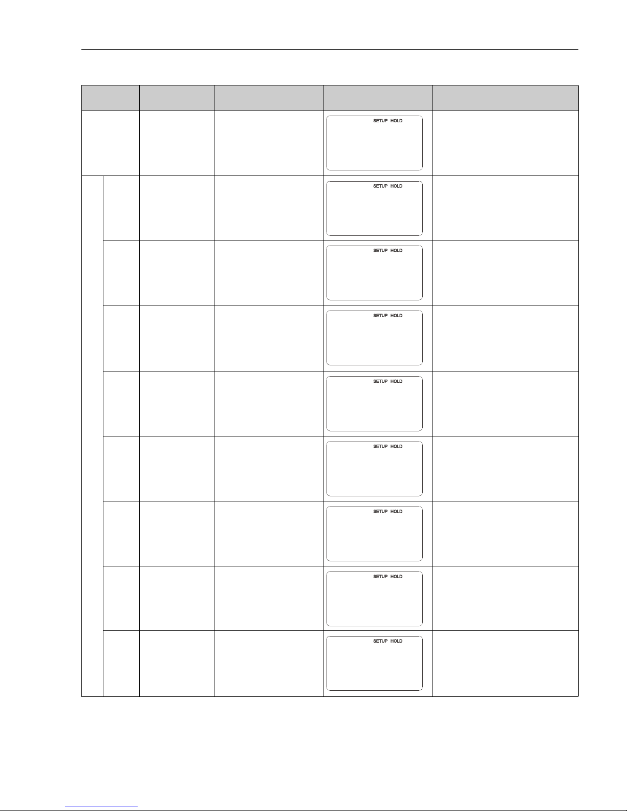
Liquisys M CLM223F Commissioning
Endress+Hauser 51
Coding Field Selection or range
(factory settings bold)
Display Info
M
Function group
MRS
Settings of remote parameter set switching
(measuring range switching).
M1 + M2: apply to measuring mode.
M3 to M11: apply to configuration of
parameter sets.
M1 Select binary inputs
1
0, 1, 2
0 = no MRS
1 = 2 parameter sets selectable via binary
input 2. Binary input 1 for hold.
2 = 4 parameter sets selectable via binary
inputs 1+2.
M2
Displays active
parameter set or, if
M1=0, select active
parameter set
1
1 to 4 if M1 = 0
If M1 = 0, selectable.
If M1 = 1 or 2, disp lay depending on b inar y
inputs.
M3
Select parameter set
to be configured in
M4 to M16
1
1 to 4 if M1=0
1 to 2 if M1=1
1 to 4 if M1=2
Selection of parameter set to be
configured (the active parameter set is
selected in M2 or with the binary inputs).
M4
Select operating
mode
cond = conductivity
conc = concentration
The operating mode can be individually
defined for each parameter set.
M5 Select medium
NaOH, H2SO4, H3PO4, HNO3
Tab 1 to 4
Only available if M4 = conc.
M6
Select temperature
compensation
none, lin, NaCl,
Tab 1 to 4 if M4 = cond
Only available if M4 = cond.
M7 Enter value
2.10 %/K
0 to 20 %/K
Can only be entered if M6 = lin.
M8
Enter measured
value for 0/4 mA
value
Cond.: 0 to 2000 mS/cm
Conc.: 0 to 99.99 %
For concentration:
edit Unit in field A2
edit Format in field A3
M
MRS
M1
Bin.Input
2
M2
Act.MR
1
M3
Edit MR
1
M4
Oper.Mode
cond.
M5
Conc.Tab.
NaOH
M6
TempComp
lin
M7
%/K
alpha val
2.10
M8
µS/cm
0/4mA
0
Page 52
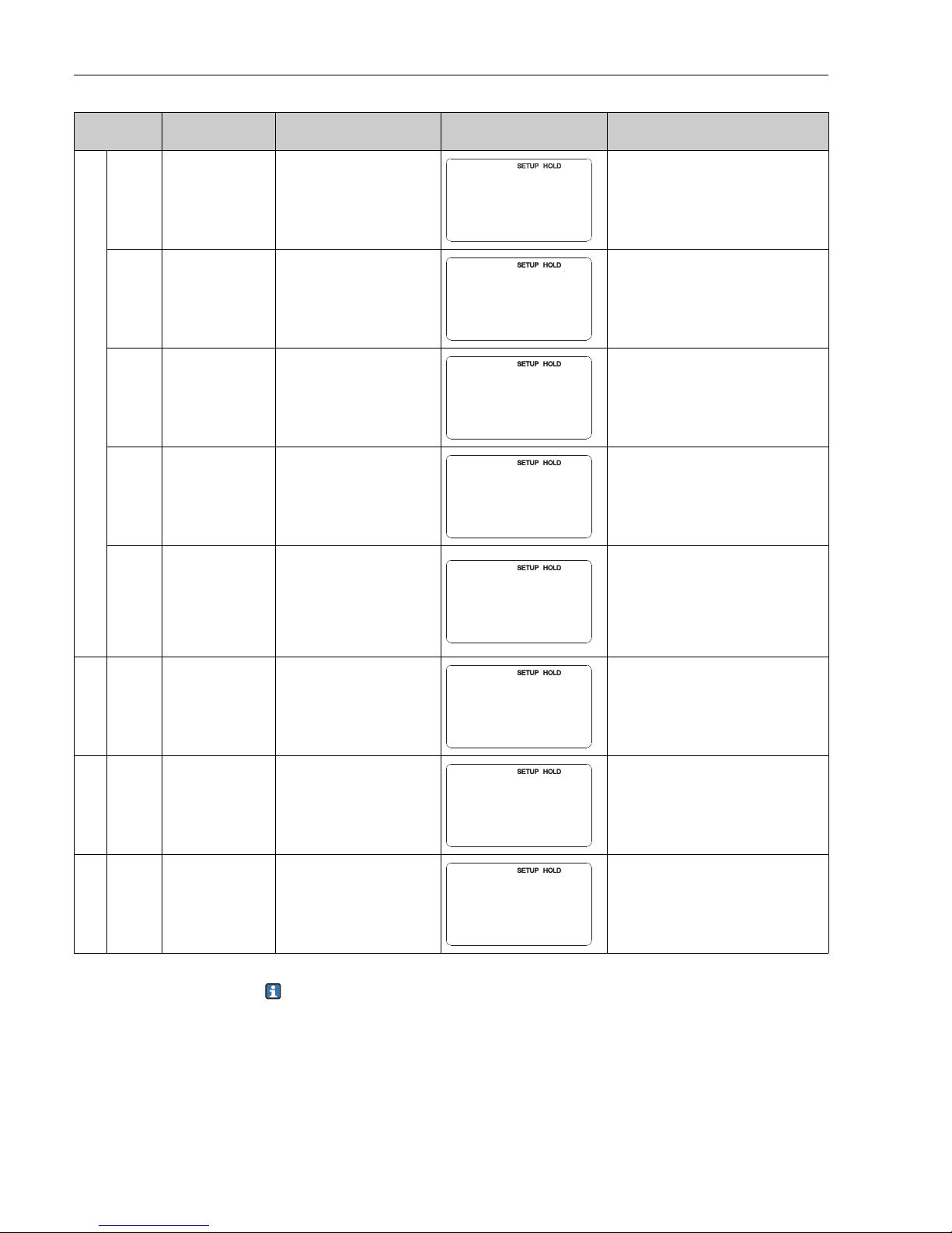
Commissioning Liquisys M CLM223F
52 Endress+Hauser
If remote parameter set switching is selected, the parameter sets that have been
entered are processed internally but the fields A1, B1, B3, R2, K1, O212, O213 show
the values of the first measuring range.
M9
Enter measured
value for 20 mA
value
Cond.: 0 to 2000 mS/cm
Conc.: 0 to 99.99 %
For concentration:
edit Unit in field A2
edit Format in field A3
M10
Select contact to be
configured
Rel 1
Rel 2
M11
Switch function of
relais off or on
Off
On
All settings are retained.
M12
Enter switch-on
point for limit
Cond.: 0 to 2000 mS/cm
Conc.: 0 to 99.99 %
For concentration:
edit Unit in field A2
edit Format in field A3
Never set the switch-on point and the
switch-off point to the same value!
M13
Enter switch-off
point for limit
Cond.: 0 to 2000 mS/cm
Conc.: 0 to 99.99 %
The switch-off point entry selects a max
contact (switch-off point < switch-on
point) or a min contact (switch-off point >
switch-on point), thereby implementing an
always required hysteresis function. Never
set the switch-off point and the switch-on
point to the same value.
M14 Enter pick-up delay
0 s
0 to 2000 s
M15 Enter drop-out delay
0 s
0 to 2000 s
M16
Enter alarm
threshold
Cond.: 0 to 2000 mS/cm
Conc.: 0 to 99.99 %
Coding Field Selection or range
(factory settings bold)
Display Info
M9
mS/cm
20 mA
2000
Rel1
M10
Sel.Relay
M11
Off
Function
2000
M12
mS/cm
PV on
2000
M13
mS/cm
PV off
0
s
M14
On Delay
0
s
M15
Off Delay
0
mS/cm
M16
A.Tresh
Page 53
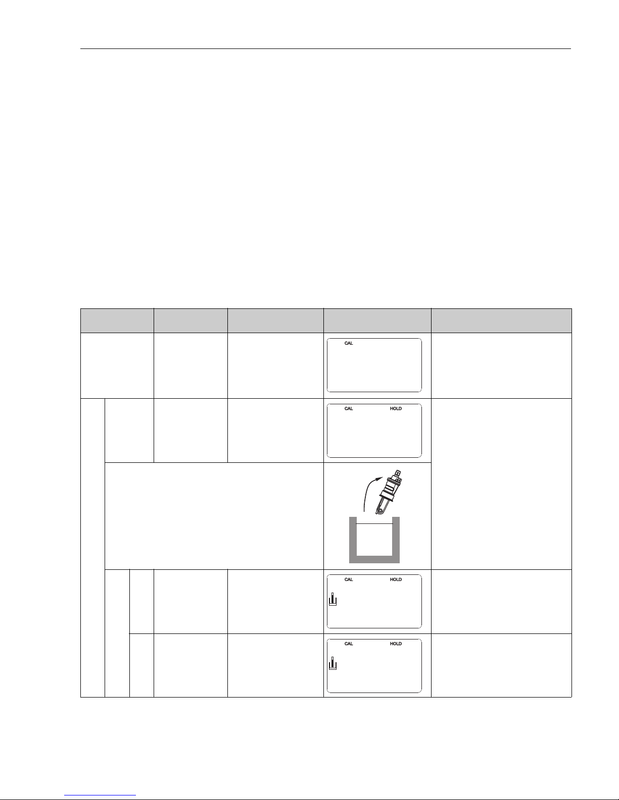
Liquisys M CLM223F Commissioning
Endress+Hauser 53
6.5 Calibration
To access the "Calibration" function group, press the CAL key.
This function group is used to calibrate and adjust the transmitter. Two different types of
calibration are possible:
• Calibration by measurement in a calibration solution of a known conductivity.
• Calibration by entering the exact cell constant of the conductivity sensor.
Pay attention to the following:
• At first start-up of inductive sensors, an airset is absolutely required in order for the
measuring system to be able to generate accurate measuring values.
• If the calibration procedure is aborted by pressing the PLUS and MINUS keys at the same
time (return to C114, C126 or C136) or if the calibration is faulty, then the previous
calibration data are reinstated. A calibration error is indicated by the “ERR” message and
flashing of the sensor symbol on the display.
Repeat calibration!
• The instrument is automatically switched to hold during calibration (factory setting).
• After calibration, the system jumps back to the measuring mode. During the hold dwell
period the hold symbol is displayed.
• For conductive sensors only the fields C121 to C126 are relevant.
Coding Field Selection or range
(factory settings bold)
Display Info
C
Function group
CALIBRATION
Calibration settings.
C1 (1)
Calibration of
inductive sensors
with a ring-shaped
opening
Airs = Airset (1)
Cellc = cell constant (2)
InstF = installation
factor (3)
When commissioning inductive sensors,
an airset is mandatory.
The calibration of the sensor is to be
performed in air. The sensor must be dry.
Remove sensor from the medium and dry completely.
C111
Residual coupling
start calibration
(airset)
current measured value Start calibration with CAL.
C112
Residual coupling is
displayed (airset)
-80.0 to 80.0 μS/cm
Residual coupling of measuring system
(sensor and transmitter).
C
CALIBRAT
C1
Calibrat
AirS
~
~
~
~
~
~
~
~
C111
µS/cm
AirSet
0.0
C112
µS/cm
AirSetVal
5.3
Page 54
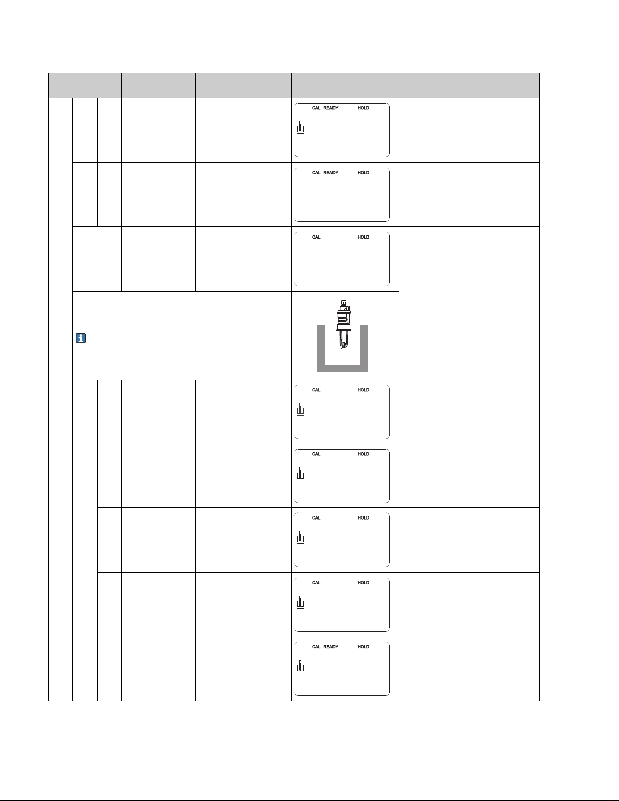
Commissioning Liquisys M CLM223F
54 Endress+Hauser
C113
Calibration status is
displayed
o.k.
E xxx
If the calibration status is not o.k., the
second display line shows an explanation
of the error.
C114
Store calibration
results?
yes
no
new
If C113 = E xxx, then only no or new.
If new, return to C.
If yes/no, return to “Measurement”.
C1 (2)
Calibration of cell
constant
Airs = Airset (1)
Cellc = cell constant (2)
InstF = installation
factor (3)
The sensor should be immersed at a
sufficient distance from the vessel wall
(installation factor has no influence if
a > 15 mm / 0.59").
Immerse sensor in calibration solution.
This describes the calibration for temperature compensated
conductivity. For calibration with uncompensated
conductivity set the temperature coefficient to 0.
C121
Enter calibration
temperature (MTC)
25 °C
-35.0 to 250.0 °C
Only exists if B1 = fixed.
C122
Enter value of
calibration solution
2.10 %/K
0.00 to 20.00 %/K
This value is specified in the Technical
Information of all E+H calibration
solutions. You can also use the printed-on
table to calculate the value.
Set to 0 for calibration with
uncompensated values.
C123
Enter correct
conductivity value of
calibration solution
(25 °C)
current measured value
0.0 μS/cm to 9999 mS/cm
You should select a value close to the
application range.
C124
Calculated cell
constant is displayed
0.1 to 5.9 to 99.99 cm
-1
The calculated cell constant is displayed
and entered in A5.
C125
Calibration status is
displayed
o.k.
E xxx
If the calibration status is not o.k., the
second display line shows an explanation
of the error.
Coding Field Selection or range
(factory settings bold)
Display Info
C113
Status
o.k.
C114
Store
yes
C1
Calibrat
Cellc
~
~
~
~
~
~
~
~
C121
°C
ProcTemp.
25.0
%/K
C122
alpha val
2.10
C123
mS/cm
Real. val
10.30
C124
1/cm
Cellconst
1.000
C125
Status
o.k.
Page 55
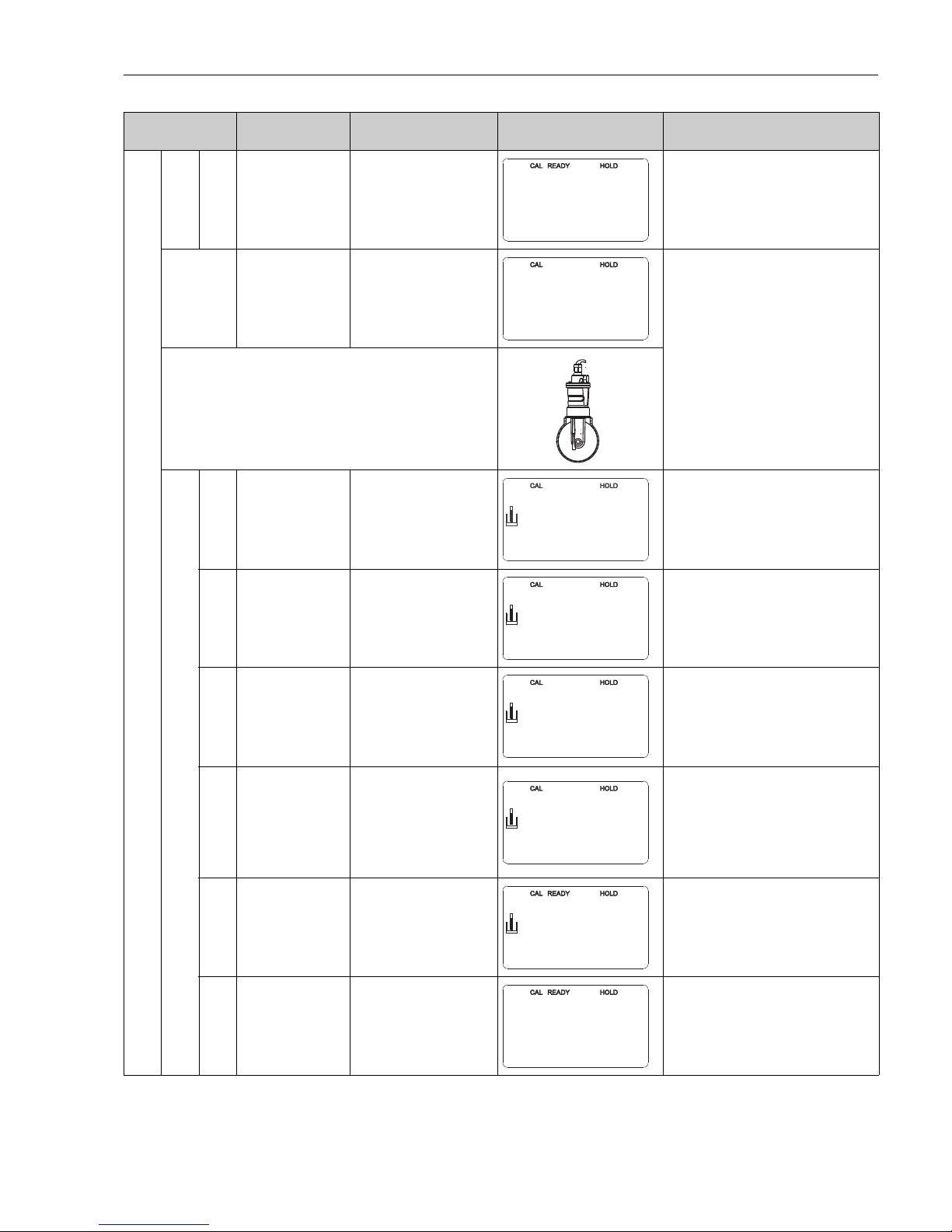
Liquisys M CLM223F Commissioning
Endress+Hauser 55
C126
Store calibration
results?
yes
no
new
If C125 = E xxx, then only no or new.
If new, return to C.
If yes/no, return to “Measurement”.
C1 (3)
Calibration with
sensor adaptation
for inductive sensors
(Plus Package only)
Airs = Airset (1)
Cellc = cell constant (2)
InstF = installation
factor (3)
Sensor calibration with compensation of
wall influence.
On inductive sensors, the distance from
the sensor to the wall of the pipe and the
material of the pipe (conductive or
nonconductive) influence the measured
value. The installation factor shows this
influence. See the technical information
of the installed sensor.
The sensor is installed in the process.
C131
Enter process
temperature (MTC)
25 °C
-35.0 to 250.0 °C
Only exists if B1 = fixed.
C132
Enter value of the
calibration solution
2.10 %/K
0.00 to 20.00 %/K
This value is specified in the TI of all E+H
calibration solutions. You can also use the
printed-on table to calculate the value.
Set to 0 for calibration with
uncompensated values.
C133
Enter correct
conductivity value of
the calibration
solution
current measured value
0.0 μS/cm to 9999 mS/cm
You should select a value close to the
application range.
C134
Calculated
installation factor is
displayed
1
0.10 to 5.00
On inductive sensors, the distance from
the sensor to the wall of the pipe and the
material of the pipe (conductive or
nonconductive) influence the measured
value. The installation factor shows this
influence. See the technical information
of the installed sensor.
C135
Calibration status is
displayed
o.k.
E xxx
If the calibration status is not o.k., the
second display line shows an explanation
of the error.
C136
Store calibration
results?
yes
no
new
If C135 = E xxx, then only no or new.
If new, return to C.
If yes/no, return to “Measurement”.
Coding Field Selection or range
(factory settings bold)
Display Info
C126
Store
yes
C1
Calibrat
InstF
C131
°C
MTC temp.
25.0
C132
%/K
alpha val
2.10
C133
mS/cm
Real val.
10.30
C134
InstFact
1
C135
Status
o.k.
C136
Store
yes
Page 56
Diagnostics and troubleshooting Liquisys M CLM223F
56 Endress+Hauser
7 Diagnostics and troubleshooting
7.1 Troubleshooting instructions
The transmitter constantly monitors its functions itself. If an error occurs which the device
recognizes, this is indicated on the display. The error number is shown below the display of
the main measured value. If more than one error occurs, you can call these up with the
MINUS key.
Refer to the "System error messages" table for the possible error numbers and remedial
measures.
Should a malfunction occur without any transmitter error message, please refer to the
"Process-specific errors" or the "Device-specific errors" tables to localize and rectify the error.
These tables provide you with additional information on any spare parts required.
7.2 System error messages
The system error messages can be called up and selected with the MINUS key.
Error
no.
Display Tests and/or remedial measures Alarm contact Error current
Factory User Factory User
E001 EEPROM memory error 1. Switch device off and then on again.
2. Load device software compatible with the hardware
(with optoscope, see "Optoscope service tool"
section).
3. Load measurement-parameter specific device
software.
4. If the error persists, send in the device for repair to
your local service organisation or replace the device.
Yes No
E002
Instrument not calibrated, calibration
data invalid, no user data, user data
invalid (EEPROM error), instrument
software not suitable to hardware
(controller)
Yes No
E003 Download error
Invalid configuration. Repeat download, check
optoscope.
Yes No
E004
Instrument software version not
compatible with module hardware version
Load software compatible with hardware.
Load measurement-parameter specific device software.
Yes No
E007
Transmitter malfunction, instrument
software not compatible with transmitter
version
Yes No
E008 Sensor or sensor connection faulty Check sensor and sensor connection (Service). Yes Yes
E010
Temperature sensor defective, not
connected or short-circuited
Check temperature sensor and connections; check device
and measuring cable with temperature simulator if
necessary.
Yes No
E025 Limit for Airset offset exceeded
Repeat Airset (in air) or replace sensor. Dry sensor.
Check sensor connection.
No No
E036 Calibration range of sensor exceeded
Clean sensor and recalibrate; if necessary, check sensor
and connections.
No No
E037 Below calibration range of sensor No No
E040 Range of test resistor exceeded Check test resistor No No
E045 Calibration aborted Recalibrate No No
E049
Calibration range of installation factor
exceeded
Check pipe diameter, clean sensor and recalibrate.
No No
E050
Below calibration range of installation
factor
No No
E055 Below main parameter measuring range Immerse sensor in conductive medium or perform Airset Yes No
Page 57
Liquisys M CLM223F Diagnostics and troubleshooting
Endress+Hauser 57
E057
Main parameter measuring range
exceeded
Check measurement and connections; check device and
measuring cable with simulation if necessary.
Yes No
E059 Below temperature measuring range Yes No
E061 Temperature measuring range exceeded Yes No
E063 Below current output range 1
Check measured value and current assignment.
Yes No
E064 Current output range 1 exceeded Yes No
E065 Below current output range 2 Yes No
E066 Current output range 2 exceeded Yes No
E067
Alarm threshold for limit contactor
exceeded
Check measured value, limit setting, alarm threshold
and metering devices.
Yes No
E071 Polarisation Clean sensor; use higher cell constant. Yes No
E077 Temperature outside value table range
Check measurement and tables.
Yes No
E078 Temperature outside concentration table Yes No
E079 Conductivity outside concentration table Yes No
E080 Current output 1 range too small
Increase range in "Current outputs" menu.
Yes No
E081 Current output 2 range too small Yes No
E085 Incorrect setting for error current
If the current range "0 ... 20 mA" was selected in field
O211, the error current "2.4 mA" may not be set.
Yes No
E100 Current simulation active No No
E101 Service function active
Switch off service function or switch device off and then
on again.
No No
E102 Manual mode active No No
E106 Download active Wait for download to finish. No No
E116 Download error Repeat download. Yes No
E150
Distance between temp. values in value
table too small or not monotonously
increasing
Enter correct values in value table (minimum distance
between temperature values of 1 K required)
No No
E152 Live check alarm Check sensor and connection. Yes No
Error
no.
Display Tests and/or remedial measures Alarm contact Error current
Factory User Factory User
Page 58
Diagnostics and troubleshooting Liquisys M CLM223F
58 Endress+Hauser
7.3 Process specific errors
Use the following table to locate and correct errors.
Error Possible cause Tests and / or remedial measures Equipment, spare parts, personnel
Display deviates from
reference measurement
Calibration faulty Calibrate instrument according to
chapter "Calibration".
Calibration solution or sensor certificate
Sensor soiled Clean sensor. See chapter "Cleaning conductivity
sensors".
Incorrect temperature measurement Check temperature value on instrument
and reference unit.
Temperature measuring instrument,
precision thermometer
Incorrect temperature compensation Check compensation method (none /
ATC / MTC) and compensation type
(linear/substance/user table).
Please note: transmitter has separate
calibration and operating temperature
coefficients.
Reference instrument calibration
faulty
Calibrate reference instrument or use
calibrated instrument.
Calibration solution, operating
instructions of reference instrument
Incorrect ATC setting on reference
instrument
Compensation method and
compensation type must be identical on
both instruments.
Operating instructions of reference
instrument
Polarisation error Use suitable sensor:
• Use larger cell constant.
• Use graphite instead of stainless steel
(check resistance).
Measuring range tables e.g. in FA
"Conductivity" or technical data of
conductivity sensors
Incorrect line resistance in field A6 Enter correct value CYK71: 165 /km
Implausible measured
values in general:
– continuous measured
value overflow
– measured value always
000
– measured value too low
– measured value too
high
– measured value frozen
– incorrect current
output value
Short circuit / moisture in sensor Check sensor. See chapter "Checking inductive
conductivity sensors".
Short circuit in cable or junction box Check cable and junction box. See chapter "Checking extension cable
and junction box".
Interruption in sensor Check sensor. See chapter "Checking inductive
conductivity sensors".
Interruption in cable or junction box Check cable and junction box. See chapter "Checking extension cable
and junction box".
Incorrect cell constant setting Check cell constant. Sensor nameplate or certificate
Incorrect output assignment Check assignment of measured values to
current signals.
Incorrect output function Check 0-20 / 4 -20 mA selection and
curve shape (linear /table).
Air cushion in assembly Check assembly and installation.
Grounding short on or in device Measure in insulated container Plastic container, calibration solutions
Transmitter module defective Test with new module. See chapter "Spare parts".
Impermissible instrument operating
state (no response to key actuation)
Switch instrument off and back on. EMC problem: check grounding and line
routing if problem persists or call E+H
Service to test.
Incorrect temperature
value
Incorrect sensor connection Verify connections using connection
diagram; three-wire connection
mandatory.
Connection diagram in chapter "Electrical
connection"
Measuring cable defective Check cable for interruption/short
circuit/ shunt.
Ohmmeter
Incorrect temperature sensor type Select temperature sensor type on
instrument (field B1).
Page 59

Liquisys M CLM223F Diagnostics and troubleshooting
Endress+Hauser 59
Measured value
fluctuates
Measuring cable interferences Connect cable screen according to
connection diagram.
See chapter "Electrical connection".
Signal output line interferences Check line routing, try separate line
routing.
Separate routing of signal output and
measuring input lines
Interference currents in medium Eliminate source of interference or
ground medium close to sensor.
With conductive sensors:
Electromagnetic interferences on
signal lines
Use shielded cables and ground the cable
shield
Incorrect conductivity
measured value in process
No / incorrect temperature
compensation
ATC: select compensation type; linear:
set correct coefficient.
MTC: set process temperature.
Incorrect temperature measurement Check temperature value. Reference instrument, thermometer
Bubbles in medium Suppress bubble formation:
– gas bubble trap
– counterpressure (cover)
– bypass measurement
Polarisation effects (only with
conductive sensors)
Use suitable sensor
• Use larger cell constant
• Use graphite instead of stainless steel
(check resistance)
Measuring range tables e.g. in FA
"Conductivity" or technical data of
conductivity sensors
Flow rate too high (may cause
bubbles)
Reduce flow or choose low turbulence
mounting position.
Interference current in medium (only
when conductive)
Ground medium close to sensor. Most frequent cause of currents in
medium: defective submerged motors
Sensor soiled or coated Clean sensor (see chapter "Cleaning
conductivity sensors").
Heavily soiled media: use spray cleaning.
Incorrect line resistance in field A6 Enter correct value. CYK71: 165 /km
Controller/limit contact
does not work
Controller switched off Activate controller. See fields R2.
Controller in "Manual/Off" mode Choose "Auto" or "Manual/On" mode. Keyboard, REL-key
Pickup delay setting too long Disable or shorten pickup delay. See fields R5.
"Hold" function active “Automatic Hold” during calibration,
“Hold” input activated;
“Hold” via keyboard active.
See fields S2 to S5.
Controller/limit contact
works continuously
Controller in "Manual/On" mode Set controller to "Manual/Off" or "Auto". Keyboard, REL and AUTO keys
Dropout delay setting too long Shorten dropout delay. See field R6.
Control loop interruption Check measured value, current output,
actuators, chemical supply.
No conductivity current
output signal
Line open or short-circuited Disconnect line and measure directly on
instrument.
mA meter 0–20 mA
Output defective See chapter "Instrument specific errors".
Fixed conductivity current
output signal
Current simulation active Switch off simulation. See field O2 (2).
Impermissible operating state of
processor system
Switch instrument off and back on. EMC problem: check installation, screen,
grounding if problem persists / call E+H
Service to test.
Incorrect current output
signal
Incorrect current assignment Check current assignment: 0–20 mA or
4–20 mA?
Field O211
Total load in current loop excessive
(> 500 .)
Disconnect output and measure directly
on instrument.
mA meter for 0–20 mA DC
EMC (interference coupling) Disconnect both output lines and
measure directly on instrument.
Use shielded lines, ground screens on
both sides, route line in other duct if
necessary.
Error Possible cause Tests and / or remedial measures Equipment, spare parts, personnel
Page 60

Diagnostics and troubleshooting Liquisys M CLM223F
60 Endress+Hauser
Current output table not
accepted
Value interval too small Select practical intervals
No temperature output
signal
Instrument does not have 2nd
current output
Refer to nameplate for variant; change
LSCH-x1 module if necessary.
Module LSCH-x2,
see chapter "Spare parts".
HOLD active Check HOLD configuration
Error Possible cause Tests and / or remedial measures Equipment, spare parts, personnel
Page 61
Liquisys M CLM223F Diagnostics and troubleshooting
Endress+Hauser 61
7.4 Instrument specific errors
The following table helps you during the diagnosis and points to any spare parts required.
Depending on the degree of difficulty and the measuring equipment present, diagnosis is
carried out by:
• Trained operator personnel
• The user's trained electrical technicians
• Company responsible for system installation/operation
• Endress+Hauser Service
Information on the exact spare part designations and on how to install these parts can be
found in the "Spare parts" section.
Error Possible cause Tests and/or remedial measures Execution, tools, spare parts
Device cannot be
operated, display value
9999
Operation locked
Press CAL and MINUS keys
simultaneously.
See "Function of keys" section.
Display dark, no lightemitting diode active
No line voltage Check whether line voltage is present. Electrical technician/e.g. multimeter
Supply voltage wrong/too low
Compare actual line voltage and
nameplate data.
User
(data for energy supply company or
multimeter)
Connection faulty
Terminal not tightened;
insulation jammed;
wrong terminals used.
Electrical technician
Device fuse defective
Compare line voltage and the nameplate
data and replace fuse.
Electrical technician/suitable fuse;
see drawing in "Spare parts" section.
Power unit defective Replace power unit, note variant.
On-site diagnosis by Endress+Hauser
Service, test module necessary
Central module defective Replace central module, note variant.
On-site diagnosis by Endress+Hauser
Service, test module necessary
Display dark, lightemitting diode active
Central module defective
(module: LSCH/LSCP)
Renew central module, note variant.
On-site diagnosis by Endress+Hauser
Service, test module necessary
Display is on but
– No change in display
and/or
– Device cannot be
operated
Device or module in device not
correctly mounted
Reinstall module
Perform with the aid of the installation
drawings in the "Spare parts" section.
Operating system in unpermitted
mode
Switch device off and then on again.
Poss. EMC problem: if this persists, check
the installation or have it checked by
Endress+Hauser Service.
Device gets hot
Voltage wrong/too high
Compare line voltage and nameplate
data.
User, electrical technician
Power unit defective Replace power unit.
Diagnosis only by Endress+Hauser
Service
Incorrect meas. cond.
and/or temperature
Transmitter module defective
(module: MKIC), please first carry
out tests and take measures as per
the "Process errors without
messages" section.
Measuring input test:
– Connect resistor in place of
conductivity sensor
– Resistance 100 at terminals 11/
12 + 13 = display 0 °C
If test negative: replace module (note
variant).
Perform with the aid of the exploded
drawings in the "Spare parts" section.
Current output, current
value incorrect
Adjustment not correct
Check with installed current simulation,
connect mA meter directly to current
output.
If simulation value incorrect: adjustment
in factory or new module LSCxx required.
If simulation value correct: check current
loop for load and shunts.
Load too big
Shunt/short to ground in current
loop
Incorrect mode of operation
Check whether 0–20 mA or 4–20 mA is
selected.
No current output signal
Current output stage defective
(module LSCH/LSCP)
Check with installed current simulation,
connect mA meter directly to current
output.
If test negative:
Renew central module LSCH/LSCP (note
variant).
Page 62

Maintenance Liquisys M CLM223F
62 Endress+Hauser
8 Maintenance
Take all the necessary measures in time to guarantee the operational safety and reliability
of the entire measuring system.
Maintenance work at the transmitter comprises:
• Calibration (see "Calibration" section)
• Cleaning of assembly and sensor
• Cable and connection check
When performing any work on the device, bear in mind any potential impact this may have
on the process control system or on the process itself.
NOTICE
Electrostatic discharge (ESD)
Risk of damage to electronic components
‣ Take perso nal protec tive me asures to avo id ESD, such as dis chargi ng beforeh and at P E or
permanent grounding with a wrist strap.
‣ For your own safety, use only genuine spare parts. With genuine spare parts, the
function, accuracy and reliability are also guaranteed after repair.
8.1 Maintenance of the entire measuring point
8.1.1 Cleaning the transmitter
Clean the front of the housing with usual commercial cleaning agents.
In accordance with DIN 42 115, the front is resistant to:
• Ethanol (short periods)
• Diluted acids (max. 2% HCl)
• Diluted bases (max. 3% NaOH)
• Soap-based household cleaners
NOTICE
Prohibited cleaning agents
Damage to the housing surface or housing seal
‣ For cleaning purposes, never use concentrated mineral acids or bases.
‣ Never use organic cleaners such as benzyl alcohol, methanol, methylene chloride, xylene
or concentrated glycerol cleaner.
‣ Never use high-pressure steam for cleaning purposes.
Page 63
Liquisys M CLM223F Maintenance
Endress+Hauser 63
8.1.2 Cleaning the conductivity sensors
CAUTION
!
Chemicals burns to the eyes and skin
‣ Wear protective goggles and safety gloves.
‣ Clean away splashes on clothes and other objects to prevent any damage.
‣ Pay particular attention to the information provided in the safety data sheets for the
chemicals used.
Clean away fouling on the sensor as follows depending on the particular type of fouling:
• Oily and greasy films:
Clean with grease remover, e.g. alcohol, acetone, as well as hot water and dish washing
detergent if necessary.
• Lime and metal hydroxide buildup:
Dissolve buildup with diluted hydrochloric acid (3 %) and then rinse thoroughly with
plenty of clear water.
• Sulfidic buildup (from flue gas desulfurising or sewage treatment plants):
Use a mixture of hydrochloric acid (3 %) and thiocarbamide (commercially available) and
then rinse thoroughly with plenty of clear water.
• Buildup containing proteins (e.g. food industry):
Use a mixture of hydrochloric acid (0.5 %) and pepsin (commercially available) and then
rinse thoroughly with plenty of clear water.
8.1.3 Simulation of conductive sensors for device test
Check a measuring device for conductivity by replacing the measuring section and
temperature sensor with resistors. Simulation accuracy is dependent on the accuracy of the
resistors.
Temperature
Pt 100 replacement resistors
Temperature (°C/°F) Resistance value
The values in the right-hand table are valid,
if no temperature offset is set on the
transmitter.
With the temperature sensor type Pt 1000,
all the resistance values are increased by a
factor of 10.
Connect the temperature equivalent
resistor in a three-line system.
To connect decade resistors instead of
the conductivity sensor, you can use
the "Conductivity Test Adapter" service
kit (order no. 51500629).
-20/-4 92.13
-10/14 96.07
0/32 100.00
10/50 103.90
20/68 107.79
25/77 109.73
50/122 119.40
80/176 130.89
100/212 138.50
200/392 175.84
Page 64
Maintenance Liquisys M CLM223F
64 Endress+Hauser
Conductivity
For conductivity, the values in the following table are valid, if the cell constant k is set to the
nominal value according to column 2.
Otherwise: Display conductivity [mS/cm] = k[cm
-1
] 1 / R[k]
The M measurement is normally used for pure and ultrapure water and therefore is
only wise for cell constants where k= 0.01 or k = 0.1 cm
-1
.
Resistance R Cell constant k Display for conductivity
10
1 cm
-1
100 mS/cm
10 cm
-1
1000 mS/cm
100
0.1 cm
-1
1 mS/cm
1 cm
-1
10 mS/cm
10 cm
-1
100 mS/cm
1000
0.1 cm
-1
0.1 mS/cm
1 cm
-1
1 mS/cm
10 cm
-1
10 mS/cm
10 k
0.01 cm
-1
1 μS/cm
0.1 cm
-1
10 μS/cm
1 cm
-1
100 μS/cm
10 cm
-1
1 mS/cm
100 k
0.01 cm
-1
0.1 μS/cm
0.1 cm
-1
1 μS/cm
1 cm
-1
10 μS/cm
1 M
0.01 cm
-1
0.01 μS/cm
0.1 cm
-1
0.1 μS/cm
1 cm
-1
1 μS/cm
10 M
0.01 cm
-1
0.001 μS/cm
0.1 cm
-1
0.01 μS/cm
Page 65
Liquisys M CLM223F Maintenance
Endress+Hauser 65
8.1.4 Simulation of inductive sensors for device test
The inductive sensor cannot be simulated.
However, the overall system comprising the transmitter and inductive sensor can be checked
using equivalent resistances. Note the cell constant (e.g. k
nominal
= 5.9 cm-1 for CLS52,
k
nominal
=6.3cm-1for CLS54).
For an accurate simulation, the actual cell constant (can be read in field C124) is to be used
to calculate the display value.
The exact formula depends on the sensor type:
CLS52: Display conductivity [mS/cm] = k(cm
-1
) 1/R [k]
CLS54: Display conductivity [mS/cm] = k(cm
-1
) 1/R [k] 1.21
Values for simulation with CLS54 at 25 °C (77 °F):
Conductivity simulation:
Pull a cable through the sensor opening and then connect, e.g. to a decade resistor.
8.1.5 Check of conductive sensors
• Measuring surface connection:
The measuring surfaces are directly connected to the connections of the sensor connector.
Check with ohmmeter at < 1 .
• Measuring surface shunt:
There may not be any shunt between the measuring surfaces.
Check with ohmmeter at > 20 M.
• Temperature sensor shunt:
There may not be any shunt between the measuring surfaces and the temperature sensor.
Check with ohmmeter at > 20 M.
• Temperature sensor:
You can find out the type of the temperature sensor being used by consulting the sensor
nameplate. The sensor can be checked at the sensor connector with an ohmmeter:
– Pt 100 at 25 °C (77 °F) = 109.79
– Pt 1000 at 25 °C (77 °F) = 1097.9
– NTC 10 k at 25 °C (77 °F) = 10 k
• Connection:
For sensors with a terminal connection (CLS12/13) check the assignment of the terminals
for reversals and the tightness of the terminal screws.
Simulation resistance R Default cell constant k Conductivity display
10 6.3 cm
-1
520 mS/cm
26 6.3 cm
-1
200 mS/cm
100 6.3 cm
-1
52 mS/cm
260 6.3 cm
-1
20 mS/cm
2.6 k 6.3 cm
-1
2 mS/cm
26 k 6.3 cm
-1
200 μS/cm
52 k 6.3 cm
-1
100 μS/cm
Page 66

Maintenance Liquisys M CLM223F
66 Endress+Hauser
8.1.6 Check of inductive sensors
The sensor lines on the instrument or junction box are to be disconnected for all tests
described here!
• Testing transmitting and receiving coils
– Ohmic resistance
CLS52: approx. 0.5 to 2
CLS54: approx. 1 to 3
– Inductivity (at 2 kHz, series connection as equivalent circuit diagram)
CLS52/54: approx. 180 ... 550 mH
(Measure the white and red coaxial cables, between the inner conductor and screen in
both cases.)
• Testing the coil shunt
– A shunt between the two sensor coils is not allowed. The resistance measured should be
>20 M.
Test with ohmmeter between red coaxial cable and white coaxial cable.
• Testing the temperature sensor
Use the table in chapter "Simulation of inductive sensors for device test" to check the Pt100
in the sensor.
Measure between the green and white wires and between green and yellow. The
resistance values should be identical.
• Testing the temperature sensor shunt
– Shunts between the temperature sensor and the coils are not allowed. Check with
ohmmeter for >20 M.
Measure between the temperature sensor wires (green + white + yellow) and the coils (red
and white coaxial cables ).
8.1.7 Connecting lines and junction boxes
• Use the methods described in chapters "Simulation of conductive/inductive sensors for
device test" to perform a quick functional check from the conductivity sensor (sensor
connector) to the measuring instrument via an extension.
Connect the decade resistors simply with the service kit "Conductivity Test Adapter", order
no. 51500269 (for CLS15, CLS19, CLS21).
• Check junction boxes for:
– Moisture (influence at low conductivity, if necessary dry box, replace seals, insert
dehydrating bag)
– Correct connection of all lines
– Connection of the outer screens
– Tightness of the terminal screws
Page 67

Liquisys M CLM223F Repair
Endress+Hauser 67
9Repair
9.1 Spare parts
Spare parts are to be ordered from your sales center responsible. Specify the order numbers
listed in the chapter "Spare parts kits".
To be on the safe side, you should always specify the following data with your spare part
orders:
• Instrument order code (order code)
• Serial number (serial no.)
• Software version where available
Refer to the nameplate for the order code and serial number.
The software version is displayed in the instrument software (see chapter "Instrument
configuration") if the instrument processor system is functional.
9.2 Dismantling the panel-mounted instrument
Please note the effects on the process if the device is taken out of service!
Please refer to the following diagram for the item numbers.
1. Disconnect the terminal block (item 420 b) from the rear of the device to de-energize
the device.
2. Then remove the terminal blocks (item 420 a and poss. 430) from the rear of the
device. Now you can disassemble the device.
3. Press in the latches of the end frame (item 340) and remove the frame from the rear.
4. Release the special screw (item 400) by turning it counter-clockwise.
5. Remove the entire electronics block from the housing. The modules are only
mechanically connected and can be easily separated:
– Simply remove the processor/display module from the front.
– Pull out the brackets of the rear plate (item 320) slightly.
– Now you can remove the side modules.
6. Remove the cond. transmitter (item 240) as follows:
– Using fine side-cutting pliers, nip off the heads of the synthetic distance holders.
– Then remove the module from above.
Assembly is the reverse of the disassembly sequence. Tighten the special screw hand-tight
without a tool.
If the transmitter is exposed to shocks or vibrations you have to replace the synthetic
distance holders.
Page 68
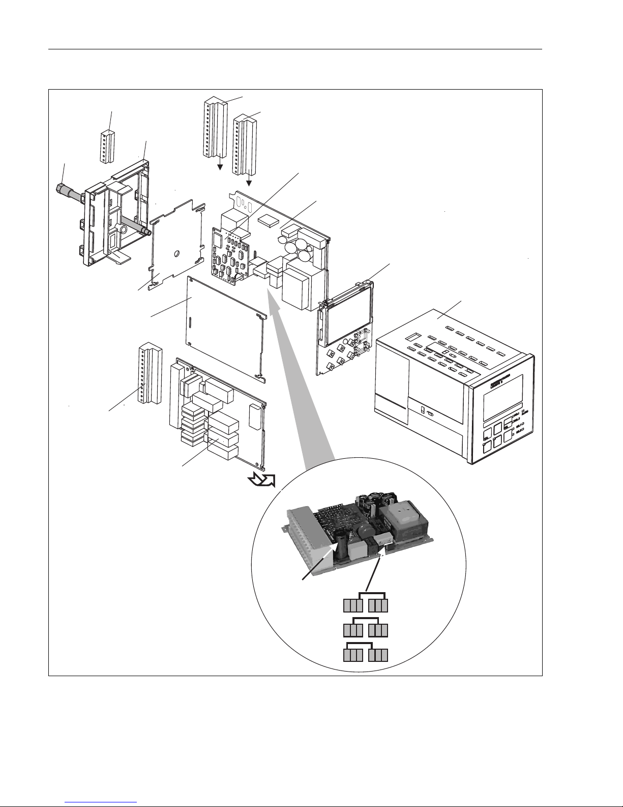
Repair Liquisys M CLM223F
68 Endress+Hauser
The exploded drawing contains the components and spare parts of the panel-mounted
instrument. You can take the spare parts and the corresponding order number from the
following section using the item numbers.
a0003612
Fig. 26: Exploded drawing
230V
100V
115V
400
345
340
420a
420b
320
240
15/20
40 ... 51
330
15/20
A
B
290
430
310
Page 69
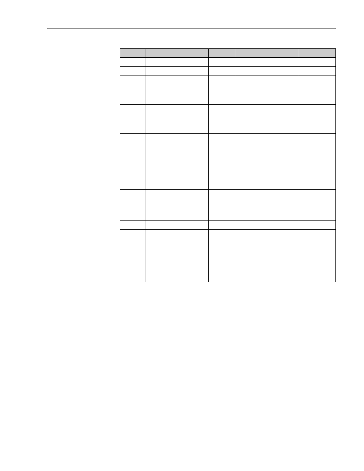
Liquisys M CLM223F Repair
Endress+Hauser 69
Item Kit description Name Function/contents Order number
15 Power unit (main module) LSGA 100 / 115 / 230 V AC 51500317
20 Power unit (main module) LSGD 24 V AC + DC 51500318
40 Central module cond.
(controller)
LSCH-S1 1 current output 51506379
50 Central module cond.
(controller)
LSCH-S2 2 current outputs 51506380
41 Central module ind.
(controller)
LSCH-S1 1 current output 51506385
51 Central module ind.
(controller)
LSCH-S2 2 current outputs 51506386
240 Conductivity transmitter (for
use in hazardous areas)
MKIC Cond. + temperature input 71161137
Conductivity transmitter MKIC Cond. + temperature input 71161133
290 Relay module LSR1-2 2 relays 51500320
310 Side panel Kit with 10 parts 51502124
310, 320,
340, 400
Housing mechanical parts Rear plate, side panel, end
frame, special screw
51501076
330, 400 Housing module Housing with front membrane,
sensory tappets, gasket, special
screw, tensioning dogs,
connection plates and
nameplates
51501075
345 Grounding terminal strip PE and screening connections 51501086
420a,
420b
Terminal strip set Complete terminal strip set, 51501203
430 Terminal strip Terminal strip for relay module 51501078
AFuse Part of power unit, item 15
B Choice of line voltage Position of jumper on power
unit, item 15 depending on line
voltage
Page 70

Repair Liquisys M CLM223F
70 Endress+Hauser
9.3 Replacing the central module
Generally, when a central module has been replaced, all data which can be changed are
set to the factory setting.
Proceed as described below if a central module is replaced:
1. If possible, note the customized settings of the device, such as:
– Calibration data
– Current assignment, main parameter and temperature
– Relay function selections
– Limit value/controller settings
– Concentration tables
– Monitoring functions
–ATC tables
– MRS settings
2. Disassemble the device as explained in the "Dismantling the panel-mounted instrument"
or "Dismantling the field instrument" section.
3. Use the part number on the central module to check whether the new module has the
same part number as the previous module.
4. Assemble the device with the new module.
5. Start up the device again and check the basic functions (e.g. measured value and
temperature display, operation via keyboard).
6. Enter the serial number:
– Read the serial number (“ser-no.”) off the nameplate of the device.
– Enter this number in the fields E115 (year, one-digit), E116 (month, one-digit), E117
(cons. number, four-digit).
– In the field E118, the complete number is displayed again so you can check it is
correct.
You can only enter the serial number for new modules with the serial number
0000. This can only be done once! For this reason, make sure the number
entered is correct before you confirm with ENTER!
Entry of an incorrect code will prevent the additional functions from being
enabled. An incorrect serial number can only be corrected at the factory!
Press ENTER to confirm the serial number or cancel the entry to enter the number
again.
7. Enter the release code for the Food Package in the "Service" menu.
8. Re-enter the customer device settings again.
9.4 Return
The device must be returned if repairs or a factory calibration are required, or if the wrong
device has been ordered or delivered. According to legal regulations, Endress+Hauser, as an
ISO-certified company, is required to follow certain procedures when handling returned
products that are in contact with medium.
To ensure swift, safe and professional device returns, please read the return procedures and
conditions on the internet site:
www.services.endress.com/return-material
9.5 Disposal
The device contains electronic components and must therefore be disposed of in accordance
with regulations on the disposal of electronic waste.
Please observe local regulations.
Page 71

Liquisys M CLM223F Accessories
Endress+Hauser 71
10 Accessories
10.1 Sensors
Condumax W CLS21
‣ Two-electrode sensor in fixed cable and plug-in head version
‣ Ordering according to product structure, www.products.endress.com/cls21
‣ Technical Information TI00085C/07/EN
Condumax W CLS30
‣ Two-electrode sensor with fixed cable
‣ With Pt 100 temperature sensor
‣ Cell constant k = 10 cm
-1
‣ Ordering according to product structure, see Technical Information TI00086C/07/EN
Indumax H CLS52
• Inductive conductivity sensor with short response time for food applications
• Ordering according to product structure, www.products.endress.com/cls52
• Technical Information TI00167C/07/EN
Indumax H CLS54
• Inductive conductivity sensor in certified, hygienic design for food, beverages, pharma and
biotechnology
• Ordering according to product structure, www.products.endress.com/cls54
• Technical Information TI00400C/07/EN
10.2 Connection accessories
CYK71 measuring cable
• Non-terminated cable for the connection of sensors (e.g. conductivity sensors) or the
extension of sensor cables
• Sold by the meter, order numbers:
– non-Ex version, black: 50085333
– Ex version, blue: 50085673
Extension cable CLK6
• For inductive conductivity sensors, for extension via the VBM junction box, sold by the
meter
• Order no.: 71183688
Junction box VBM
• For cable extension
• 10 terminals
• Cable entries: 2 x Pg 13.5 or 2 x NPT ½"
• Material: aluminum
• Ingress protection: IP 65 (i NEMA 4X)
• Order numbers:
– cable entries Pg 13.5: 50003987
– cable entries NPT ½": 51500177
10.3 Hardware add-ons
The add-ons can only be ordered by quoting the serial number of the device in question.
•Two-relay card
Order no. 51500320
Page 72

Accessories Liquisys M CLM223F
72 Endress+Hauser
10.4 Calibration solutions
Precision calibration solutions, acc. to SRM (Standard reference material) of NIST, error
limit ± 0.5 %, reference temperature 25 °C (77 °F), with temperature table
• CLY11-A, 74.0 μS/cm, 500 ml (0.132 Us.gal); order no. 50081902
• CLY11-B, 149.6 μS/cm, 500 ml (0.132 Us.gal); order no. 50081903
• CLY11-C, 1.406 mS/cm, 500 ml (0.132 Us.gal); order no. 50081904
• CLY11-D, 12.64 mS/cm, 500 ml (0.132 Us.gal); order no. 50081905
• CLY11-E, 107.0 mS/cm, 500 ml (0.132 Us.gal); order no. 50081906
Page 73

Liquisys M CLM223F Technical data
Endress+Hauser 73
11 Technical data
11.1 Input
Measured variables Conductivity, temperature
Measuring range
Cable specification
Cell constant
Temperature sensors Pt 100, Pt 1000, NTC 30K
Measuring frequency
Binary inputs
Conductivity (conductive): 0 to 400 mS/cm (uncompensated)
Conductivity (inductive): 0 to 2000 mS/cm (uncompensated)
Concentration: 0 to 9999 %
Temperature: -35 to +250 °C (-31 to +482 °F)
Cable length (conductive): conductivity: max. 100 m (328.1 ft) (CYK71)
Cable length (inductive): max 55 m (180.46 ft) (CLK5)
Cable resistance CYK71: 165 /km (conductivity measurement)
Adjustable cell constant: k = 0.0025 to 99.99 cm
-1
Conductivity, resistivity (conductive): 170 Hz to 2 kHz
Conductivity (inductive): 2 kHz
Voltage: 10 to 50 V
Power consumption: max. 10 mA
Page 74

Technical data Liquisys M CLM223F
74 Endress+Hauser
11.2 Output
Output signal 0/4 to 20 mA, galvanically separated, active
Signal on alarm 2.4 or 22 mA in case of an error
Load maximum 500
Linearization
transmission behaviour
Resolution max. 700 digits/mA
Min. distance for
0/4to20mA signal
Isolation voltage max. 350 V
RMS
/500 V DC
Overvoltage protection according to EN 61000-4-5
Auxiliary voltage output
Contact outputs
Limit contactor
Alarm
Conductivity:
Temperature:
adjustable
adjustable, 10 to 100 % of upper range value
Conductivity:
Measured value 0 to 19.99 μS/cm 2 μS/cm
Measured value 20 to 199.9 μS/cm20 μS/cm
Measured value 200 to 1999 μS/cm200 μS/cm
Measured value 2 to 19.99 mS/cm 2 mS/cm
Measured value 20 to 2000 mS/cm20 mS/cm
Concentration no minimum distance
Temperature 15 °C
Output voltage: 15 V ± 0.6
Output current: max. 10 mA
Switching current with ohmic load (cos = 1):max. 2 A
Switching current with inductive load
(cos = 0.4):
max. 2 A
Switching voltage: max. 250 V AC, 30 V DC
Switching power with ohmic load (cos = 1): max. 500 VA AC, 60 W DC
Switching power with inductive load
(cos = 0.4):
max. 500 VA AC, 60 W DC
Pickup/dropout delay: 0 to 2000 s
Function (selectable): Latching/momentary contact
Alarm threshold adjustment range: Conductivity, resistivity, concentration,
temperature, USP, EP: complete measuring
range
Alarm delay: 0 to 2000 s (min)
Page 75

Liquisys M CLM223F Technical data
Endress+Hauser 75
11.3 Power supply
Supply voltage Depending on ordered version:
100/115/230 V AC +10/-15 %, 48 to 62 Hz
24 V AC/DC +20/-15 %
Power consumption max. 7.5 VA
Mains protection Fine-wire fuse, medium-slow blow 250 V/3.15 A
11.4 Performance characteristics
Reference temperature 25 °C (77 °F); adjustable for the compensation of the medium temperature
Resolution
Maximum
measured error
1)
Repeatability
1
Temperature
compensation
Temperature offset ±5 °C; for the adjustment of the temperature display
Temperature: 0.1 °C
1) acc. to IEC 746-1, for nominal operating conditions
Conductivity:
Display: max. 0.5 % of measured value ± 4 digits
Conductivity signal output: max. 0.75 % of current output range
Temperature:
Display: max. 1.0 % of measuring range
Temperature signal output: max. 1.25 % of current output range
Conductivity: max. 0.2 % of measured value ± 2 digits
Range: -35 to +250 °C (-31 to +482 °F)
Types of compensation: linear, NaCl, table
Page 76

Technical data Liquisys M CLM223F
76 Endress+Hauser
11.5 Environment
Ambient temperature -10 to +55 °C (+14 to +131 °F)
Storage temperature –25 to +65 °C (-13 to +149 °F)
Electromagnetic
compatibility
Interference emission and interference immunity as per EN 61326-1:2006, EN 61326-23:2006
Ingress protection
Electrical safety according EN/IEC 61010-1:2001, Installation Category II, for use up to 2000 m above sea
level
CSA Apparatus with CSA General Purpose Approval are certified for indoor use.
Relative humidity 10 to 95%, non-condensing
Pollution degree The product is suitable for pollution degree 2.
11.6 Mechanical construction
Dimensions
Weight
Material
Terminals
Panel mounted instrument: IP 54 (front), IP 30 (housing)
Field instrument: IP 65 / tightness acc. to NEMA 4X
Panel-mounted instrument: L x W x D: 96 x 96 x 145 mm (3.78" x 3.78" x 5.71")
Installation depth: approx. 165 mm (6.50")
Panel-mounted instrument: max. 0.7 kg (1.54 lbs)
Housing: Polycarbonate
Front membrane: Polyester, UV-resistant
Cross section max. 2.5 mm
2
Page 77

Liquisys M CLM223F Technical data
Endress+Hauser 77
Page 78
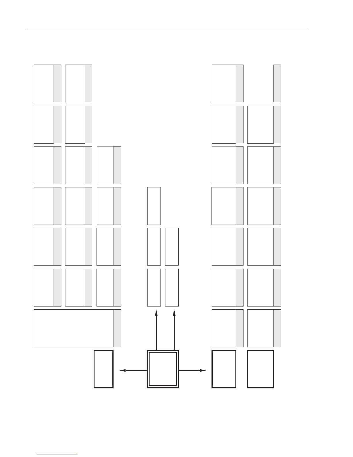
Appendix Liquisys M CLM223F
78 Endress+Hauser
12 Appendix
Operating matrix
a0003699-en
Store
calibration results
; no; newyes
Entry of value of
calibration solution
0.00 ... 20.00 %/K
a
2.10 %/K
Entry of
calibration temperature
(if B1 = fixed)
–35.0 ... +250.0 C
25.0 C°
°
Entry of correct
conductivity value of
calibration solution
0.0 µS/cm ... 9999 mS/cm
current meas. value
.
C133
Display of calculated
installation factor
0.10 ... 5.0
1.0
Display of
calibration status
o.k.;
E---
Function group
CALIBRATION
C
Calibration
InstF
= installation factor
Cellc
= cell constant
Airs = Airset
C1 (3)
C1 (2)
C1 (1)
C136
Residual coupling
Start calibration
current meas. value
Display of
residual coupling value
0.0 ... 80.0 µS/cm
C112
Display of
calibration status
o.k.;
E---
.
C113
Store
calibration results
; no; newyes
C114
C111
C132
C131
C134
C135
Function group
SETUP 1
MEAS. VALUE DISPLAY
Conductivity
and
temperature (°C)
A
Selection of operating mode
conc = concentration
cond = conductivity
A1
Selection of display
unit
µS/cm; mS/cm; S/cm;
µS/m; mS/m; S/m
auto;
Display of
conductivity (uncompensated)
concentration
A4
Selection of display format
(if A1 = conc)
X.xxx; ; XXX.x; XXXXXX.xx
Display of
conductivity
A3
Selection of display
unit
; mg/l; %; TDS; noneppm
Display of
conductivity and
temperature (°F)
Selection with PLUS key
Selection with MINUS key
Edit mode:
Code 22
E key
Edit mode:
Code 22
CAL key
A2
Error display
(up to 10 errors)
Err ---
Display of current
parameter set
(only with MRS)
Entry of cell constant
0.0025 ... ... 99.99 1/cm5.9
A5
ind.:Entry of installation
factor
01 ... ... 5.00
cond.: entry of cable
resistance
0.00 ... 99.99
1.00
W
A6
Entry of
measured value damping
(no damping)
1 ... 60
1
A7
Function group
SETUP 2
B
Selection of
temperature measurement
Pt1k (= Pt 1000)
NTC30 (= NTC 30 k
Pt100
W
)
fixed
B1
Selection of temperature
compensation type
none
NaCI = common salt
Tab=table 1 ... 4
lin = linear
.
B2
Entry of value
(if B2 = linear)
0.00 ... 20.00 %/K
a
2.10 %/K
B3
Entry of correct
process temperature
(if B1 = fixed)
25.0 °C
–35.0 °C ... +250.0 °C
B4
Temperature sensor
offset
(not if B1 = fixed)
–35.0 ... +250.0
Entry of actual temp.
°C
B5
Display of
temperature difference
(not if B1 = fixed)
0.0 °C
–5.0 ... 5.0 °C
B6
Store
calibration results
; no; newyes
C126
Entry of
calibration temperature
(if B1 = fixed)
–10.0 ... +150.0 C
25.0 C
.
°
°
C121
Entry of value of
calibration solution
0.00 ... 20.00 %/K
a
2.10 %/K
.
C122
Entry of correct
conductivity value of
calibration solution
0.0 mS/cm ... 9999 mS/cm
current meas. value
.
C123
Display of calculated
cell constant
0.1 ... 9.99 1/cm
C124
Display of
calibration status
o.k.;
E---
C125
Field for entry of
user setting
Page 79
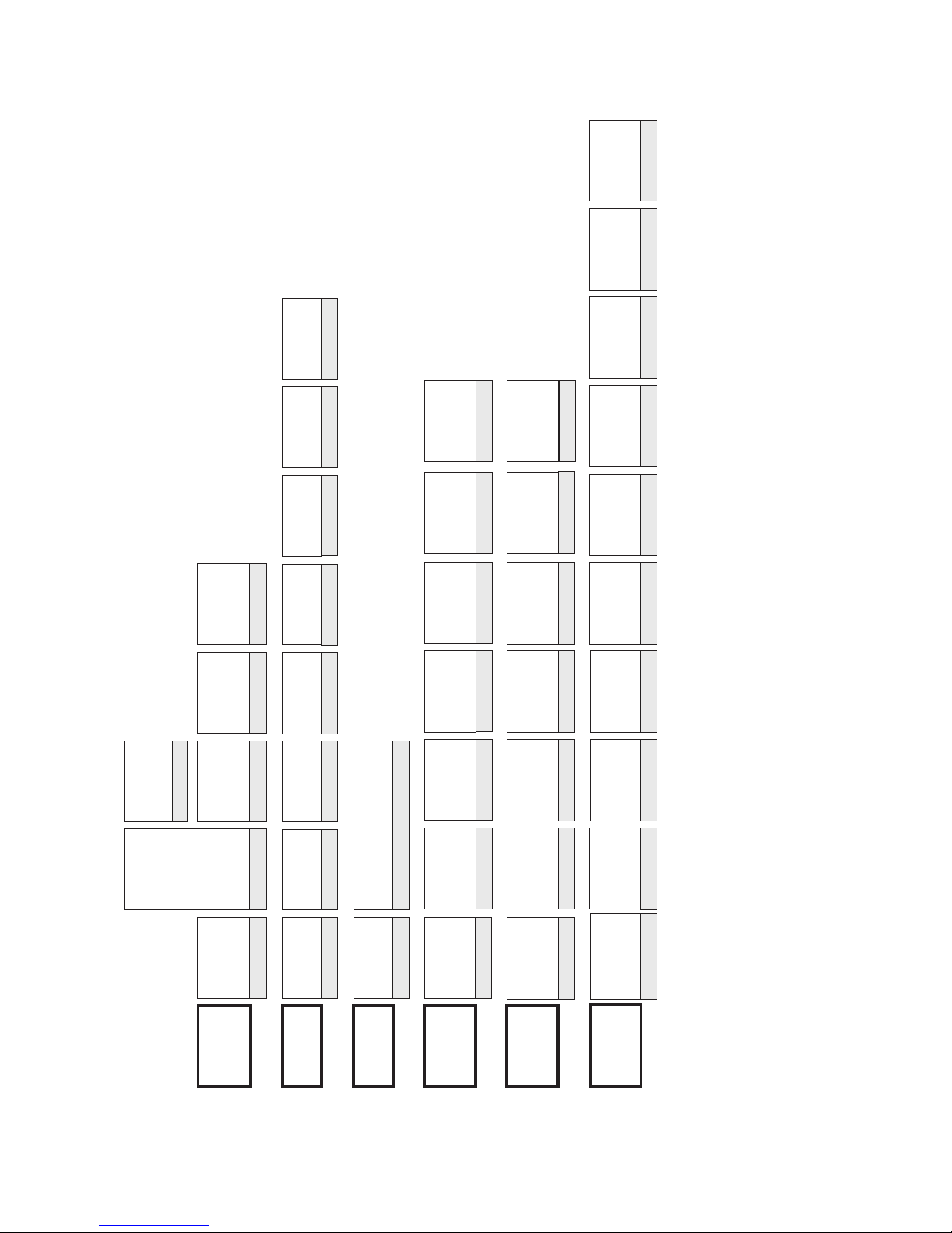
Liquisys M CLM223F Appendix
Endress+Hauser 79
a0003700-en
Function group
ALARM
F
Selection of
contact type
= steady contact
Fleet = fleeting contact
Stead
F1
Function group
CHECK
P
Selection of
unit for
alarm delay
mins;
F2
Entry of
alarm delay
... 2000 s (min)
(dependent on F2)
0
F3
Determination of
error current
2.4 mA
22 mA
F4
Selection of
error number
1 ... 255
1
F5
Set alarm contact to be
effective
;noyes
F6
Set error current
to be effective
yesno;
F7
F8
Select "next error"
or return to menu
R
next = next error
¬
Function group
OUTPUT
O
Selection of
Current output
; Out 2Out 1
O1
Selection of characteristic
sim = simulation
lin = linear
Entry of
simulation value
0 ... 22.00 mA
current value
O221
O2 (2)
O2 (1)
Selection of
current range
0-20 mA4-20 mA;
O211
O212
Entry of
20 mA value
entire meas. range
2000 mS/cm; 99.99 %;
150.0 °C
O213
Entry of
0/4 mA value
entire meas. range
0 µS/cm; 0 %; 0 °C
Ÿ
P2
PCS Alarm setting
(live check)
/1h/2h/4hoff
Monitoring limit
0.3 % of mean value
over time entered
Switch polarisation
detection on or off
onoff;
P1
R
Function group
RELAY
(only if MRS)
Selection of contact
to be configured
Rel2
Rel1
R1
Switch limit function for
selected contact offoron
on
off
R2
Selection of contact
switch-on point
entire meas. range
9999 mS/cm; 2000 mS/cm;
9999 %
Selection of contact
switch-off point
entire meas. range
9999 mS/cm; 2000 mS/cm;
9999 %
R3
R4
Pickup delay
setting
0 ... 2000 s
0s
Dropout delay
setting
0 ... 2000 s
0s
R5
Setting of alarm threshold
(as an absolute value)
entire meas. range
9999 mS/cm; 2000 mS/cm;
9999 %
R6
R7
Function group
ALPHA TABLE
Entry of number of
value pairs in table
1 ... 10
1
Selection of
tables
1 ... 4
(>1 only with MRS)
1
Selection of
table option
edit
read
T2
Multiplication factor
for concentration value
of a user table
0.5 ... 1.5
1
K2
T1
Selection of
table value pair
1 ... number from R3
asign
1
T4
Entry of
temperature coefficient
(y value)
0.00 ... 20.00 %/K
a
2.10 %/K
Entry of
temperature value
(x value)
–35.0 ... 250.0 °C
0.0 °C
Output
table status o.k.
noyes;
T5
T6
T7
T
T3
Function group
CONCENTRATION
K
Selection of active
concentration table
; H SO ;
H PO ; HNO
User ... 4
NaOH
1
24
34 3
K1
Selection of
tables
1 ... 4
1
K3
Selection of
table option
edit
read
K4
Entry of number
of value pairs in table
1 ... 16
1
Selection of
table value pair
1 ... number from K5
1
K5
Entry of
uncompensated
conductivity value
0.0 ... 9999 mS/cm
0.0 µS/cm
K6
Entry of associated
concentration value
0 ... 99.99 %
0.00 %
K7
Entry of associated
temperature value
0.0 °C
–35.0 ... +250.0 °C
K8
Output
table status o.k.
noyes;
K9
K10
Page 80
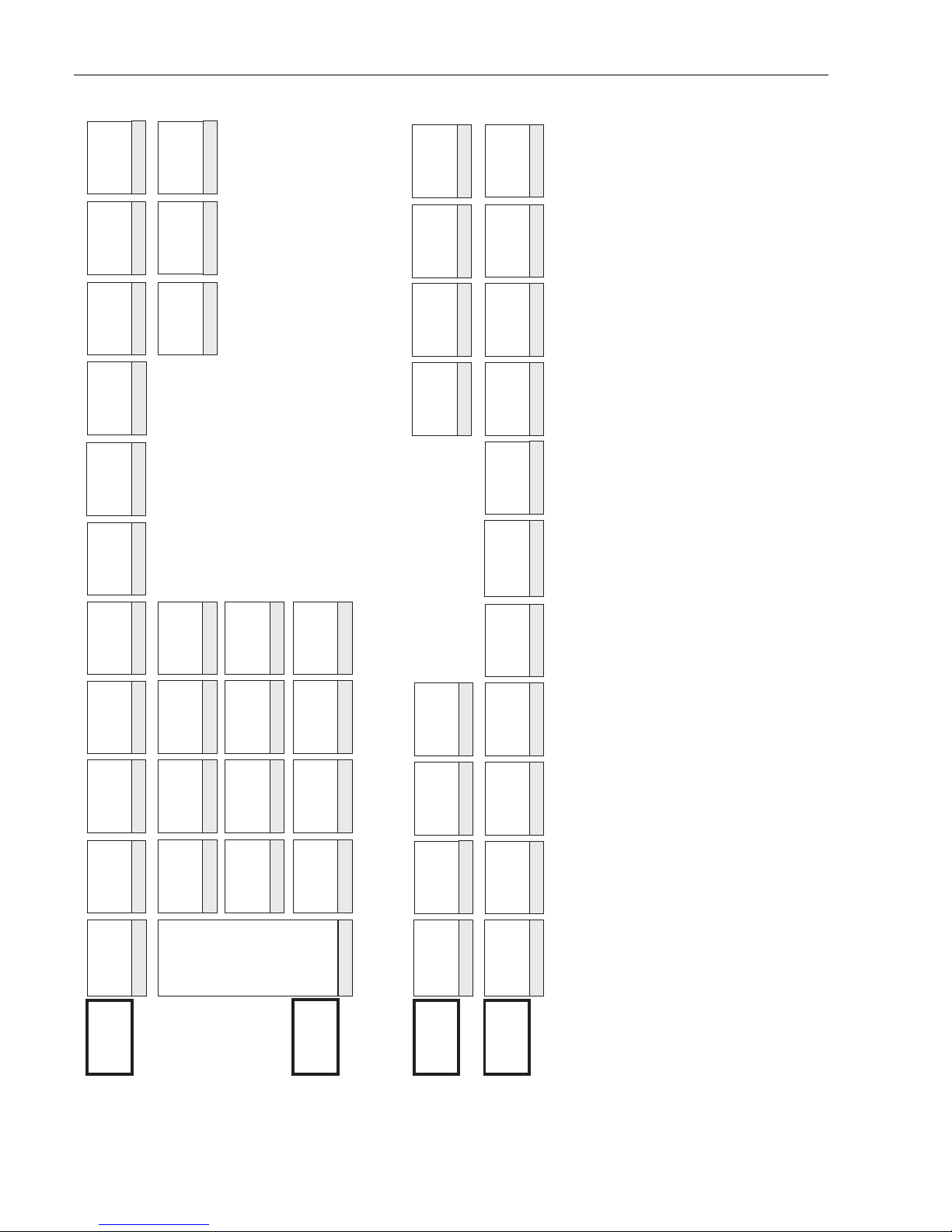
Appendix Liquisys M CLM223F
80 Endress+Hauser
a0003701-en
Function group
SERVICE
Function group
DETERMIN. OF
TEMPERATURE
COEFFICIENT
Function group
MEAS. RANGE
SWITCHING
(MRS)
S
D
M
Selection of
language
GER
ITA; FRA
ESP; NEL
ENG;
Entry of
compensated
conductivity
0 ... 9999
current value
Selection of binary
inputs for MRS
0 ... 2
2
Selection of
temperature compensation
none; NaCl;
Tab1 ... 4
if M4=cond
lin;
S1
D1
M1
M6
Software
version
SW version
E111
Hardware
version
HW version
E112
Display of
serial number
E113
Software
version
SW version
E121
Hardware
version
HW version
E122
Display of
serial number
E123
Software
version
SW version
E131
Hardware
version
HW version
E132
Display of
serial number
E133
HOLD configuration
none = no HOLD
Setup = during setup
CAL = dur. calibration
S+C = during setup
and calibration
Entry of
current temperature
–35 ... +250 °C
current value
Selection of
parameter set
1 ... 4 if M1=0
1 ... 2 if M1=1
1
Entry of measured value
for 0/4 mA value
cond.: 0 ... 2000 mS/cm
conc.: 0 ... 9999.999 %
Unit: A2
Format: A3
Entry of measured value
for 20 mA value
cond.: 0 ... 2000 mS/cm
conc.: 0 ... 9999.999 %
Unit: A2
Format: A3
Entry of limit
switch-on point
cond.: 0 ... 2000 mS/cm
conc.: 0 ... 9999.999 %
Unit: A2
Format: A3
Entry of limit
switch-off point
cond.: 0 ... 2000 mS/cm
conc.: 0 ... 9999.999 %
Unit: A2
Format: A3
S4
D3
M3
M8
Entry of
fixed value
(only if fixed)
0 ... 100 %
of 20 or 16 mA
0
Selection of
HOLD effect
fix = fixed value
froz = last value
Display of
uncompensated
conductivity
0 ... 9999
current value
Display of current
parameter set
1 ... 4 if M1=0
4
Entry of
alpha value
0 ... 20 %/K
2.1
S3
S2
D2
M2
M7
Manual HOLD
on
off
Entry of
HOLD dwell period
0 ... 999 s
10
Display of
alpha value determined
2.10 %/K
Selection of oper. mode
conc = concentration
1 ... 2 if M1=1
1 ... 4 if M1=2
cond = conductivity
Selection of medium
HSO;
H PO ; HNO ;
User 1 ... 2 if M1=1
User 1 ... 4 if M1=2
NaOH;
24
34 3
S5
D4
M4
M9
M5
M10
M12
M11
M13
S6
Display of
order number
S9
Display of
serial number
S8
S10
Function group
E+H SERVICE
E
Module selection
MainB =
mainboard
Trans =
transmitter
Contr = controller
E1(3)
E1(2)
E1(1)
Display of
module identification
E114
Display of
module identification
E124
Display of
module identification
E134
Instrument reset
Sens = sensor data;
Facty = factory settings
no;
Start
instrument test
;
Display
no
S11
M14
M15
Enter pickup delay
0 ... 2000 s
0s
Enter dropout delay
0 ... 2000 s
0s
Selection of contact
to be configured
Rel1
Rel2
Switch function of
contact offoron
On
Off
Enter SW upgrade
release code for
food package
0000
0000 ... 9999
S7
S9
Display of
serial number
S10
Instrument reset
Sens = sensor data;
Facty = factory settings
no;
Start
instrument test
;
Display
no
S11
S12
S13
Calibration of inner
resistance of conductive
sensors
off;
on;
Store calibration
yes;
no
new
S14
Status of resistance
determination
wait;
o. k.
E xxx.
Page 81

Liquisys M CLM223F
Endress+Hauser 81
Index
A
Access codes. . . . . . . . . . . . . . . . . . . . . . . . . . . . . . . . . . . . 23
Accessories . . . . . . . . . . . . . . . . . . . . . . . . . . . . . . . . . . . . . 71
Alarm . . . . . . . . . . . . . . . . . . . . . . . . . . . . . . . . . . . . . . 36, 74
Alarm contact. . . . . . . . . . . . . . . . . . . . . . . . . . . . . . . . . . . 16
Alpha table . . . . . . . . . . . . . . . . . . . . . . . . . . . . . . . . . . . . . 40
Ambient temperature . . . . . . . . . . . . . . . . . . . . . . . . . . . . 76
Automatic mode . . . . . . . . . . . . . . . . . . . . . . . . . . . . . . . . 22
Auxiliary voltage output . . . . . . . . . . . . . . . . . . . . . . . . . . 74
B
Binary inputs . . . . . . . . . . . . . . . . . . . . . . . . . . . . . . . . . . . 73
C
Cable specification. . . . . . . . . . . . . . . . . . . . . . . . . . . . . . . 73
Calibration . . . . . . . . . . . . . . . . . . . . . . . . . . . . . . . . . . . . . 53
CE mark. . . . . . . . . . . . . . . . . . . . . . . . . . . . . . . . . . . . . . . . . . 8
Cell constant. . . . . . . . . . . . . . . . . . . . . . . . . . . . . . . . . . . . 73
Check. . . . . . . . . . . . . . . . . . . . . . . . . . . . . . . . . . . . . . . . . . 37
Conductive sensors . . . . . . . . . . . . . . . . . . . . . . . . . . . 65
Inductive sensors . . . . . . . . . . . . . . . . . . . . . . . . . . . . . 66
Checking
Connections . . . . . . . . . . . . . . . . . . . . . . . . . . . . . . . . . 17
Function . . . . . . . . . . . . . . . . . . . . . . . . . . . . . . . . . . . . 25
Installation . . . . . . . . . . . . . . . . . . . . . . . . . . . . . . . . . . 11
Cleaning
pH/Redox sensors . . . . . . . . . . . . . . . . . . . . . . . . . . . . 63
Transmitter. . . . . . . . . . . . . . . . . . . . . . . . . . . . . . . . . . 62
Commissioning . . . . . . . . . . . . . . . . . . . . . . . . . . . . . . . . . 25
Concentration measurement . . . . . . . . . . . . . . . . . . . . . . 42
Connection diagram . . . . . . . . . . . . . . . . . . . . . . . . . . . . . 13
Contact outputs . . . . . . . . . . . . . . . . . . . . . . . . . . . . . . . . . 74
CSA . . . . . . . . . . . . . . . . . . . . . . . . . . . . . . . . . . . . . . . . . . . 76
CSA general purpose . . . . . . . . . . . . . . . . . . . . . . . . . . . . . . . 8
Current outputs . . . . . . . . . . . . . . . . . . . . . . . . . . . . . . . . . 35
D
Declaration of conformity. . . . . . . . . . . . . . . . . . . . . . . . . . . 8
Designated use. . . . . . . . . . . . . . . . . . . . . . . . . . . . . . . . . . . . 5
Diagnosis code . . . . . . . . . . . . . . . . . . . . . . . . . . . . . . . . . . 56
Dimensions. . . . . . . . . . . . . . . . . . . . . . . . . . . . . . . . . . . . . 76
Dismantling . . . . . . . . . . . . . . . . . . . . . . . . . . . . . . . . . . . . 67
Display. . . . . . . . . . . . . . . . . . . . . . . . . . . . . . . . . . . . . . . . . 18
Disposal. . . . . . . . . . . . . . . . . . . . . . . . . . . . . . . . . . . . . . . . 70
E
E+H Service
Menu
E+H Service. . . . . . . . . . . . . . . . . . . . . . . . . . . . . . . 49
Electrical connection . . . . . . . . . . . . . . . . . . . . . . . . . . . . . 12
Electrical icons . . . . . . . . . . . . . . . . . . . . . . . . . . . . . . . . . . . . 6
Electrical safety . . . . . . . . . . . . . . . . . . . . . . . . . . . . . . . . . 76
Electromagnetic compatibility . . . . . . . . . . . . . . . . . . . . . . . 5
EMC. . . . . . . . . . . . . . . . . . . . . . . . . . . . . . . . . . . . . . . . . . . 76
Environment. . . . . . . . . . . . . . . . . . . . . . . . . . . . . . . . . . . . 76
F
Factory settings . . . . . . . . . . . . . . . . . . . . . . . . . . . . . . . . . . 26
Freezing of outputs . . . . . . . . . . . . . . . . . . . . . . . . . . . . . . . 24
H
Hold function . . . . . . . . . . . . . . . . . . . . . . . . . . . . . . . . 24, 46
I
Icons
Electrical . . . . . . . . . . . . . . . . . . . . . . . . . . . . . . . . . . . . . . 6
Incoming acceptance. . . . . . . . . . . . . . . . . . . . . . . . . . . . . . . 7
Ingress protection . . . . . . . . . . . . . . . . . . . . . . . . . . . . . . . . 76
Input . . . . . . . . . . . . . . . . . . . . . . . . . . . . . . . . . . . . . . . . . . . 73
Installation . . . . . . . . . . . . . . . . . . . . . . . . . . . . . . . . . . . 9–11
Isolation voltage . . . . . . . . . . . . . . . . . . . . . . . . . . . . . . . . . 74
K
Key assignment . . . . . . . . . . . . . . . . . . . . . . . . . . . . . . . . . . 20
L
Limit contactor . . . . . . . . . . . . . . . . . . . . . . . . . . . . . . 38, 74
Linearization transmission behaviour . . . . . . . . . . . . . . . 74
Load . . . . . . . . . . . . . . . . . . . . . . . . . . . . . . . . . . . . . . . . . . . 74
M
Mains protection . . . . . . . . . . . . . . . . . . . . . . . . . . . . . . . . . 75
Maintenance . . . . . . . . . . . . . . . . . . . . . . . . . . . . . . . . . . . . 62
Entire measuring point. . . . . . . . . . . . . . . . . . . . . . . . . 62
Manual mode. . . . . . . . . . . . . . . . . . . . . . . . . . . . . . . . . . . . 22
Material . . . . . . . . . . . . . . . . . . . . . . . . . . . . . . . . . . . . . . . . 76
Maximum measured error . . . . . . . . . . . . . . . . . . . . . . . . . 75
Measured variables . . . . . . . . . . . . . . . . . . . . . . . . . . . . . . . 73
Measuring cable and sensor connection . . . . . . . . . . . . . 15
Measuring frequency . . . . . . . . . . . . . . . . . . . . . . . . . . . . . 73
Measuring range . . . . . . . . . . . . . . . . . . . . . . . . . . . . . . . . . 73
Measuring system. . . . . . . . . . . . . . . . . . . . . . . . . . . . . . . . . 9
Mechanical construction . . . . . . . . . . . . . . . . . . . . . . . . . . 76
Menu
Alarm . . . . . . . . . . . . . . . . . . . . . . . . . . . . . . . . . . . . . . . 36
Alpha table. . . . . . . . . . . . . . . . . . . . . . . . . . . . . . . . . . . 40
Check. . . . . . . . . . . . . . . . . . . . . . . . . . . . . . . . . . . . . . . . 37
Concentration . . . . . . . . . . . . . . . . . . . . . . . . . . . . . . . . 42
Current outputs . . . . . . . . . . . . . . . . . . . . . . . . . . . . . . . 35
MRS. . . . . . . . . . . . . . . . . . . . . . . . . . . . . . . . . . . . . . . . . 50
Relay . . . . . . . . . . . . . . . . . . . . . . . . . . . . . . . . . . . . . . . . 38
Service. . . . . . . . . . . . . . . . . . . . . . . . . . . . . . . . . . . . . . . 46
Setup 1 . . . . . . . . . . . . . . . . . . . . . . . . . . . . . . . . . . . . . . 30
Setup 2 . . . . . . . . . . . . . . . . . . . . . . . . . . . . . . . . . . . . . . 32
Temperature coefficient . . . . . . . . . . . . . . . . . . . . . . . . 41
Menu structure . . . . . . . . . . . . . . . . . . . . . . . . . . . . . . . . . . 24
MRS. . . . . . . . . . . . . . . . . . . . . . . . . . . . . . . . . . . . . . . . . . . . 50
N
Nameplate . . . . . . . . . . . . . . . . . . . . . . . . . . . . . . . . . . . . . . . 7
Page 82

Liquisys M CLM223F
82 Endress+Hauser
O
Operating elements . . . . . . . . . . . . . . . . . . . . . . . . . . . . . . 19
Operating modes. . . . . . . . . . . . . . . . . . . . . . . . . . . . . . . . . 23
Operation
Display . . . . . . . . . . . . . . . . . . . . . . . . . . . . . . . . . . . . . . 18
Operating concept. . . . . . . . . . . . . . . . . . . . . . . . . . . . . 22
Operating elements . . . . . . . . . . . . . . . . . . . . . . . . . . . 19
Operational safety . . . . . . . . . . . . . . . . . . . . . . . . . . . . . . . . 5
Output . . . . . . . . . . . . . . . . . . . . . . . . . . . . . . . . . . . . . . . . . 74
Output signal. . . . . . . . . . . . . . . . . . . . . . . . . . . . . . . . . . . . 74
Overvoltage protection. . . . . . . . . . . . . . . . . . . . . . . . . . . . 74
P
Performance characteristics . . . . . . . . . . . . . . . . . . . . . . . 75
Polarisation detection . . . . . . . . . . . . . . . . . . . . . . . . . . . . 37
Pollution degree . . . . . . . . . . . . . . . . . . . . . . . . . . . . . . . . . 76
Power consumption . . . . . . . . . . . . . . . . . . . . . . . . . . . . . . 75
Power supply . . . . . . . . . . . . . . . . . . . . . . . . . . . . . . . . . . . . 75
Product identification. . . . . . . . . . . . . . . . . . . . . . . . . . . . . . 7
Product safety . . . . . . . . . . . . . . . . . . . . . . . . . . . . . . . . . . . . 6
Q
Quick commissioning . . . . . . . . . . . . . . . . . . . . . . . . . . . . . 27
Quick setup . . . . . . . . . . . . . . . . . . . . . . . . . . . . . . . . . . . . . 27
Quick start-up . . . . . . . . . . . . . . . . . . . . . . . . . . . . . . . . . . . 27
R
Reference temperature . . . . . . . . . . . . . . . . . . . . . . . . . . . 75
Relative humidity . . . . . . . . . . . . . . . . . . . . . . . . . . . . . . . . 76
Relay contact configuration. . . . . . . . . . . . . . . . . . . . . . . . 38
Remote measuring range switching. . . . . . . . . . . . . . . . . 50
Repeatability1 . . . . . . . . . . . . . . . . . . . . . . . . . . . . . . . . . . . 75
Replacing the central module . . . . . . . . . . . . . . . . . . . . . . 70
Requirements for the personnel . . . . . . . . . . . . . . . . . . . . . 5
Resolution . . . . . . . . . . . . . . . . . . . . . . . . . . . . . . . . . . 74–75
Return. . . . . . . . . . . . . . . . . . . . . . . . . . . . . . . . . . . . . . . . . . 70
S
Scope of delivery . . . . . . . . . . . . . . . . . . . . . . . . . . . . . . . . . . 7
Service . . . . . . . . . . . . . . . . . . . . . . . . . . . . . . . . . . . . . . . . . 46
Setup 1 (conductivity) . . . . . . . . . . . . . . . . . . . . . . . . . . . . 30
Setup 2 (temperature) . . . . . . . . . . . . . . . . . . . . . . . . . . . . 32
Signal on alarm . . . . . . . . . . . . . . . . . . . . . . . . . . . . . . . . . . 74
Simulation of conductive sensors . . . . . . . . . . . . . . . . . . . 63
Simulation of inductive sensors . . . . . . . . . . . . . . . . . . . . 65
Spare parts. . . . . . . . . . . . . . . . . . . . . . . . . . . . . . . . . . . . . . 67
Storage temperature. . . . . . . . . . . . . . . . . . . . . . . . . . . . . . 76
Supply voltage . . . . . . . . . . . . . . . . . . . . . . . . . . . . . . . . . . . 75
Switching on . . . . . . . . . . . . . . . . . . . . . . . . . . . . . . . . . . . . 25
System configuration . . . . . . . . . . . . . . . . . . . . . . . . . 30–50
T
Technical data . . . . . . . . . . . . . . . . . . . . . . . . . . . . . . . 73–76
Temperature coefficient . . . . . . . . . . . . . . . . . . . . . . . . . . . 41
Temperature compensation. . . . . . . . . . . . . . . . . . . . . . . . 75
linear. . . . . . . . . . . . . . . . . . . . . . . . . . . . . . . . . . . . . . . . 32
NaCl. . . . . . . . . . . . . . . . . . . . . . . . . . . . . . . . . . . . . . . . . 32
with table . . . . . . . . . . . . . . . . . . . . . . . . . . . . . . . . . . . . 33
Temperature compensation with table . . . . . . . . . . . . . . 40
Temperature offset . . . . . . . . . . . . . . . . . . . . . . . . . . . . . . . 75
Temperature sensors . . . . . . . . . . . . . . . . . . . . . . . . . . . . . 73
Terminals . . . . . . . . . . . . . . . . . . . . . . . . . . . . . . . . . . . . . . . 76
Troubleshooting
Instrument specific errors . . . . . . . . . . . . . . . . . . . . . . 61
Process specific errors. . . . . . . . . . . . . . . . . . . . . . . . . . 58
System error messages . . . . . . . . . . . . . . . . . . . . . . . . . 56
Troubleshooting instructions. . . . . . . . . . . . . . . . . . . . . . . 56
U
Use
designated . . . . . . . . . . . . . . . . . . . . . . . . . . . . . . . . . . . . 5
W
Wall distance . . . . . . . . . . . . . . . . . . . . . . . . . . . . . . . . . . . . 30
Weight . . . . . . . . . . . . . . . . . . . . . . . . . . . . . . . . . . . . . . . . . 76
Wiring. . . . . . . . . . . . . . . . . . . . . . . . . . . . . . . . . . . . . . . . . . 12
Workplace safety. . . . . . . . . . . . . . . . . . . . . . . . . . . . . . . . . . 5
Page 83

Liquisys M CLM223F
Endress+Hauser 83
Page 84
www.addresses.endress.com
71230970
 Loading...