

Page 1
Products Solutions Services
TI00347F/00/EN/13.16
71310310
Technical Information
Liquiphant M
FTL51C
Vibronic
Point level switch for all kinds of liquids
with high corrosion-resistant coating
Application
The Liquiphant M is a point level switch for use in all liquids.
– for temperatures of –50 °C to 150 °C (-58 to 302 °F)
– for pressure up to 40 bar (580 psi)
– for viscosities up to 10000 mm
/s (cSt)
– for densities of 0.5 g/cm (SGU) or 0.7 g/cm(SGU)
The device functions reliably regardless of flow, turbulence, bubbles, foam, vibration,
solids content or buildup, making the Liquiphant an ideal substitute for float switches.
All the wetted parts of the sensor (process connection, extension pipe and tuning fork)
are coated in enamel or various synthetic materials, making the point level switch
suitable for applications in very aggressive liquids.
International approvals certify use in hazardous areas.
Your benefits
• Use in safety systems requiring functional safety to SIL2/SIL3 in accordance with IEC
61508/IEC 61511-1
• Optimally adapted to the process with a wide range of materials for corrosionresistant coating
• Large number of process connections to choose from
– Flanges for various standards
– Universal usage
• No adjustment: quick, low-cost startup
• No mechanically moving parts: no maintenance, no wear, long operating life
• FDA-approved material (PFA Edlon)
Page 2

Liquiphant M FTL51C
2 Endress+Hauser
Table of contents
Application. . . . . . . . . . . . . . . . . . . . . . . . . . . . . . . . . . . . .4
Point level detection . . . . . . . . . . . . . . . . . . . . . . . . . . . . . . . . . . . 4
Function and system design . . . . . . . . . . . . . . . . . . . . . .4
Measuring principle . . . . . . . . . . . . . . . . . . . . . . . . . . . . . . . . . . . 4
Modularity . . . . . . . . . . . . . . . . . . . . . . . . . . . . . . . . . . . . . . . . . . . 4
Electronic versions . . . . . . . . . . . . . . . . . . . . . . . . . . . . . . . . . . . . 5
Electronic version for density measurement . . . . . . . . . . . . . . . 5
Galvanic isolation . . . . . . . . . . . . . . . . . . . . . . . . . . . . . . . . . . . . . 5
Design . . . . . . . . . . . . . . . . . . . . . . . . . . . . . . . . . . . . . . . . . . . . . . . 5
Input . . . . . . . . . . . . . . . . . . . . . . . . . . . . . . . . . . . . . . . . . .5
Measured variable . . . . . . . . . . . . . . . . . . . . . . . . . . . . . . . . . . . . . 5
Measuring range (detection range) . . . . . . . . . . . . . . . . . . . . . . 5
Density . . . . . . . . . . . . . . . . . . . . . . . . . . . . . . . . . . . . . . . . . . . . . . 5
Electronic insert FEL51 (AC 2-wire) . . . . . . . . . . . . . . .6
Power supply . . . . . . . . . . . . . . . . . . . . . . . . . . . . . . . . . . . . . . . . . 6
Electrical connection . . . . . . . . . . . . . . . . . . . . . . . . . . . . . . . . . . . 6
Output signal . . . . . . . . . . . . . . . . . . . . . . . . . . . . . . . . . . . . . . . . . 6
Signal on alarm . . . . . . . . . . . . . . . . . . . . . . . . . . . . . . . . . . . . . . . 6
Connectable load . . . . . . . . . . . . . . . . . . . . . . . . . . . . . . . . . . . . . . 6
Electronic insert FEL52 (DC PNP). . . . . . . . . . . . . . . . . .8
Power supply . . . . . . . . . . . . . . . . . . . . . . . . . . . . . . . . . . . . . . . . . 8
Electrical connection . . . . . . . . . . . . . . . . . . . . . . . . . . . . . . . . . . . 8
Output signal . . . . . . . . . . . . . . . . . . . . . . . . . . . . . . . . . . . . . . . . . 8
Signal on alarm . . . . . . . . . . . . . . . . . . . . . . . . . . . . . . . . . . . . . . . 8
Connectable load . . . . . . . . . . . . . . . . . . . . . . . . . . . . . . . . . . . . . . 8
Electronic insert FEL54 (AC/DC with relay output). . .9
Power supply . . . . . . . . . . . . . . . . . . . . . . . . . . . . . . . . . . . . . . . . . 9
Electrical connection . . . . . . . . . . . . . . . . . . . . . . . . . . . . . . . . . . . 9
Output signal . . . . . . . . . . . . . . . . . . . . . . . . . . . . . . . . . . . . . . . . . 9
Signal on alarm . . . . . . . . . . . . . . . . . . . . . . . . . . . . . . . . . . . . . . . 9
Connectable load . . . . . . . . . . . . . . . . . . . . . . . . . . . . . . . . . . . . . . 9
Electronic insert FEL55 (8/16 mA) . . . . . . . . . . . . . . 10
Power supply . . . . . . . . . . . . . . . . . . . . . . . . . . . . . . . . . . . . . . . . 10
Electrical connection . . . . . . . . . . . . . . . . . . . . . . . . . . . . . . . . . . 10
Output signal . . . . . . . . . . . . . . . . . . . . . . . . . . . . . . . . . . . . . . . . 10
Signal on alarm . . . . . . . . . . . . . . . . . . . . . . . . . . . . . . . . . . . . . . 10
Connectable load . . . . . . . . . . . . . . . . . . . . . . . . . . . . . . . . . . . . . 10
Electronic insert FEL56 (NAMUR L-H edge). . . . . . . 11
Power supply . . . . . . . . . . . . . . . . . . . . . . . . . . . . . . . . . . . . . . . . 11
Electrical connection . . . . . . . . . . . . . . . . . . . . . . . . . . . . . . . . . . 11
Output signal . . . . . . . . . . . . . . . . . . . . . . . . . . . . . . . . . . . . . . . . 11
Signal on alarm . . . . . . . . . . . . . . . . . . . . . . . . . . . . . . . . . . . . . . 11
Connectable load . . . . . . . . . . . . . . . . . . . . . . . . . . . . . . . . . . . . . 11
Electronic insert FEL58 (NAMUR H-L edge). . . . . . . 12
Power supply . . . . . . . . . . . . . . . . . . . . . . . . . . . . . . . . . . . . . . . . 12
Electrical connection . . . . . . . . . . . . . . . . . . . . . . . . . . . . . . . . . . 12
Output signal . . . . . . . . . . . . . . . . . . . . . . . . . . . . . . . . . . . . . . . . 12
Signal on alarm . . . . . . . . . . . . . . . . . . . . . . . . . . . . . . . . . . . . . . 12
Connectable load . . . . . . . . . . . . . . . . . . . . . . . . . . . . . . . . . . . . . 12
Electronic insert FEL57 (PFM) . . . . . . . . . . . . . . . . . . 13
Power supply . . . . . . . . . . . . . . . . . . . . . . . . . . . . . . . . . . . . . . . . 13
Electrical connection . . . . . . . . . . . . . . . . . . . . . . . . . . . . . . . . . . 13
Output signal . . . . . . . . . . . . . . . . . . . . . . . . . . . . . . . . . . . . . . . . 14
Signal on alarm . . . . . . . . . . . . . . . . . . . . . . . . . . . . . . . . . . . . . . 14
Connectable load . . . . . . . . . . . . . . . . . . . . . . . . . . . . . . . . . . . . . 14
Electronic insert FEL50A (PROFIBUS PA) . . . . . . . . . 15
Power supply . . . . . . . . . . . . . . . . . . . . . . . . . . . . . . . . . . . . . . . . 15
Electrical connection . . . . . . . . . . . . . . . . . . . . . . . . . . . . . . . . . . 15
Output signal . . . . . . . . . . . . . . . . . . . . . . . . . . . . . . . . . . . . . . . . 16
Signal on alarm . . . . . . . . . . . . . . . . . . . . . . . . . . . . . . . . . . . . . . 16
Electronic insert FEL50D (density). . . . . . . . . . . . . . . 17
Power supply . . . . . . . . . . . . . . . . . . . . . . . . . . . . . . . . . . . . . . . . 17
Electrical connection . . . . . . . . . . . . . . . . . . . . . . . . . . . . . . . . . . 17
Signal on alarm . . . . . . . . . . . . . . . . . . . . . . . . . . . . . . . . . . . . . . 17
Adjustment . . . . . . . . . . . . . . . . . . . . . . . . . . . . . . . . . . . . . . . . . . 17
Operating principle . . . . . . . . . . . . . . . . . . . . . . . . . . . . . . . . . . . 18
Light signals . . . . . . . . . . . . . . . . . . . . . . . . . . . . . . . . . . . . . . . . . 18
Connection and function . . . . . . . . . . . . . . . . . . . . . . . 19
Connecting cables . . . . . . . . . . . . . . . . . . . . . . . . . . . . . . . . . . . . 19
Safety mode . . . . . . . . . . . . . . . . . . . . . . . . . . . . . . . . . . . . . . . . . 19
Switching time . . . . . . . . . . . . . . . . . . . . . . . . . . . . . . . . . . . . . . . 19
Switch-on behavior . . . . . . . . . . . . . . . . . . . . . . . . . . . . . . . . . . . 19
Performance characteristics . . . . . . . . . . . . . . . . . . . . 19
Reference operating conditions . . . . . . . . . . . . . . . . . . . . . . . . . 19
Maximum measured error . . . . . . . . . . . . . . . . . . . . . . . . . . . . . 19
Repeatability . . . . . . . . . . . . . . . . . . . . . . . . . . . . . . . . . . . . . . . . 19
Hysteresis . . . . . . . . . . . . . . . . . . . . . . . . . . . . . . . . . . . . . . . . . . . 19
Influence of medium temperature . . . . . . . . . . . . . . . . . . . . . . . 19
Influence of medium density . . . . . . . . . . . . . . . . . . . . . . . . . . . 19
Influence of medium pressure . . . . . . . . . . . . . . . . . . . . . . . . . . 19
Switching delay . . . . . . . . . . . . . . . . . . . . . . . . . . . . . . . . . . . . . . 19
Operating conditions . . . . . . . . . . . . . . . . . . . . . . . . . . 20
Installation instructions . . . . . . . . . . . . . . . . . . . . . . . . . . . . . . . 20
Examples of mounting . . . . . . . . . . . . . . . . . . . . . . . . . . . . . . . . 20
Orientation . . . . . . . . . . . . . . . . . . . . . . . . . . . . . . . . . . . . . . . . . . 22
Environment . . . . . . . . . . . . . . . . . . . . . . . . . . . . . . . . . 23
Ambient temperature range . . . . . . . . . . . . . . . . . . . . . . . . . . . 23
Storage temperature . . . . . . . . . . . . . . . . . . . . . . . . . . . . . . . . . . 23
Installation height as per IEC61010-1 Ed.3 . . . . . . . . . . . . . . 23
Climate class . . . . . . . . . . . . . . . . . . . . . . . . . . . . . . . . . . . . . . . . . 23
Degree of protection . . . . . . . . . . . . . . . . . . . . . . . . . . . . . . . . . . 23
Vibration resistance . . . . . . . . . . . . . . . . . . . . . . . . . . . . . . . . . . 23
Electromagnetic compatibility . . . . . . . . . . . . . . . . . . . . . . . . . . 23
Medium conditions . . . . . . . . . . . . . . . . . . . . . . . . . . . . 24
Medium temperature . . . . . . . . . . . . . . . . . . . . . . . . . . . . . . . . . 24
Thermal shock . . . . . . . . . . . . . . . . . . . . . . . . . . . . . . . . . . . . . . . 24
Page 3

3 Endress+Hauser
Liquiphant M FTL51C
Medium pressure pe . . . . . . . . . . . . . . . . . . . . . . . . . . . . . . . . . . 24
Test pressure . . . . . . . . . . . . . . . . . . . . . . . . . . . . . . . . . . . . . . . . 24
Pressure shock. . . . . . . . . . . . . . . . . . . . . . . . . . . . . . . . . . . . . . . 24
State of aggregation . . . . . . . . . . . . . . . . . . . . . . . . . . . . . . . . . . 24
Density . . . . . . . . . . . . . . . . . . . . . . . . . . . . . . . . . . . . . . . . . . . . . . 24
Viscosity . . . . . . . . . . . . . . . . . . . . . . . . . . . . . . . . . . . . . . . . . . . . 24
Solids content . . . . . . . . . . . . . . . . . . . . . . . . . . . . . . . . . . . . . . . . 24
Lateral loading capacity . . . . . . . . . . . . . . . . . . . . . . . . . . . . . . . 24
Mechanical construction . . . . . . . . . . . . . . . . . . . . . . . 25
Design . . . . . . . . . . . . . . . . . . . . . . . . . . . . . . . . . . . . . . . . . . . . . . 25
Dimensions (in mm) . . . . . . . . . . . . . . . . . . . . . . . . . . . . . . . . . . 26
Weights . . . . . . . . . . . . . . . . . . . . . . . . . . . . . . . . . . . . . . . . . . . . . 27
Material . . . . . . . . . . . . . . . . . . . . . . . . . . . . . . . . . . . . . . . . . . . . 28
Process connections . . . . . . . . . . . . . . . . . . . . . . . . . . . . . . . . . . . 28
Human interface . . . . . . . . . . . . . . . . . . . . . . . . . . . . . . 29
Electronic inserts . . . . . . . . . . . . . . . . . . . . . . . . . . . . . . . . . . . . . 29
Operating concept . . . . . . . . . . . . . . . . . . . . . . . . . . . . . . . . . . . . 29
Certificates and approvals . . . . . . . . . . . . . . . . . . . . . . 30
Certificates . . . . . . . . . . . . . . . . . . . . . . . . . . . . . . . . . . . . . . . . . . 30
CE mark . . . . . . . . . . . . . . . . . . . . . . . . . . . . . . . . . . . . . . . . . . . . . 30
RoHS . . . . . . . . . . . . . . . . . . . . . . . . . . . . . . . . . . . . . . . . . . . . . . . 30
RCM-tick mark . . . . . . . . . . . . . . . . . . . . . . . . . . . . . . . . . . . . . . . 30
EAC conformity . . . . . . . . . . . . . . . . . . . . . . . . . . . . . . . . . . . . . . 30
CRN approval . . . . . . . . . . . . . . . . . . . . . . . . . . . . . . . . . . . . . . . . 30
Pressure Equipment Directive 2014/68/EU (PED) . . . . . . . . . 30
Process seal according to ANSI/ISA 12.27.01 . . . . . . . . . . . . . 30
Other certificates . . . . . . . . . . . . . . . . . . . . . . . . . . . . . . . . . . . . . 30
Manufacturer declarations . . . . . . . . . . . . . . . . . . . . . . . . . . . . . 31
Use in hazardous zones . . . . . . . . . . . . . . . . . . . . . . . . . . . . . . . . 31
Combinations of coatings, housings and electronic inserts . . 31
Ordering information . . . . . . . . . . . . . . . . . . . . . . . . . . 33
Product structure Liquiphant M FTL51C . . . . . . . . . . . . . . . . . 33
Accessories . . . . . . . . . . . . . . . . . . . . . . . . . . . . . . . . . . . 36
Transparent cover . . . . . . . . . . . . . . . . . . . . . . . . . . . . . . . . . . . . 36
Cover with sight glass . . . . . . . . . . . . . . . . . . . . . . . . . . . . . . . . . 36
Weather protection cover . . . . . . . . . . . . . . . . . . . . . . . . . . . . . . 36
Documentation. . . . . . . . . . . . . . . . . . . . . . . . . . . . . . . . 37
Operating Instructions . . . . . . . . . . . . . . . . . . . . . . . . . . . . . . . . 37
Technical Information . . . . . . . . . . . . . . . . . . . . . . . . . . . . . . . . . 37
Functional safety (SIL) . . . . . . . . . . . . . . . . . . . . . . . . . . . . . . . . 37
Safety Instructions (ATEX) . . . . . . . . . . . . . . . . . . . . . . . . . . . . . 38
Safety Instructions (NEPSI) . . . . . . . . . . . . . . . . . . . . . . . . . . . . . 38
Control Drawings . . . . . . . . . . . . . . . . . . . . . . . . . . . . . . . . . . . . . 38
Page 4
Liquiphant M FTL51C
4 Endress+Hauser
Application
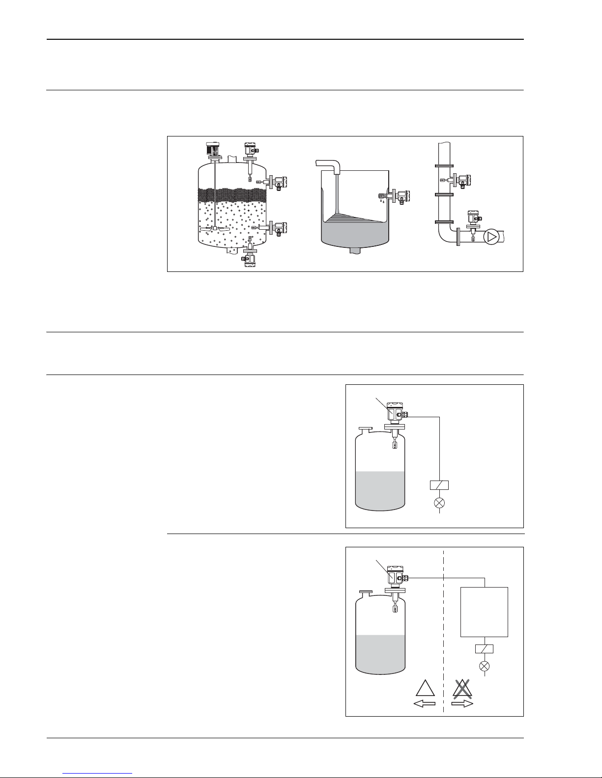
Point level detection Maximum or minimum detection in tanks or pipes containing all kinds of liquids, including use in
hazardous areas. Particularly suitable for very aggressive liquids that to high level of corrosion
protection.
L00-FTL51Cxx-11-05-xx-xx-001
Function and system design
Measuring principle The sensor's fork vibrates at its intrinsic frequency.
This frequency is reduced when covered with liquid. This change in frequency causes the point level
switch to switch.
Modularity
Point level switch
Liquiphant M FTL with electronic versions
FEL51, FEL52, FEL54
L00-FTL51Cxx-15-05-xx-xx-000
Point level switch
Liquiphant M FTL with electronic versions
FEL55, FEL56, FEL57, FEL58
for connecting to a separate switching unit
or an isolating amplifier FEL50A
for connecting to a PROFIBUS PA segment
L00-FTL51Cxx-15-05-xx-en-000
FEL51/52/54
…
FEL55/56/57/58/50A
Ex i
…
E
X
E
X
Switching unit
PLC
Isolating
amplifier
Segment
coupler
Page 5

Liquiphant M FTL51C
Endress+Hauser 5
Electronic versions FEL51:
Two-wire AC version;
Switches the load directly into the power supply circuit via an electronic switch.
FEL52:
Three-wire DC version;
Switches the load via the transistor (PNP) and separate connection e.g. in conjunction with
programmable logic controllers (PLCs), DI modules as per EN 61131-2.
FEL54:
Universal current version with relay output;
Switches the loads via 2 floating change-over contacts.
FEL55:
Signal transmission 16/8 mA on two-wire cabling e.g. in conjunction with programmable logic
controllers (PLCs), AI modules 4 to 20 mA as per EN 61131-2.
FEL56:
For separate switching unit; signal transmission L-H edge 0.6 to 1.0 / 2.2 to 2.8 mA
to EN 50227 (NAMUR) on two-wire cabling.
FEL58:
For separate switching unit; signal transmission H-L edge 2.2 to 3.5 / 0.6 to 1.0 mA
to EN 50227 (NAMUR) on two-wire cabling.
Checking of connecting cabling and other devices by pressing a key on the electronic insert.
FEL57:
For separate switching unit; PFM signal transmission;
Current pulses superposed on the power supply along the two-wire cabling.
Cyclical checking from the switching unit without changing levels.
FEL50A:
For connecting to PROFIBUS PA;
Cyclic and acyclic data exchange acc. to PROFIBUS-PA Profile 3.0; Discrete Input.
Electronic version for density
measurement
FEL50D:
For connecting to Density Computer FML621
Galvanic isolation FEL51, FEL52, FEL50A: between sensor and power supply
FEL54: between sensor and power supply and load
FEL55, FEL56, FEL57, FEL58, FEL50D: see connected switching unit
Design FTL51C: Flange, extension pipe and tuning fork are coated.
Input
Measured variable Level (limit value)
Measuring range (detection
range)
Depends on the mounting point or the length of the sensor with extension pipe.
Up to 3000 mm (118 in) for synthetic coating, up to 1200 mm (47.2 in) for enamel coating
Density Adjustment on the electronic insert > 0.5 g/cm
or > 0.7 g/cm (other on request)
Page 6
Liquiphant M FTL51C
6 Endress+Hauser
Electronic insert FEL51 (AC 2-wire)
Power supply Supply voltage: AC 19 to 253 V
Power consumption: < 0.83 W
Residual current consumption: < 3.8 mA
Short-circuit protection
Overvoltage protection FEL51: overvoltage category III
Electrical connection Two-wire AC connection
Output signal
Signal on alarm Output signal on power failure or in the event of damaged sensor: < 3.8 mA
Connectable load • Voltage drop via FEL51
12 V
• Residual current if electrical switch is blocked: 3.8 mA
• Load switched directly into the power supply circuit via the thyristor.
Transient (40 ms)
1.5 A, 375 VA at 253 V or 36 VA at 24 V (not short-circuit-proof)
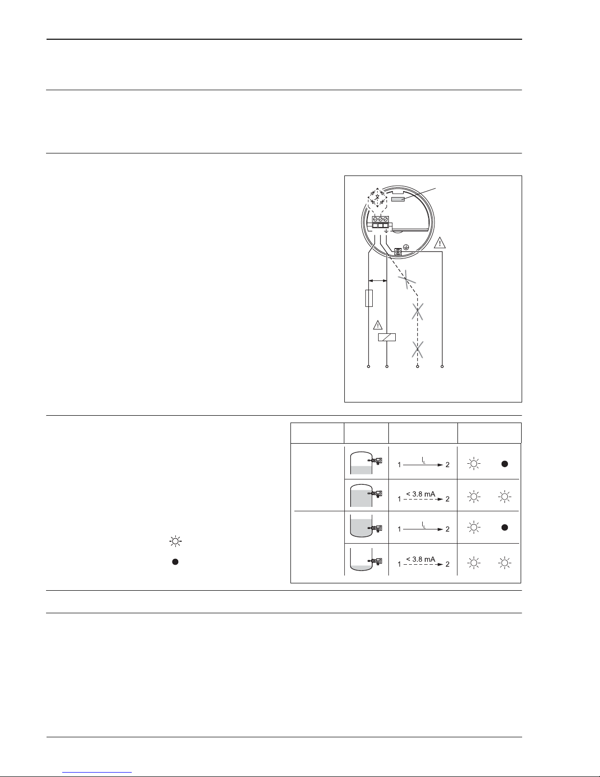
The load is switched via an electronic switch directly in the power circuit.
Always connect in series with a load!
Not suitable for connection to low-voltage PLC inputs!
Switches the load directly into the power supply
circuit via an electronic switch.
Always connect in series with a load!
Check the following:
• The residual current in blocked state
(up to 3.8 mA)
• That for low voltage
– the voltage drop across the load is such that
the minimum terminal voltage at the
electronic insert (19 V)
when blocked is not undershot.
– the voltage drop across the electronics when
switched through is observed (up to 12 V)
• That a relay cannot de-energize with holding
power below 3.8 mA.
If this is the case, a resistor should be
connected parallel to the relay. An RC module is
available under the part number: 71107226
• When selecting the relay, pay attention to the
holding power / rated power (see "Connectable
load")
L00-FTL5xxxx-04-05-xx-en-007
L1
U~ max. 253 V AC
50/60 Hz
NNPE
(Ground)
1A
min.
19 V
12
FEL51
*
R
*
External load R
be connectedmust
Safety mode Level Output signal LEDs
green red
I
L
< 3.8 mA
L00-FTL2xxxx-07-05-
xx-xx-000
= load current
(switched through)
= residual current
(blocked)
= lit
= unlit
L00-FTL5xxxx-04-05-xx-xx-001
MAX
MIN
Page 7
Liquiphant M FTL51C
Endress+Hauser 7
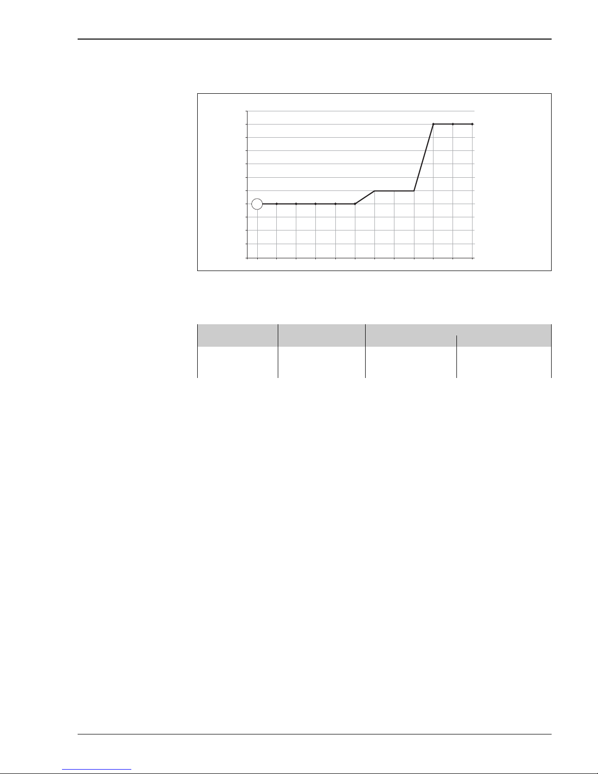
Selection guide for relays
TI00328F_001
Minimum nominal power of load
P/S nominal power in [W] / [VA]
U operating voltage in [V]
Relays with less nominal power can be operated via an RC module connected in parallel (optional).
2.7
2.5
2.3
2.1
1.9
1.7
1.5
1.3
1.1
0.9
0.7
0.5
20 24 27 43 48 53 60 110 121 207 230 253
P/S
U
P1
Position Operating voltage Nominal power
min. max.
P1
AC operation
24 V
110 V
230 V
> 1.3 VA
> 1.5 VA
> 2.5 VA
< 8.4 VA
< 38.5 VA
< 80.5 VA
Page 8
Liquiphant M FTL51C
8 Endress+Hauser
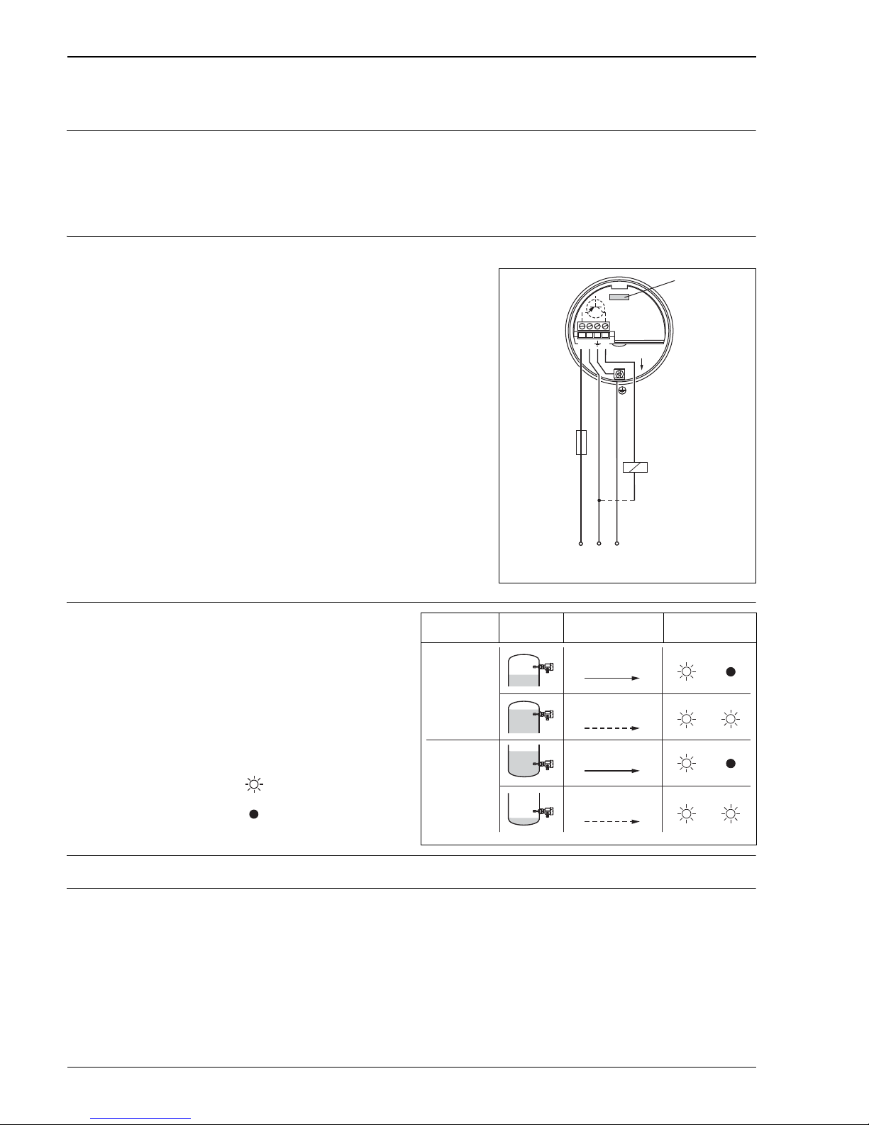
Electronic insert FEL52 (DC PNP)
Power supply Supply voltage: DC 10 to 55 V
Ripple:
1.7 V, 0 to 400 Hz
Current consumption: 15 mA
Power consumption: 0.83 W
Reverse polarity protection
Overvoltage protection FEL52: overvoltage category III
Electrical connection Three-wire DC connection
Output signal
Signal on alarm Output signal on power failure or in the event of damaged sensor: < 100 μA
Connectable load • Load switched via the transistor and separate PNP connection,
DC 55 V
•Load current
350 mA (pulsed overload and short-circuit protection)
• Residual current < 100 μA (with transistor blocked)
• Capacitance load 0.5 μF at 55 V, 1.0 μF at 24 V
• Residual voltage < 3 V (with transistor switched through);
Switches the load via the transistor (PNP) and
separate connection.
Preferably used with programmable logic
controllers (PLC),
DI modules as per EN 61131-2.
Positive signal at switching output of the
electronics (PNP); Output blocked on reaching
point level.
L00-FTL5xxxx-04-05-xx-xx-030
1 2 3
(+)
FEL52
L+
L–
–
0.5 A
U– 10…55 V DC
...
Relais,
PLC, ...
PE
(Ground)
R
Safety mode Level Output signal LEDs
green red
I
L
< 100 μA
L00-FTL2xxxx-07-05-
xx-xx-000
= load current
(switched through)
= residual current
(blocked)
= lit
= unlit
L00-FTL5xxxx-04-05-xx-xx-004
MAX
MIN
L+ +
1 3
L+ +
1 3
1 3
1 3
I
L
I
L
< 100 μA
< 100 μA
Page 9
Liquiphant M FTL51C
Endress+Hauser 9
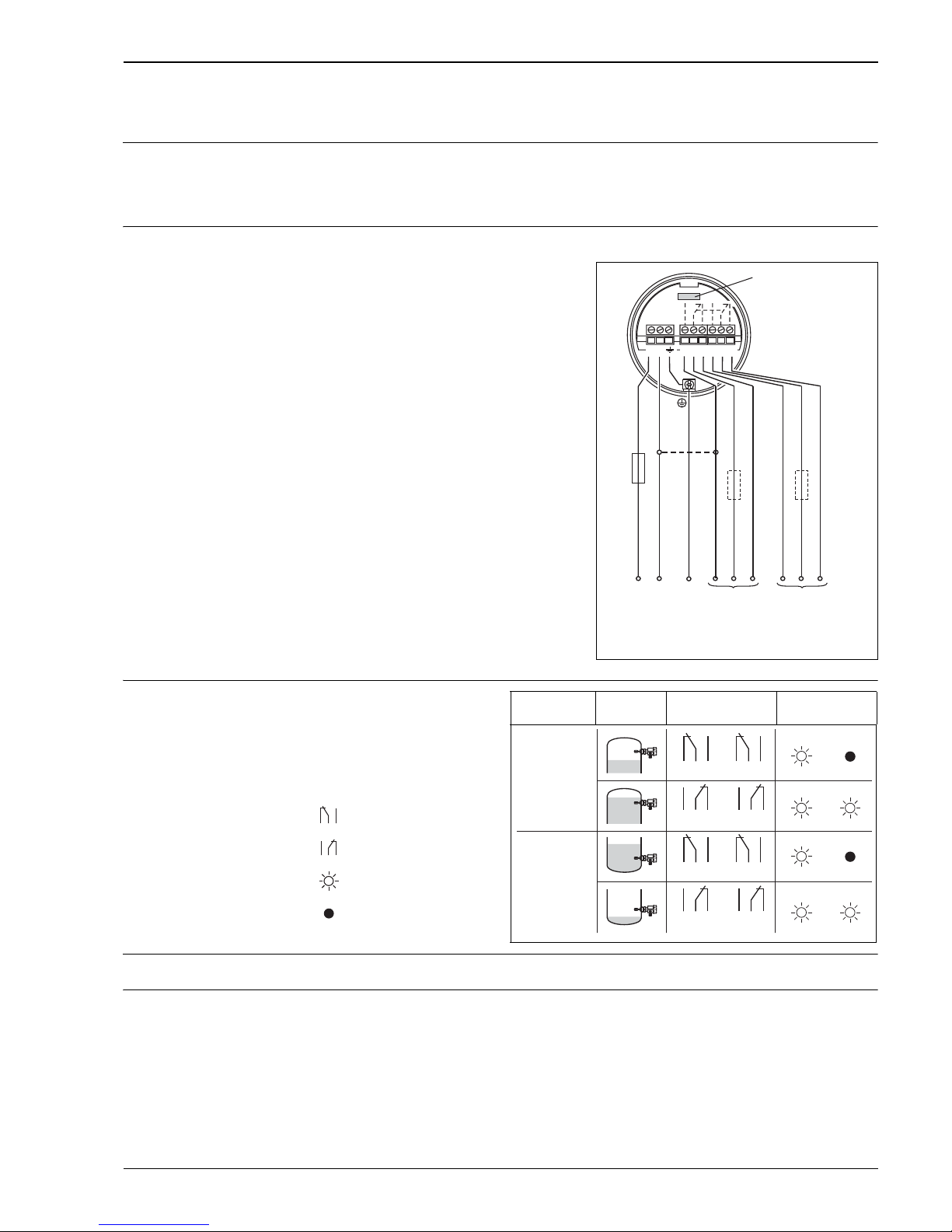
Electronic insert FEL54 (AC/DC with relay output)
Power supply Supply voltage: AC 19 to 253 V, 50/60 Hz or DC 19 to 55 V
Power consumption:
1.3 W
Reverse polarity protection
Overvoltage protection FEL54: overvoltage category III
Electrical connection Universal current connection with relay output
Output signal
Signal on alarm Output signal on power failure or in the event of damaged sensor: relay de-energized
Connectable load • Loads switched via 2 floating change-over contacts (DPDT)
•I~
6 A (Ex de 4 A), U~ AC 253 V; P~ 1500 VA, cos = 1, P~ 750 VA, cos > 0.7
•I%
6 A (Ex de 4 A) to DC 30 V , I% 0.2 A to 125 V
• When connecting a low-voltage circuit with double insulation according to IEC 1010, the following
applies: the sum of the voltages of the relay output and power supply is 300 V
• The electronic insert FEL52 DC-PNP is preferred for low DC load currents (e.g. when connecting to
a PLC)
• Relay contact material: silver/nickel AgNi 90/10
Power supply:
Please note the different
voltage ranges for AC and
DC.
Output:
When connecting an instrument with
high inductance, provide a spark arrester
to protect the relay contact.
A fine-wire fuse (depending on the
load connected) protects the relay
on short-circuiting.
Both relay contacts switch simultaneously.
* When jumpered, the relay
output works with NPN logic.
** See "Connectable load"
L00-FTL5xxxx-04-05-xx-xx-002
L1
L+
a
NO
a
NO
u
C
u
C
N
L–
r
NC
r
NC
0.5 A
PE
(Ground)
*
** **
12 678345
FEL54
U~ 19…253 V AC, 50/60 Hz
U– 19… 55 V DC
...
Safety mode Level Output signal LEDs
green red
L00-FTL2xxxx-07-05-
xx-xx-001
= relay energized
= relay de-energized
= lit
= unlit
L00-FTL5xxxx-04-05-xx-xx-005
MAX
MIN
354
354
687
687
354
354
687
687
Page 10
Liquiphant M FTL51C
10 Endress+Hauser
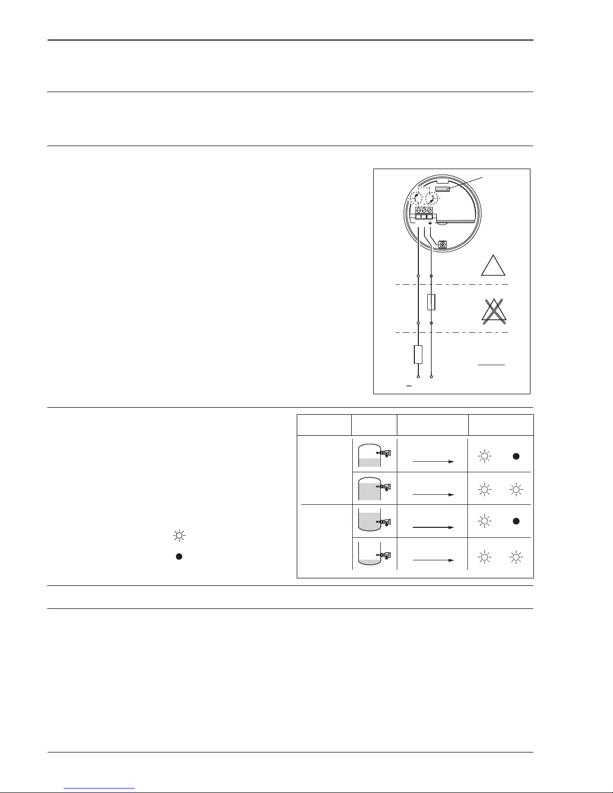
Electronic insert FEL55 (8/16 mA)
Power supply Supply voltage: DC 11 to 36 V
Power consumption: < 600 mW
Reverse polarity protection
Overvoltage protection FEL55: overvoltage category III
Electrical connection Two-wire connection for separate switching unit
Output signal
Signal on alarm Output signal on power failure or in the event of damaged sensor: < 3.6 mA
Connectable load • R = (U - 11 V) : 16.8 mA
• U = connection voltage: DC 11 to 36 V (in wet environments DC 11 to 35 V)
Example: PLC with 250 with 2-wire version
250 = (U – 11V) / 16.8 mA
4.2 [/] = U – 11 V
U = 15.2 V
For separate switching unit.
Signal transmission 16/8 mA on two-wire cabling.
For connection to programmable logic controllers
(PLC) for example, AI modules 4 to 20 mA to
EN 61131-2.
Output signal jump from high to low current on
point level.
Fuse required for non-Ex applications!
Only use power units with safe galvanic isolation (e.g.
SELV).
L00-FTL5xxxx-04-05-xx-en-000
1 2
FEL55
–
Ex ia
+
E
X
E
X
U 11...36 V DC
–
+
–
+
R
R =
max
U–11 V
16.8 mA
PLC/SPS,
AI-Modules, ...
F=T50mA
Safety mode Level Output signal LEDs
green red
~ 16 mA
~ 8 mA
L00-FTL2xxxx-07-05-
xx-xx-000
= 16 mA ± 5 %
= 8 mA ± 6 %
= lit
= unlit
L00-FTL5xxxx-04-05-xx-xx-006
MMAX
MIN
+
2 1
+
2 1
+
2 1
+
2 1
~16 mA
~8 mA
~8 mA
~16 mA
Page 11
Liquiphant M FTL51C
Endress+Hauser 11
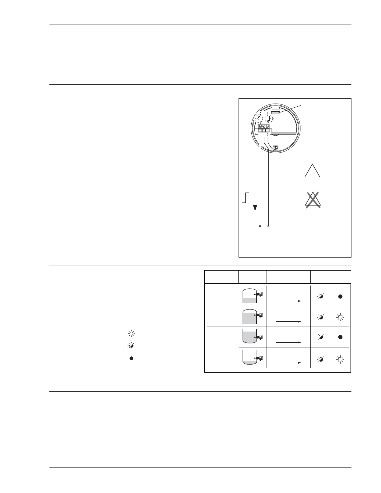
Electronic insert FEL56 (NAMUR L-H edge)
Power supply Supply voltage: DC 8.2 V ±20 %
Power consumption: < 6 mW at I < 1 mA; < 38 mW at I = 2.8 mA
Connection data interface: IEC 60947-5-6
Electrical connection Two-wire connection for separate switching unit
Output signal
Signal on alarm Output signal in the event of damaged sensor: > 2.2 mA
Connectable load • See Technical Data of the isolating amplifier connected according to IEC 60947–5–6 (NAMUR)
For connecting to isolating amplifiers according to
NAMUR (IEC 60947-5-6), e.g. FTL325N from
Endress+Hauser.
Output signal jump from low to high current on
point level.
(L–H edge)
Connecting to multiplexer:
Set clock time to min. 2 s.
L00-FTL5xxxx-04-05-xx-en-004
12
FEL56
–
EEx ia
H
L
+
E
X
E
X
I
Isolating amplifier
to
(NAMUR)
IEC 60947-5-6
Safety mode Level Output signal LEDs
green red
L00-FTL5xxxx-07-05-
xx-xx-002
= lit
= flashes
= unlit
L00-FTL5xxxx-04-05-xx-xx-003
MAX
MIN
+
2 1
+
2 1
+
2 1
+
2 1
0.6 …
1.0 mA
0.6 …
1.0 mA
2.2 …
2.8 mA
2.2 …
2.8 mA
Page 12
Liquiphant M FTL51C
12 Endress+Hauser
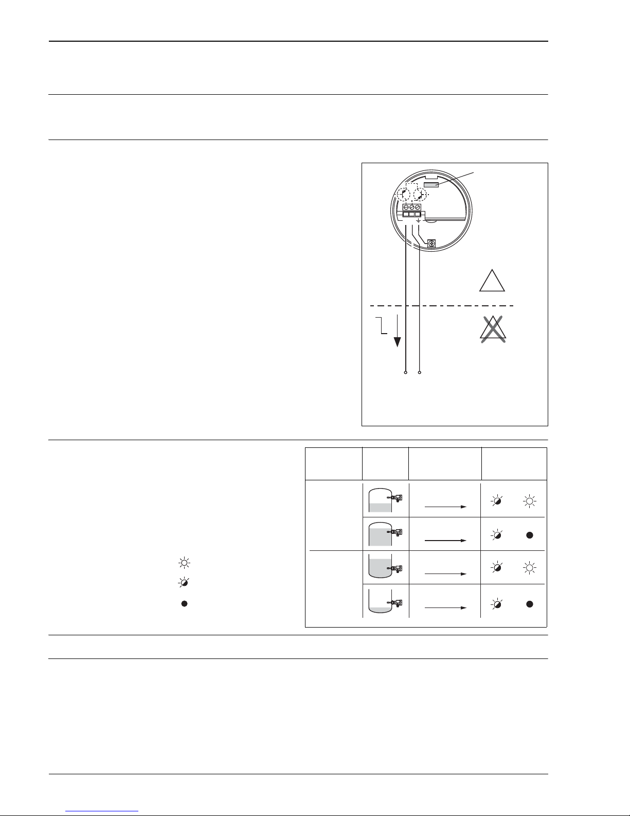
Electronic insert FEL58 (NAMUR H-L edge)
Power supply Supply voltage: DC 8.2 V ±20 %
Power consumption: < 6 mW at I < 1 mA; < 38 mW at I = 3.5 mA
Connection data interface: IEC 60947-5-6
Electrical connection Two-wire connection for separate switching unit
Output signal
Signal on alarm Output signal in the event of damaged sensor: < 1.0 mA
Connectable load • See Technical Data of the isolating amplifier connected according to IEC 60947–5–6 (NAMUR)
• Connection also to isolating amplifiers which have special safety circuits (I > 3.0 mA)
For connecting to isolating amplifiers
as per NAMUR (IEC 60947-5-6), e.g. FTL325N,
FTL375N from Endress+Hauser.
Output signal jump from high to low current on
point level.
(H–L edge)
Additional function:
Test key on the electronic insert.
Pressing the key breaks the connection to the
isolating amplifier.
!
Note!
In Ex–d applications, the additional function
can only be used if the housing is not exposed
to an explosive atmosphere.
Connecting to multiplexer:
Set clock time to min. 2 s.
L00-FTL5xxxx-04-05-xx-en-002
12
FEL58
–
EEx ia
H
L
+
E
X
E
X
I
Isolating amplifier
to
(NAMUR)
IEC 60947-5-6
Safety mode Level Output signal LEDs
green
yellow
L00-FTL5xxxx-07-05-
xx-xx-002
= lit
= flashes
= unlit
L00-FTL5xxxx-04-05-xx-xx-007
MAX
MIN
+
2 1
+
2 1
+
2 1
+
2 1
2.2 …
3.5 mA
2.2 …
3.5 mA
0.6 …
1.0 mA
0.6 …
1.0 mA
Page 13
Liquiphant M FTL51C
Endress+Hauser 13
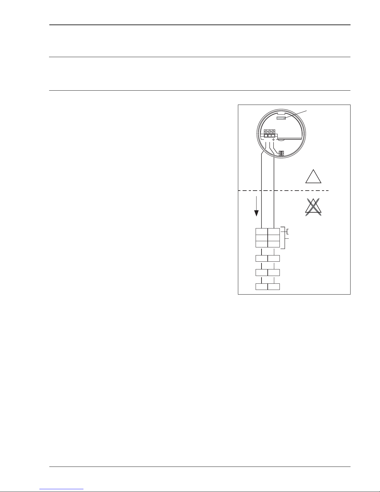
Electronic insert FEL57 (PFM)
Power supply Supply voltage: DC 9.5 to 12.5 V
Current consumption: 10 to 13 mA
Power consumption: < 150 mW
Reverse polarity protection
Electrical connection Two-wire connection for separate switching unit
The check is activated and monitored at the switching unit.
The twin-core connecting cable (instrument cable) with a cable resistance of 25 per core is
connected to the screw terminals (conductor cross-sections 0.5 to 2.5 mm / 0.02 to 0.1 in) in the
connection compartment. Protective circuits against reverse polarity, HF influences and overvoltage
peaks are installed.
Maximum cable length up to 1000 m (3281 ft).
A shielded connecting cable is recommended in the event of strong electromagnetic interference. Here
the shielding must be connected to the sensor and the power supply.
For connecting to Endress+Hauser switching units
Nivotester FTL320, FTL325P, FTL370, FTL372,
FTL375P (also with proof test).
Output signal jump of the PFM signal from high to
low frequency when sensor is covered. Switching
between minimum/maximum safety in the
Nivotester.
Additional function “cyclical checking”:
After interruption of the power supply,
a test cycle is activated
which checks the sensor and electronics
without any change in level.
Approved for overfill protection acc. to WHG
(German Water Resources Act).
The following can be switched at the electronic
insert:
– Standard
(STD):
simulation approx. 8 s
tuning fork exposed – covered – exposed.
For proof testing, the Nivotester tests the
sensor's level notification function.
– Extended (EXT):
Simulation approx. 41 s: tuning fork exposed –
covered – alarm – exposed.
For proof testing, the Nivotester tests the
sensor's level notification function and fault
notification (alarm) function.
L00-FTL5xxxx-04-05-xx-en-003
– +
78
33 34
37 38
d4 d2
z6d6
z4 z2
PFM
50 /
150 Hz
E
X
E
X
12
FEL57
EEx ia
Nivotester
FTL320
FTL325P 1CH
FTL325P 3CH
FTL370/372
FTL375P 1CH
Input 1
FTL372
FTL375P 2CH
Input 2
FTL375P 3CH
Input 3
Page 14
Liquiphant M FTL51C
14 Endress+Hauser
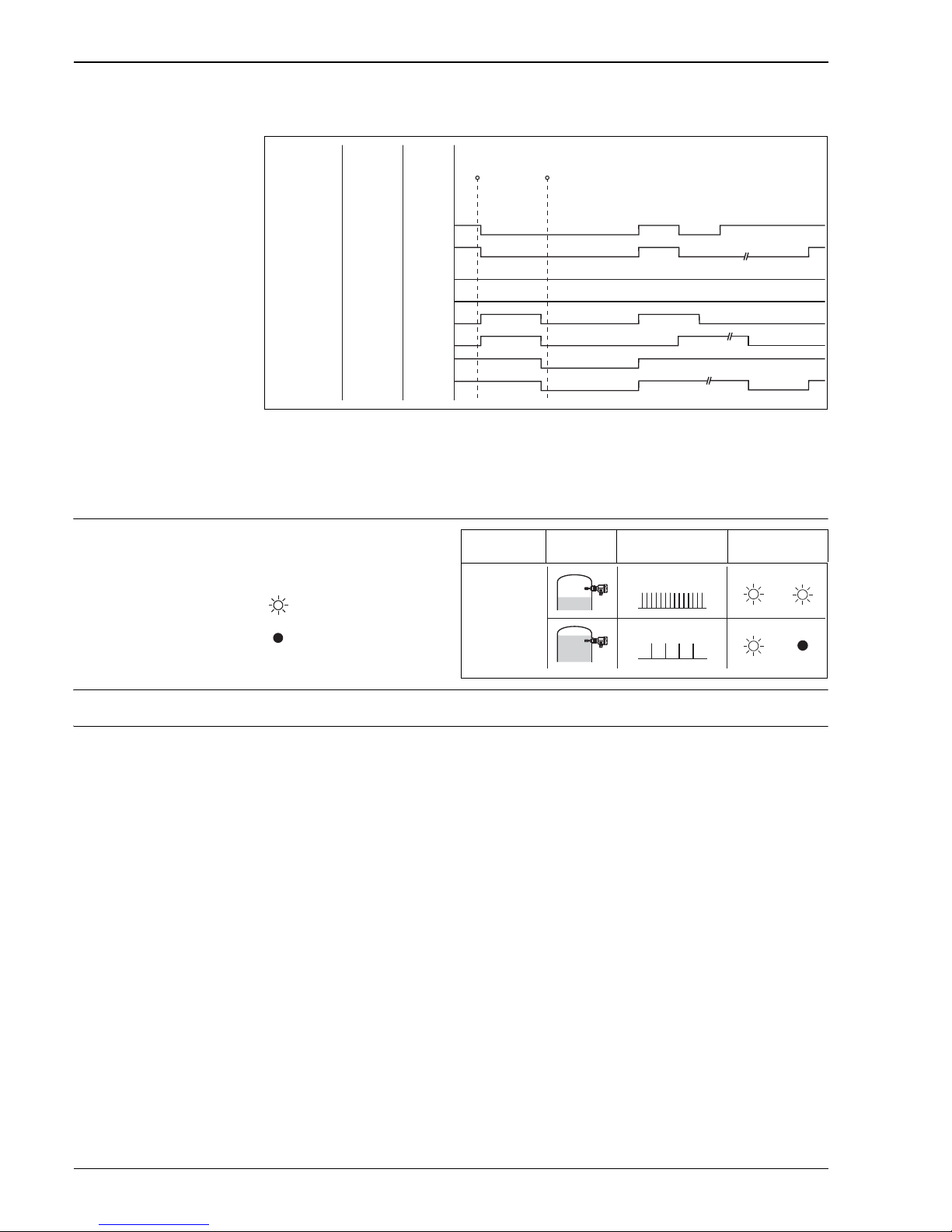
Switching behavior of the connected device:
Please note this switching response and function of the plant especially when replacing a Liquiphant
incorporating electronic insert EL17Z or FEL37 with a Liquiphant M incorporating electronic insert
FEL57.
Output signal
Signal on alarm Output signal on power failure or in the event of damaged sensor: 0 Hz
Connectable load • Floating relay contacts in the connected switching unit Nivotester FTL325P, FTL375P
• For contact load, see the Technical Data of the switching unit.
L00-FTL5xxxx-05-05-xx-en-000
* De-energized on power supply failure
Fail-safe mode
set at
switching unit
MAX
MAX
MAX
MAX
MIN
MIN
MIN
MIN
Setting
at FEL57
STD
EXT
STD
EXT
STD
EXT
STD
EXT
Fork
free
free
covered
covered
free
free
covered
covered
Switching status of relay in switching unit
on = energised off = de-energised
Te st start End of t
est start
(power off) (power on)
> 3 s
on
on
off
off
off
off
on
on
off
off
off
off
~ 3 s on
~ 3 s on
~ 3 s on
~ 3 s on
~ 5 s off
~ 5 s off
off
off
~ 5 s off
~ 7 s off
~ 5 s off
~ 5 s off
~ 2 s on
~ 2 s on
~ 3 s on
on
~ 35 s on
~ 3 s off
~ 2 s off
~ 35 s off
off
~ 30 s on
on
on
on
off
Safety mode Level Output signal
(PFM)
LEDs
green yellow
L00-FTL2xxxx-07-05-
xx-xx-000
= lit
= unlit
L00-FTL5xxxx-04-05-xx-xx-008
150 Hz
50 Hz
Page 15
Liquiphant M FTL51C
Endress+Hauser 15
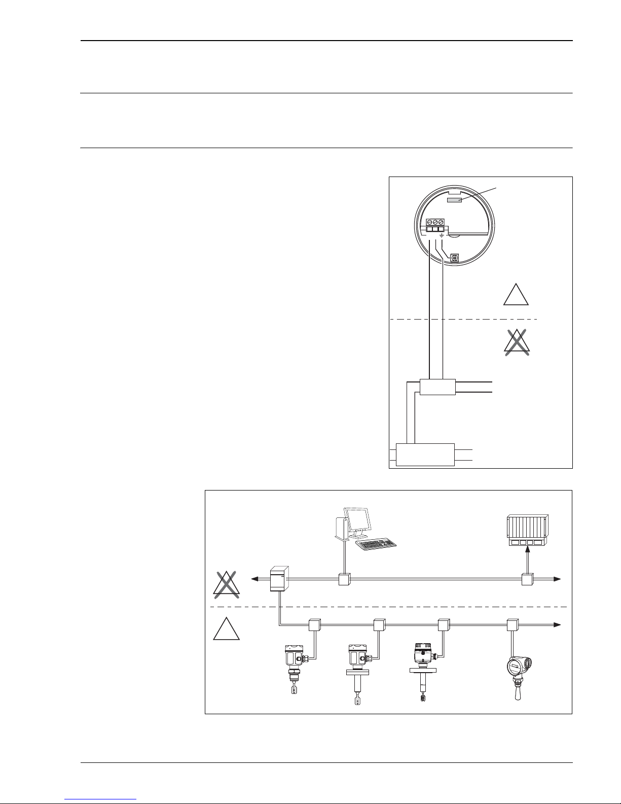
Electronic insert FEL50A (PROFIBUS PA)
Power supply Bus voltage: DC 9 to 32 V
Bus current:
• 12.5 mA +/– 1.0 mA (software version: 01.03.00, hardware version: 02.00)
• 10.5 mA +/– 1.0 mA (software version: 01.03.00, hardware version: 01.00)
Electrical connection Two-wire connection for power supply and data transfer
L00-FTL5xxxx-04-05-xx-xx-100
For connecting to PROFIBUS PA
Additional functions:
– Digital communication enables the
representation, reading and editing
of the following parameters:
Fork frequency, switch-on frequency,
switch-off frequency, switch-on time and
switch-off time, status, measured value, density
change
– Matrix locking possible
– Switch to WHG mode possible
(WHG approval)
– For a detailed description, see BA00198F
L00-FTL5xxxx-04-05-xx-en-005
PA– PA+
PROFIBUS PA
–
–
–
–
E
X
E
X
U– 9…32 V DC
...
12
FEL50A
Segment coupler
PLC
PROFIBUS DP
PROFIBUS PA
E
X
E
X
PC
Proficard Profiboard/
Segment plercou
Page 16
Liquiphant M FTL51C
16 Endress+Hauser
Output signal
Signal on alarm • Failure information can be opened using the following interfaces:
Yellow LED flashing, status code, diagnostic code; see BA00198F
Setting Level LEDs
green yellow
FEL50A
L00-FTL2xxxx-07-05-
xx-xx-000
not
inverted
L00-FTL5xxxx-04-05-xx-xx-009
OUT_D = 0
PA bus signal
OUT_D = 1
PA bus signal
= lit inverted
OUT_D = 0
PA bus signal
= unlit
OUT_D = 1
PA bus signal
Page 17
Liquiphant M FTL51C
Endress+Hauser 17
Electronic insert FEL50D (density)
Power supply Frequency range: 300 to 1500 Hz
Signal level: 4 mA
Pulse height: 16 mA
Pulse width: 20 μS
Electrical connection
Signal on alarm Output signal on power failure or in the event of damaged sensor: 0 Hz
Adjustment In the Liquiphant M modular system, the option of an adjustment is also provided in addition to the
electronics
(see feature 60: "Accessories").
There are three types of adjustment:
Standard adjustment (see ordering information for additional options, basic version A)
• Here, two fork parameters are determined to describe the sensor characteristics,
indicated in the adjustment report and provided with the product.
These parameters must be transmitted to the Density Computer FML621.
Special adjustment (see ordering information for additional options, special adjustment, density H
2
O
(K) or special adjustment, density H
2
O with 3.1 certificate (L))
• Here, three fork parameters are determined to describe the sensor characteristics, indicated in the
adjustment report and provided with the product.
These parameters must be transmitted to the Density Computer FML621.
Greater accuracy is achieved with this type of adjustment (see also "Performance characteristics").
Field adjustment
• During field adjustment, a density value actually determined by the customer is entered and the
system is automatically adjusted to this value (wet adjustment).
!
Note!
More information on Liquiphant M Density is available in Technical Information TI00420F. This
document is available for download at www.endress.com => Download.
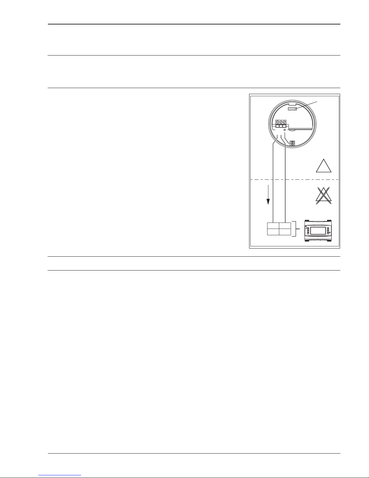
Two-wire connection at Density Computer FML621
For connecting to the density and concentration computer
FML621.
The output signal is based on pulse technology. With the
aid of this signal, the fork frequency is constantly
forwarded to the switching unit.
"
Caution!
Operation with other switching units,
such as FTL325P, is not permitted.
This electronic insert cannot be installed in devices
that were originally used as a point level
switch.
TI420Fen004
– +
10 82
112 182
E
X
E
X
12
FEL50D
EEx ia
FML621
Endress+Hauser
On
FML621
–
+
Impuls
Page 18
Liquiphant M FTL51C
18 Endress+Hauser
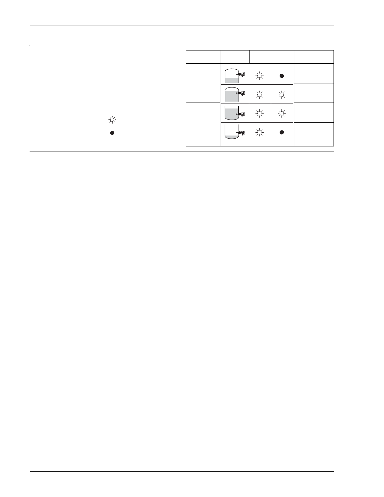
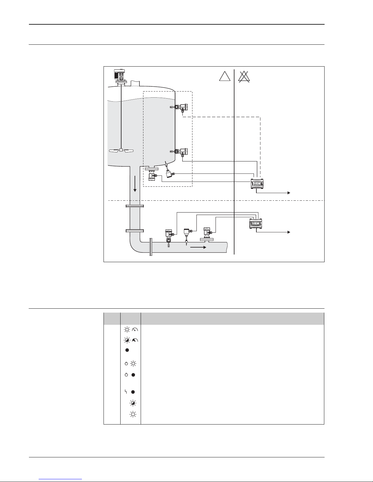
Operating principle Measuring the density of a liquid medium in pipes and tanks. Also suitable for use in hazardous areas,
and preferably for applications in the chemical and food industry.
TI420Fxx016
* Pressure and temperature information required depending on the application.
1. Liquiphant M sensor with electronic insert FEL50D (pulse output);
2. Temperature sensor (e.g. 4 to 20 mA output);
3. Pressure transmitter (4 to 20 mA output);
4. Liquiphant density and concentration computer FML621 with display and operating unit
Light signals
Endress+Hauser
On
RMM621
*
*
Endress+Hauser
On
RMM621
1. 2. 3. 4.
PLC/SPS
PLC/SPS
FML621
FML621
E
X
E
X
LED Symbol Information
Yellow Measurement valid
Unstable process situation
Maintenance required
Green Power on
Power off
Red No fault
Maintenance required
Device failure
Page 19
Liquiphant M FTL51C
Endress+Hauser 19
Connection and function
Connecting cables • Electronic inserts: cross-section 2.5 mm (14 AWG); strand in ferrule as per DIN 46228
• Protective ground in housing: cross-section
2.5 mm
(14 AWG)
• External equipotential bonding connection on housing: cross-section 4 mm(12 AWG)
Safety mode Minimum/maximum residual current safety selectable on electronic insert
(with FEL57 on Nivotester only)
MAX = maximum safety:
The output switches to the power fail response when the fork is covered
For use with overfill protection for example
MIN = minimum safety:
The output switches to the power fail response when the fork is exposed
For use with dry running protection for example
Switching time When fork is covered: approx. 0.5 s
When fork is exposed: approx. 1.0 s
Additionally configurable for PROFIBUS PA: 0.5 to 60 s
Other switching times available on request.
Switch-on behavior When switching on the power supply, the output assumes the alarm signal.
After
3 s it assumes the correct switching mode (exception: FEL57)
Performance characteristics
Reference operating
conditions
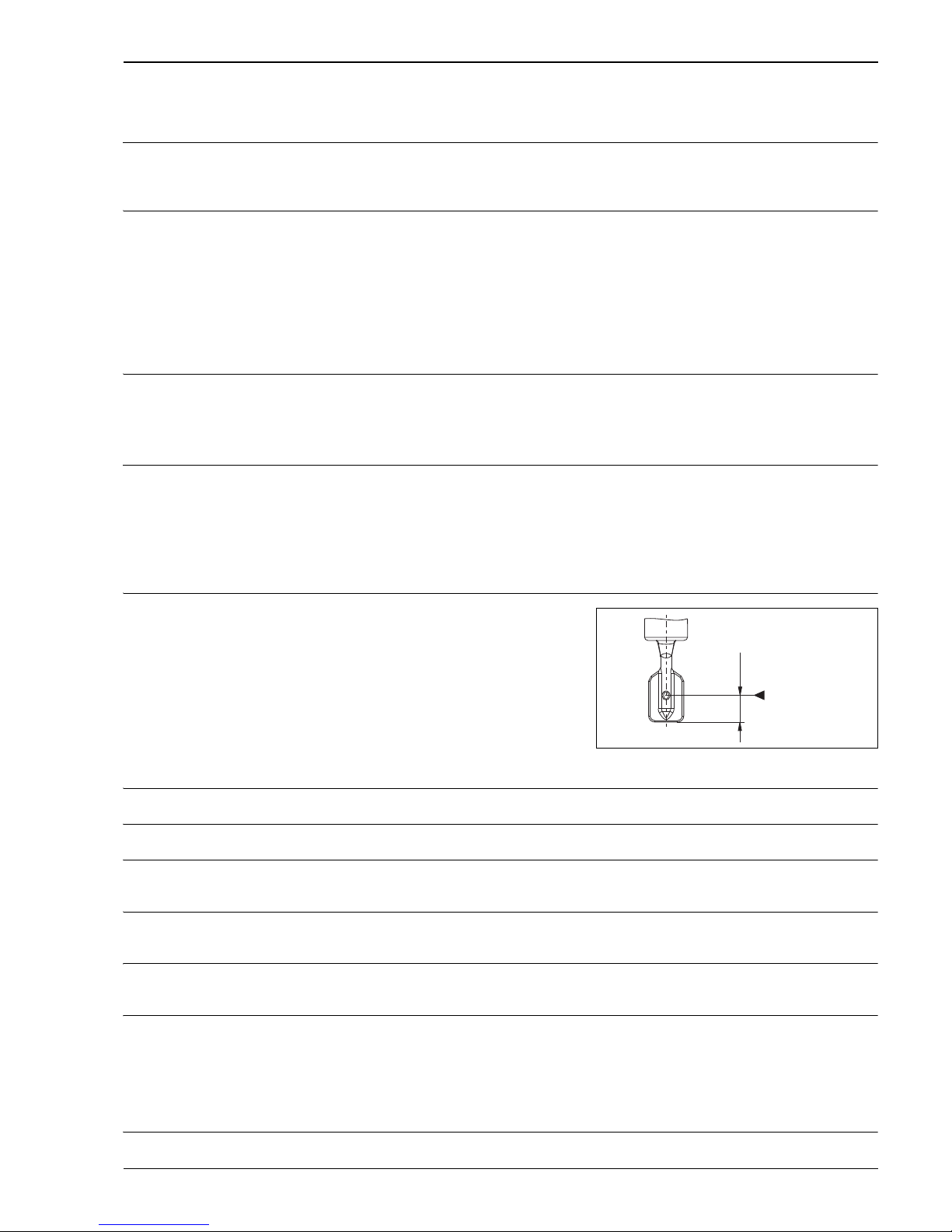
Maximum measured error Under reference operating conditions: max. +/–1 mm (0.04 in)
Repeatability 0.1 mm (0.004 in)
Hysteresis ECTFE and PFA: approx. 2 mm (0.08 in)
Enamel: approx. 2.5 mm (0.1 in)
Influence of medium
temperature
ECTFE and PFA: max. +1.4 mm to –2.8 mm (–50 to +120 °C / -58 to 248 °F)
Enamel: max. +0.6 mm to –1.5 mm (–50 to +150 °C / -58 to 302 °F)
Influence of medium density max. +4.8 mm to –3.5 mm ((0.5 to 1.5 g/cm
(SGU))
max. +0.19 in to -0.14 in
Influence of medium pressure ECTFE and PFA:
max. 0 mm to –2.0 mm (0 bar to 40 bar)
max. 0 in to -0.08 in (0 psi to 580 psi)
Enamel:
max. 0 mm to –1.0 mm (0 bar to 25 bar)
max. 0 in to -0.04 in (0 psi to 363 psi)
Switching delay • When fork is covered: 0.5 s
Ambient temperature: 23 °C (73 °F)
Medium temperature: 23 °C (73 °F)
Medium density (water): 1 g/cm
(SGU)
Medium viscosity: 1 mm/s (cSt)
Medium pressure p
e
: 0 bar (0 psi)
Sensor mounting: vertical from above
Density switch: to > 0.7 g/cm³ (SGU)
L00-FTL5xxxx-06-05-xx-xx-031
* Switch point under reference operating conditions
13
(0,51)
mm (in)
*
Page 20
Liquiphant M FTL51C
20 Endress+Hauser
• When fork is exposed: 1.0 s
• Available on request: 0.2 s; 1.5 s or 5 s (when the tuning fork is covered or exposed)
Operating conditions
Installation instructions
!
Note!
• The switch points of the LiquiphantM are at other positions to those of the previous version
LiquiphantII.
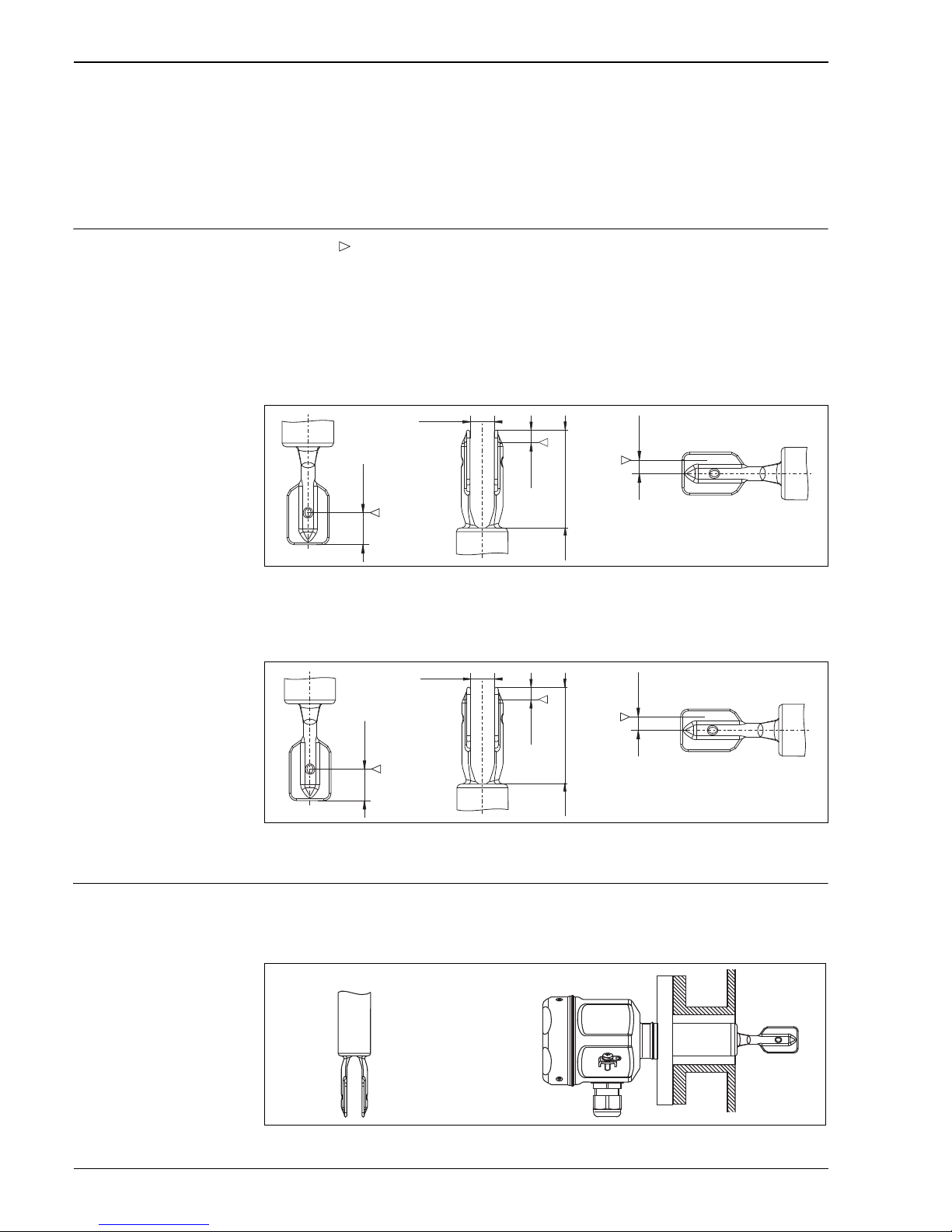
• Minimum distance between the tip of the fork and the tank wall or pipe wall: 10 mm
Synthetic coating:
L00-FTL5xxxx-06-05-xx-xx-051
Mounting from above Mounting from below Mounting from the side
Enamel coating:
L00-FTL5xxxx-06-05-xx-xx-051
Mounting from above Mounting from below Mounting from the side
Examples of mounting Examples of mounting with regard to the viscosity of the liquid and the tendency to form buildup
Optimum mounting, without problem even with high viscosity:
L00-FTL51Cxx-11-05-xx-xx-002
Vertical from above Flush-mounted from the side
Switch points on the sensor depend on the mounting position, with reference to water,
Density 1 g/cm
(SGU), 23 °C (73 °F), pe 0 bar (0 psi).
13
(0.51)
4
(0.16)
4
( 0.16)
mm (in)
10
(0. )39
40
(. )1 57
13
(0.51)
4
( 0.16)
mm (in)
10
(0. )39
46.5
(. )1 83
8
(0. 1)3
Page 21
Liquiphant M FTL51C
Endress+Hauser 21
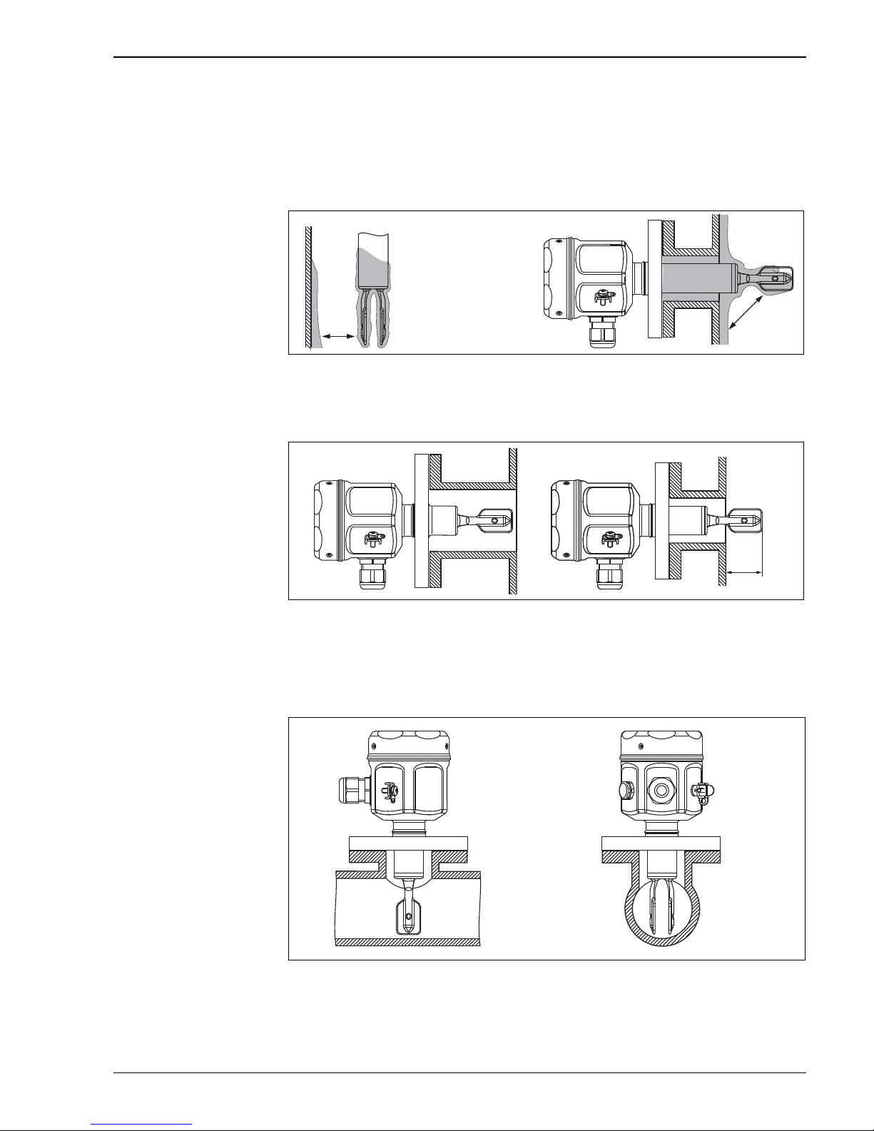
Position the fork so that the narrow edge of the tines is vertical to ensure that the liquid can run off
easily.
With buildup on the tank walls:
* Ensure that there is sufficient distance between the buildup expected on the tank wall
and the fork.
L00-FTL51Cxx-11-05-xx-xx-003
Vertical from above Protruding into the tank from the side
Mounting positions with low viscosity (up to 2000 mm/s):
L00-FTL51Cxx-11-05-xx-xx-004
* Deburr the nozzle surfaces
Mounting in piping from 2"
Flow velocities up to 5 m/s at a viscosity of 1 mm
/s (16.4 ft/s) and density of 1 g/cm. (Check function
for other medium conditions.)
L00-FTL51Cxx-11-05-xx-xx-005
*
*
(min. 1 in)
min. 25
DN 40
*
*
Page 22
Liquiphant M FTL51C
22 Endress+Hauser
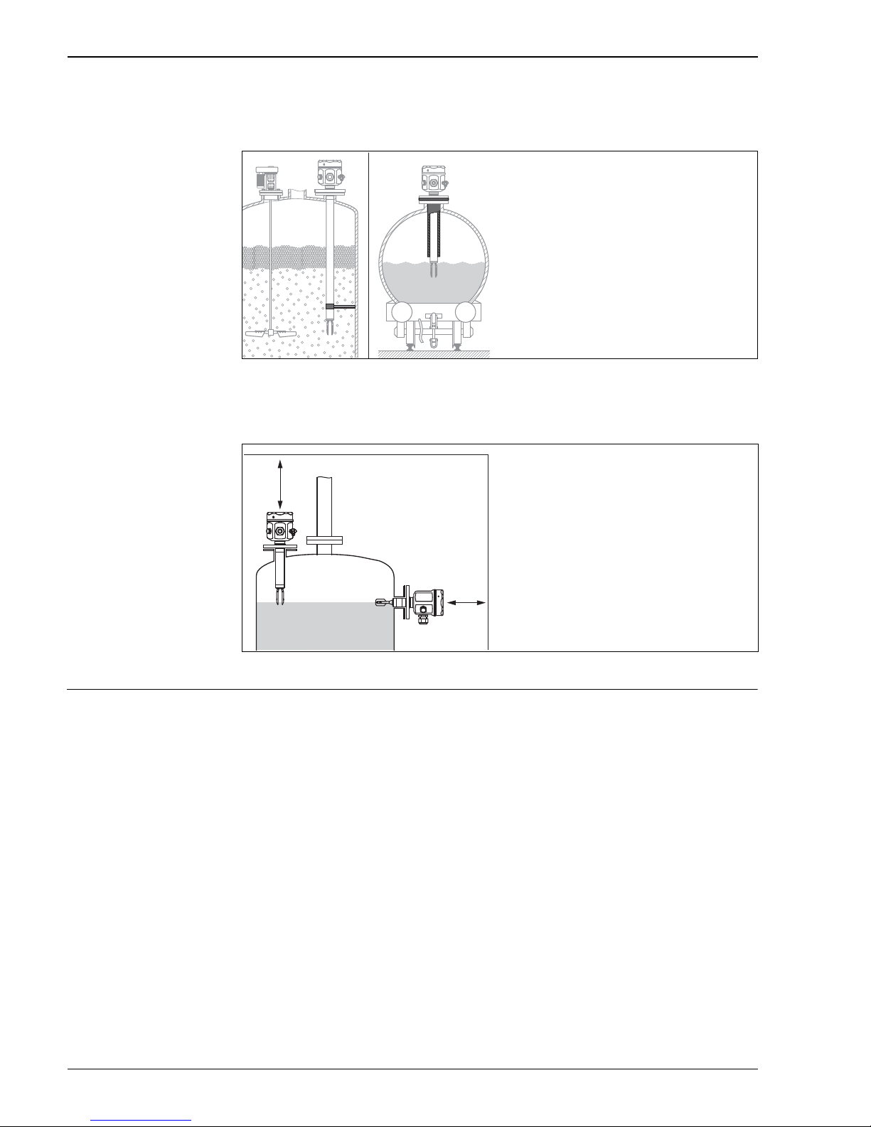
Support the device in the event of a severe dynamic load.
Support is possible only in conjunction with ECTFE or PFA synthetic coating.
L00-FTL5xxxx-11-05-xx-xx-005
Installation location
Ensure that there is adequate space outside the tank for mounting, connection and configuration.
L00-FTL51Cxx-11-05-xx-xx-006
Orientation FTL51C with short pipe up to approx. 500 (19.7 mm): any position
FTL51C with long pipe, vertical
.. .. .. .. .. .. .. .. .. .. .. .. .. .. .. .. .. .. .. .. .. .
.. .. .. .. .. .. .. .. .. .. .. .. .. .. .. .. ..
...........................................
.. .. .. .. .. .. .. .. .. .. .. .. .. .. .. .. .. ..
.. .. .. .. .. .. .. .. .. .. .. .. .. .. .. .. .. .. .. .. .. ..
.. .. .. .. .. .. .. .. .. .. .. .. .. .. .. .. .. .. .
...........................................
.. .. .. .. .. .. .. .. .. .. .. .. .. .. .. .. .. .
Page 23
Liquiphant M FTL51C
Endress+Hauser 23
Environment
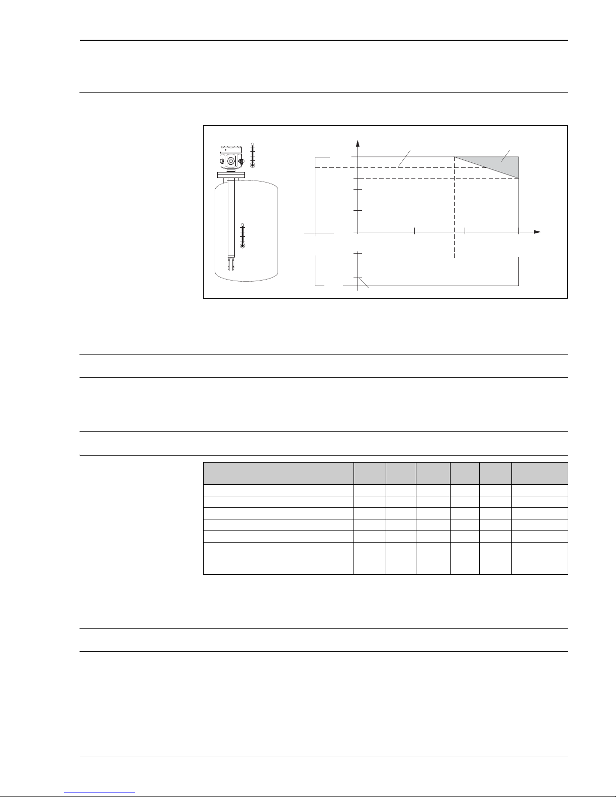
Ambient temperature range Permitted ambient temperature Ta at the housing depending on the medium temperature Tp in the
tank:
Storage temperature –50 to +80 °C (-58 to 176 °F)
Installation height as per
IEC61010-1 Ed.3
Up to 2000 m (6600 ft) above sea level.
Can be extended up to 3000 m (9800 ft) above sea level if overvoltage protection is used, for example
HAW562 or HAW569.
Climate class Climate protection to IEC 68, Part 2-38, Fig. 2a
Degree of protection
* As per EN60529
** As per NEMA 250
*** only with M20 cable entry or G1/2 thread
**** F13 housing only in conjunction with XP or Ex d approval
Vibration resistance As per IEC 68, parts 2-6 (10 to 55 Hz, 0.15 mm (0.01 in), 100 cycles)
Electromagnetic
compatibility
Interference emission to EN 61326, Electrical Equipment Class B
Interference immunity to EN 61326; Annex A (Industrial) and NAMUR Recommendation NE 21
(EMC)
L00-FTL5xxxx-05-05-xx-xx-001
*
**
***
Additional temperature range for devices with a temperature spacer or pressure tight feedthrough.
Maximum ambient temperature with FEL50D/FEL50A in hazardous areas.
For F16 housing, the following applies: -40 °C Ta +70 °C (-40 °F Ta +158 °F)
T
a
T
p
70
(158)
T
a
50
(122)
0
(32)
*
100
(212)
150
(302)
T
p
90
(194)
-50
(-58)
**
-50
(-58)
0
(32)
50
(122)
°C (°F)
***
-40
(-40)
Types of housing IP65 IP66* IP67* IP68* IP69 NEMA
type**
Polyester housing F16 – X X – – 4X
Stainless steel housing F15 – X X – – 4X
Aluminum housing F17 – X X – – 4X
Aluminum housing F13**** – X – X*** – 4X/6P
Stainless steel housing F27 – X – X – 4X/6P
Aluminum housing T13
with separate connection compartment
(Ex d)
–X– X***–4X/6P
Page 24

Liquiphant M FTL51C
24 Endress+Hauser
Medium conditions
Medium temperature ECTFE: –50 °C to +120 °C (–58 °F to +248 °F)
PFA: –50 °C to +150 °C (–58 °F to +302 °F) up to 230 °C (446 °F) special product on request
Enamel: max. –50 °C to +150 °C (–58 °F to +302 °F) up to 200 °C (392 °F) special product on request
Thermal shock 120 °C/s (248 °F/s)
Medium pressure p
e
The following values apply over the entire temperature range. Pay attention to exceptions for flange
process connections!
• ECTFE and PFA: –1 to +40 bar (–14.5 to 580 psi)
• Enamel: max. –1 to +25 bar (–14.5 to 363 psi)
Please refer to the standards listed for the permitted pressure values of the flanges at higher
temperatures:
• pR EN 1092-1: 2005
With regard to their stability-temperature property, the materials 1.4435 and 1.4404 are identical
and are grouped together
under 13E0 in EN 1092-1 Tab. 18. The chemical composition of the two materials can be identical.
• ASME B 16.5a - 1998 Tab. 2-2.2 F316
• ASME B 16.5a - 1998 Tab. 2.3.8 N10276
• JIS B 2220
The lowest value from the derating curves of the device and selected flange applies in each case.
Canadian CRN approval: Additional details on maximum pressure values are available in the download
area of the product page at "www.endress.com".
Test pressure p
e
= 100 bar (1450 psi):
•
150 bar (2175 psi) or 1.5 times the medium pressure p
e
)
• Sensor burst pressure at 200 bar (2900 psi)
!
Note!
Device function is not available during pressure testing.
Pressure shock 20 bar/s ( 290 psi)
State of aggregation Liquid
Density 0.7 g/cm
3
(SGU) = delivery status
0.5 g/cm3 (SGU) can be adjusted via switches
Viscosity 10,000 mm2/s (cSt)
Solids content
ø5 mm (0.2 in)
Lateral loading capacity 75 Nm
Page 25
Liquiphant M FTL51C
Endress+Hauser 25
Mechanical construction
!
Note!
2D and 3D drawings containing individual dimensions can be generated and downloaded in the
Configurator on the product pages of the Liquiphant FTL5x at www.endress.com.
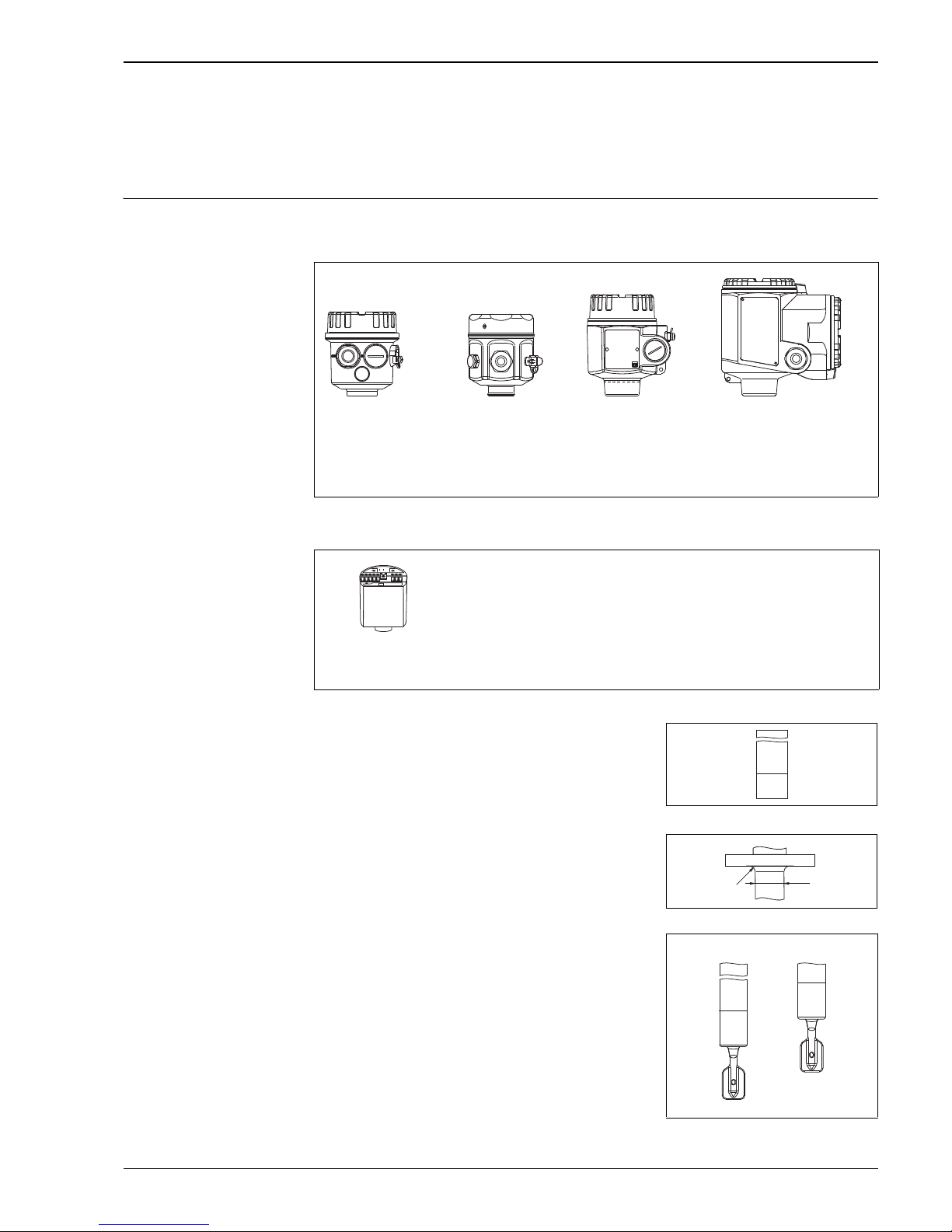
Design Summary of all electrical and mechanical versions
Housing
Plug-in electronic inserts to mount in the housing
L00-FTL5xxxx-03-05-xx-xx-001 L00-FTL5xxxx-03-05-xx-xx-002 L00-FTL5xxxx-03-05-xx-xx-003 L00-FTL5xxxx-03-05-xx-xx-004
F16
Polyester (PBT)
F15
Stainless steel
(316L)
F17/F13
Aluminum (also for
EEx d), coated
F27
Stainless steel (316L)
T13
Aluminum with separate
connection compartment (also
EEx de and EEx d), coated
L00-FTL5xxxx-03-05-xx-xx-000
FEL51:
FEL52:
FEL54:
FEL55:
FEL56:
FEL58:
FEL57:
FEL50A:
FEL50D:
Two-wire AC connection
Three-wire DC connection PNP
Universal current connection, 2 relay outputs
Output 16/8 mA for separate switching unit
Output 0.6 to 1.0 / 2.2 to 2.8 mA for separate switching unit (NAMUR)
Output 2.2 to 3.5 / 0.6 to 1.0 mA for separate switching unit (NAMUR)
Output 150/50 Hz, PFM, for separate switching unit (Nivotester)
Digital communication PROFIBUS PA
Pulse output for Density Computer FML621
Bushings
Temperature spacer and pressure tight feed-through
L00-FTL5xxxx-03-05-xx-xx-005
Process connections
Flanges* according to DIN/EN, ANSI, JIS from DN 40 / 1½"
* The following applies for DN 25/ANSI 1":
Pipe diameter (D)
24.2 mm, radius (R) 4 mm.
Take into account for counterflange!
L00-FTL5xxxx-03-05-xx-xx-009
Sensors
With extension pipe up to 3 m
or special "length L II" (see also Page 24)
Length L Length L II
L00-FTL51Cxx-03-05-xx-xx-001
D
R *
Page 26
Liquiphant M FTL51C
26 Endress+Hauser
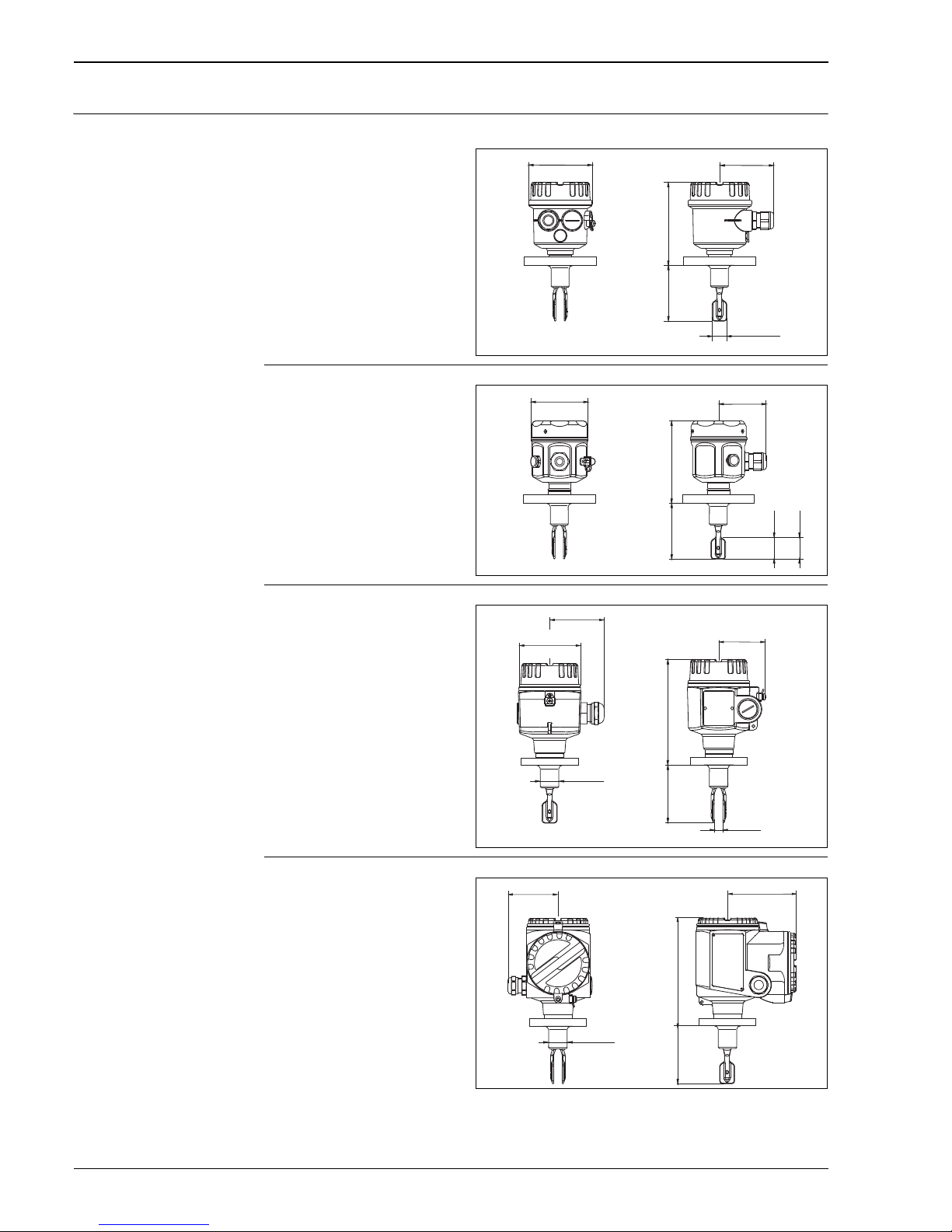
Dimensions (in mm) Housing and sensor FTL51C
Polyester housing F16
L00-FTL51Cxx-06-05-xx-xx-025
Stainless steel housing F15
L00-FTL51Cxx-06-05-xx-xx-126
Aluminum housing F17/F13
Stainless steel housing (316L) F27
L00-FTL5xxxx-06-05-xx-xx-006
Aluminum housing T13 with separate
connection compartment
L00-FTL5xxxx-06-05-xx-xx-007
* This length is customer-specific.
£
115 *
ø85
(3.35)
£76
(2.99)
£20.6
(0. )£ 81
£155
(6.1)
(£
4.53*)
~25 ECTFE, PFA
(0.98)
~29 Email/e
namel
(1.14)
ø76
(ø2.99)
£64
(2.52)
£150
(5.91)
£
115 *
(£
4.53*)
*
ø80
(3.15)
£69
(2.72)
£173
(6.81)
£60
(2.36)
10
(0.39)
ø21.5
(ø0.85)
*
£65
(2.56)
£97
(3.82)
£ 190
( 7.48)£
ø21.5
(ø0.85)
Page 27
Liquiphant M FTL51C
Endress+Hauser 27
!
Note!
The switch points of the Liquiphant M are at other positions to those of the previous version
Liquiphant II.
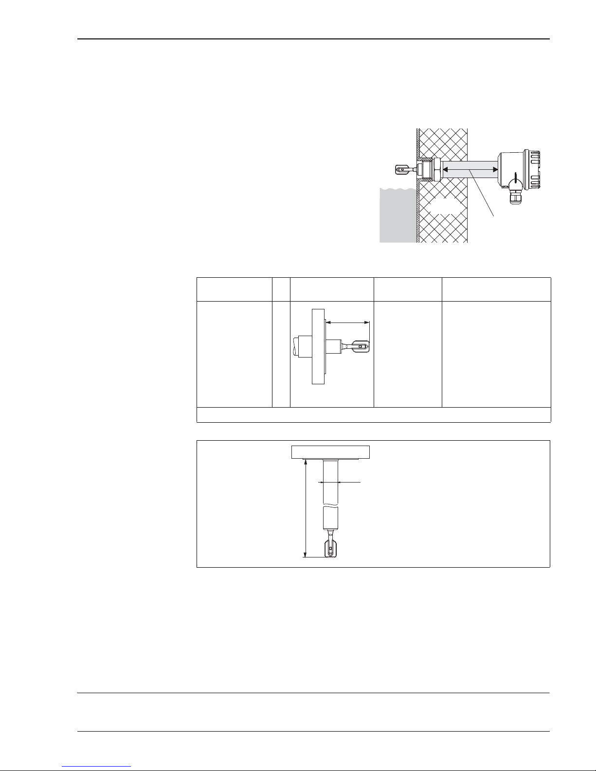
Bushings: temperature spacer, pressure tight feed-through
Process connections
Any length L:
148 mm to 3000 mm (6 in to 115 in) for synthetic coating
148 mm to 1200 mm (6 in to 48 in) for enamel coating
!
Note!
The switch points of the Liquiphant M are at other positions to those of the previous version
Liquiphant II.
Special length "L II": 115 mm (4.5 in)
If vertically mounted from above, the same switch point as for the Liquiphant II
FTL360, FTL365, FDL30, FDL35
Weights See Ordering information ä 33.
Temperature spacer
Provides sealed insulation for the vessel
and normal ambient temperatures
for the housing.
L00-FTL5xxxx-06-05-xx-xx-091
Pressure tight feed-through
Protects the housing from vessel pressures
up to 40 bar (580 psi)
if the sensor is damaged.
Provides sealed insulation for the vessel
and normal ambient temperatures
for the housing.
Process connection Dimensions Accessories Pressure
Temperature
Flanges:
Synthetic coating
ANSI B16.5 (RF)
EN 1092-1 (Form A)
JIS B 2220 (RF)
Enamel coating
ANSI B16.5 (RF)
EN 1092-1 (Form B)
JIS B 2220 (RF)
A#
#
B#
#
C##
K#
#
L00-FTL51Cxx-06-05-xx-xx-024
For synthetic
coating:
seal made of PTFE
supplied
In event of enamel
coating:
Se al p rov ide d by the
customer
See nominal pressure
of flange, however
For ECTFE:
For PFA
(Edlon*):
For enamel:
40 bar
120 °C
40 bar
150 °C
25 bar
150 °C
*) FDA-compliant material in accordance with 21 CFR Part 177.1550/2600
Sensor length L
for FTL51C
L00-FTL5xxxx-06-05-xx-xx-018
+ 140
(5.51)
Isolation
≥115
(≥4.53)
mm (in)
ø24,8
L
mm (in)
(0.98)
Page 28

Liquiphant M FTL51C
28 Endress+Hauser
Material Material specifications as per AISI and DIN-EN.
Parts in contact with process
• Extension pipe substrate Alloy C4 in the case of enamel coating: 316L (1.4435 oder 1.4404) in the
case of synthetic coating
• Fork substrate Alloy C4 in the case of enamel coating: 316L (1.4435) in the case of synthetic coating
•Flanges, coated:
Parts with no process contact
• Tuning fork/housing seal: EPDM
• Temperature spacer: 316 L (1.4435)
• Pressure-tight feedthrough: 316L (1.4435)
• Ground terminal on housing (external): 316L (1.4404)
• Cable glands
– Housing F13, F15, F16, F17: polyamide (PA)
In the case of approval B or C ( ä 33 Ordering information): nickel-plated brass
– Housing F27: polyamide PA, with approval "B" or "C" 316L (1.4435)
– Housing T13: nickel-plated brass
• Polyester housing F16: PBT-FR with PBT-FR cover or with PA12 transparent cover
– Cover seal: EPDM
– Nameplate glued: polyester film (PET)
– Pressure compensation filter: PBT-GF20
• Stainless steel housing F15: 316L (1.4404)
– Cover seal: silicone
– Safety claw: 304 (1.4301)
– Pressure compensation filter: PBT-GF20, PA
• Aluminum housing F17/F13: EN-AC-AlSi10Mg, plastic-coated
– Nameplate: aluminum, anodized
– Cover seal: EPDM
– Safety claw: nickel-plated brass
– Pressure compensation filter: silicone
• Stainless steel housing F27: 316L
– Nameplate: 316L (1.4404)
– Cover seal: FVMQ (optional: EPDM seal available as spare part)
– Safety claw: 316L (1.4435)
• Aluminum housing T13: EN-AC-AlSi10Mg, plastic-coated,
– Nameplate: aluminum, anodized
– Cover seal: EPDM
– Safety claw: nickel-plated brass
Process connections • Flanges made of 316L (1.4404) - synthetic coating; flanges made of 1.0487 (ASTMA 529) - enamel
coating
• Flanges as per EN/DIN 1092-1 from DN 25, as per ASME B16.5 from 1", as per JIS B 2220 (RF) from
10K50
Layer thickness ECTFE PFA*
(Edlon
TM
)
PFA
(RubyRed)
PFA
(conductive)
Enamel
Lower limit 0.5 mm 0.45 mm 0.45 mm 0.45 mm 0.4 mm
Upper limit 1.6 mm 1.6 mm 1.6 mm 1.6 mm 0.8 mm
Substrate 316L (1.4404) 316L (1.4404) 316L (1.4404) 316L (1.4404) 1.0487
* FDA-compliant in accordance with 21 CFR Part 177.1550
Page 29
Liquiphant M FTL51C
Endress+Hauser 29
Human interface
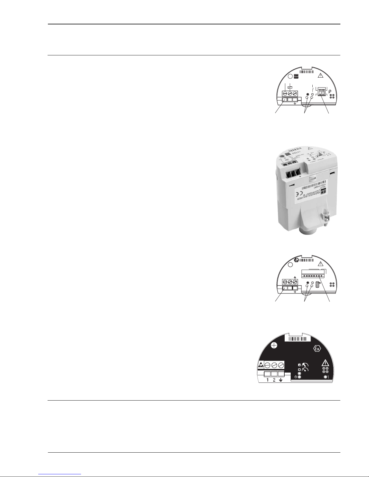
Electronic inserts
Operating concept Onsite configuration
With FEL51, FEL52, FEL54, FEL55:
• 2 switches for safety mode and density change
• green LED to indicate operational status
• red LED to indicate the switching status,
flashes in the event of corrosion damage on sensor
or if the electronics are defective
With FEL56:
• 2 switches for safety mode and density change
• green LED flashes to indicate operational status
• red LED to indicate the switching status,
flashes in the event of corrosion damage on sensor
or if the electronics are defective
With FEL57:
• 2 switches for density change and
Testing
• green LED to indicate operational status
• yellow LED to indicate the covered status,
flashes in the event of corrosion damage on sensor
or if the electronics are defective
With FEL58:
• 2 switches for safety mode and density change
•green LED
– flashes quickly to indicate operational status,
– flashes slowly in the event of corrosion damage to the
sensor of if the electronics are defective
• yellow LED to indicate the switching status,
Test key – breaks the cable connection
L00-FTL5xxxx-03-05-xx-en-001
L00-FTL5xxxx-03-05-xx-xx-013
With FEL50A:
• 8 switches for configuring the device address
• green LED to indicate operational status,
pulsing to indicate communication;
• yellow LED to indicate the switching status,
flashes in the event of corrosion damage on sensor
or if the electronics are defective
L00-FTL5xxxx-03-05-xx-en-002
With FEL50D:
• yellow LED: to indicate the validation of the
measurement
• green LED: to indicate the operational status
• red LED: to indicate faults
TI328Fxx004
Min
Max1
2
>0,7
>0,5
FEL51
12
L1 N
U~
19...253V AC
50/60Hz
I max : 350mA
Connecting terminal LEDs Switches
HW
OFF
ON
Address
SW
12345678
FEL50A
12
PA– PA+
Connecting terminal LEDs Switches
–
Impuls
FEL50D
+
GNYERD
Page 30

Liquiphant M FTL51C
30 Endress+Hauser
Certificates and approvals
Certificates See Ordering information ä 33.
CE mark The measuring system meets the legal requirements of the applicable EC Directives. These are listed in
the corresponding EC Declaration of Conformity along with the standards applied.
Endress+Hauser confirms successful testing of the device by affixing to it the CE mark.
RoHS The measuring system complies with the substance restrictions of the EU Directive on the restriction
of the use of certain hazardous substances 2011/65/EU (RoHS 2).
RCM-tick mark The product or measuring system supplied complies with the regulations of the Australian
Communications and Media Authority (ACMA) for network integrity, performance characteristics and
health and safety requirements. The specifications for electromagnetic compatibility, in particular, are
observed. The products bear the RCM-tick mark on their nameplate.
A0029561
EAC conformity The measuring system meets the legal requirements of the applicable EAC Directives. These
are listed in the corresponding EAC Declaration of Conformity along with
the standards applied.
Endress+Hauser confirms successful testing of the device by affixing to it the EAC mark.
CRN approval Versions with a CRN approval (Canadian Registration Number) are marked with a "*" in ordering
information feature 20 "process connection" (s. Seite 33 ff.). CRN-approved devices are assigned the
registration number CRN: 0F10904.5CADD1 on the nameplate. Further details are available in the
Downloads area on www.endress.com.
Pressure Equipment Directive
2014/68/EU (PED)
Pressure instruments with permitted pressure ≤ 200 bar (2 900 psi)
Pressure instruments with permitted pressure ≤ 200 bar (2 900 psi) Pressure instruments with a
flange and threaded boss that do not have a pressure-bearing housing do not fall within the scope of
the Pressure Equipment Directive, irrespective of the maximum permitted pressure.
Reason:
According to Article 2, point 5 of EU Directive 2014/68/EU, pressure accessories are defined as
"devices with an operational function and having pressure-bearing housings".
If a pressure instrument does not have a pressure-bearing housing (no identifiable pressure chamber
of its own), there is no pressure accessory present within the meaning of the Directive.
Process seal according to
ANSI/ISA 12.27.01
Practice in North America for the installation of process seals
Endress+Hauser devices are designed as either single seal or dual seal devices with an alarm in
accordance with ANSI/ISA 12.27.01. This means that the user does need to install for an external
secondary process seal in the thermowell which is required in ANSI/NFPA 70 (NEC) and CSA 22.1
(CEC). These devices comply with installation practice in North America and enable very safe, low-cost
installation in pressurized applications with hazardous media.
Further information on the specific device can be found in the following section: Safety Instructions
(ATEX) ä 38 ff.
Other certificates • Material certificate as per EN 10204/3.1 for all wetted parts NACE MR0175/MR0103, AD2000
• Leak detection system in conjunction with WHG approval
Approval number: Z–65.40–446 (see also "Ordering information" s. Seite 33 ff.)
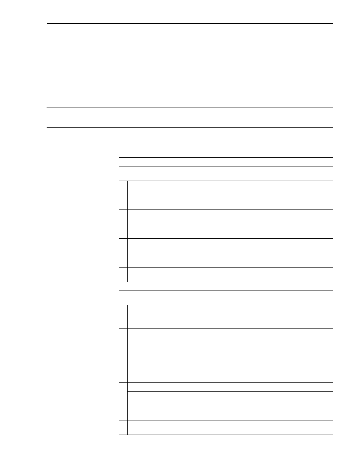
Product Type Max. process pressure Marking Listing
Liquiphant M FTL51-S/T##...
FTL51-P/Q/R##...
64/100 bar
(928/1450 psi)
Single Seal CSA
FM
Page 31
Liquiphant M FTL51C
Endress+Hauser 31
!
Note!
Device components in contact with the process are listed in the sections "Mechanical construction"
( ä 25 ff.) and "Ordering information" ( ä 33 ff.).
Manufacturer declarations The following documents can be ordered together with the document, depending on the desired device
configuration:
•FDA conformity
The applicable European guidelines and standards can be found in the relevant EU Declarations of
Conformity.
Use in hazardous zones Pay particular attention to the information provided in the documentation: Safety Instructions, Control
Drawings etc. ä 38
Combinations of coatings,
housings and electronic
inserts
Based on the various certificates, permissible combinations of coatings, housings *
and electronic inserts are given in the following table.
*) Abbreviations: Polyester = PBT, steel 1.4301/1.4435 = St., aluminum = Alu
Aluminum housing with separate connection compartment = Alu/sep.
Coating: ECTFE, PFA, enamel
Certificate,
applications
Housing Electronic inserts
A Without any special certificate
(for non-hazardous area)
PBT, St., Alu, Alu/sep. FEL51/52/54,
FEL55/56/57/58/50A/50D
D Overfill protection to WHG (Germany) PBT, St., Alu, Alu/sep. FEL51/52/54,
FEL55/56/57/58/50A
RFM, NI,
Cl. I, Div. 2, Gr. A–D
St., Alu, Alu/sep.
with NPT cable entry
FEL51/52/54,
FEL55/56/57/58/50D
PBT
with NPT cable entry
FEL51/52,
FEL55/56/57/58/50D
U CSA, General Purpose St., Alu, Alu/sep.
with NPT cable entry
FEL51/52/54,
FEL55/56/57/58/50D***
PBT
with NPT cable entry
FEL51/52,
FEL55/56/57/58/50D***
Y Other certificate
(for non-hazardous area)
PBT, St., Alu, Alu/sep. FEL51/52/54,
FEL55/56/57/58/50A/50D
Coating: enamel or PFA (conductive)
Certificate,
applications
Housing Electronic inserts
B ATEX II 3G EEx nC IIC T6, WHG PBT, St., Alu, Alu/sep. FEL54
ATEX II 3G EEx nC IIC T6, WHG
ATEX II 3D T85°C, WHG
St., Alu, Alu/sep. FEL54
C ATEX II 3G EEx nA IIC T6, WHG PBT, St., Alu, Alu/sep. FEL51/52/54,
FEL55/56/57/58/50A/
50D***
ATEX II 3G EEx nA IIC T6, WHG
ATEX II 3D T85°C, WHG
St., Alu, Alu/sep. FEL51/52/54,
FEL55/56/57/58/50A/
50D***
E ATEX II 1/2 G, EEx de IIC T6, WHG Alu/sep. FEL51/52/54,
FEL55/56/57/58/50A/50D
F ATEX II 1/2 G, EEx ia IIC T6, WHG PBT, St., Alu, Alu/sep. FEL55/56/57/58/50A/50D
ATEX II 1/2 G, EEx ia IIC T6, WHG
ATEX II 1/2 D, T80°C
St., Alu, Alu/sep. FEL51/52/54,
FEL55/56/57/58/50A/50D
L ATEX II 1/2 G, EEx d IIC T6, WHG Alu FEL51/52/54,
FEL55/56/57/58/50A/50D
P FM, IS, Cl. I, II, III, Div. 1, Gr. A–G PBT, St., Alu, Alu/sep.
with NPT cable entry
FEL55/56/57/58/50D/
50D***
Page 32

Liquiphant M FTL51C
32 Endress+Hauser
Q FM, XP, Cl. I, II, III, Div. 1, Gr. A–G Alu
with NPT cable entry
FEL51/52/54,
FEL55/56/57/58/50D
S CSA, IS, Cl. I, II, III, Div. 1, Gr. A–G PBT, St., Alu, Alu/sep.
with NPT cable entry
FEL55/56/57/58/50D/
50D***
T CSA, XP, Cl. I, II, III, Div. 1, Gr. A–G Alu
with NPT cable entry
FEL51/52/54,
FEL55/56/57/58/50D/
50D***
Coating: ECTFE, PFA (non-conductive)
Certificate,
applications
Housing Electronic inserts
1 ATEX II 1/2 G, EEx ia IIB T6, WHG PBT, St., Alu, Alu/sep. FEL55/56/57/58/50A/50D
2 ATEX II 1/2 G, EEx d IIB T6, WHG Alu FEL51/52/54,
FEL55/56/57/58/50A/50D
3 ATEX II 1/2 G, EEx de IIB T6, WHG Alu/sep. FEL51/52/54,
FEL55/56/57/58/50A/50D
4 ATEX II 1/2 G, EEx ia IIC** T6, WHG PBT, St., Alu, Alu/sep. FEL55/56/57/58/50A/50D
5 ATEX II 1/2 G, EEx d IIC** T6, WHG Alu FEL51/52/54,
FEL55/56/57/58/50A/50D
6 ATEX II 1/2 G, EEx de IIC** T6, WHG Alu/sep. FEL51/52/54,
FEL55/56/57/58/50A/50D
** With instruction: "Avoid electrostatic charge"
*** In preparation!
Page 33

Liquiphant M FTL51C
Endress+Hauser 33
Ordering information
Product structure Liquiphant
M FTL51C
Design Basic weight
FTL51C With extension pipe 0.6 kg
10 Approval:
A Non-hazardous area
B ATEX/NEPSI II 3 G EEx nC II T6 Overfill protection to WHG (Germany)
ATEX/NEPSI II 3 D T 85 °C*
C ATEX/NEPSI II 3 G EEx nA II T6 Overfill protection to WHG (Germany)
ATEX/NEPSI II 3 D T 85 °C*
D Non-hazardous area Overfill protection to WHG (Germany)
E ATEX II 1/2 G EEx de IIC T6 Overfill protection to WHG (Germany)
F ATEX II 1/2 G EEx ia IIC T6 Overfill protection to WHG (Germany)
ATEX II 1/2 D T 80 °C*
L ATEX II 1/2 G EEx d IIC T6 Overfill protection to WHG (Germany)
MNEPSI Ex ia IIC T6
N NEPSI Ex d IIC T6
P FM IS, Class I, II, III Division 1, Group A–G
Q FM XP, Class I, II, III Division 1, Group B–G, for E5 housing Group A–G
R FM NI, Class I Division 2, Group A–D
S CSA IS, Class I, II, III Division 1, Group A–G
T CSA XP, Class I, II, III Division 1, Group A–G
U CSA General Purpose
V TIIS Ex ia IIC T3
W TIIS Ex d IIB T3
X TIIS Ex ia IIC T6
Y Special version
1 ATEX II 1/2 G EEx ia IIB T6 Overfill protection to WHG (Germany)
2 ATEX II 1/2 G EEx d IIB T6 Overfill protection to WHG (Germany)
3 ATEX II 1/2 G EEx de IIB T6 Overfill protection to WHG (Germany)
4 ATEX II 1/2 G EEx ia IIC T6 Overfill protection to WHG (Germany)
Observe safety instructions (XA) (electrostatic charge)!
5 ATEX II 1/2 G EEx d IIC T6 Overfill protection to WHG (Germany)
Observe safety instructions (XA) (electrostatic charge)!
6 ATEX II 1/2 G EEx de IIC T6 Overfill protection to WHG (Germany)
Observe safety instructions (XA) (electrostatic charge)!
7 TIIS Ex d IIC T3
8 TIIS Ex d IIC T6
*) Not for PBT
20 Process connection: Additional weight
ACK* 1½" 150 lbs ECTFE > 316/316L Flange ANSI B16.5 1.5 kg
ACL* 1½" 150 lbs PFA (Edlon
TM
) > 316/316L Flange ANSI B16.5 1.5 kg
ACM* 1½" 150 lbs PFA (RubyRed) > 316/316L Flange ANSI B16.5 1.5 kg
ACN* 1½" 150 lbs PFA (conductive) > 316/316L Flange ANSI B16.5 1.5 kg
AEK* 2" 150 lbs ECTFE > 316/316L Flange ANSI B16.5 2.4 kg
AEL* 2" 150 lbs PFA (Edlon
TM
) > 316/316L Flange ANSI B16.5 2.4 kg
AEM* 2" 150 lbs PFA (RubyRed) > 316/316L Flange ANSI B16.5 2.4 kg
AEN* 2" 150 lbs PFA (conductive) > 316/316L Flange ANSI B16.5 2.4 kg
AES* 2" 150 lbs Enamel > 316/316L Flange ANSI B16.5 2.4 kg
AFK* 2" 300 lbs ECTFE > 316/316L Flange ANSI B16.5 3.2 kg
AFL* 2" 300 lbs PFA (Edlon
TM
) > 316/316L Flange ANSI B16.5 3.2 kg
AFM* 2" 300 lbs PFA (RubyRed) > 316/316L Flange ANSI B16.5 3.2 kg
AFN* 2" 300 lbs PFA (conductive) > 316/316L Flange ANSI B16.5 3.2 kg
AFS* 2" 300 lbs Enamel > 316/316L Flange ANSI B16.5 3.2 kg
ALK* 3" 150 lbs ECTFE > 316/316L Flange ANSI B16.5 4.9 kg
ALL* 3" 150 lbs PFA (Edlon
TM
) > 316/316L Flange ANSI B16.5 4.9 kg
ALM* 3" 150 lbs PFA (RubyRed) > 316/316L Flange ANSI B16.5 4.9 kg
ALN* 3" 150 lbs PFA (conductive) > 316/316L Flange ANSI B16.5 4.9 kg
APK* 4" 150 lbs ECTFE > 316/316L Flange ANSI B16.5 7.0 kg
APL* 4" 150 lbs PFA (Edlon
TM
) > 316/316L Flange ANSI B16.5 7.0 kg
APM* 4" 150 lbs PFA (RubyRed) > 316/316L Flange ANSI B16.5 7.0 kg
APN* 4" 150 lbs PFA (conductive) > 316/316L Flange ANSI B16.5 7.0 kg
A8K* 1" 150 lbs ECTFE > 316/316L Flange ANSI B16.5 1.0 kg
A8L* 1" 150 lbs PFA (Edlon
TM
) > 316/316L Flange ANSI B16.5 1.0 kg
A8M* 1" 150 lbs PFA (RubyRed) > 316/316L Flange ANSI B16.5 1.0 kg
Page 34

Liquiphant M FTL51C
34 Endress+Hauser
A8N* 1" 150 lbs PFA (conductive) > 316/316L Flange ANSI B16.5 1.0 kg
BBK DN32 PN25/40 ECTFE >316L Flange EN 1092-1 (DIN 2527) 2.0 kg
BBL DN32 PN25/40 PFA (Edlon
TM
) >316L Flange EN 1092-1 (DIN 2527) 2.0 kg
BBM DN32 PN25/40 PFA (RubyRed) >316L Flange EN 1092-1 (DIN 2527) 2.0 kg
BBN DN32 PN25/40 PFA (conductive) >316L Flange EN 1092-1 (DIN 2527) 2.0 kg
BDK DN40 PN25/40 ECTFE >316L Flange EN 1092-1 (DIN 2527) 2.4 kg
BDL DN40 PN25/40 PFA (Edlon
TM
) >316L Flange EN 1092-1 (DIN 2527) 2.4 kg
BDM DN40 PN25/40 PFA (RubyRed) >316L Flange EN 1092-1 (DIN 2527) 2.4 kg
BDN DN40 PN25/40 PFA (conductive) >316L Flange EN 1092-1 (DIN 2527) 2.4 kg
BEK DN50 PN6 ECTFE >316L Flange EN 1092-1 (DIN 2527) 1.6 kg
BEL DN50 PN6 PFA (Edlon
TM
) >316L Flange EN 1092-1 (DIN 2527) 1.6 kg
BEM DN50 PN6 PFA (RubyRed) >316L Flange EN 1092-1 (DIN 2527) 1.6 kg
BEN DN50 PN6 PFA (conductive) >316L Flange EN 1092-1 (DIN 2527) 1.6 kg
BGK DN50 PN25/40 ECTFE >316L Flange EN 1092-1 (DIN 2527) 3.2 kg
BGL DN50 PN25/40 PFA (Edlon
TM
) >316L Flange EN 1092-1 (DIN 2527) 3.2 kg
BGM DN50 PN25/40 PFA (RubyRed) >316L Flange EN 1092-1 (DIN 2527) 3.2 kg
BGN DN50 PN25/40 PFA (conductive) >316L Flange EN 1092-1 (DIN 2527) 3.2 kg
BNK DN80 PN25/40 ECTFE >316L Flange EN 1092-1 (DIN 2527) 5.9 kg
BNL DN80 PN25/40 PFA (Edlon
TM
) >316L Flange EN 1092-1 (DIN 2527) 5.9 kg
BNM DN80 PN25/40 PFA (RubyRed) >316L Flange EN 1092-1 (DIN 2527) 5.9 kg
BNN DN80 PN25/40 PFA (conductive) >316L Flange EN 1092-1 (DIN 2527) 5.9 kg
BQK DN100 PN10/16 ECTFE >316L Flange EN 1092-1 (DIN 2527) 5.6 kg
BQL DN100 PN10/16 PFA (Edlon
TM
) >316L Flange EN 1092-1 (DIN 2527) 5.6 kg
BQM DN100 PN10/16 PFA (RubyRed) >316L Flange EN 1092-1 (DIN 2527) 5.6 kg
BQN DN100 PN10/16 PFA (conductive) >316L Flange EN 1092-1 (DIN 2527) 5.6 kg
B8K DN25 PN25/40 ECTFE >316L Flange EN 1092-1 (DIN 2527) 1.4 kg
B8L DN25 PN25/40 PFA (Edlon
TM
) >316L Flange EN 1092-1 (DIN 2527) 1.4 kg
B8M DN25 PN25/40 PFA (RubyRed) >316L Flange EN 1092-1 (DIN 2527) 1.4 kg
B8N DN25 PN25/40 PFA (conductive) >316L Flange EN 1092-1 (DIN 2527) 1.4 kg
CGS DN50 PN25/40 Enamel >1.0487 Flange EN 1092-1 (DIN 2527) 3.2 kg
CNS DN80 PN25/40 Enamel >1.0487 Flange EN 1092-1 (DIN 2527) 5.9 kg
KEK 10 K 50 ECTFE >316L Flange JIS B2238 1.7 kg
KEL 10 K 50 PFA (Edlon
TM
) >316L Flange JIS B2238 1.7 kg
KEM 10 K 50 PFA (RubyRed) >316L Flange JIS B2238 1.7 kg
KEN 10 K 50 PFA (conductive) >316L Flange JIS B2238 1.7 kg
YY9* Special version
30 Probe length; Type:
BK ....... mm ECTFE 0.9 kg/m
BL ....... mm PFA (Edlon
TM
) 0.9 kg/m
BM ....... mm PFA (RubyRed) 0.9 kg/m
BN ....... mm PFA (conductive) 0.9 kg/m
BS ....... mm Enamel 0.9 kg/m
CK ....... inch ECTFE 2.3 kg/100 in
CL ....... inch PFA (Edlon
TM
) 2.3 kg/100 in
CM ....... inch PFA (RubyRed) 2.3 kg/100 in
CN ....... inch PFA (conductive) 2.3 kg/100 in
CS ....... inch Enamel 2.3 kg/100 in
DK Length: type II** ECTFE
DL Length: type II** PFA (Edlon
TM
)
DM Length: type II** PFA (RubyRed)
DN Length: type II** PFA (conductive)
DS Length: type II** Enamel
YY Special version
**) If replacing devices: When vertically mounting a Liquiphant M FTL51C
with length II, the switch point is at the same level as for a Liquiphant II
FTL360, FTL365, FDL30, FDL35
40 Electronics; output:
A FEL50A PROFIBUS PA
D FEL50D Density/concentration
1 FEL51 2-wire 19 to 253 V AC
2 FEL52 3-wire PNP 10 to 55 V DC
4 FEL54 Relay DPDT 19 to 253 V AC, 19 to 55 V DC
5 FEL55 8/16 mA, 11 to 36 V DC
6 FEL56 NAMUR (L-H signal)
7 FEL57 2-wire PFM
20 Process connection: Additional weight
Page 35
Liquiphant M FTL51C
Endress+Hauser 35
8 FEL58 NAMUR + test keys (H-L signal)
9 Special version
50 Housing; cable entry:
E1* F27 316L NEMA6P; Thread NPT ¾
E4 F16 Polyester NEMA4X; Thread NPT ½
E5 F13/F17 Alu NEMA4X; Thread NPT ¾ 0.5 kg
E6 F15 316L NEMA4X; Thread NPT ½ 0.1 kg
E7 T13 Alu coated, IP66; Thread NPT ¾ 0.9 kg
Separate connection compartment
F1* F27 316L IP68 Thread G1/2
F4 F16 Polyester IP66; Thread G ½
F5 F13/F17 Alu IP66; Thread G ½ 0.5 kg
F6 F15 316L IP66; Thread G ½ 0.1 kg
F7 T13 Alu coated, IP66; Thread G ½ 0.9 kg
Separate connection compartment
G1* F27 316L IP68; M20 threaded joint
G4 F16 Polyester IP66; M20 threaded joint
G5 F13/F17 Alu IP66; M20 threaded joint 0.5 kg
(EEx d > M20 thread)
G6 F15 316L IP66; M20 threaded joint 0.1 kg
G7 T13 Alu coated, IP66; M20 threaded joint 0.9 kg
Separate connection compartment (EEx d > M20 thread)
N4 F16 Polyester IP66; M12 connector
N5 F13/F17 Alu IP66; M12 connector
N6 F15 316L IP66; M12 connector
Y9 Special version
* F27 housing in preparation.
60 Additional options 1:
A Not selected
K Special adjustment, density H20
L Special adjustment, density H20, EN10204-3.1
S GL/ABS marine approval (
1600 mm)
Y Special version
70 Additional options 2:
ANot selected
B Temperature spacer
C 2nd line of defence > pressure tight feed-through
Y Special version
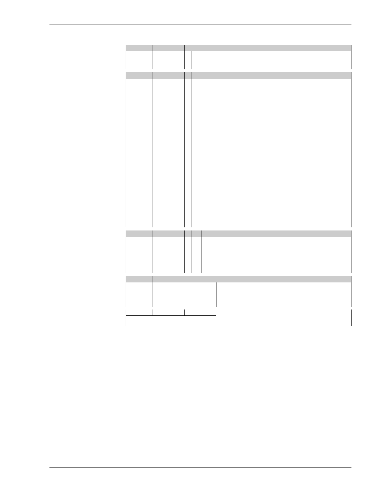
FTL51C - Complete product designation
Note!
The basic weight includes the compact sensor, electronic insert and polyester housing
40 Electronics; output:
Page 36
Liquiphant M FTL51C
36 Endress+Hauser
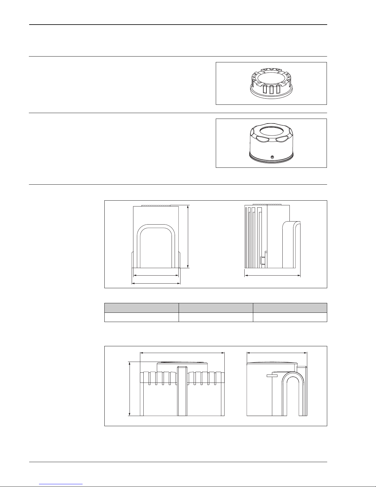
Accessories
Transparent cover
Cover with sight glass
Weather protection cover For F16 housing
A0018225
For F13, F17 and F27 housing
A0018226
For polyester housing F16
Material: PA 12
Weight: 0.04 kg
Order number: 943461-0001
L00-FTL5xxxx-03-05-xx-xx-016
For stainless steel housing F15
Material: AISI 316L
Weight: 0.16 kg
– With glass sight glass
Order number: 943301-1000
– With PC sight glass
Order number: 52001403
(Not for CSA, General Purpose)
L00-FTL5xxxx-03-05-xx-xx-017
Material Order No. Weight
PBT, gray 71127760 240 g (8.46 oz)
ø110 (4.33)
114 (4.49)
140 (5.51)
140 (5.51)
mm (in)
102 (4.02)
162 (6.38)
mm (in)
112 (4.41)
Page 37

Liquiphant M FTL51C
Endress+Hauser 37
Documentation
!
Note!
You can find supplementary documentation on the product pages at www.endress.com
Operating Instructions Electronic insert FEL50A for Liquiphant M/S PROFIBUS PA
BA00141F/00/en
Liquiphant M density, density computer FML621
BA00335F/00/en
Liquiphant MFTL51C
KA00162F/00/a6
Liquiphant M FTL51C-######## 7 ##
KA00165F/00/a6
Liquiphant M density FTL50, FTL51
Electronic insert: FEL50D
KA00284F/00/a6
Liquiphant M density FTL50H, FTL51H
Electronic insert: FEL50D
KA00285F/00/a6
Liquiphant M density FTL51C
Electronic insert: FEL50D
KA00286F/00/a6
Technical Information General instructions for electromagnetic compatibility
(Test procedure, installation recommendation)
TI00241F/00/en
Liquiphant M FTL50/51(H), for process temperatures up to 150 °C
TI00328F/00/en
Isolating amplifier FTL325P,
1 or 3-channel switching units for top-hat rail mounting
for Liquiphant M/S with electronic insert FEL57
TI350F/00/en
Isolating amplifier FTL325N,
1 or 3-channel switching units for top-hat rail mounting
for Liquiphant M/S with electronic insert FEL56, FEL58
TI353F/00/en
Liquiphant S FTL70/71, for medium temperatures up to 280 °C
TI354F/00/en
Isolating amplifier FTL375P,
1 to 3-channel switching units for top-hat rail mounting
for Liquiphant M/S with electronic insert FEL57
TI360F/00/en
Liquiphant M density, density computer FML621
TI420F/00/en
Weld-in adapter,
TI00426F
Functional safety (SIL) Liquiphant M with electronic insert FEL51 (MAX)
SD00164F
Material Order No. Weight
PA6, gray 71040497 300 g (10.58 oz)
Page 38

Liquiphant M FTL51C
38 Endress+Hauser
Liquiphant M with electronic insert FEL51 (MIN)
SD00185F
Liquiphant M with electronic insert FEL52 (MAX)
SD00163F
Liquiphant M with electronic insert FEL52 (MIN)
SD00186F
Liquiphant M with electronic insert FEL54 (MAX)
SD00162F
Liquiphant M with electronic insert FEL54 (MIN)
SD00187F
Liquiphant M with electronic insert FEL55 (MAX)
SD00167F
Liquiphant M with electronic insert FEL55 (MIN)
SD00279F
Liquiphant M with electronic insert FEL57 + Nivotester FTL325P
SD01508F (MAX + MIN)
Liquiphant M with electronic insert FEL56 + Nivotester FTL325N
SD01521F (MAX + MIN)
Liquiphant M with electronic insert FEL58 + Nivotester FTL325N
SD01522F (MAX + MIN)
Safety Instructions (ATEX) 40II 1/2 G, Ex d IIC/B (KEMA 99 ATEX 1157)
XA00031F/00/a3
40II 1/2 G, Ex ia/ib IIC/B (KEMA 99 ATEX 0523)
XA00063F/00/a3
40II 1 G, Ex ia IIC/B (KEMA 99 ATEX 5172 X)
XA00064F/00/a3
40II 1/2 G, Ex de IIC/B (KEMA 00 ATEX 2035)
XA00108F/00/a3
40II 3 G, Ex nA/nC II (EG 01 007-a)
XA00182F/00/a3
Safety Instructions (NEPSI) Ex d IIC/IIB T3-T6 , Ex d IIC T2-T6
(NEPSI GYJ06424)
XA00401F/00/B2
Ex ia IIC T2-T6, Ex ia IIB T3-T6
(NEPSI GYJ05556, NEPSI GYJ06464),
XC00009F/00/b2
Ex nA II T3-T6, Ex nC/nL IIC T3-T6
(NEPSI GYJ04360, NEPSI GYJ071414)
XC00010F/00/b2
Control Drawings Liquiphant M (IS and NI) Current output PFM, NAMUR Entity installation
Class I, Div. 1, 2, Groups A, B, C, D
Class I, Zone 0
Class II, Div. 1, 2, Groups E, F, G
Class III
ZD00041F
Liquiphant M, Liquiphant S (cCSAus / IS)
Class I, Div. 1, Groups A, B, C, D Ex ia IIC T6
Class II, Div. 1, Groups E, F, G
Class III
ZD00042F
Page 39

Liquiphant M FTL51C
Endress+Hauser 39
Liquiphant M (NI), FTL50(H), FTL51(H), FTL51C, FTL70, FTL71
Class I, Div. 2, Groups A, B, C, D
Class II, Div. 2, Groups F, G
Class III
ZD00043F
Liquiphant M, Liquiphant S (cCSAus / XP)
Class I, Groups A, B, C, D
Class II, Groups E, F, G
Class III
ZD00240F
Liquiphant M (IS and NI) PROFIBUS PA, FOUNDATION FieldbusClass I, Zone 0, IIC
Class I, Division 1, 2, Groups A, B, C, D
Class II, Division 1, 2, Groups E, F, G
Class III
ZD00244F
Page 40

www.addresses.endress.com
7131030371310310
 Loading...