

Page 1
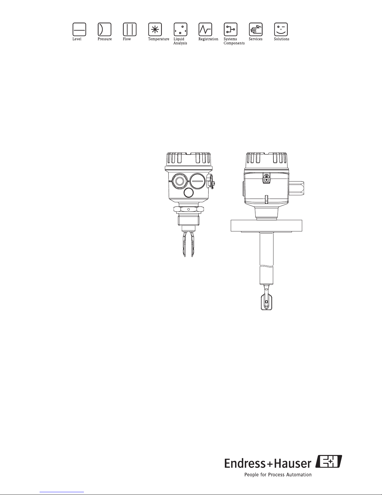
Operating Instructions
Liquiphant M FTL50, FTL51
Level Limit Switch
BA213F/24/ae/03.06
52005008
Page 2

Operating Instructions Liquiphant M FTL50 / FTL51
Table of Contents
Safety Instructions
Order Codes
Installation
Setup
Maintenance & Cleaning
Technical Data
Troubleshooting
Spare Parts
Supplemental documentation
2 Endress+Hauser
Page 3
Liquiphant M FTL50 / FTL51 Operating Instructions
1 Safety Instructions
Safe and secure operation of the unit can only be guaranteed if the operating instructions and all
safety notes are read, understood and followed.
1.1 Approved usage
The Liquiphant M FTL50 and FTL51 is designed for level limit detection in liquids. If used incorrectly, it is possible that application-related dangers may arise. The level limit switch Liquiphant M
FTL50 and 51 may be installed, connected, commissioned, operated and maintained by qualified
and authorized personnel only, under strict observance of these operating instructions, any relevant
standards, legal requirements, and, where appropriate, the certificate.
1.2 Safety pictograms and symbols
Safe and reliable operation of this unit can only be guaranteed if the safety hints and warnings in
these operating instructions are followed. The safety hints in these instructions are highlighted using
the following symbols:
"
!
0-
.
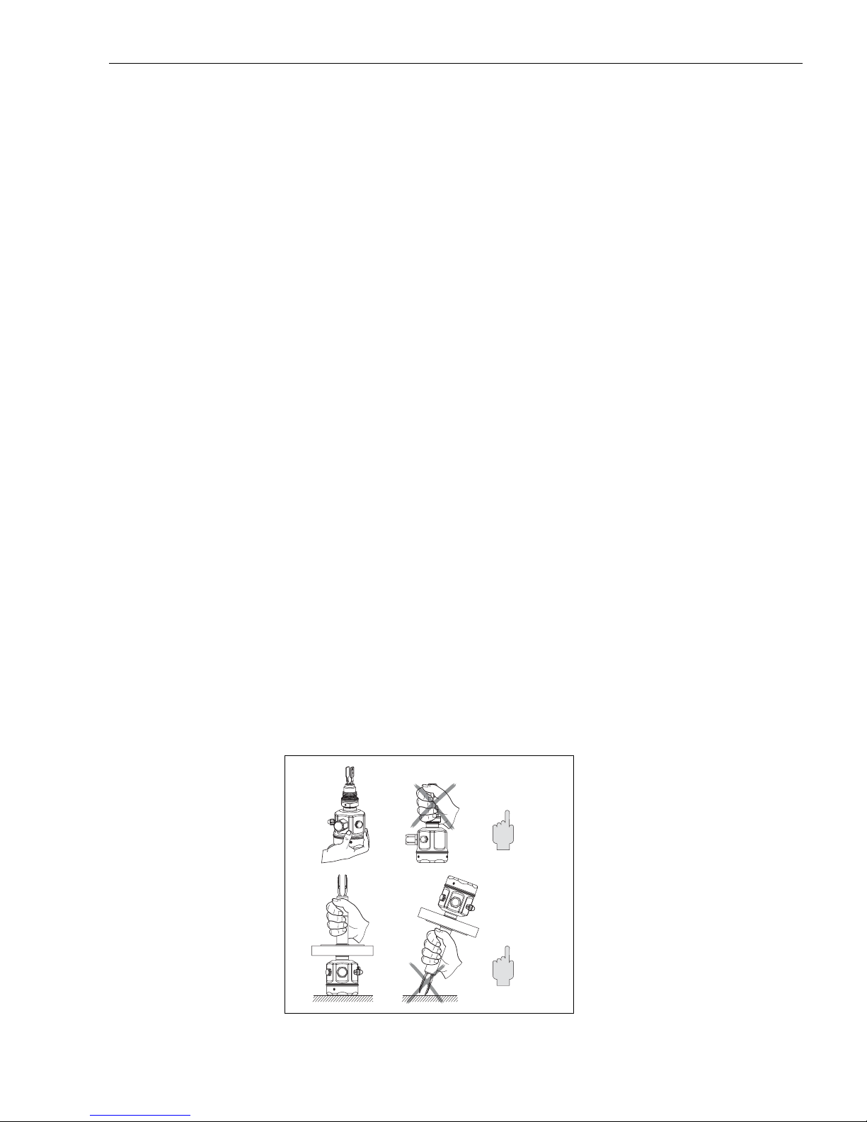
Hold by housing, flange or
extension tube
Caution!
This symbol indicates activities and actions that, if followed incorrectly, could lead to faulty operation or even damage to the unit.
Note!
This symbol indicates activities and actions that, if followed incorrectly, could have an indirect influence on the unit operation or could lead to an unforeseen unit reaction.
Hazardous area, certified equipment!
If this character is shown on the unit, then it may be operated in hazardous areas.
Non-hazardous area!
This symbol identifies the non-hazardous areas in these instructions. Units that operate in the nonhazardous areas but that are connected to the hazardous areas must also be certified.
1.3 Handling
Endress+Hauser 3
kA143Y02ae.eps
Page 4
Operating Instructions Liquiphant M FTL50 / FTL51
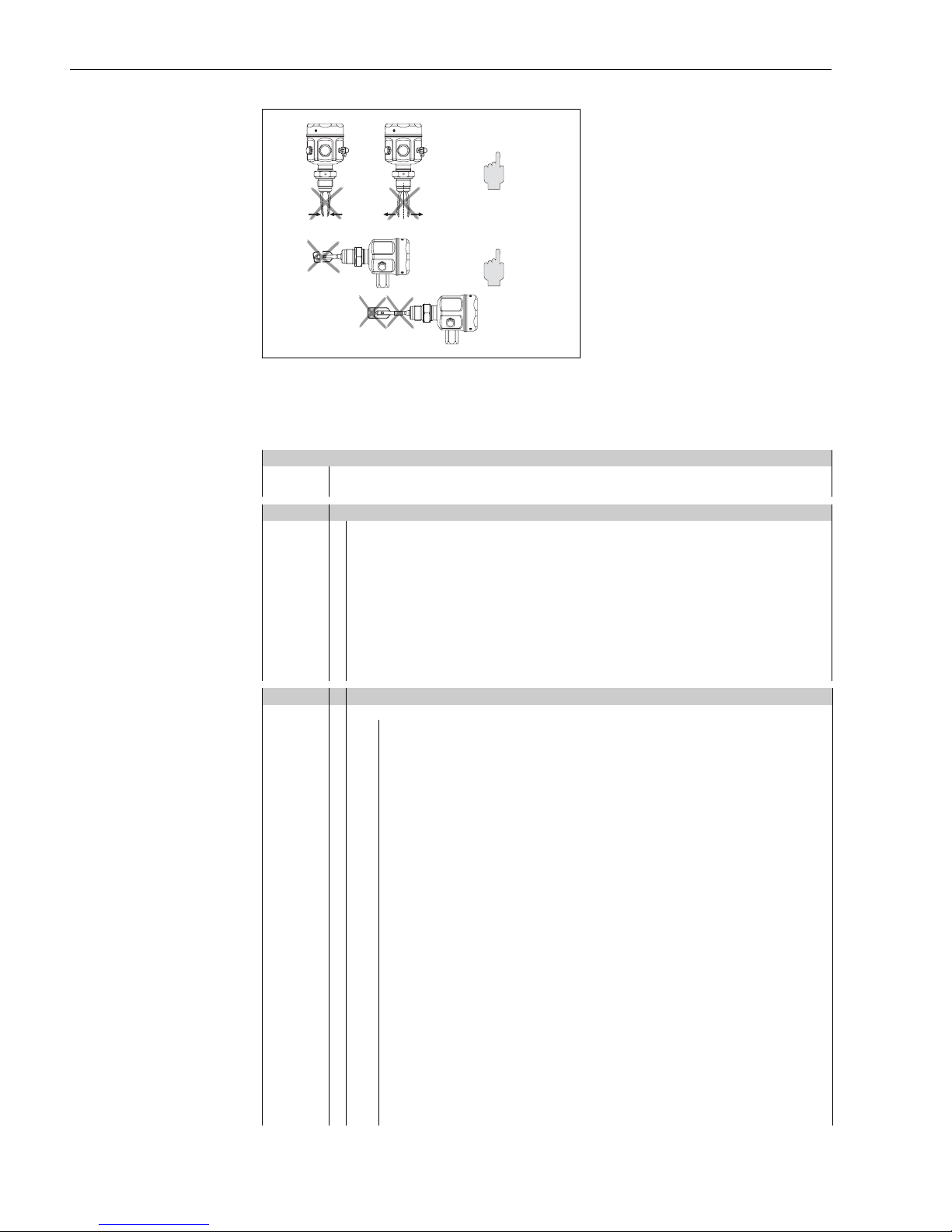
Do not bend.
Do not shorten.
Do not lengthen
KA143Y03ae.eps
2 Order Codes
Product structure
Design Basic weight
FTL50 Compact 1.3 lb 0.6 kg
FTL51 With extension pipe 1.3 lb 0.6 kg
10 Certificates, applications
A Version for non-hazardous area
P FM IS, Class I, II, III Division 1, Group A-G
Q FM XP, Class I, II, III Division 1, Group B-G, for E5 housing Group A-G
R FM NI, Class I Division 2, Group A-D
S CSA IS, Class I, II, III Division 1, Group A-G
T CSA XP, Class I, II, III Division 1, Group A-G
U CSA General Purpose
YSpecial version
ATEX and TIIS certified units available
on request
20 Process connection, material Additional weight
Note: For 1450 psi (100 bar) process pressure, please select the appropriate option under "Additional option"
Installation in welding neck accessory
GM2 ¾" NPT Thread ANSI 316L
GM5 ¾" NPT Thread ANSI Alloy C4
GN2 1" NPT Thread ANSI 316L 0.4 lb 0.2 kg
GN5 1" NPT Thread ANSI Alloy C4 0.4 lb 0.2 kg
A82 1" 150 lb RF Flange ANSI B16.5 316/316L 2.2 lb 1.0 kg
AA2 1-¼" 150 lb RF Flange ANSI B16.5 316/316L 2.6 lb 1.2 kg
AB2 1-¼" 300 lb RF Flange ANSI B16.5 316/316L (FTL 51) 4.4 lb 2.0 kg
AC2 1-½" 150 lb RF Flange ANSI B16.5 316/316L 3.3 lb 1.5 kg
AD2 1-½" 300 lb RF Flange ANSI B16.5 316/316L (FTL 51) 6.0 lb 2.7 kg
AE2 2" 150 lb RF Flange ANSI B16.5 316/316L 5.3 lb 2.4 kg
AE5 2" 150 lb RF Flange ANSI B16.5 Alloy C4 >316/316L 5.3 lb 2.4 kg
AF2 2" 300 lb RF Flange ANSI B16.5 316/316L 7.1 lb 3.2 kg
AG2 2" 600 lb RF Flange ANSI B16.5 316/316L (FTL 51) 9.3 lb 4.2 kg
AJ2 2-½" 300 lb RF Flange ANSI B16.5 316/316L (FTL 51) 10.6 lb 4.8 kg
AL2 3" 150 lb RF Flange ANSI B16.5 316/316L 10.8 lb 4.9 kg
AM2 3" 300 lb RF Flange ANSI B16.5 316/316L (FTL 51) 15 lb 6.8 kg
AN2 3" 600 lb RF Flange ANSI B16.5 316/316L (FTL 51)
AP2 4" 150 lb RF Flange ANSI B16.5 316/316L 15.4 lb 7.0 kg
AQ2 4" 300 lb RF Flange ANSI B16.5 316/316L (FTL 51) 25.4 lb 11.5 kg
AR2 4" 600 lb RF Flange ANSI B16.5 316/316L (FTL 51) 38.1 lb 17.3 kg
TC2 DN 25-38 (1 to 1-½") ISO 2852 Tri-Clamp 316L 0.2 lb 0.1 kg
TE2 DN 40-51 (2") ISO 2852 Tri-Clamp 316L 0.7 lb 0.3 kg
YY9 Special version
4 Endress+Hauser
Other process connections available, contact Endress+Hauser
Page 5
Liquiphant M FTL50 / FTL51 Operating Instructions
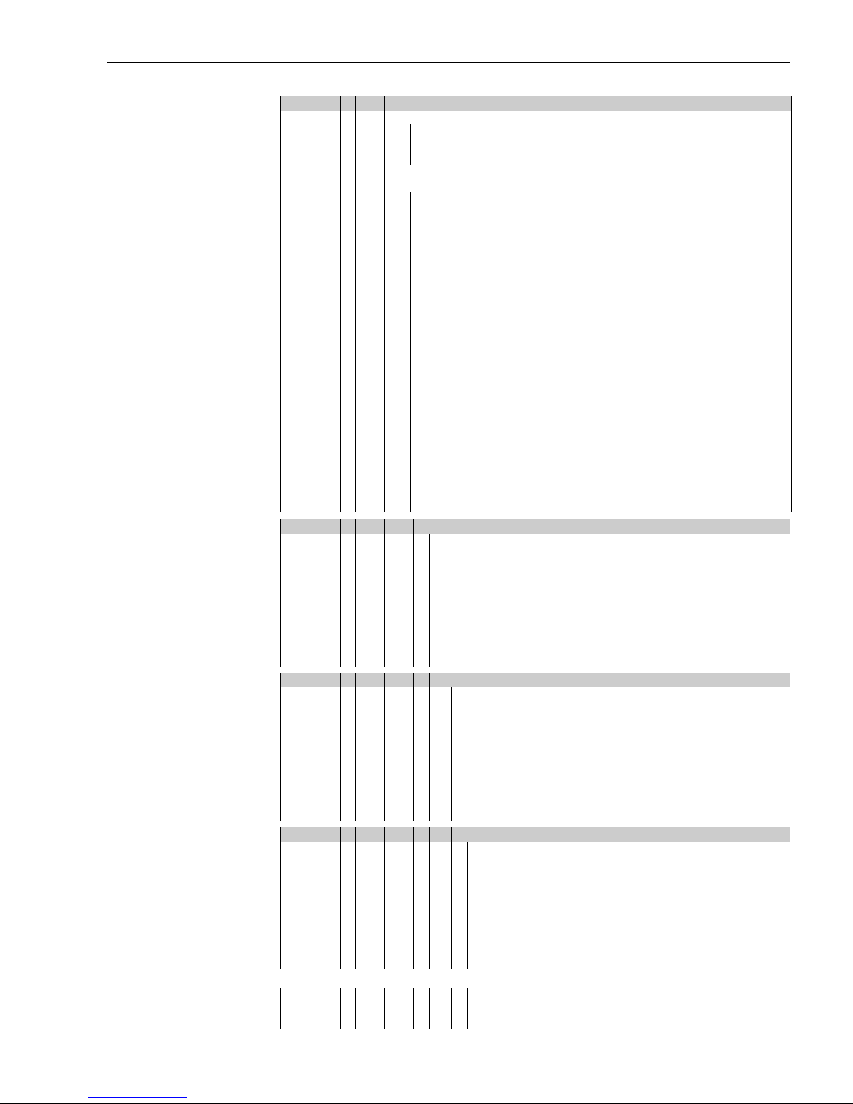
30 Length, spacer, pressure tight bushing
FTL50
AA Compact Ra <3.2 µm/80 grit
IA 66 mm / 2.6" + temperature spacer 1.3 lb 0.6 kg
QA 66 mm / 2.6" + pressure tight bushing 1.5 lb 0.7 kg
FTL51
CB ....... in (6 in to 115 in) Ra 3.2 µm 316L**
CE ....... in (6 in to 115 in) Ra 3.2 µm Alloy C4** 5 lb (2.3 kg)/100 in
DB Length II* Ra 3.2 µm 316L 0.2 lb 0.1 kg
DE Length II* Ra 3.2 µm Alloy C4 0.2 lb 0.1 kg
KB ....... in (6 in to 115 in)
+ temperature spacer
KE ....... in (6 in to 115 in)
+ temperature spacer
LB Length II*
+ temperature spacer
LE Length II*
+ temperature spacer
SB ....... in (6 in to 115 in)
+ pressure tight bushing
SE ....... in (6 in to 115 in)
+ pressure tight bushing
TB Length II*
+ pressure tight bushing
TE Length II*
+ pressure tight bushing
YY Special version
316L** 5 lb (2.3 kg)/100 in
316L** 5 lb (2.3 kg)/100 in
316L 0.2 lb
Alloy C4 0.2 lb
316L** 5 lb (2.3 kg)/100 in
Alloy C4** 5 bl (2.3 kg)/100 in
316L 0.2 lb
Alloy C4 0.2 lb
+1.3 lb (+0.6 kg)
+1.3 lb (+0.6 kg)
+1.3 lb
+1.3 lb
+1.5 lb +0.7 kg
+1.5 lb +0.7 kg
+1.5 lb
+1.5 lb
0.1 kg
+0.6 kg
0.1 kg
+0.6 kg
0.1 kg
+0.7 kg
0.1 kg
+0.7 kg
*) Replacing instruments: when vertically mounting a Liquiphant M
FTL51 with length II, the switch point is at the same height as for the
Liquiphant II FTL360, FTL365, FDL30, FDL35
**) order 3001 to 6000 mm (116 to 235 in) via yy
40 Electronic insert
1 FEL51* Contact-free two-wire, 19 to 253 V AC
2 FEL52* PNP three-wire, 10 to 55 V DC
4 FEL54 Floating change-over contacts, DPDT, 19 to 253 V AC, 19 to 55 V DC
5 FEL55 8/16 mA, 11 to 36 V DC
6FEL56 NAMUR
7 FEL57 Two-wire PFM
8 FEL58* NAMUR with push button (disconnects wire)
9 Special version
*) Also available in compact housing
50 Housing, cable entry
C3 Compact housing 316L IP66/68 5m cable
D3 Compact housing 316L IP65 Pg11 connector
E3 Compact housing 316L NEMA4x NPT1/2" connector
N3 Compact housing 316L IP66/68 M12 connector
E4 Polyester housing Nema 4x, NPT ½"
E5 Aluminum housing Nema 4x,NPT ¾" 1.1 lb/0.5 kg
E6 316L housing Nema 4x, NPT ½" 0.2 lb/0.1 kg
E7 Aluminum housing IP66 NPT ¾",
with separate connection compartment
Y9 Special version
60 Additional fittings
A No additional fittings
C 3.1.B material, wetted parts 316L,
Inspection certificate to EN 10204, in accordance with Specification 52005759
N NACE 3.1.B
P 1450 psi (100 bar) process pressure (FTL51)
R 1450 psi (100 bar) process pressure, EN 10204 - 3.1 material, NACE
MR0175 (316L wetted parts) (FTL51)
Inspection certificate
S GL marine approval (FTL 51: max. length 63"/1600 mm)
Y Special version
2.0 lb/0.9 kg
FTL 5# - Complete product designation
Endress+Hauser 5
Page 6
Operating Instructions Liquiphant M FTL50 / FTL51
3 Installation
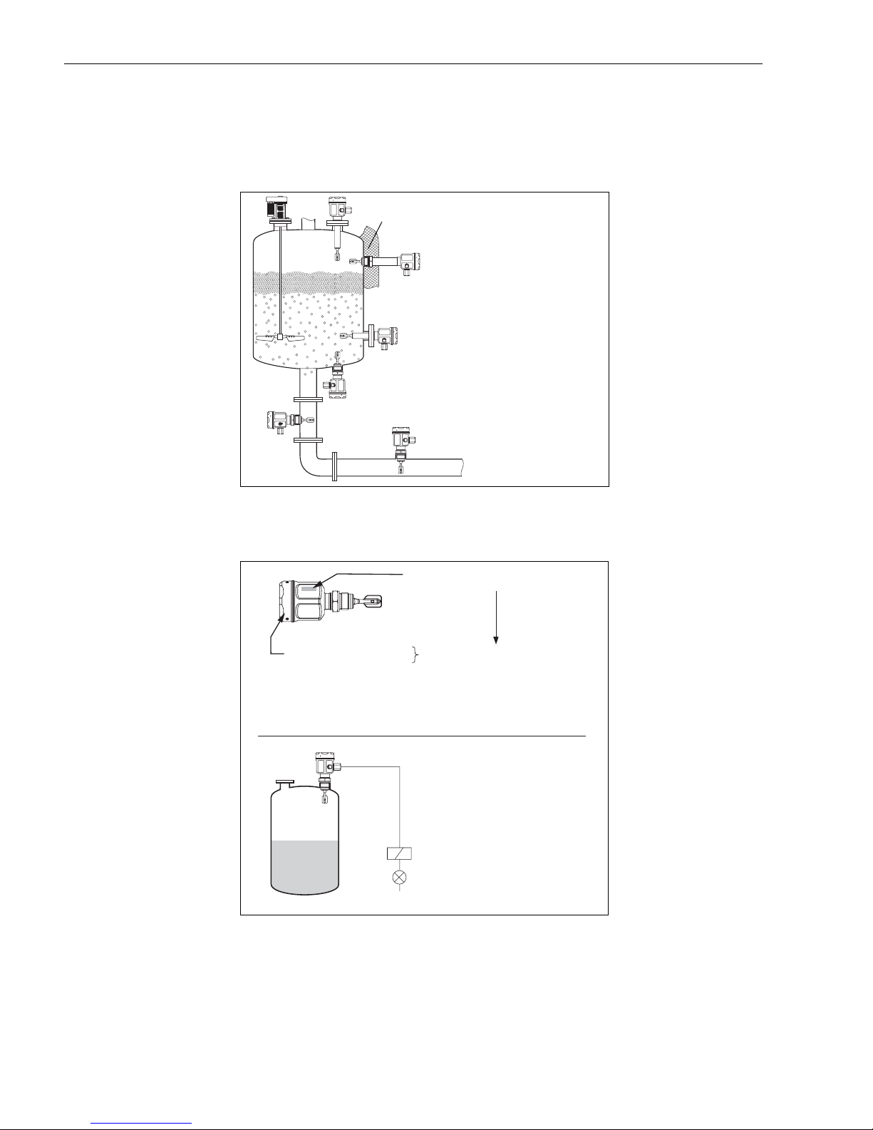
3.1 Application
Level limit detection in
liquids
"T"
For direct connection
3.2 Measuring System
Order code:
FTL5#-###### ####
Electronic inserts
External load
FEL 5
FEL 5
FEL 5
KA143Y10ae.eps
1
2
4
6 Endress+Hauser
…
KA143Y11ae.eps
Page 7
Liquiphant M FTL50 / FTL51 Operating Instructions
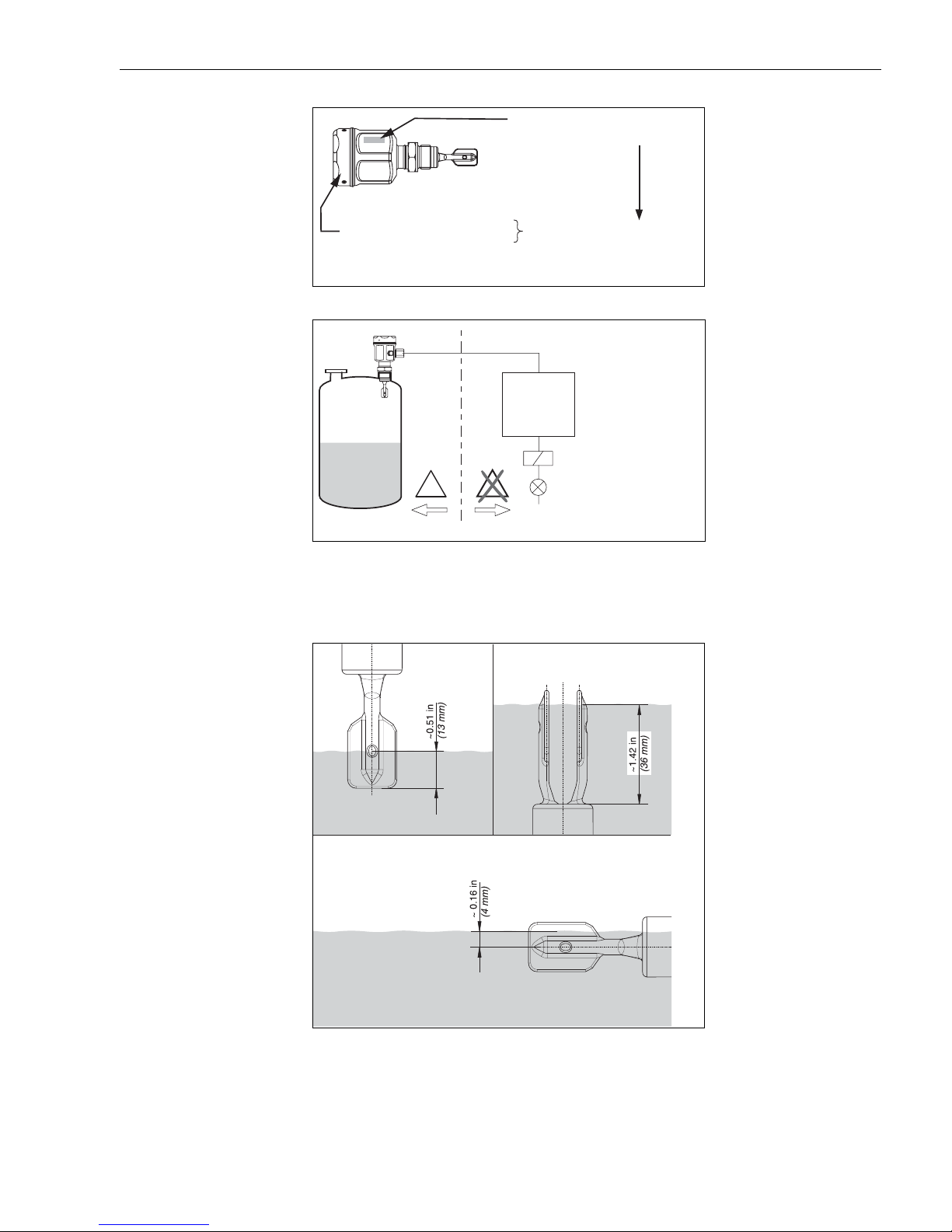
For connection via
switching unit
Electronic insert
E
Order code:
FTL5#-###### ####
5
FEL 5
6
FEL 5
7
FEL 5
8
FEL 5
I.S.
*)
FTL…,
SIF…, SIN…,
FXN…
X
E
X
*) Switching unit, PLC,
isolating amplifier
KA143Y12ae.eps
…
KA143Y13ae.eps
Switchpoint depends on
mounting position
!
3.3 Installation
KA143Y15ae.eps
Note!
The switchpoints of the Liquiphant M are at different positions than those of the previous version
Liquiphant II.
Endress+Hauser 7
Page 8
Operating Instructions Liquiphant M FTL50 / FTL51
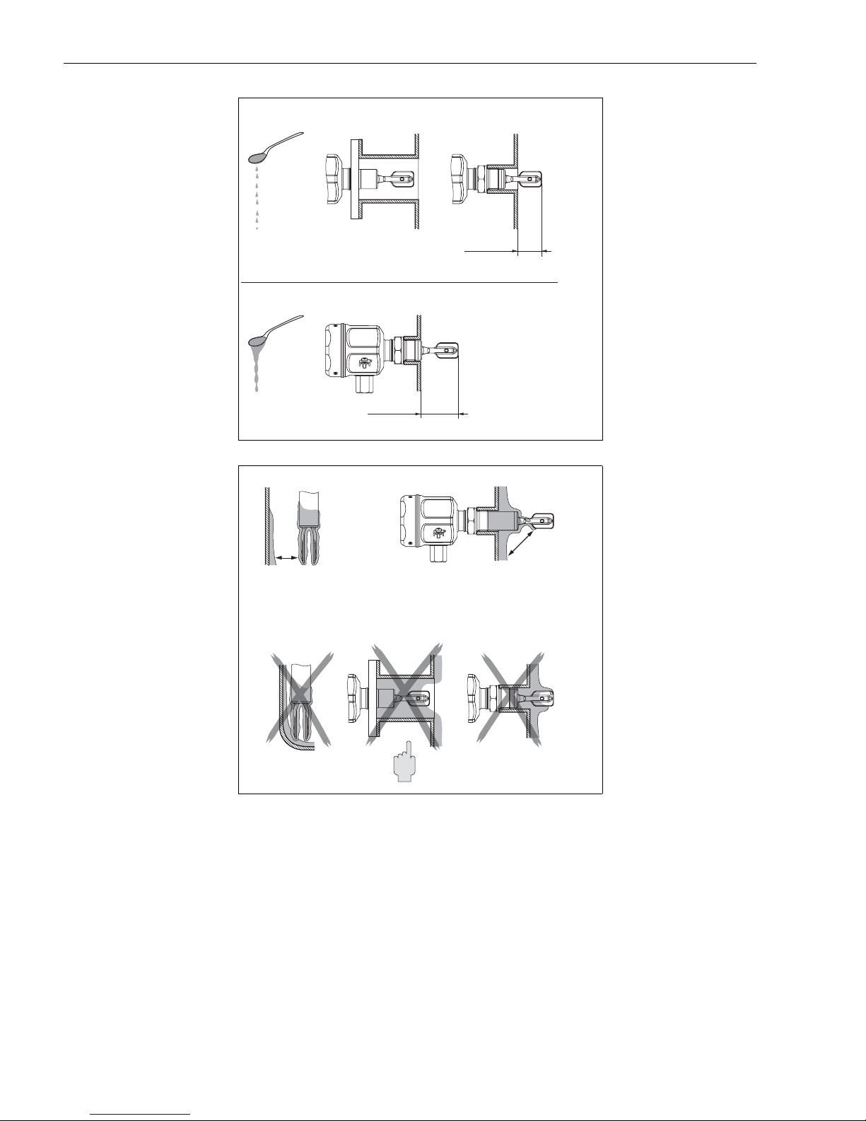
Mounting examples as a
function of liquid viscosity
Consider buildup.
Fork may not contact the
buildup
n = 0 - 2000 cP
n = 0 - 10,000 cP
min. 2"
(min. DN 50)
*Deburr
min. 1.5 in
(min. 40 mm)
*
min. 1 in
min. 25 mm()
*
KA143Y16ae.eps
*
*Distance
*
KA143Y17ae.eps
8 Endress+Hauser
Page 9
Liquiphant M FTL50 / FTL51 Operating Instructions
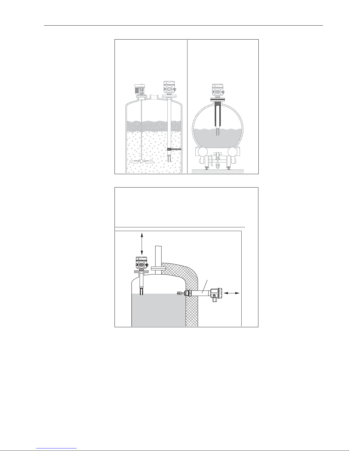
In cases of dynamic forces
support
KA143Y18ae.eps
Allow clearance
"T" = with temperature spacer for insulated tanks
.. .. .. .. .. .. .. .. .. .. .. .. .. .. .. .. .. .. .. .. .. .. .. .. .. ..
.. .. .. .. .. .. .. .. .. .. .. .. .. .. .. .. .. .. .. .. .. .. .. .. .. ..
.. .. .. .. .. .. .. .. .. .. .. .. .. .. .. .. .. .. .. .. .. .. .. .. .. ..
.. .. .. .. .. .. .. .. .. .. .. .. .. .. .. .. .. .. .. .. .. .. .. .. .. .
"T"
.. .. .. .. .. .. .. .. .. .. .. .. .. .. .. .. .. .. ..
KA143Y19ae.eps
.. .. .. .. .. .. .. .. .. .. .. .. .. .. .. .. .. .. ..
.. .. .. .. .. .. .. .. .. .. .. .. .. .. .. .. .. .. ..
.. .. .. .. .. .. .. .. .. .. .. .. .. .. .. .. .. .. ..
Endress+Hauser 9
Page 10
Operating Instructions Liquiphant M FTL50 / FTL51
41
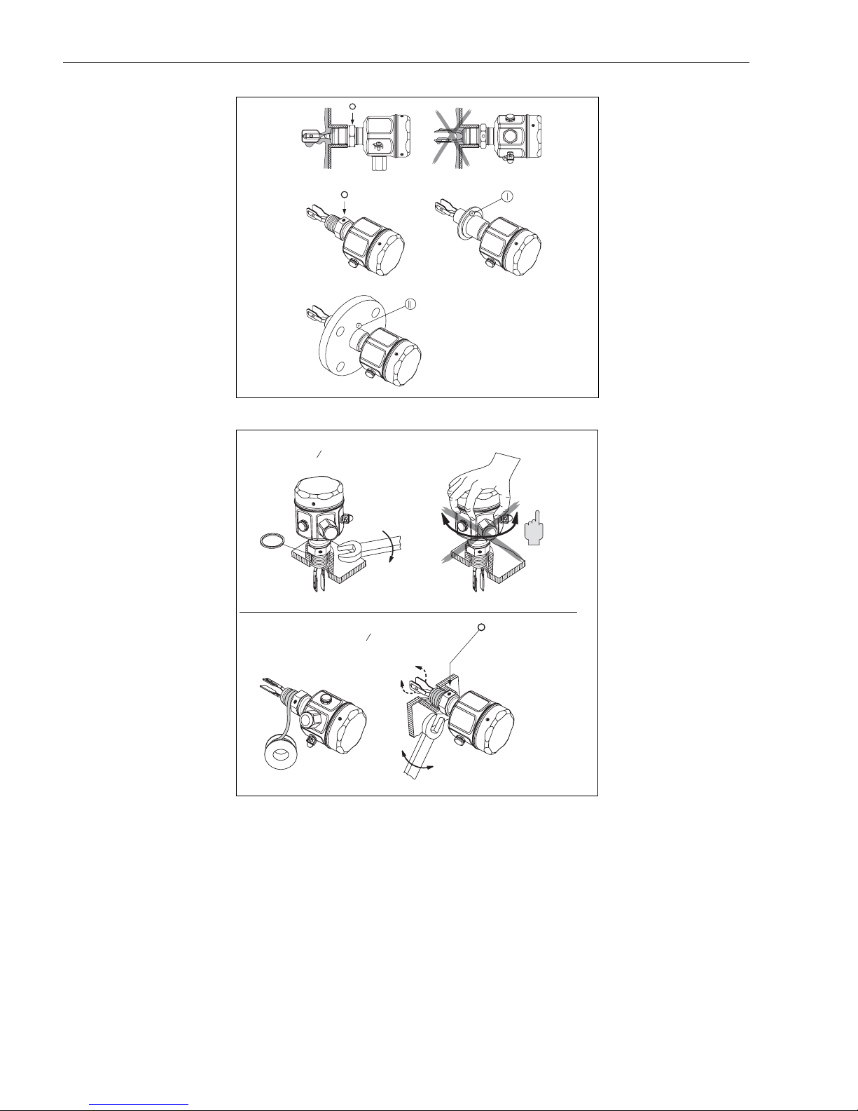
Orientation of fork tines:
marking above or below
KA143Y20ae.eps, KA143Y21ae.eps
Screw Liquiphant into
process connection.
DON’T use housing to turn.
G ¾ A, SW ( )
G 1 A, SW ( )
¾ NPT, R ¾, G ¾ A, SW ( )
1 NPT, R 1, G 1 A, SW ( )
1¼" 32 mm
5
1 " 41 mm
8
41
1¼" 32 mm
5
1 " 41 mm
8
F
E
T
P
T
E
N
F
O
L
A
Above or below
!
41
B
KA143Y22ae.eps
10 Endress+Hauser
Page 11
Liquiphant M FTL50 / FTL51 Operating Instructions
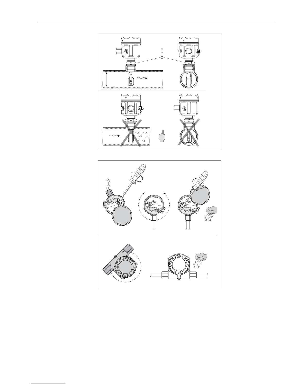
Orientation in pipes:
marking in direction of
flow
Ø
min. 2"
(ø )
min. 50 mm
Max. 16 ft/s
5 m/s(max. )
KA143Y23ae.eps
Cable entry orientation
F15
3to4
turns
1. 2. 3.
1
2
12
... 270°
F16, F13, F17
... 300°
0.9 Nm
12
*Torque
*
KA143Y24ae.eps
Endress+Hauser 11
Page 12
Operating Instructions Liquiphant M FTL50 / FTL51
4Setup
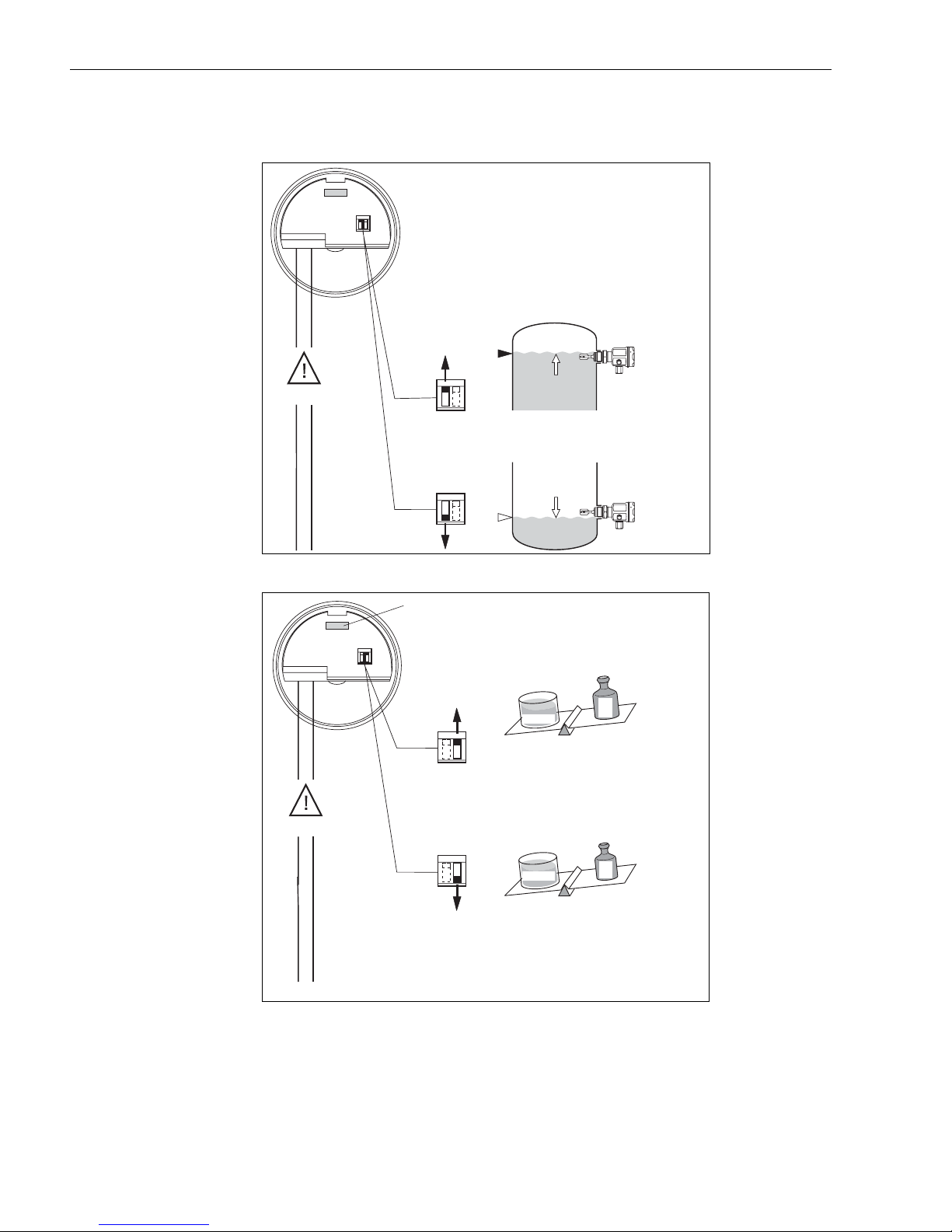
Minimum/maximum failsafe mode
Max.
Max.
0V
Liquid density.
Density ρ measured in
3
g/cm
(SGU) or in kg/l
0V
Min.
FEL , FEL , FEL , FEL , FEL , FEL , FEL51 52 54 55 56 57 58
> 0.7 ( 5.9 lbs.)r
Standard
Min.
r
5.9
1US gal
1 US. gal = min. 5.9 lbs
(1 l (1 dm³) = min 0.7 kg)
(1 imp.gal = min. 7.0 lbs)
lbs
r
4.2
lbs
> 0.5
( 4.2 - 5.9 lbs.)r
e.g. Propane
1US gal
1 US. gal = 4.2 - 5.9 lbs
(1 imp.gal = 5.0 - 0.7 lbs)
1l(1dm³) = 0.5 - 0.7 kg
()
KA143Y25ae.eps
12 Endress+Hauser
KA143Y26ae.eps
Page 13
Liquiphant M FTL50 / FTL51 Operating Instructions
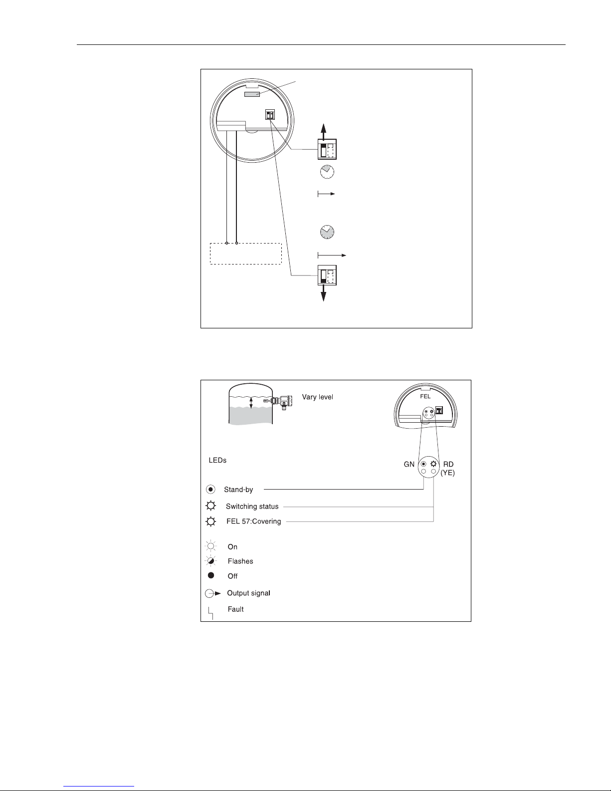
Self test FEL57 (See page 21 and
FEL 57
switching unit for
sequence)
Standard
With corrosion test
KA143Y27ae.eps
+–
Switching unit
STD
~8s
~41s
EXT
4.1 Display elements
Endress+Hauser 13
KA143Y38ae.eps
Page 14
Operating Instructions Liquiphant M FTL50 / FTL51
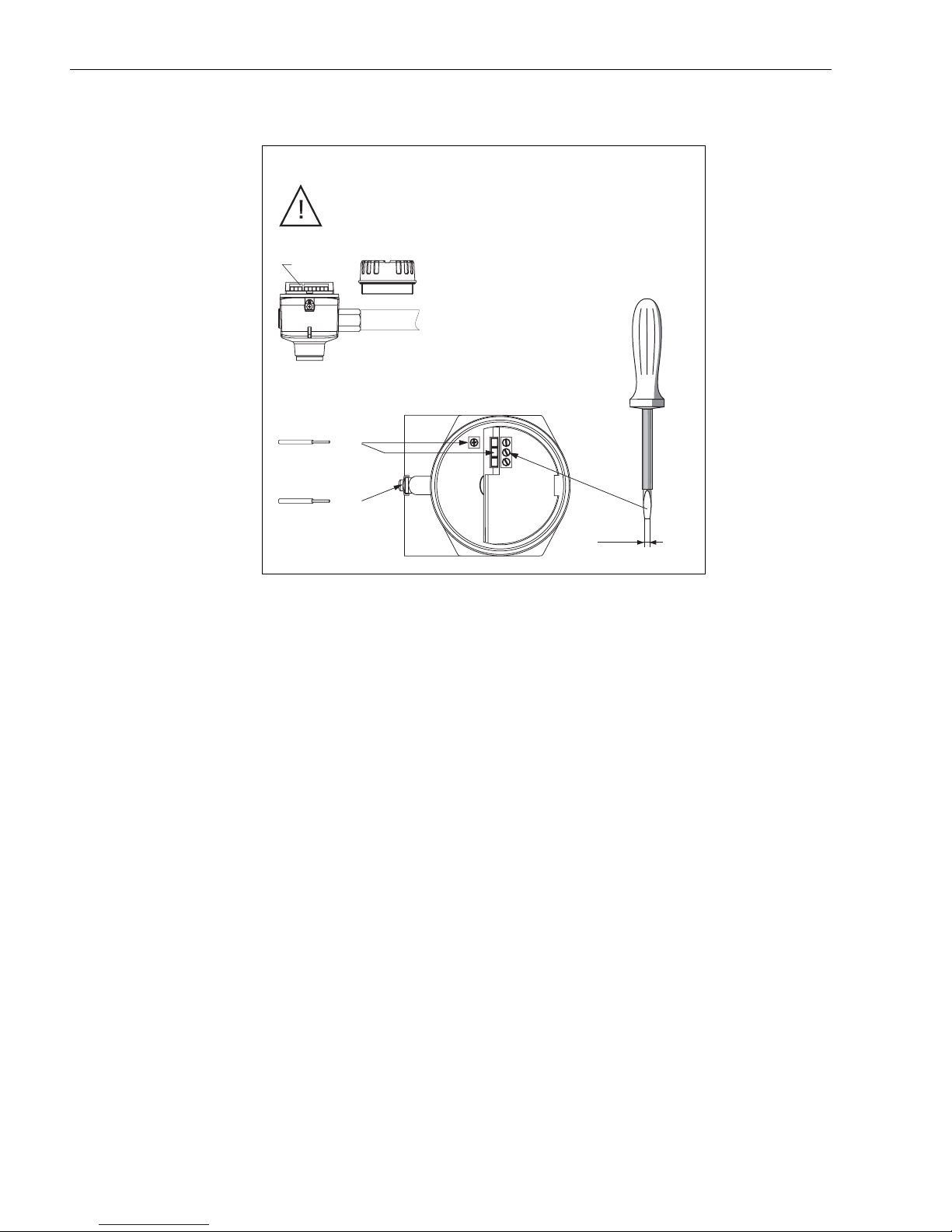
4.2 Connections, Function
Note national regulations!
FEL…
Max. AWG 14
(Max. )2,5 mm²
Max. AWG 12
(Max. )4 mm²
1/8 in
3 mm()
KA143Y29ae.eps
14 Endress+Hauser
Page 15
Liquiphant M FTL50 / FTL51 Operating Instructions
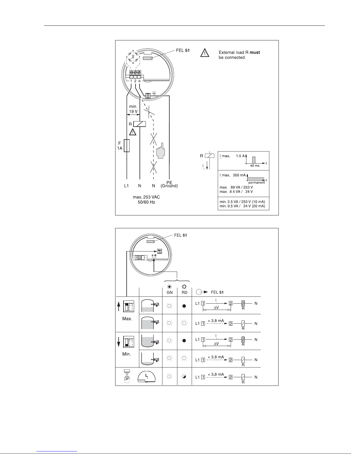
Connections FEL51
Two-wire AC connection
Function FEL51
KA143Y30ae.eps
Endress+Hauser 15
∆V
KA143Y39ae.eps
FEL51
max. 3V
Page 16
Operating Instructions Liquiphant M FTL50 / FTL51
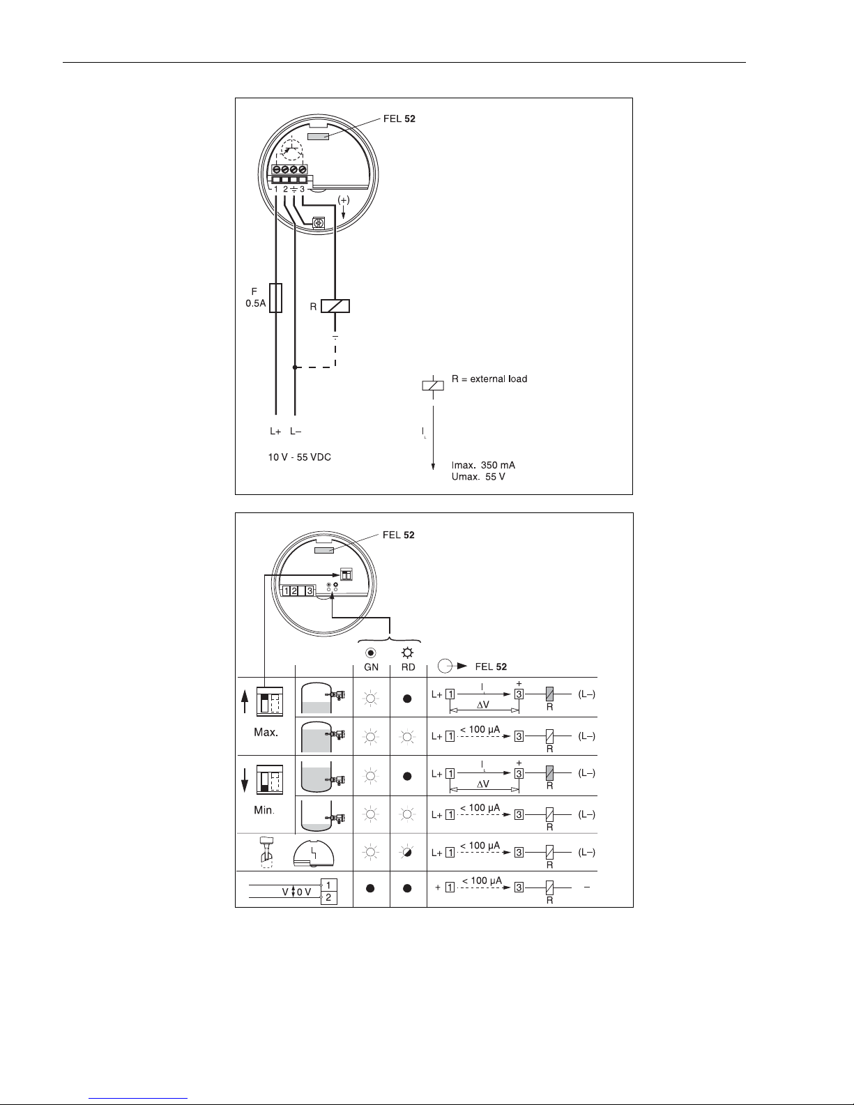
Connections FEL52
DC connection (PNP)
Function FEL52
KA143Y31ae.eps
16 Endress+Hauser
KA143Y40ae.eps
∆V
FEL52
max. 3V
Page 17
Liquiphant M FTL50 / FTL51 Operating Instructions
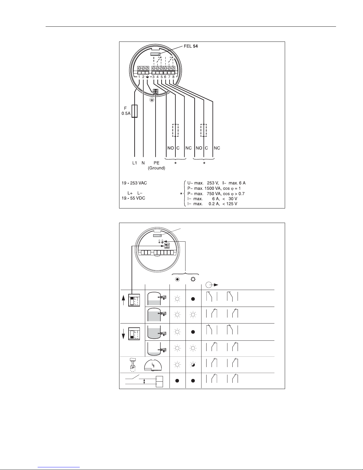
Connections FEL54
Universal connection
Relay output
Function FEL54
Max.
Min.
1 2 6 7 83 4 5
V 0 V
1
2
FEL 54
GN RD
354
354
354
3
3
3
KA143Y32ae.eps
FEL 54
687
687
687
4
4
4
7
5
5
5
8
6
7
8
6
7
8
6
KA143Y41ae.eps
Endress+Hauser 17
Page 18
Operating Instructions Liquiphant M FTL50 / FTL51
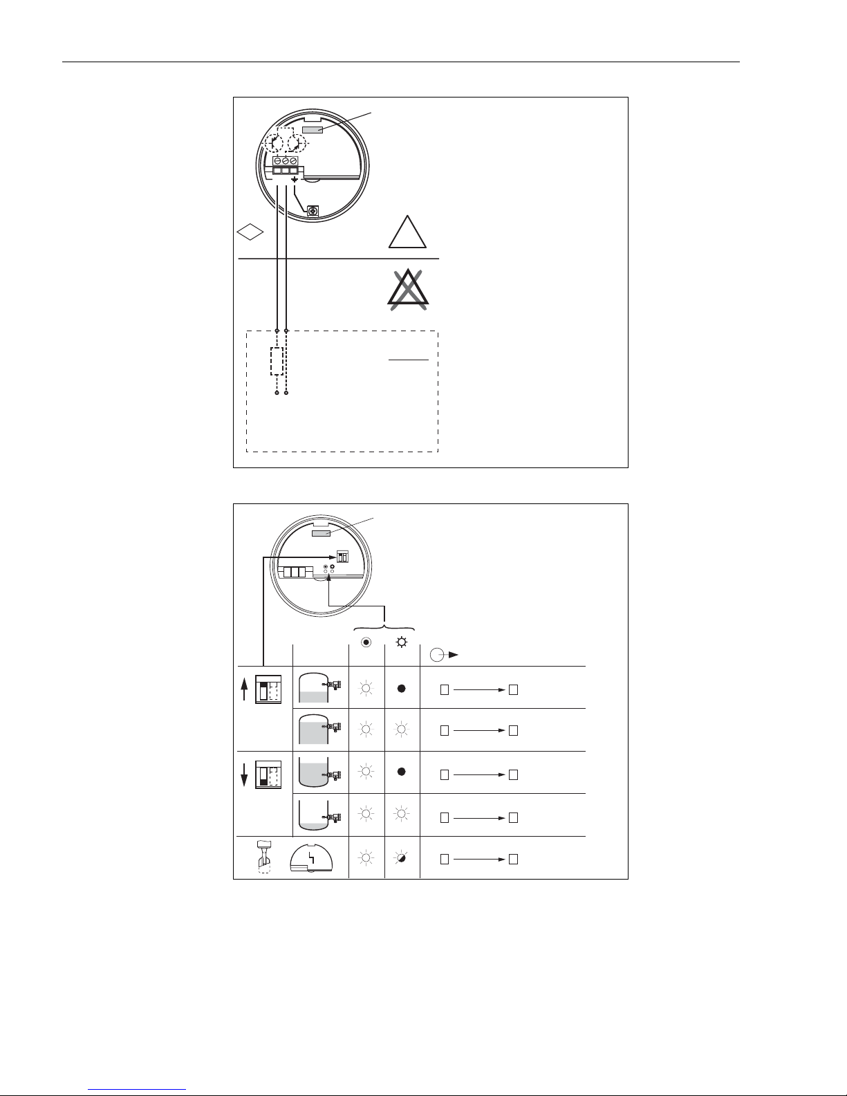
Connections FEL55
Output
8/16 mA
IS
FM
R
11 - 36 VDC
12
Non-Hazardous
Area
+–
FEL 55
R=
max
.
16.8 mA
E
E
11 V
X
X
Hazardous Area
e.g. PLC, AI modules
KA143Y33ae.eps
Function FEL55
Max.
Min.
1 2
FEL 55
GN RD
+ 2
+ 2
+ 2
+ 2
+ 2
FEL 55
~ 16 mA
~ 8 mA
~ 16 mA
~ 8 mA
< 3.6 mA
1
1
1
1
1
KA143Y42.eps
18 Endress+Hauser
Page 19
Liquiphant M FTL50 / FTL51 Operating Instructions
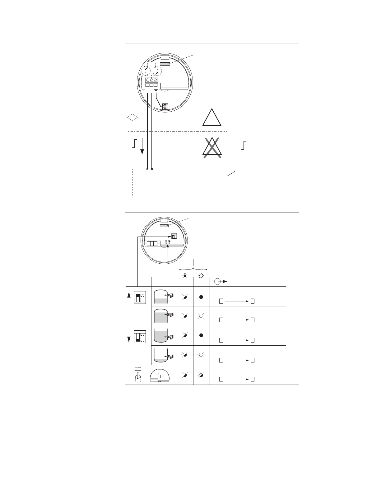
Connections FEL56
NAMUR output L-H
<1.0 mA / >2.2 mA
12
FEL 56
Function FEL56
FM
IS
H
I
L
e.g. FXN 421, FXN 422, SIN 100, SIN 110
FTL 325N, FTL 375N
Multiplexer: pulse cycle minimum 2 sduty
12
Non-Hazardous
Area
+–
FEL 56
GN RD
Max.
E
E
X
X
+2
+2
Hazardous
Area
H
2.2 - 2.8 mA
0.6 - 1.0 mAL
Isolating amplifier to
NAMUR (IEC 60947-5-6)
FEL 56
0.6…
1.0 mA
2.2…
2.8 mA
1
1
KA143Y34ae.eps
Endress+Hauser 19
Min.
+2
+2
+2
0.6…
1.0 mA
2.2…
2.8 mA
2.2…
2.8 mA
1
1
1
KA143Y43ae.eps
Page 20
Operating Instructions Liquiphant M FTL50 / FTL51
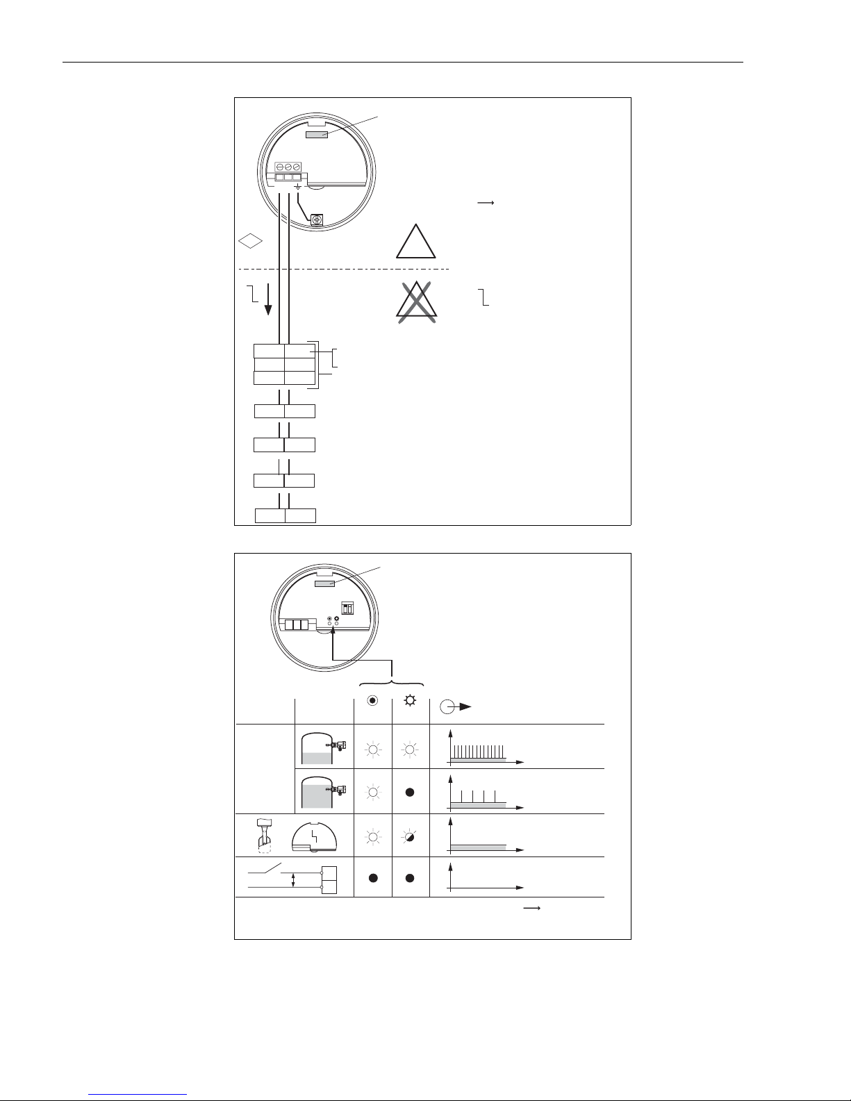
Connections FEL57
PFM output
FEL 57
150 Hz/50 Hz
Function FEL57
FM
H
f
L
37 38
z6 d6
12
IS
+–
78
33 34
d4 d2
z4 z2
21
E
Non-Hazardous
Area
Nivotester
FTL 320, FTL 120Z
FTL 325 P CH1
FTL 325 P CH3
FTL 370/372, FTL 170Z
FTL 375 P CH1
Input 1
FTL 372, FTL 170Z
FTL 375 P CH2
Input 2
FTL 375 P CH3
Input 3
Commutec S
SIF 101, SIF 111
E
FEL 57
X
X
Note function!
Hazardous
Area
H 150 Hz
See page 21
L
50 Hz
KA143Y35ae.eps
*
V0V
*Switch-on behavior
20 Endress+Hauser
1
2
GN YE
I
I
I
I
FEL 57
150 Hz
50 Hz
0Hz
0Hz
t
t
t
t
See page 21
KA143Y44ae.eps
Page 21
Liquiphant M FTL50 / FTL51 Operating Instructions
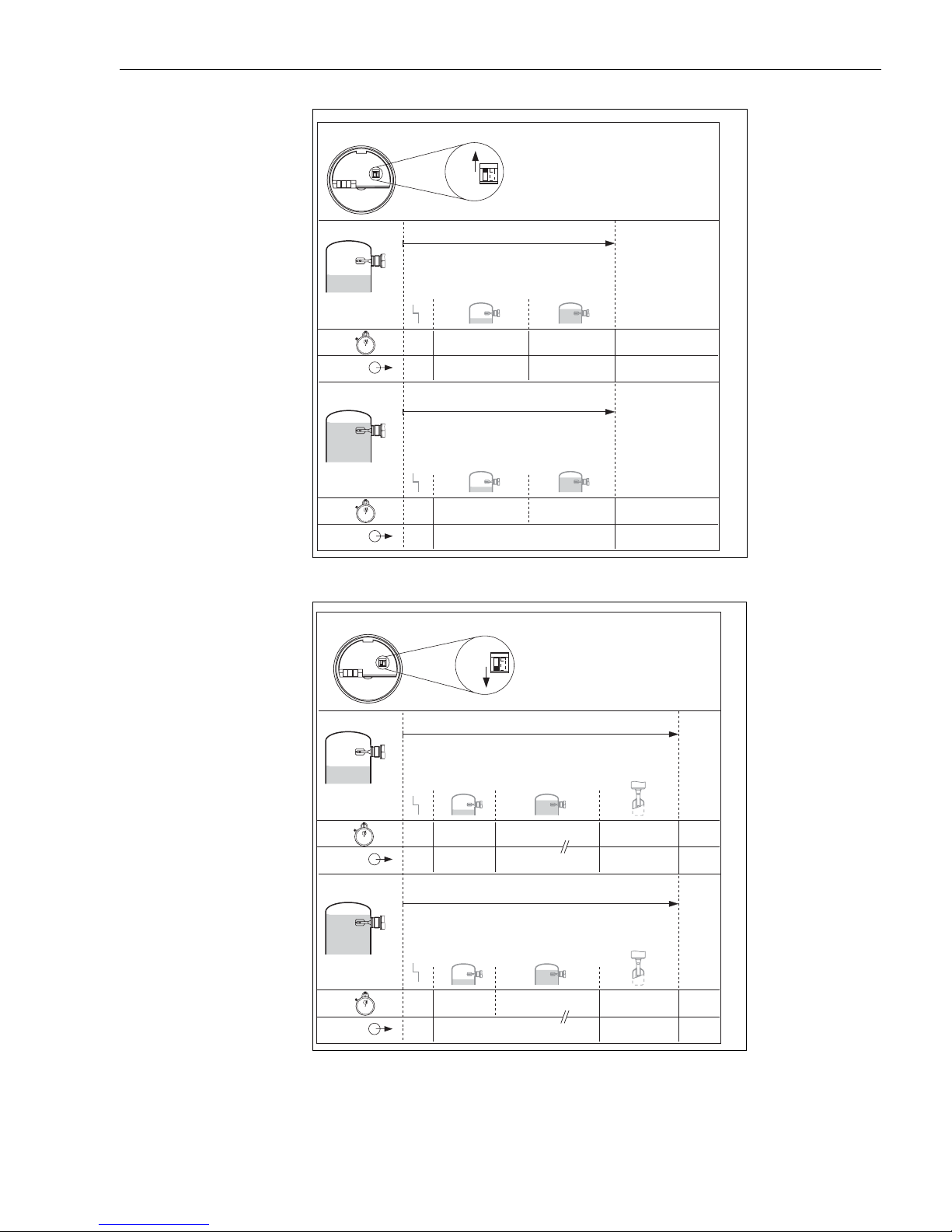
Switch-on behavior STD
(Self test)
FEL 57
FEL 57
STD
Simulation
1s 4s 3s
0 Hz 150 Hz 50 Hz 150 Hz
Simulation
Switch-on behavior EXT
(Self test)
FEL 57
FEL 57
1s 7s
0Hz 50Hz 50Hz
KA143Y45ae.eps
FEL 57
EXT
Simulation
1s 4s 30s 6s
0 Hz 150 Hz 50 Hz 0 Hz 150 Hz
Simulation
Endress+Hauser 21
FEL 57
1 s 34 s 6 s
0 Hz 50 Hz 0 Hz 50 Hz
KA143Y47ae.eps
Page 22
Operating Instructions Liquiphant M FTL50 / FTL51
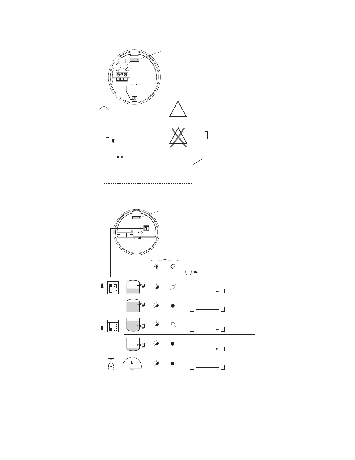
Connections FEL58
NAMUR output H-L
>2.2 mA / <1.0 mA
12
FEL 58
Function FEL58
FM
IS
H
I
L
e.g. FXN 421, FXN 422, SIN 100, SIN 110
FTL 325 N, FTL 375 N
Multiplexer: pulse cycle minimum 2 sduty
12
Non-Hazardous
Area
+–
FEL 58
GN YE
EX
E
X
Hazardous
Area
H
2.2 - 3.5 mA
0.6 - 1.0 mAL
Isolating amplifier to
NAMUR (IEC 60947-5-6)
FEL 58
KA143Y36ae.eps
Max.
Min.
22 Endress+Hauser
1Hz
1Hz
1Hz
1Hz
0.3 Hz
+2
+2
+2
+2
+2
2.2…
3.5 mA
0.6…
1.0 mA
2.2…
3.5 mA
0.6…
1.0 mA
< 1.0 mA
1
1
1
1
1
KA143Y49ae.eps
Page 23
Liquiphant M FTL50 / FTL51 Operating Instructions
Ex d
Ex d
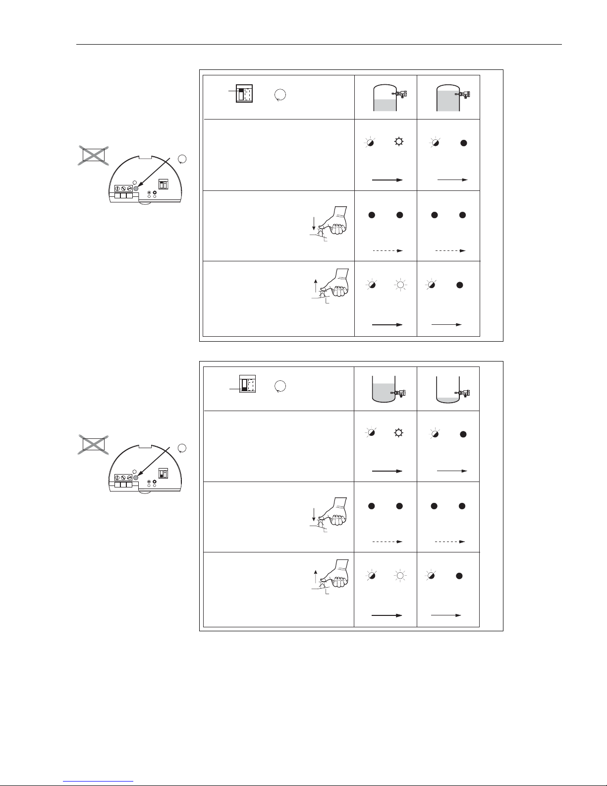
Function test button FEL58
Fail-safe mode MAX
MAX
1. Normal operation
+
T
GN
GN YE
YE
Ex d
T
*
T
Function test button FEL58
Fail-safe mode MIN
2. Press test button
3. Release the test button,
after ~2 s normal operation
+
MIN
1. Normal operation
T
>3 s
1Hz
2.2…
+
3.5 mA
2
GN YE
+
0mA
2
GN
1Hz
2.2…
+
3.5 mA
2
GN YE
YE
1
1
1
1Hz
0.6…
+
1.0 mA
2
GN YE
+
0mA
2
GN
1Hz
0.6…
+
1.0 mA
2
GN
YE
YE
1
1
1
KA143Y64ae.eps
Ex d
*
T
T
2. Press test button
3. Release the test button,
after ~2 s normal operation
>3 s
1Hz
2.2…
+
3.5 mA
2
GN YE
+
0mA
2
GN
1Hz
2.2…
+
3.5 mA
2
YE
1
1
1
1Hz
0.6…
+
1.0 mA
2
GN YE
+
0mA
2
GN
1Hz
0.6…
+
1.0 mA
2
1
1
YE
1
KA143Y65ae.eps
Endress+Hauser 23
Page 24
Operating Instructions Liquiphant M FTL50 / FTL51
5 Maintenance & Cleaning
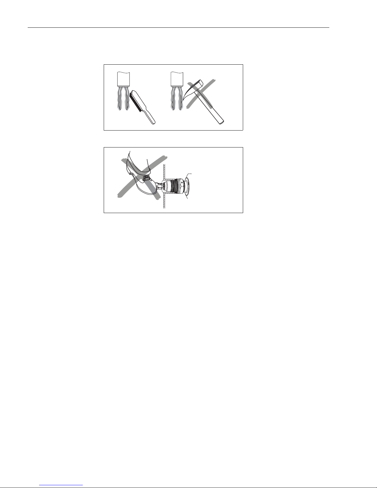
Removal of encrustation
KA143Y53ae.eps
Do not use as a step!
KA143Y54ae.eps
24 Endress+Hauser
Page 25
Liquiphant M FTL50 / FTL51 Operating Instructions
6 Technical Data
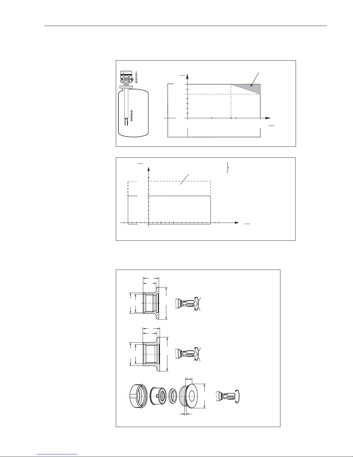
Ambient temperature T
Process temperature T
Process pressure p
e
Process temperature T
a
p
T
a
T
p
p
e
–58
–50()
psi
(bar)
1450
()100
928
64()
–14.5
–1()
p
–58
(–5 ) ( ) ( ) ( )
32
0()
T
a
°F
158 °F
()
70 °C
122 °F
()
50 °C
32 °F
°F 32 °F 194 °F 300 °F
0 °C 0 °C 90 °C 150 °C
–58 °F
(–50 °C)
FTL51FTL51-
# ### ### ##
# ### ### ##
300
150()
P
R
See order codes
T
()°F°C
p
Available when
used with temperature
spacer.
See order codes.
T
P
°F
KA143Y55ae.eps
KA143Y70ae.eps
6.1 Accessories
Weld-in sockets max. 360 psi/300°F
Ø1.26
(ø32)
Ø1.61
(ø41)
Dimensions are in inches (mm)
G¾
ISO 228
G1
ISO 228
1.02 (26)
0.83
(21)
1.16 (29.6)
0.97
(24.6)
Ø 2.16
(Ø55
Ø 2.36
(60Ø
G¾
E+H 52001052
-0.02
-0.4
)
G1
E+H 52001051
-0.02
-0.4
)
1.02
(26)
0.20 (5)
Ø 2.5
(65Ø
G1
E+H 52001221
-0.01
-0.3
)
(max. 25 bar/150°C)
max. 580 psi/210°F
(max. 40 bar/100°C)
KA143Y56ae.eps
Endress+Hauser 25
Page 26
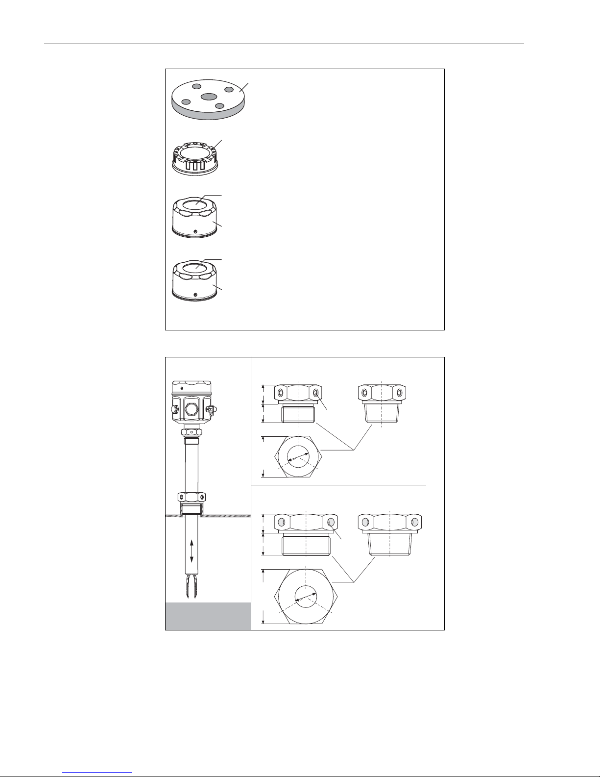
Operating Instructions Liquiphant M FTL50 / FTL51
Lap joint flanges with BSP 1
(G1) thread; Covers with
window
Corrosion-resistant steel
1.4571
(AISI 316 Ti)
Lap joint flange with G1 thread
2”, 150 psi, RF, ANSI B 16.5
E+H 918144-0000
Sliding sleeves for
unpressurized operation
PA 1 2
Glass
AISI 316 L
1.4435()
PC
AISI 316 L
()
1.4435
0.75
(19)
Transparent cover
For plastic housing
E+H 943461-0001
Stainless steel cover with glass window
For stainless steel housing
E+H 943301-1000
With polycarbonate window
E+H 52001403
G1
E+H 52003978
0.71
(18)
M6 (3x)
1 - 11½ NPT
E+H 52003979
KA143Y58ae.eps
See KA151F
(G 1, NPT 1)
See KA152F
(G 1½, NPT 1½)
p = 0 psi
e
(p = 0 bar)
e
max. 300 °F
(max. 150 °C)
0.75
(19)
1.61 (41)
0.87
(22)
2.16 (55)
Ø0.86
(21.8)
G1½
E+H 52003980
Ø0.86
(21.8)
1.4435
(AISI 316 L)
1½ - 11½ NPT
E+H 52003981
M6 (3x)
1.4435
(AISI 316 L)
KA143Y59ae.eps
26 Endress+Hauser
Page 27
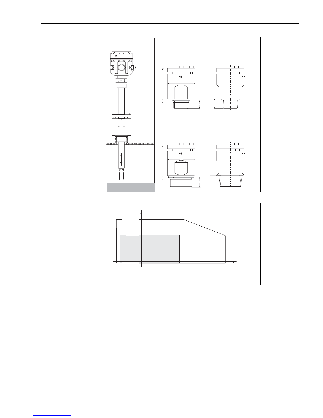
Liquiphant M FTL50 / FTL51 Operating Instructions
High pressure
sliding sleeves
G1
1.4435 (AISI 316 L)
E+H 52003663
Alloy C4
E+H 52003664
~2.75
(70)
0.08
(2)
G1½
1.4435 (AISI 316L)
E+H 52003665
Alloy C4
E+H 52003666
~2.83
(72)
0.08
(2)
Ø2.36 (60)
Ø2.36 (60)
0.71
(18)
0.86
(22)
1 - 11½ NPT
1.4435 (AISI 316 L)
E+H 52003667
Alloy C4
E+H 52003668
0.98
(25)
1½ - 11½ NPT
1.4435 (AISI 316L)
E+H 52003669
Alloy C4
E+H 52003670
0.98
(25)
See KA153F
(G 1, NPT 1)
See KA154F
(G 1½, NPT 1½)
KA143Y60ae.eps
High pressure
sliding sleeves:
Process pressure p
e
Process temperature T
psi
(bar)
p
1450 (100)
1160 (80)
928 (64)
Liquiphant S
Liquiphant M
-76
(-60)
-58
(-50)
-14.5 (-1)
32
(0)
300
(150)
500
(260)
540
(280)
°F (°C)
KA143Y69ae.eps
Endress+Hauser 27
Page 28

Operating Instructions Liquiphant M FTL50 / FTL51
7Troubleshooting
Fault Reason Remedy
Does not switch No power Check power
Faulty signal line Check signal line
Faulty electronic insert
– FEL51 connected directly to L1 and N
Density of liquid too low Set density to >0.5 at electronic insert
Fork encrusted Clean fork
Fork corroded
(Indication on FEL: red/yellow flashes,
FEL58: green flashes (0.3 Hz)
FEL51: Internal resistance of connected
relay too large
FEL51: Holding current of connected
relay too low
FEL54: Contacts welded together (after
short-circuit)
Switches incorrectly Min-/Max- fail-safe mode set wrong Set correct mode at electronic insert
Sporadic faulty
switching
Thick heavy foam, very turbulent
conditions, foaming liquid
Extreme RFI Use shielded cable
Extreme vibration Decouple, damp, turn fork 90°
Exchange
– always connect FEL51 via external load
Exchange fork and process connection
Connect suitable relay
Connected resistor in parallel with relay
Exchange FEL54; put fuse in contact circuit
Mount Liquiphant in bypass
Switches incorrectly
after power failure
Troubleshooting
Supplement
If the switching behavior of the fork is abnormal, the fork frequency can be measured at PIN 4 of
the diagnosis socket. With electronic inserts FEL 51/52/54/55/56/57/58, this is a sinusoidal
vibration whose amplitude makes it possible to determine the condition of the fork.
28 Endress+Hauser
Water in housing Screw cover and cable gland tight
FEL52: Output overloaded Reduce load, (cable) capacitance
FEL57: behavior during switch-on test
(functional test)
Observe switching behavior of FEL57; after
power failure block plant control for up to 45 s
Page 29
Liquiphant M FTL50 / FTL51 Operating Instructions
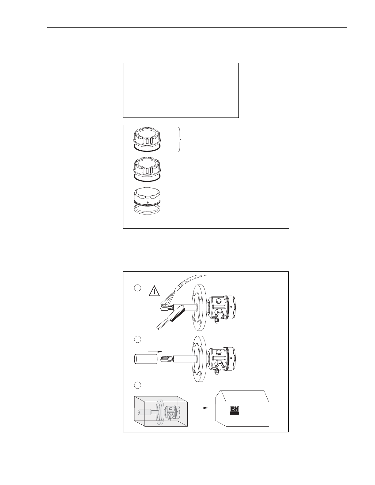
8 Spare Parts
Electronic inserts Installation specification:
Housing covers, seals
FEL51 52002304
FEL52 52002305
FEL54 52002306
FEL55 52002307
FEL56 52002308
FEL57 52002309
FEL58 52006454
Alu w/EPDM O-ring E+H 52002699
Alu
Alu (EX) w/EPDM O-ring E+H 52002698
EPDM
During installation, please keep in mind that
electrical resources (electronic inserts) which
are powered by non-intrinsically-safe circuits
may no longer be interconnected with intriniscally-safe circuits.
KA143Y61ae.eps
*
PBT-FR (cover only) E+H 943461-0000
EPDM O-ring E+H 017717-0003
*
AISI 304/316L E+H 943301-0000
(cover only)
(1.4301/1.4435)
*
Lubricate with silicone grease or graphite.
*
MVQ Silicone Seal E+H 943304-0000
KA143Y62ae.eps
Repair is done at
Endress+Hauser
9Repair
1.
2.
3.
Clean
Transport
protection
Endress+Hauser
KA143Y63ae.eps
Endress+Hauser 29
Page 30

Operating Instructions Liquiphant M FTL50 / FTL51
10 Supplemental Documentation
Technical Information
TI328F Liquiphant FTL50, FTL50H, FTL51, FTL51H
Notes on Safety
XA031F 4 0 II 1/2 G EEx d IIC/IIB
XA063F 4 0 II 1/2 G, II 1/2 D EEx ia/ib IIC/IIB
XA064F 4 0 II 1 G EEx ia IIC/IIB
XA108F 4 0 II 1/2 G EEx de IIC/IIB
XA154F 4 0 II 1/2 G, II 1/2 D EEx ia/ib IIC/IIB
XA159F 4 0 II 1 G EEx ia IIC/IIB
XA182F 4 0 II 3 G, II 3 D EEx nA/nC II
30 Endress+Hauser
Page 31

Liquiphant M FTL50 / FTL51 Operating Instructions
Endress+Hauser 31
Page 32

United States
Canada
Mexico
Endress+Hauser, Inc.
2350 Endress Place
Greenwood, IN 46143
Tel: 317-535-7138
Sales: 888-ENDRESS
Service: 800-642-8737
FAX: 317-535-8498
[email protected]
www.us.endress.com
Endress+Hauser Canada
1075 Sutton Drive
Burlington, ON L7L 5Z8
Tel: 905-681-9292
800-668-3199
FAX: 905-681-9444
www.ca.endress.com
Endress+Hauser (Mexico) S.A. de C.V.
Calle de Gustavo Baz No. 43
Fraccionamiento Bosques de Echegaray
CP 53310 Naucalpan de Juárez
Mexico
Tel: +52 55 5371 1110
FAX: +52 55 5371 1128
BA213F/24/ae/03.06
52005008
FM+SGML 6.0
Endress+Hauser Mexico, S.A. de C.V.
Av. Gustavo Baz No. 43
Fracc. Bosques de Echegaray
Naucalpan de Juaraz, C.P. 53310
Estada de Mexico
Mexico
Phone: (52)-55-5371-1110
FAX: (52)-55-5371-1128
E-mail: [email protected]
 Loading...