

Endress+Hauser Liquiphant FTL31 User Manual

Point level switch for liquids
Application
The Liquiphant FTL31 is a point level switch for liquids and is used in tanks, vessels
and pipes.
It is used for overfill prevention or pump protection in cleaning and filter systems as
well as in cooling and lubrication vessels, for instance.
Ideal for applications in which float switches or conductive, capacitance and optical
sensors have been used up to now. The Liquiphant FTL31 also works in areas where
these measuring principles are not suitable due to conductivity, buildup, turbulence,
flow conditions or air bubbles.
The Liquiphant FTL31 can be used for process temperatures up to:
• 100 °C (212 °F)
• 150 °C (302 °F)
Not suitable for hazardous areas.
The use of the Liquiphant FTL33 is recommended for hygiene areas.
Your benefits
• Operational safety, reliability and universal application thanks to the tuning fork
measuring principle
• Robust stainless steel housing (316L)
• External function test with test magnet
• Onsite function check possible thanks to LED indication
• Compact design for easy installation even in confined conditions or hard-to-access
areas
Products Solutions Services
Technical Information
Liquiphant FTL31
Vibronic
TI01147F/00/EN/02.14
71267728

Liquiphant FTL31
2 Endress+Hauser
Table of contents
Document information ....................... 3
Document conventions .......................... 3
Function and system design ................... 4
Measuring principle ............................ 4
Measuring system ............................. 4
Input ..................................... 5
Measured variable ............................. 5
Measuring range .............................. 5
Output ................................... 5
Switch output ................................ 5
Operating modes .............................. 5
Power supply .............................. 5
Supply voltage ............................... 5
Power consumption ............................ 5
Current consumption ........................... 5
Residual ripple ............................... 5
Electrical connection ........................... 6
Electronic version 3-wire DC-PNP ................... 7
Electronic version 2-wire AC/DC ................... 9
Overvoltage protection ......................... 10
Performance characteristics .................. 11
Reference operating conditions ................... 11
Switch point ................................ 11
Hysteresis ................................. 11
Non-repeatability ............................ 11
Influence of ambient temperature ................. 11
Influence of medium temperature .................. 11
Influence of medium pressure .................... 11
Switching delay .............................. 11
Switch-on delay ............................. 11
Measuring frequency .......................... 11
Measured error .............................. 11
Installation ............................... 12
Orientation ................................ 12
Installation instructions ........................ 12
Length of connecting cable ...................... 14
Environment .............................. 15
Ambient temperature range ..................... 15
Storage temperature .......................... 15
Climate class ............................... 15
Altitude ................................... 15
Degree of protection .......................... 16
Shock resistance ............................. 16
Vibration resistance ........................... 16
Electromagnetic compatibility .................... 16
Reverse polarity protection ...................... 16
Short-circuit protection ........................ 16
Process .................................. 17
Process temperature range ...................... 17
Process pressure range ......................... 17
Density ................................... 17
State of aggregation ........................... 17
Viscosity .................................. 17
Solids contents .............................. 17
Lateral loading capacity ........................ 17
Mechanical construction .................... 18
Design .................................... 18
Connector ................................. 19
Tuning fork ................................ 19
Sensor type ................................ 20
Weight ................................... 23
Materials .................................. 23
Surface roughness ............................ 23
Operability ............................... 24
LED display ................................ 24
Function test with test magnet .................... 24
Certificates and approvals ................... 25
CE mark ................................... 25
C-Tick symbol ............................... 25
Approval .................................. 25
Overfill prevention ............................ 25
Marine approvals ............................ 25
CRN approval ............................... 25
Inspection certificates .......................... 25
Manufacturer declarations ...................... 25
Pressure Equipment Directive .................... 25
Other standards and guidelines ................... 25
Ordering information ...................... 26
Product Configurator .......................... 26
Services (optional) ............................ 26
Accessories ............................... 27
Weld-in adapter ............................. 27
Plug-in jack, cable ............................ 27
Additional accessories ......................... 28
Supplementary documentation ............... 29
Operating Instructions ......................... 29
Additional documentation ...................... 29
Certificates ................................. 29
Liquiphant FTL31
Endress+Hauser 3
Document information
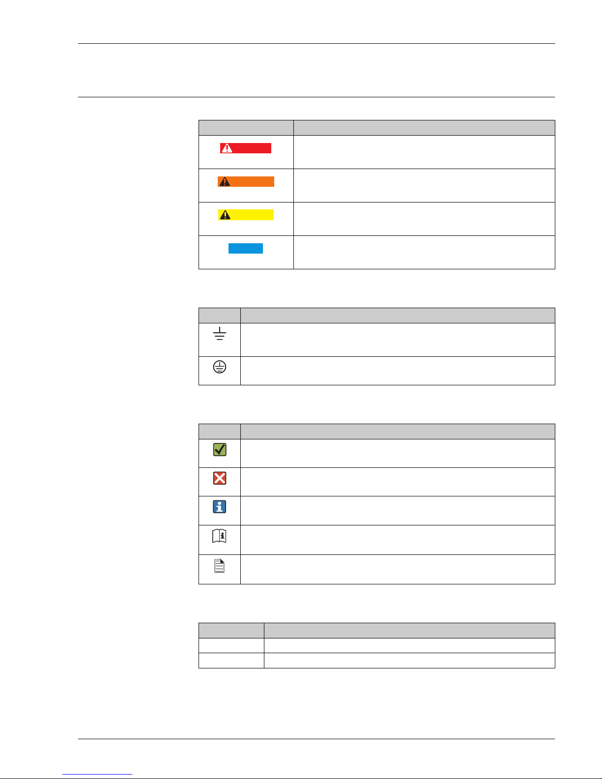
Document conventions Safety symbols
Symbol Meaning
DANGER
A0011189-EN
DANGER!
This symbol alerts you to a dangerous situation. Failure to avoid this situation
will result in serious or fatal injury.
WARNING
A0011190-EN
WARNING!
This symbol alerts you to a dangerous situation. Failure to avoid this situation
can result in serious or fatal injury.
CAUTION
A0011191-EN
CAUTION!
This symbol alerts you to a dangerous situation. Failure to avoid this situation
can result in minor or medium injury.
NOTICE
A0011192-EN
NOTE!
This symbol contains information on procedures and other facts which do not
result in personal injury.
Electrical symbols
Symbol Meaning
A0011200
Ground connection
A grounded terminal which, as far as the operator is concerned, is grounded via a grounding
system.
A0011199
Protective ground connection
A terminal which must be connected to ground prior to establishing any other connections.
Symbols for certain types of information
Symbol Meaning
A0011182
Permitted
Indicates procedures, processes or actions that are permitted.
A0011184
Forbidden
Indicates procedures, processes or actions that are forbidden.
A0011193
Tip
Indicates additional information.
A0011194
Reference to documentation
Refers to the corresponding device documentation.
A0011195
Reference to page
Refers to the corresponding page number.
Symbols in graphics
Symbol Meaning
1, 2, 3 ... Item numbers
A, B, C, ... Views
Liquiphant FTL31
4 Endress+Hauser
Function and system design
Measuring principle
A piezoelectric drive causes the tuning fork of the Liquiphant FTL31 to vibrate at its resonance
frequency. When the tuning fork is immersed in a liquid, its intrinsic frequency changes due to the
change in density of the surrounding medium. The electronics system in the point level switch
monitors the resonance frequency and indicates whether the tuning fork is vibrating in air or is
covered by liquid.
A signal is output via the DC-PNP or AC/DC electrical connection.
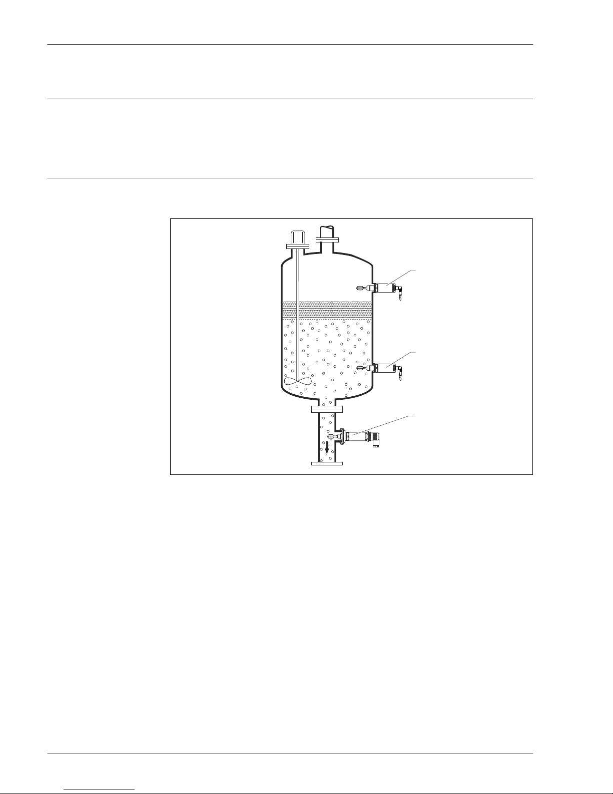
Measuring system
The measuring system consists of a Liquiphant FTL31 point level switch, e.g. for connection to
programmable logic controllers (PLC), a mini-contactor or solenoid valve.
2
1
3
A0020911
1 Overfill prevention or upper level detection MAX (maximum safety)
2 Lower level detection MIN (minimum safety)
3 Lower level detection MIN, e.g. dry running protection for pump

Liquiphant FTL31
Endress+Hauser 5
Input
Measured variable
Density
Measuring range
> 0.7 g/cm³ (optionally available: > 0.5 g/cm³)
Output
Switch output
Switching behavior: On/Off
Function
3-wire DC-PNP:
Positive voltage signal at the switch output of the electronics (PNP), switching capacity 200 mA
2-wire AC/DC:
Load switching in the power supply line, switching capacity 250 mA
Operating modes
The device has two operating modes: maximum safety (MAX) and minimum safety (MIN).
By choosing the corresponding operating mode, the user ensures that the device also switches in a
safety-oriented manner even in an alarm condition, e.g. if the power supply line is disconnected.
• Maximum safety (MAX)
The device keeps the electronic switch closed as long as the liquid level is below the fork. Sample
application: overfill prevention
• Minimum safety (MIN)
The device keeps the electronic switch closed as long as the fork is immersed in liquid. Sample
application: Dry running protection for pumps
The electronic switch opens if the limit is reached, if a fault occurs or the power fails (quiescent
current principle).
Power supply
Supply voltage
DC-PNP:
AC/DC:
10 to 30 V DC, 3-wire
20 to 253 V AC/DC, 2-wire
Power consumption
DC-PNP:
AC/DC:
< 975 mW
< 850 mW
Current consumption
DC-PNP:
AC/DC:
< 15 mA
< 3.8 mA
Residual ripple
DC-PNP:
AC/DC:
5 Vss 0 to 400 Hz
—
Liquiphant FTL31
6 Endress+Hauser
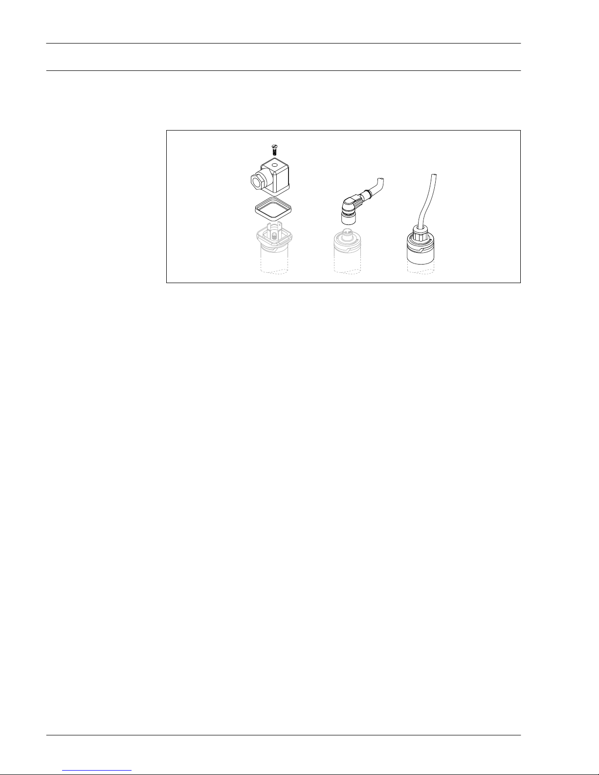
Electrical connection
Two electronic versions and three different connections are available for the device. A fine-wire fuse
is necessary for operation: 500 mA slow-blow.
Cable entry
A
B
C
A0020928
A Valve plug (M16x1.5; NPT ½"; QUICKON)
B M12 connector
C Cable 5 m (16 ft); 10 m (33 ft), captive when delivered, cannot be dismantled
Cable specification
• Valve plug
– Cable cross-section: max. 1.5 mm2 (AWG 16)
– Ø 3.5 to 8 mm (0.14 to 0.26 in)
• M12 connector: IEC 60947-5-2
• Cable (3LPE)
– Cable cross-section: 0.75 mm2 (AWG 20)
– Ø 6 to 8 mm (0.24 to 0.31 in)
– Material: PUR
Liquiphant FTL31
Endress+Hauser 7
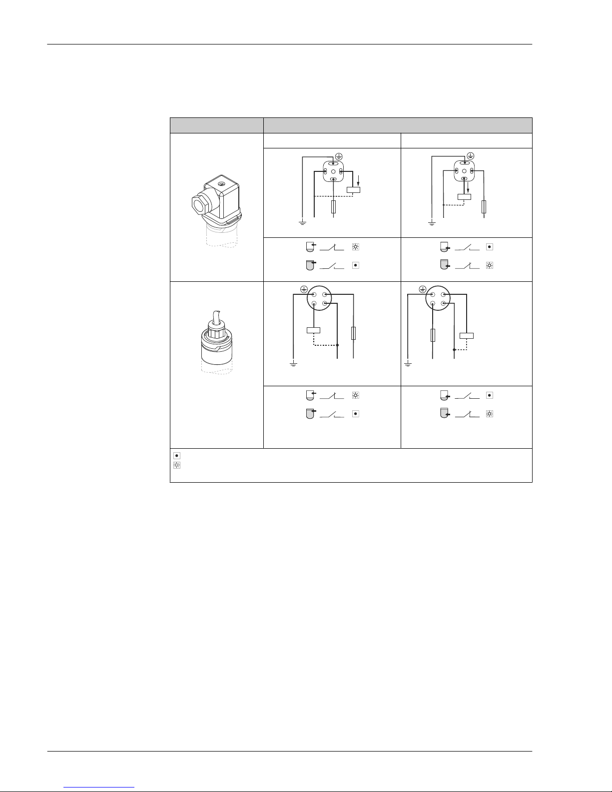
Electronic version 3-wire DCPNP
3-wire DC-PNP is preferably used in conjunction with programmable logic controllers (PLC), DI
modules as per EN 61131-2. Positive signal at the switch output of the electronics (PNP).
Voltage source: non-hazardous contact voltage or Class 2 circuit (North America).
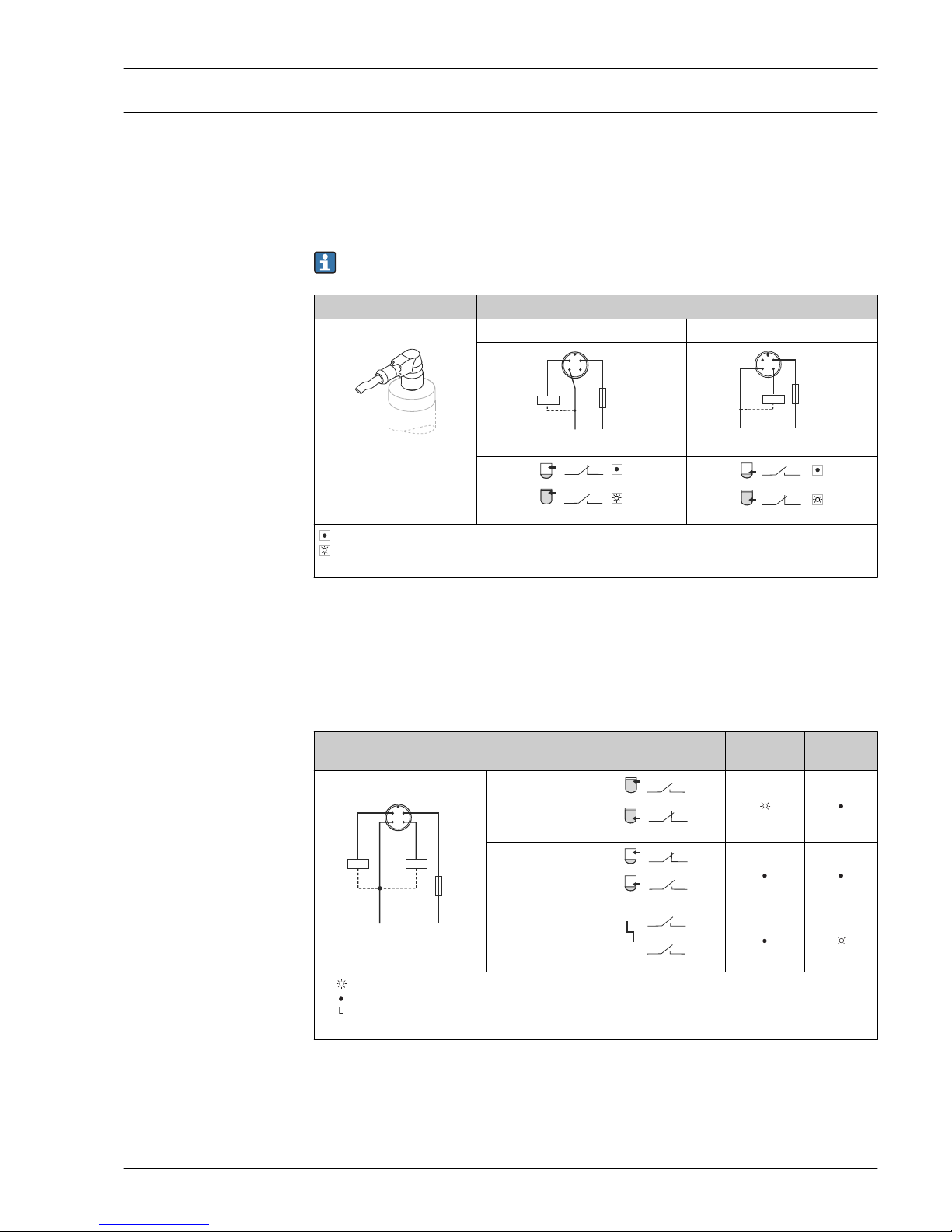
M12 connector
Depending on the analysis of the switch outputs, the device works in the MAX (maximum safety) or
MIN (minimum safety) mode.
A cable is optionally available for order, see "Accessories" section (→ 27).
Electrical connection Operating mode
M12 connector MAX MIN
A0022901
0.5A
L– L+
2
1
3
4
K
A0022858
0.5A
L–
L+
2
1
3
4
K
A0022859
1
21
2
A0021416
1
41
4
A0021417
K
Yellow LED (ye) not lit
Yellow LED (ye) lit
external load
Function monitoring with M12 connector
Using a two-channel analysis, function monitoring of the sensor can be implemented in addition to
level monitoring, e.g. per relay switch, PLC, AS-i Bus I/O module, …).
When both outputs are connected, the MIN and MAX outputs assume opposite states when the
device is operating fault-free (XOR). In the event of an alarm condition or a line break, both outputs
are deenergized.
Connection for function monitoring with antivalence
Yellow LED
(ye)
Red LED
(rd)
0.5A
L– L+
2
1
3
4
K1
K2
A0022917
Sensor covered
1
2
1
4
A0023016
Sensor exposed
4
1
1 2
A0023029
Fault
21
41
A0023030
K1 / K2
LED lit
LED not lit
Fault or warning
external load
Liquiphant FTL31
8 Endress+Hauser
Valve plug, cable
Depending on the assignment of the connector or the wiring of the cable, the device works in either
the MAX or MIN operating mode.
Electrical connection Operating mode
Valve plug MAX MIN
A0022900
1
3
0.5A
L–
L+
2
K
+
–
A0021724
L–
L+
3
0.5A
1
2
K
+
–
A0021723
3
23
2
A0021413
2
32
3
A0021414
Cable (cannot be
dismantled)
0.5A
1
2
3
L–
L+
K
+
A0022226
L+
0.5A
K
1
2
3
L–
+
A0022227
A0022902
Core colors:
1 = BK (black)
2 = GR (gray)
3 = BN (brown)
Ground = GNYE (greenyellow)
3
23
2
A0021413
2
32
3
A0021414
K
Yellow LED (ye) not lit
Yellow LED (ye) lit
external load
Liquiphant FTL31
Endress+Hauser 9
Electronic version 2-wire
AC/DC
The load is switched via an electronic switch directly in the power supply circuit. Always connect in
series with a load!
Not suitable for connection to low-voltage PLC inputs!
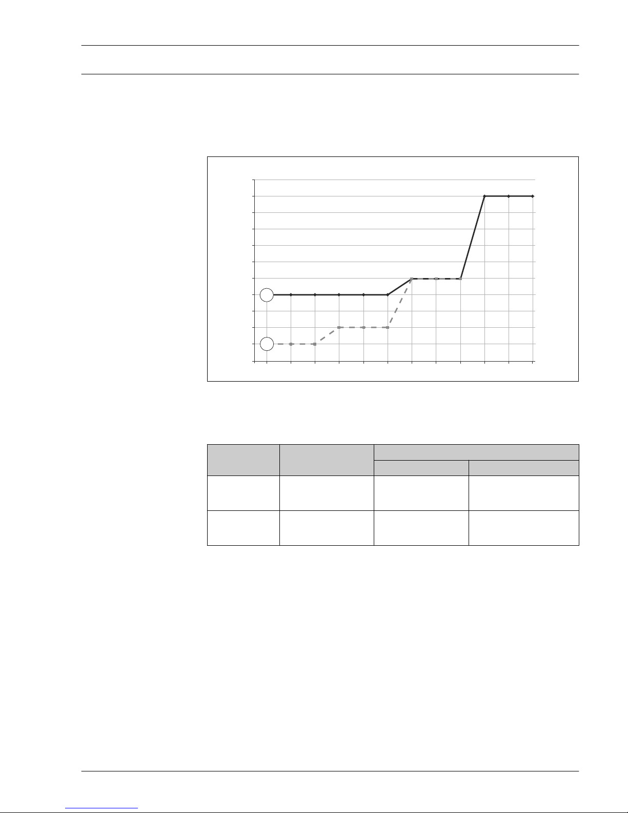
Selection tool for relays
2.7
2.5
2.3
2.1
1.9
1.7
1.5
1.3
1.1
0.9
0.7
0.5
20 24 27 43 48 53 60 110 121 207 230 253
P/S
U
P1
P2
A0023486
1 Minimum rated power of the load
P/S Rated power in [W] / [VA]
U Operating voltage in [V]
Position Supply voltage
Rated power
min max
P1
AC mode
24 V
110 V
230 V
> 1.3 VA
> 1.5 VA
> 2.5 VA
< 6 VA
< 27.5 VA
< 57.5 VA
P2
DC mode
24 V
48 V
60 V
> 0.7 W
> 0.9 W
> 1.5 W
< 6 W
< 12 W
< 15 W
Relays with a lower rated power can be operated by means of an RC module connected in parallel
(optional).
Liquiphant FTL31
10 Endress+Hauser
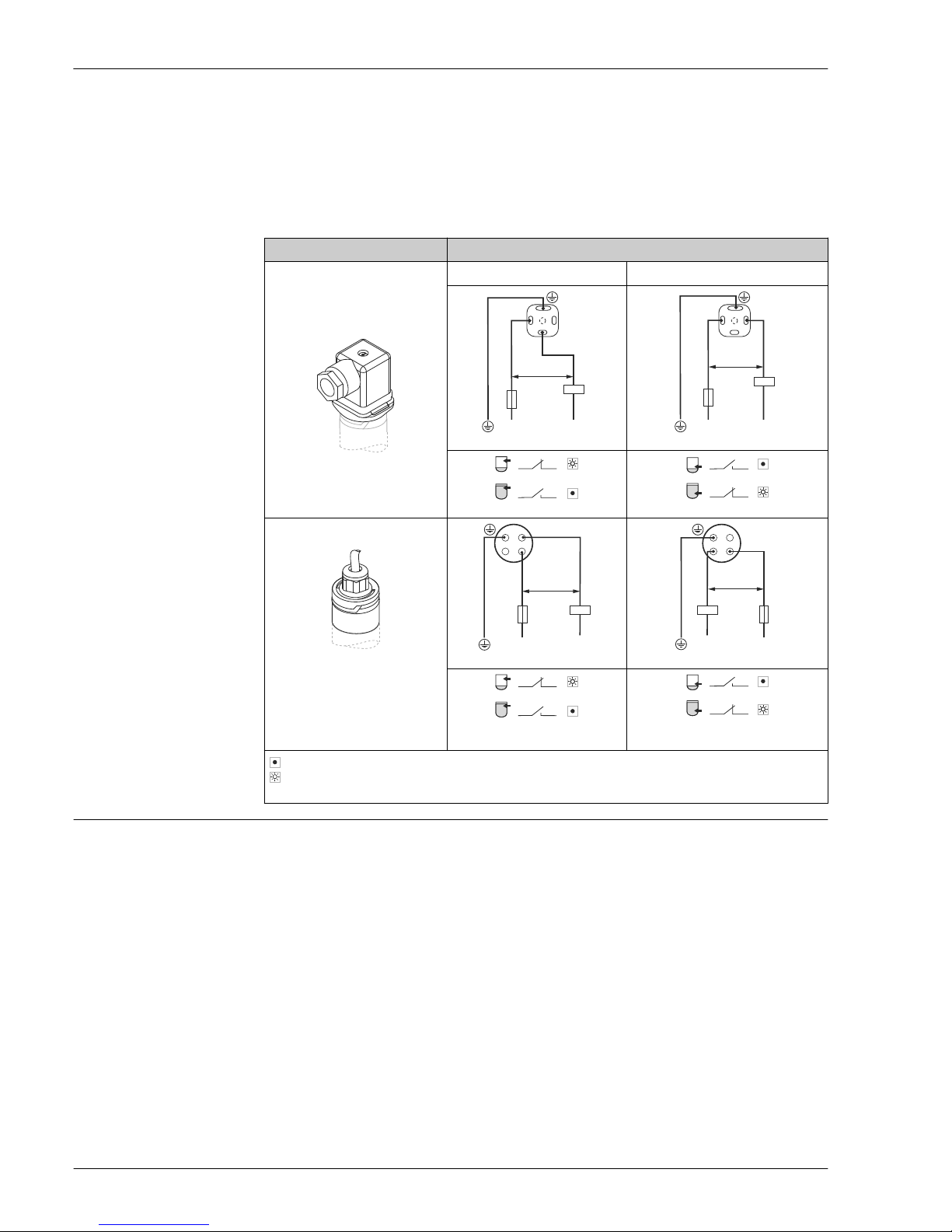
Valve plug, cable
Depending on the assignment of the connector or the wiring of the cable, the device works in either
the MAX or MIN operating mode.
When the cable is wired, one wire of the cable does not have any function in each of the operating
modes (brown in the case of MIN, and gray in the case of MAX). The cable with no function must be
secured against inadvertent contact.
Electrical connection Operating mode
Valve plug MAX MIN
A0022900
3
0.5A
1
K
>20 V
L1/L+ N/L–
A0021219
2
0.5A
1
K
>20 V
L1/L+ N/L–
A0021220
1313
A0021418
1212
A0021420
Cable (cannot be dismantled)
3
L1/L+
0.5A
K
>20 V
1
2
N/L–
A0022161
1
L1/L+
0.5A
K
2
3
N/L–
>20 V
A0022225
A0022902
Core colors:
1 = BK (black)
2 = GR (gray)
3 = BN (brown)
Ground = GNYE (green-yellow)
1313
A0021418
1212
A0021420
K
Yellow LED (ye) not lit
Yellow LED (ye) lit
external load
Overvoltage protection
Overvoltage category II
 Loading...