

Endress+Hauser Liquiline CM442, Liquiline CM444, Liquiline CM448 Operating Instructions Manual
Products Solutions Services
Operating Instructions
Liquiline CM442/CM444/CM448
Universal four-wire multichannel controller
Field device
BA00444C/07/EN/19.16
71309796
Valid as of version
01.06.00


Table of contents
Endress+Hauser 3
Table of contents
1 Document information .............. 5
1.1 Warnings ............................ 5
1.2 Symbols .............................. 5
1.3 Symbols at the device .................... 5
1.4 Documentation ........................ 6
2 Basic safety instructions ............ 7
2.1 Requirements for the personnel ............ 7
2.2 Designated use ........................ 7
2.3 Occupational safety ..................... 7
2.4 Operational safety ...................... 8
2.5 Product safety ......................... 8
3 Device description .................. 9
3.1 Housing closed ........................ 9
3.2 Housing open ......................... 9
3.3 Slot and port assignment ................ 10
3.4 Terminal diagram ..................... 11
4 Incoming acceptance and product
identification ..................... 12
4.1 Incoming acceptance ................... 12
4.2 Product identification ................... 12
4.3 Scope of delivery ...................... 13
4.4 Certificates and approvals ............... 13
5 Installation ....................... 14
5.1 Installation conditions .................. 14
5.2 Mounting measuring device .............. 15
5.3 Post-installation check .................. 18
6 Electrical connection .............. 19
6.1 Connection conditions .................. 19
6.2 Connecting the measuring device .......... 20
6.3 Connecting the sensors ................. 26
6.4 Connecting additional inputs, outputs or
relays .............................. 28
6.5 Connecting digital communication ......... 32
6.6 Hardware settings ..................... 35
6.7 Ensuring the degree of protection .......... 36
6.8 Post-connection check .................. 37
7 System integration ................ 38
7.1 Web server .......................... 38
7.2 Service interface ...................... 39
7.3 Fieldbuses ........................... 40
8 Operation options ................. 42
8.1 Overview ............................ 42
8.2 Access to the operating menu via the local
display ............................. 43
8.3 Configuration options .................. 44
9 Commissioning .................... 47
9.1 Function check ....................... 47
9.2 Power up ............................ 47
9.3 Basic setup .......................... 49
10 Operation ......................... 50
10.1 Display ............................. 50
10.2 General settings ....................... 52
10.3 Current inputs ........................ 64
10.4 Outputs ............................. 65
10.5 Binary inputs and outputs ............... 72
10.6 Additional functions ................... 78
11 Calibration ...................... 103
12 Diagnostics and troubleshooting .. 104
12.1 General troubleshooting ................ 104
12.2 Diagnostic information on the local display .. 105
12.3 Diagnostic information via web browser .... 105
12.4 Diagnostic information via fieldbus ........ 105
12.5 Adapting the diagnostic information ...... 105
12.6 Overview of diagnostic information ....... 107
12.7 Pending diagnostic messages ............ 110
12.8 Diagnostics list ...................... 110
12.9 Event logbook ....................... 111
12.10 Simulation ......................... 113
12.11 Device test .......................... 115
12.12 Resetting the measuring device .......... 115
12.13 Device information ................... 115
12.14 Firmware history ..................... 117
13 Maintenance .................... 120
13.1 Cleaning ........................... 120
14 Repairs .......................... 122
14.1 Spare parts ......................... 122
14.2 Return ............................. 125
14.3 Disposal ........................... 125
15 Accessories ...................... 126
15.1 Protective cover ...................... 126
15.2 Post mounting kit .................... 126
15.3 Measuring cable ..................... 126
15.4 Sensors ............................ 126
15.5 Additional functionality ................ 131
15.6 Software ........................... 133
15.7 Other accessories ..................... 133

Table of contents
4 Endress+Hauser
16 Technical data ................... 136
17 Installation and operation in
hazardous environment Class I Div.
2 (only CM442)(only CM444R and
CM448R) ........................ 148
Index ................................. 149
Liquiline CM442/CM444/CM448 Document information
Endress+Hauser 5
1 Document information
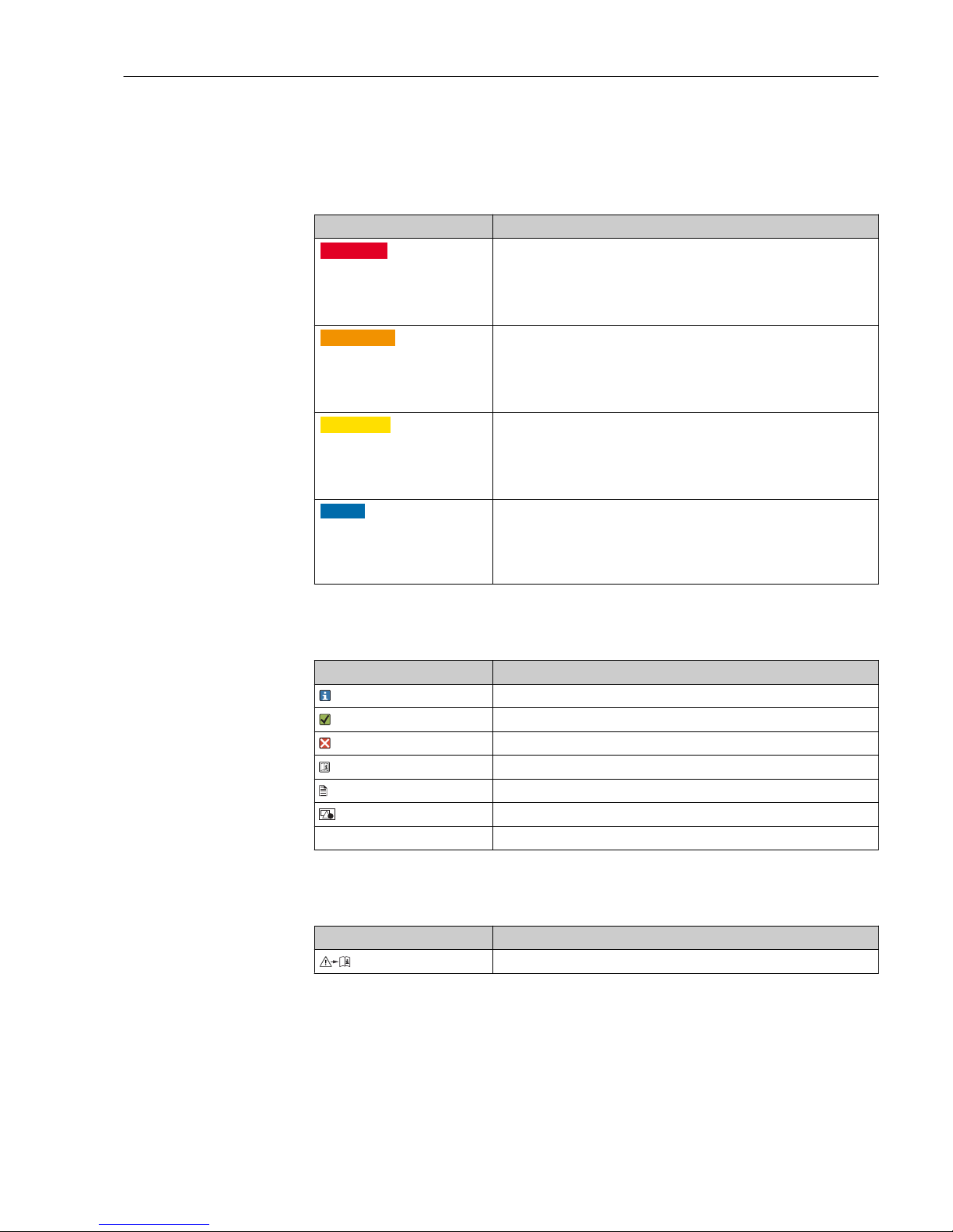
1.1 Warnings
Structure of information Meaning
L
DANGER
Causes (/consequences)
Consequences of non-compliance
(if applicable)
‣
Corrective action
This symbol alerts you to a dangerous situation.
Failure to avoid the dangerous situation will result in a fatal or serious
injury.
L
WARNING
Causes (/consequences)
Consequences of non-compliance
(if applicable)
‣
Corrective action
This symbol alerts you to a dangerous situation.
Failure to avoid the dangerous situation can result in a fatal or serious
injury.
L
CAUTION
Causes (/consequences)
Consequences of non-compliance
(if applicable)
‣
Corrective action
This symbol alerts you to a dangerous situation.
Failure to avoid this situation can result in minor or more serious injuries.
NOTICE
Cause/situation
Consequences of non-compliance
(if applicable)
‣
Action/note
This symbol alerts you to situations which may result in damage to
property.
1.2 Symbols
Symbol Meaning
Additional information, tips
Permitted or recommended
Not permitted or not recommended
Reference to device documentation
Reference to page
Reference to graphic
Result of a step
1.3 Symbols at the device
Symbol Meaning
Reference to device documentation

Document information Liquiline CM442/CM444/CM448
6 Endress+Hauser
1.4 Documentation
The following instructions complement these Operating Instructions and are available on
the product pages on the internet:
• Brief Operating Instructions for Liquiline CM44x, KA01159C
• Operating Instructions for Memosens, BA01245C
– Software description for Memosens inputs
– Calibration of Memosens sensors
– Sensor-specific diagnostics and troubleshooting
• Operating Instructions for HART communication, BA00486C
– Onsite settings and installation instructions for HART
– Description of HART driver
• Guidelines for communication via fieldbus and web server
– HART, SD01187C
– PROFIBUS, SD01188C
– Modbus, SD01189C
– Web server, SD01190C
– EtherNet/IP, SD01293C

Liquiline CM442/CM444/CM448 Basic safety instructions
Endress+Hauser 7
2 Basic safety instructions
2.1 Requirements for the personnel
• Installation, commissioning, operation and maintenance of the measuring system may
be carried out only by specially trained technical personnel.
• The technical personnel must be authorized by the plant operator to carry out the
specified activities.
• The electrical connection may be performed only by an electrical technician.
• The technical personnel must have read and understood these Operating Instructions
and must follow the instructions contained therein.
• Measuring point faults may be repaired only by authorized and specially trained
personnel.
Repairs not described in the Operating Instructions provided may only be carried out
directly by the manufacturer or by the service organization.
2.2 Designated use
2.2.1 Non-hazardous atmosphere
Liquiline CM44x is a multichannel controller for connecting digital sensors with
Memosens technology in non-hazardous locations.
The device is designed for use in the following applications:
• Water and wastewater
• Power stations
• Chemical industry
• Other industrial applications
2.2.2 Hazardous location as per FM/CSA Class I Div. 2 (CM442 only)
‣
Pay attention to the control drawing and the specified operating conditions in the
appendix to this manual and follow the instructions.
2.2.3 Non-designated use
Use of the device for any purpose other than that described, poses a threat to the safety of
people and of the entire measuring system and is therefore not permitted.
The manufacturer is not liable for damage caused by improper or non-designated use.
2.3 Occupational safety
As the user, you are responsible for complying with the following safety conditions:
• Installation guidelines
• Local standards and regulations
• Regulations for explosion protection
Electromagnetic compatibility
• The product has been tested for electromagnetic compatibility in accordance with the
applicable European standards for industrial applications.
• The electromagnetic compatibility indicated applies only to a product that has been
connected in accordance with these Operating Instructions.

Basic safety instructions Liquiline CM442/CM444/CM448
8 Endress+Hauser
2.4 Operational safety
1. Before commissioning the entire measuring point, verify that all connections are
correct. Ensure that electrical cables and hose connections are undamaged.
2. Do not operate damaged products, and safeguard them to ensure that they are not
operated inadvertently. Label the damaged product as defective.
3. If faults cannot be rectified:
Take the products out of operation and safeguard them to ensure that they are not
operated inadvertently.
L
CAUTION
Cleaning not switched off during calibration or maintenance activities
Risk of injury due to medium or cleaning agent
‣
If a cleaning system is connected, switch if off before removing a sensor from the
medium.
‣
If you wish to check the cleaning function and have therefore not switched off the
cleaning system, please wear protective clothing, goggles and gloves or take other
appropriate measures.
2.5 Product safety
2.5.1 State of the art
The product is designed to meet state-of-the-art safety requirements, has been tested, and
left the factory in a condition in which it is safe to operate. The relevant regulations and
European standards have been observed.
2.5.2 IT security
We only provide a warranty if the device is installed and used as described in the
Operating Instructions. The device is equipped with security mechanisms to protect it
against any inadvertent changes to the device settings.
IT security measures in line with operators' security standards and designed to provide
additional protection for the device and device data transfer must be implemented by the
operators themselves.
Liquiline CM442/CM444/CM448 Device description
Endress+Hauser 9
3 Device description
3.1 Housing closed
1 2
3
4
5
6
A0025813
1 Mounted on a post
1 Display
2 Weather protection cover (optional)
3 Navigator
4 Sensor cable or current output cable
5 Power supply cable
6 Soft keys, assignment depends on menu
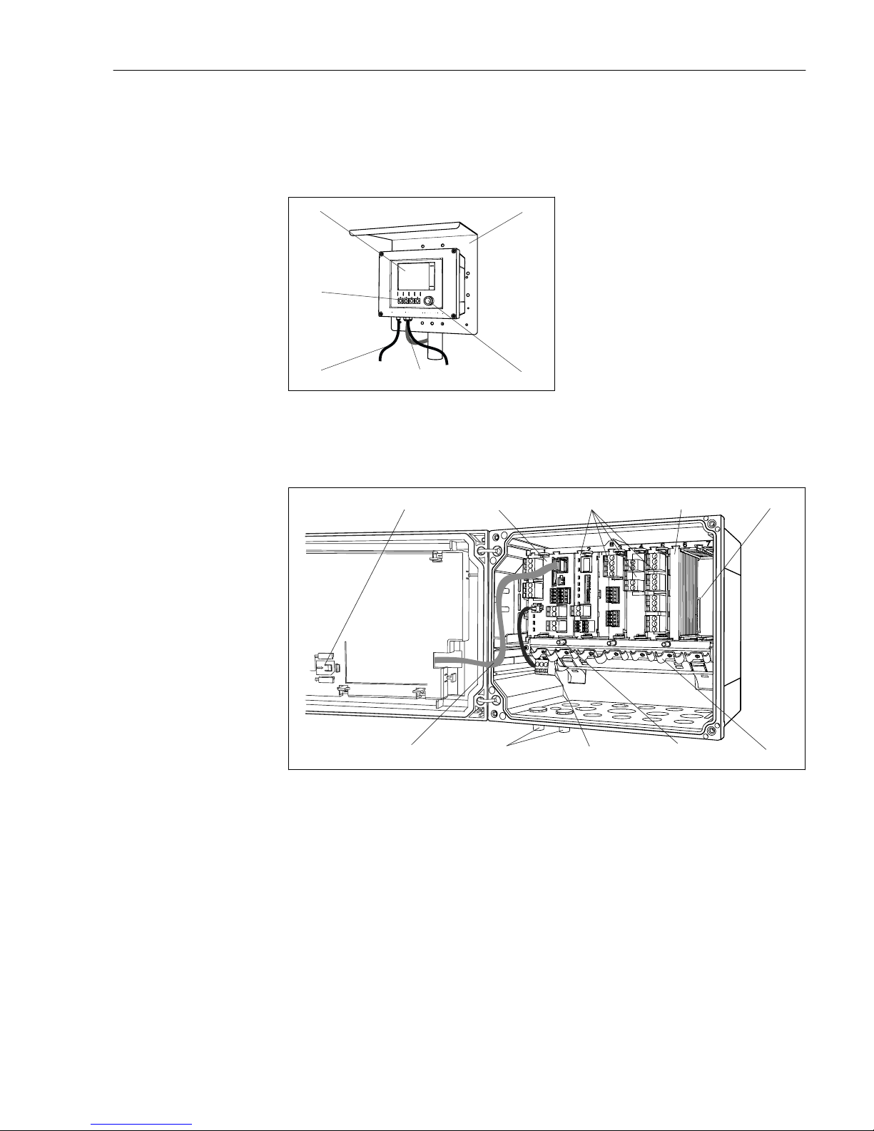
3.2 Housing open
1
2
3
4 5
6
789
10
A0025814
2 Example of a four-channel device with an open display cover (without wiring)
1 Storage slot for SD card 6 Cable mounting rail
2 Basic module 7 Threaded bolt for protective ground connection
3 Extension modules (optional) 8 Extension power unit with internal cable
4 Shock protection, dummy cover and end cover 9 M12 connectors for sensor connection
(optional)
5 Extension backplane 10 Display cable
Device description Liquiline CM442/CM444/CM448
10 Endress+Hauser
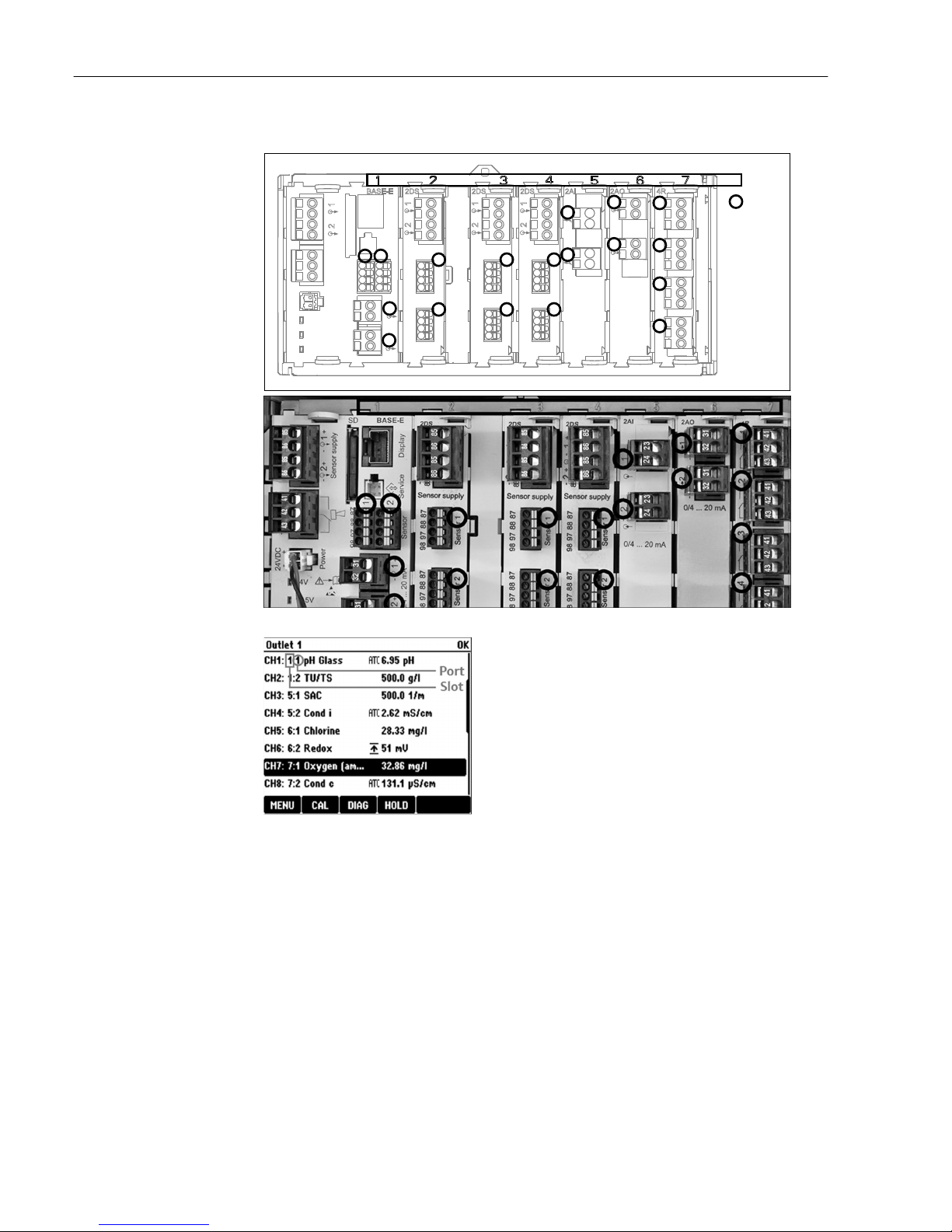
3.3 Slot and port assignment
Slots
1
2
1
2
1
2
1
2
Ports
BASE-E
2DS 2DS 2DS 2AI 2AO 4R
1
2
Sensor 1
Sensor 1
Sensor 1
Sensor 2
Sensor 2
Sensor 2
1
2
1
2
1
2
1
2
3
4
3 Slot and port assignment of the hardware modules
4 Slot and port assignment on the
display
• Inputs are assigned to measuring channels in the
ascending order of the slots and ports.
Adjacent example:
"CH1: 1:1 pH glass" means:
Channel 1 (CH1) is slot 1 (basic module) : Port 1 (input
1), pH glass sensor
• Outputs and relays are named according to their
function, e.g. "current output", and are displayed with the
slot and port numbers in ascending order
Liquiline CM442/CM444/CM448 Device description
Endress+Hauser 11
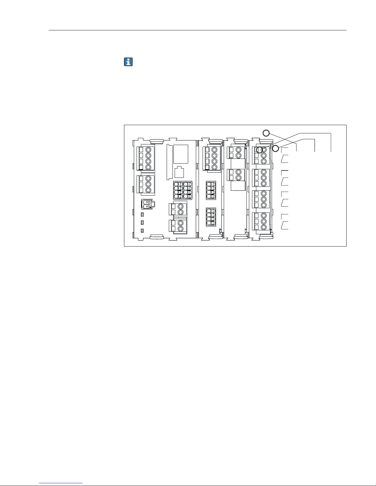
3.4 Terminal diagram
The unique terminal name is derived from:
Slot no. : Port no. : Terminal
Example, NO contact of a relay
Device with 4 inputs for digital sensors, 4 current outputs and 4 relays
• Base module BASE-E (contains 2 sensor inputs, 2 current outputs)
• Module 2DS (2 sensor inputs)
• Module 2AO (2 current outputs)
• Module 4R (4 relays)
1 2
3
4
43
42 41
43
42 41
43
42 41
43
42 41
Relay 1
Relay 2
Relay 3
Relay 4
Slot
Slot 4
Port 1
Pin 41
A0025105
5 Creating a terminal diagram using the example of the NO contact (terminal 41) of a relay

Incoming acceptance and product identification Liquiline CM442/CM444/CM448
12 Endress+Hauser
4 Incoming acceptance and product
identification
4.1 Incoming acceptance
1. Verify that the packaging is undamaged.
Notify your supplier of any damage to the packaging.
Keep the damaged packaging until the matter has been settled.
2. Verify that the contents are undamaged.
Notify your supplier of any damage to the delivery contents.
Keep the damaged products until the matter has been settled.
3. Check the delivery for completeness.
Check it against the delivery papers and your order.
4. Pack the product for storage and transportation in such a way that it is protected
against impact and moisture.
The original packaging offers the best protection.
The permitted ambient conditions must be observed (see "Technical data").
If you have any questions, please contact your supplier or your local sales center.
4.2 Product identification
4.2.1 Nameplate
The nameplate provides you with the following information on your device:
• Manufacturer identification
• Order code
• Extended order code
• Serial number
• Firmware version
• Ambient and process conditions
• Input and output values
• Activation codes
• Safety information and warnings
‣
Compare the data on the nameplate with your order.
4.2.2 Product identification
Product page
www.endress.com/cm442
www.endress.com/cm444
www.endress.com/cm448
Interpreting the order code
The order code and serial number of your product can be found in the following locations:
• On the nameplate
• In the delivery papers
Obtaining information on the product
1. Go to the product page for your product on the Internet.

Liquiline CM442/CM444/CM448 Incoming acceptance and product identification
Endress+Hauser 13
2. At the bottom of the page, select the "Online Tools" link followed by "Check your
device features".
An additional window opens.
3. Enter the order code from the nameplate into the search field, and then select "Show
details".
You will receive information on each feature (selected option) of the order code.
4.3 Scope of delivery
The scope of delivery comprises:
• 1 multichannel controller in the version ordered
• 1 mounting plate
• 1 wiring label (attached at the factory to the inside of the display cover)
• 1 printed copy of the Brief Operating Instructions in the language ordered
If you have any questions, please contact your supplier or your local sales center.
4.4 Certificates and approvals
4.4.1
mark
The product meets the requirements of the harmonized European standards. As such, it
complies with the legal specifications of the EC directives. The manufacturer confirms
successful testing of the product by affixing to it the mark.
4.4.2 EAC
The product has been certified according to guidelines TP TC 004/2011 and TP TC
020/2011 which apply in the European Economic Area (EEA). The EAC conformity mark
is affixed to the product.
4.4.3 cCSAus
The product complies with "CLASS 2252 05 - Process Control Equipment" and "CLASS 2252
85 - Process Control Equipment - Certified to US Standards" requirements.
4.4.4 FM/CSA
CM442 only
The device has been developed and tested according to the following standards:
• FM3600 (2011)
• FM3611 (2010)
• FM3810 (2005)
• ANSI/ISA NEMA250 (1991)
• ANSI/IEC 60529 (2001)
4.4.5 MCERTS
CM442 only
The device has been assessed by Sira Certification Service and complies with "MCERTS
Performance Standards for Continuous Water Monitoring Equipment, Part 2: online
analysers, Version 3.1, dated August 2010"; Certificate No.: Sira MC140246/01.
Installation Liquiline CM442/CM444/CM448
14 Endress+Hauser
5 Installation
5.1 Installation conditions
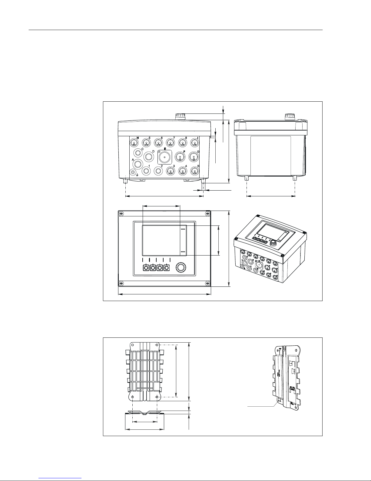
5.1.1 Dimensions
H 5 6 7 8 I
GF
E
D
C
A
1 2 3 4 B
162 (6.38)
14 (0.55)
Ø4 (0.16)
Ø9 (0.35)
199 (7.38) 128 (5.04)
237 (9.33)
194 (7.64)
76 (2.99)
95 (3.74)
A0012396
6 Dimensions of field housing in mm (inch)
5.1.2 Mounting plate
80 (3.15)
190 (7.48)
3 (0.12)
4 x 6.5 (0.26)
170 (6.69)
125 (4.92)
A0012426
7 Mounting plate in mm (inch)
Liquiline CM442/CM444/CM448 Installation
Endress+Hauser 15
5.1.3 Protective cover
NOTICE
Effect of climatic conditions (rain, snow, direct sunlight etc.)
Impaired operation to complete transmitter failure
‣
When installing outside, always use the weather protection cover (accessory).
320 (12.6)
270 (10.6)
300 (11.8)
80 (3.15)
170 (6.69)
170 (6.69)
80 (3.15)
8 x Ø 7 (0.28)
A0012428
8 Weather protection cover in mm (inch)
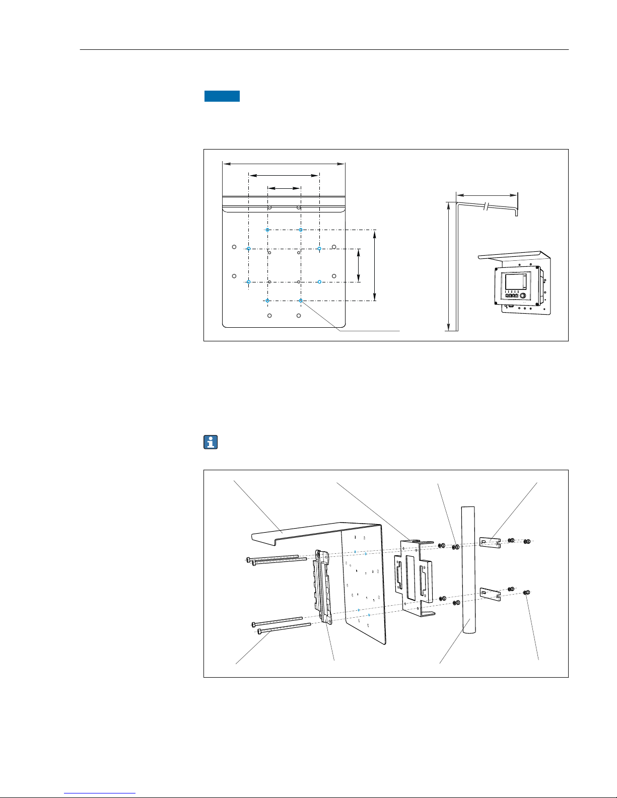
5.2 Mounting measuring device
5.2.1 Post mounting
You require the post mounting kit (optional) to mount the unit on a pipe, post or
railing (square or circular, span range 20 to 61 mm (0.79 to 2.40")).
1 2
3
4
56
7
8
A0012665
9 Post mounting
1 Weather protection cover (optional) 5 Spring washers, nuts (post mounting kit)
2 Post mounting plate (post mounting kit) 6 Pipe or railing (circular/square)
3 Spring washers, nuts (post mounting kit) 7 Mounting plate
4 Pipe clamps (post mounting kit) 8 Threaded rods (post mounting kit)
Installation Liquiline CM442/CM444/CM448
16 Endress+Hauser
A0025884
10 Post mounting
A0025885
11 Attach the device and click it into place
1. Bring the device to the mounting plate.
2. Slide the device downwards in the guide on the mounting rail until it clicks into place.
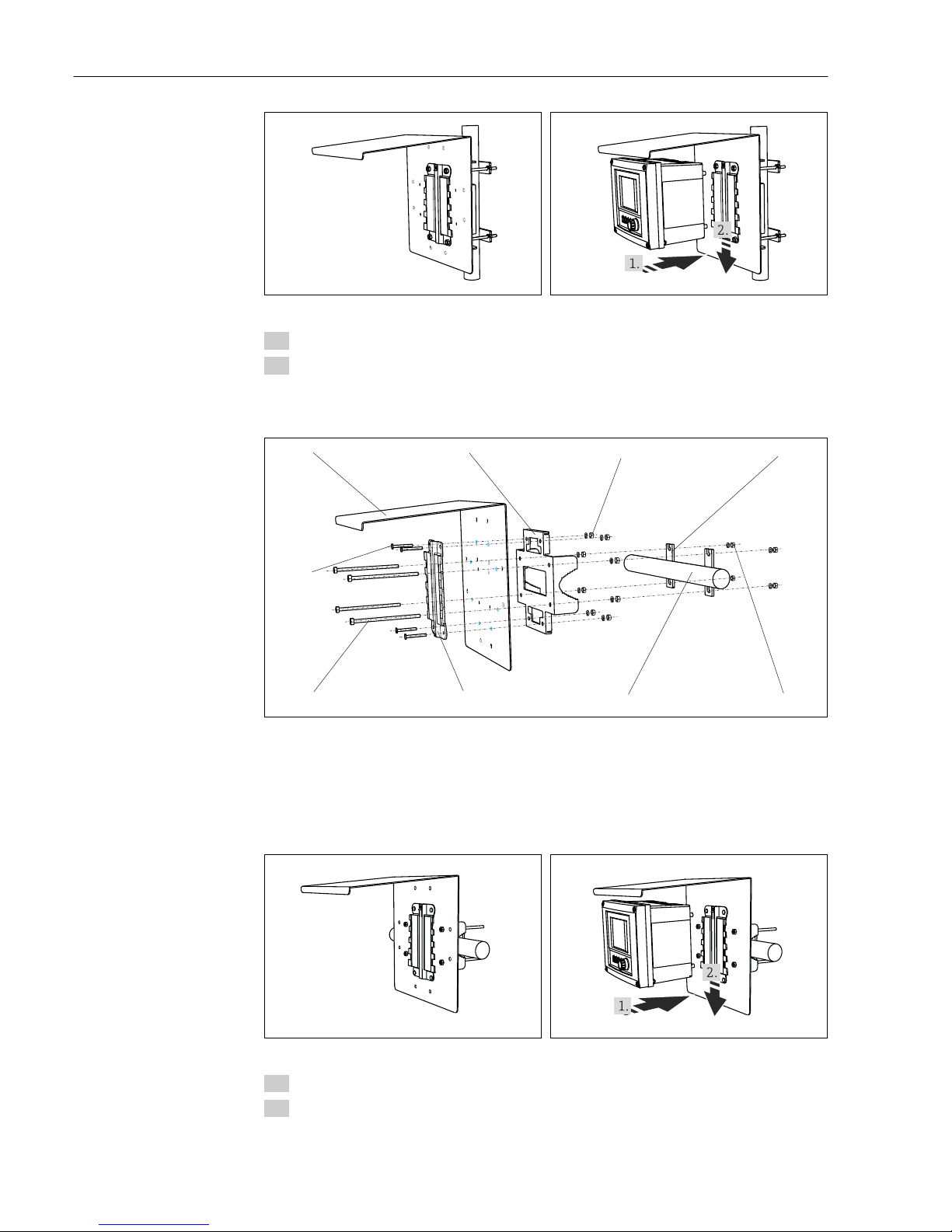
5.2.2 Rail mounting
1 2
3
4
56
7
8
9
A0012668
12 Rail mounting
1 Weather protection cover (optional) 6 Pipe or railing (circular/square)
2 Post mounting plate (post mounting kit) 7 Mounting plate
3 Spring washers, nuts (post mounting kit) 8 Threaded rods (post mounting kit)
4 Pipe clamps (post mounting kit) 9 Screws (post mounting kit)
5 Spring washers, nuts (post mounting kit)
A0025886
13 Rail mounting
A0027803
14 Attach the device and click it into place
1. Bring the device to the mounting plate.
2. Slide the device downwards in the guide on the mounting rail until it clicks into place.
Liquiline CM442/CM444/CM448 Installation
Endress+Hauser 17
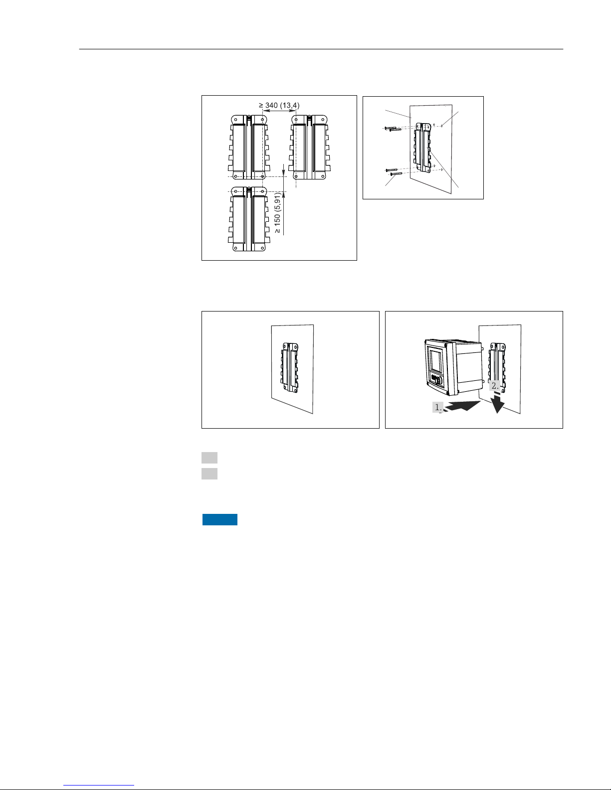
5.2.3 Wall mounting
A0012686
15 Mounting distance in mm (inch)
1
3
4
2
16 Wall mounting
1 Wall
2
4 drill holes
1)
3 Mounting plate
4 Screws Ø 6 mm (not part of scope of supply)
1)
The size of the drill holes depends on the wall plugs used. The wall plugs and screws must be provided by the
customer.
A0027799
17 Wall mounting
A0027797
18 Attach the device and click it into place
1. Bring the device to the mounting plate.
2. Slide the device downwards in the guide on the mounting rail until it clicks into place.
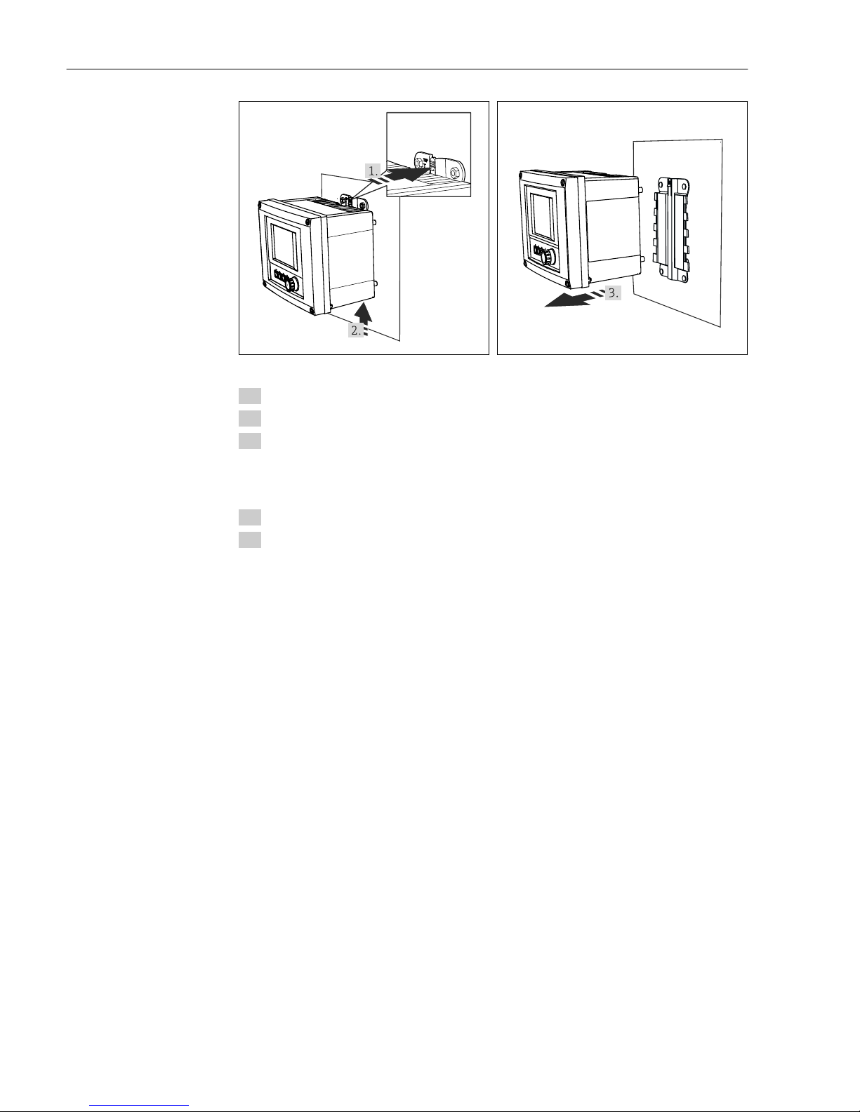
5.2.4 Disassembly (for conversion, cleaning etc.)
NOTICE
The device can be damaged if dropped
‣
When pushing the housing out of the holder, secure the housing in such a way that you
do not drop it. If possible, ask a second person to help you.
Installation Liquiline CM442/CM444/CM448
18 Endress+Hauser
A0025890
19 Disassembling
A0025891
20 Disassembling
1. Hold down the catch.
2. Push up the device to remove it from the holder.
3. Remove the device towards the front.
5.3 Post-installation check
1. After installation, check the transmitter for damage.
2. Check whether the transmitter is protected against moisture and direct sunlight (e.g.
by the weather protection cover).
Liquiline CM442/CM444/CM448 Electrical connection
Endress+Hauser 19
6 Electrical connection
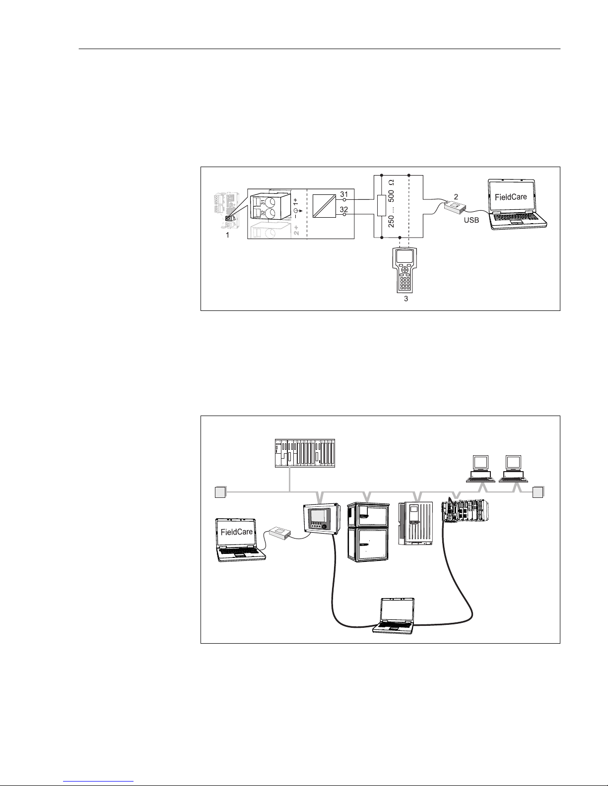
6.1 Connection conditions
6.1.1 Via HART (e.g. using HART modem and FieldCare)
A0028995
21 HART using modem
1 Device module Base L, H or E: current output 1 with HART
2
HART modem for connection to PC, e.g. Commubox FXA191 (RS232) or FXA195 1) (USB)
3 HART handheld terminal
1)
Switch position "on" (substitutes the resistor)
6.1.2 Via PROFIBUS DP
FXA291
Master class 1
(PLC, DCS)
T T
Ethernet
PROFIBUS DP
(RS485)
Master class 2 (FieldCare, PDM)
FieldCare /
Webbrowser
A0028991
22 PROFIBUS DP
T Terminating resistor
Electrical connection Liquiline CM442/CM444/CM448
20 Endress+Hauser
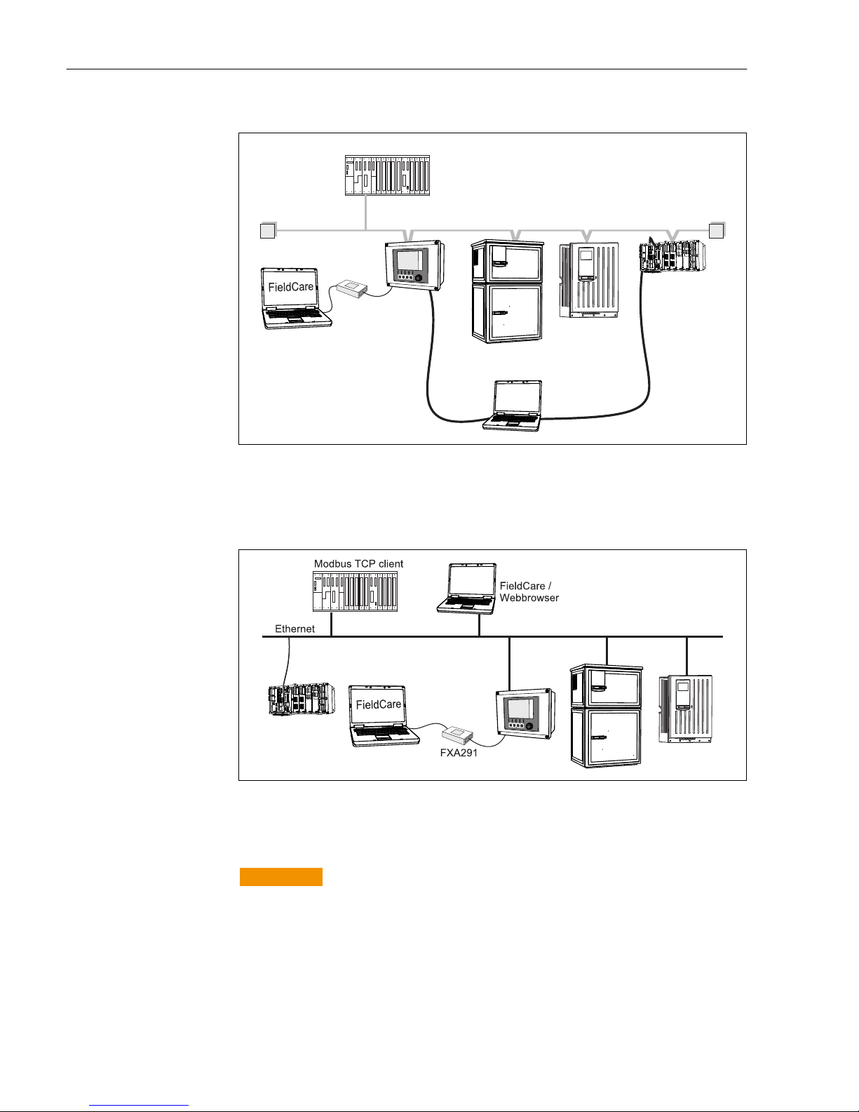
6.1.3 Via Modbus RS485
FXA291
Modbus Master / Gateway
T T
Ethernet
Modbus RS485
(RTU, ASCII)
FieldCare /
Webbrowser
A0028993
23 Modbus RS485
T Terminating resistor
6.1.4 Via Ethernet/Web server/Modbus TCP/EtherNet/IP
A0028994
24 Modbus TCP and/or EtherNet/IP
6.2 Connecting the measuring device
L
WARNING
Device is live
Incorrect connection may result in injury or death
‣
The electrical connection may be performed only by an electrical technician.
‣
The electrical technician must have read and understood these Operating Instructions
and must follow the instructions contained therein.
‣
Prior to commencing connection work, ensure that no voltage is present on any cable.
Liquiline CM442/CM444/CM448 Electrical connection
Endress+Hauser 21
NOTICE
The device does not have a power switch
‣
The customer must provide a protected circuit breaker in the vicinity of the device.
‣
The circuit breaker must be a switch or power switch, and you must label it as the
circuit breaker for the device.
‣
At the supply point, the power supply must be isolated from dangerous live cables by
double or reinforced insulation in the case of devices with a 24 V supply voltage.
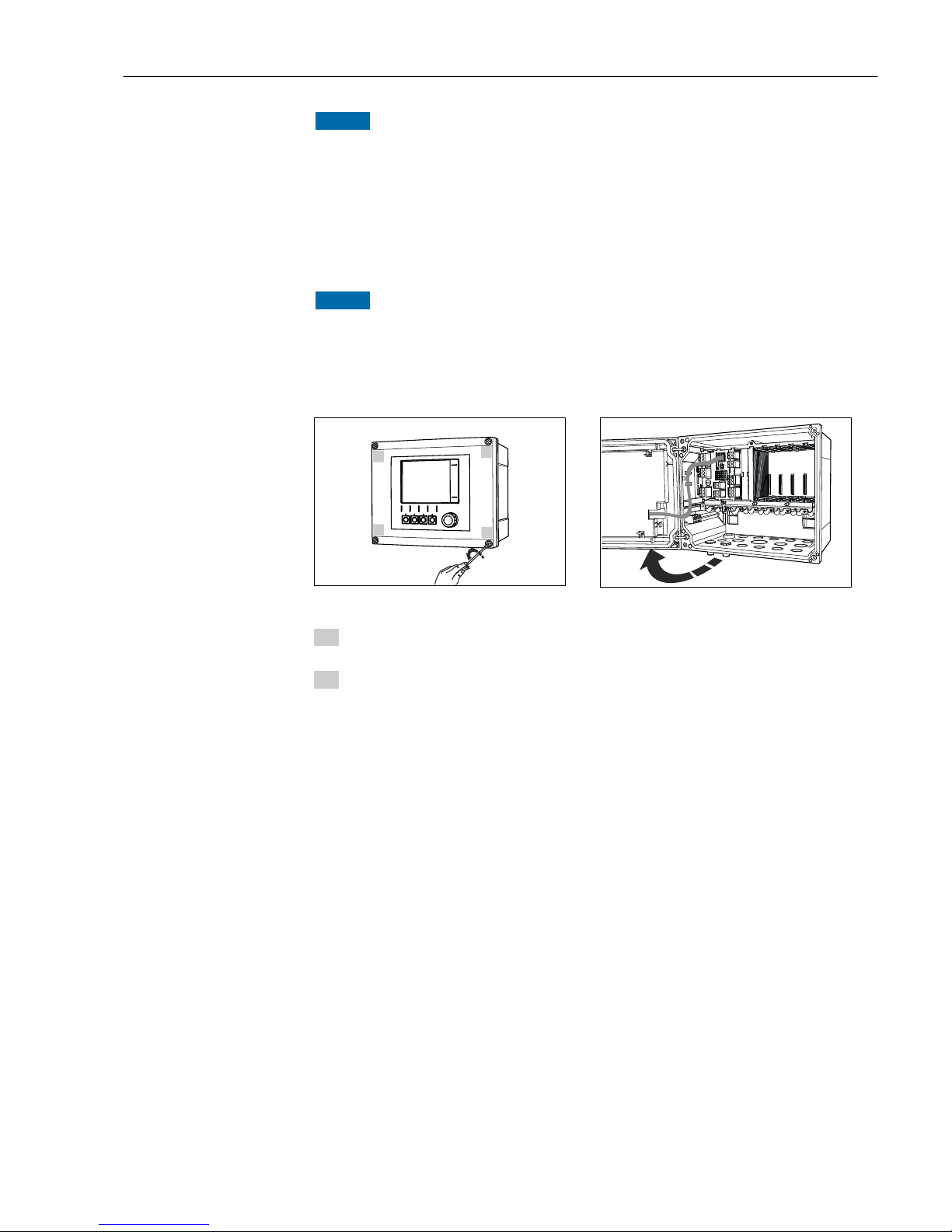
6.2.1 Open the housing
NOTICE
Pointed or sharp tools
If unsuitable tools are used, they can scratch the housing or damage the seal, and thus
have a negative impact on the leak-tightness of the housing.
‣
Do not use any sharp or pointed objects, such as a knife, to open the housing.
‣
Only use a suitable Phillips screwdriver.
1.
2.
3.
4.
25 Releasing housing screws in a diagonally
opposite sequence with Phillips screwdriver
£180°
26 Opening display cover, max. opening angle
180˚ (depends on installation position)
1. Release the housing screws step by step. Start with any screw and then release the
screw diagonally opposite etc.
2. When closing the housing, also tighten the screws step-by-step in a diagonally
opposite sequence.
Electrical connection Liquiline CM442/CM444/CM448
22 Endress+Hauser
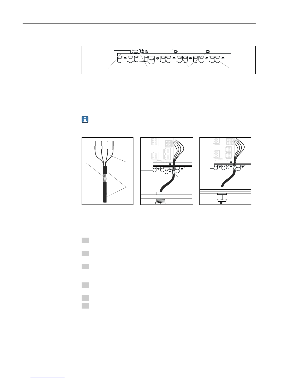
6.2.2 Cable mounting rail
1 32 4
A0025171
27 Cable mounting rail and associated function
1 Cable mounting rail 3 Additional threaded bolts for ground connections
2 Threaded bolt (protective ground connection,
central grounding point)
4 Cable clamps (fixing and grounding the sensor
cables)
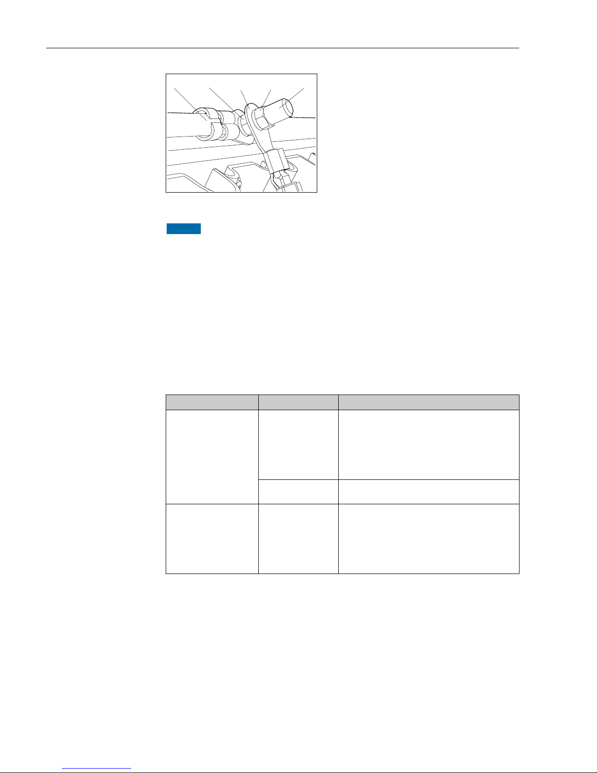
6.2.3 Connecting the cable shield
If possible, only use terminated genuine cables. The sensor, fieldbus and ethernet
cables must be shielded.
Cable sample (does not necessarily correspond to the genuine cable supplied)
1
2
3
28 Terminated cable
1 Outer shield (exposed)
2 Cable cores with ferrules
3 Cable sheath (insulation)
4
29 Inserting the cable
4 Grounding clip
30 Tighten screw (2 Nm)
Cable shield is grounded using the
grounding clamp
1)
1) Please note the instructions in the "Guaranteeing the degree of protection" section (→ 36)
1. Release a suitable cable gland on the underside of the housing and remove the
dummy plug from the entry.
2. Making sure the gland is facing the right direction, thread the gland onto the cable
end and pull the cable through the entry and into the housing.
3. Route the cable in the housing in such a way that the exposed cable shield fits into
one of the cable clamps and the cable cores can be easily routed as far as the
connection plug on the electronics module.
4. Screw on the cable clamp and clamp the cable in place. Then tighten the screw of the
cable clamp.
5. Connect the cable cores as per the wiring diagram.
6. Lastly, tighten the cable gland from the outside.
Liquiline CM442/CM444/CM448 Electrical connection
Endress+Hauser 23
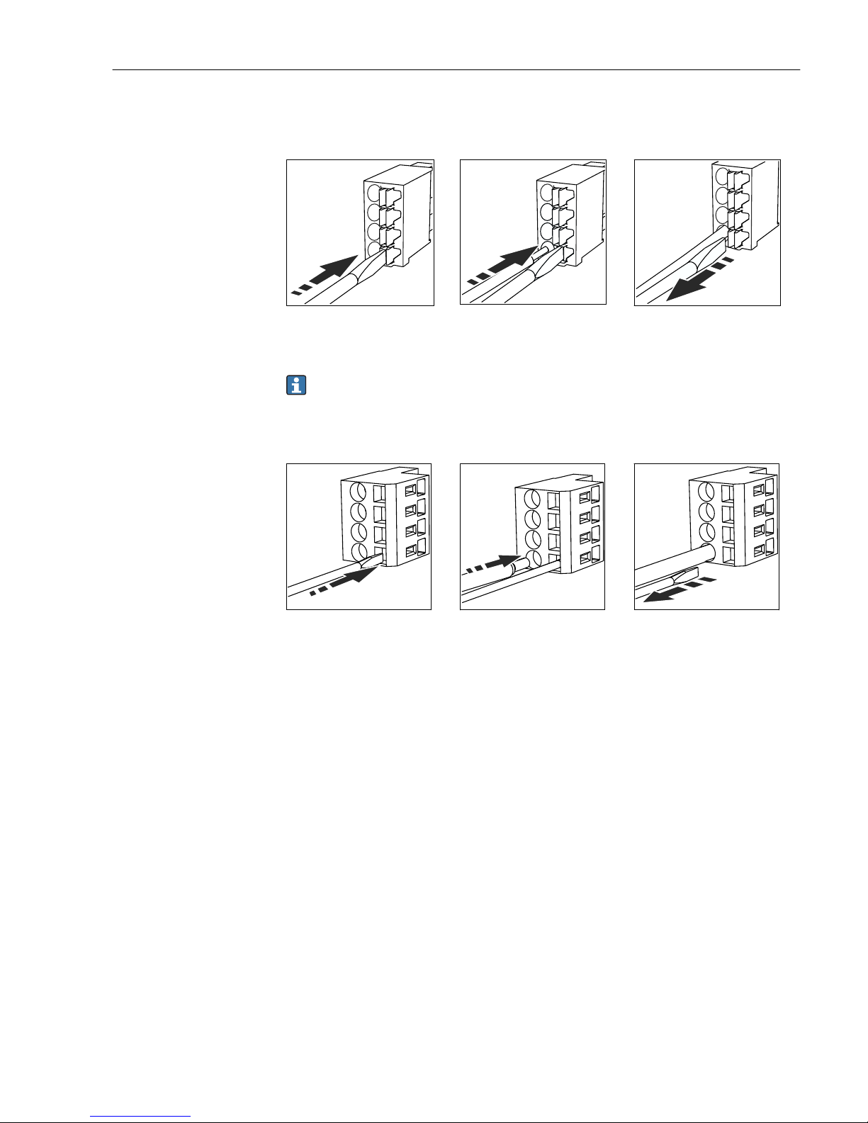
6.2.4 Cable terminals
Plug-in terminals for Memosens and PROFIBUS/RS485 connections
Press the screwdriver against the clip
(opens the terminal)
Insert the cable until the limit stop
Remove the screwdriver (closes the
terminal)
After connection, make sure that every cable end is securely in place. Terminated
cable ends, in particular, tend to come loose easily if they have not been correctly
inserted as far as the limit stop.
All other plug-in terminals
Press the screwdriver against the clip
(opens the terminal)
Insert the cable until the limit stop Remove the screwdriver (closes the
terminal)
Electrical connection Liquiline CM442/CM444/CM448
24 Endress+Hauser
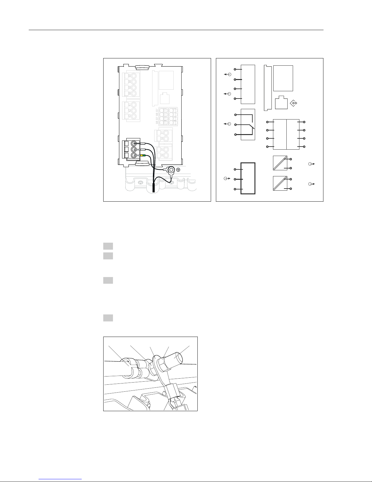
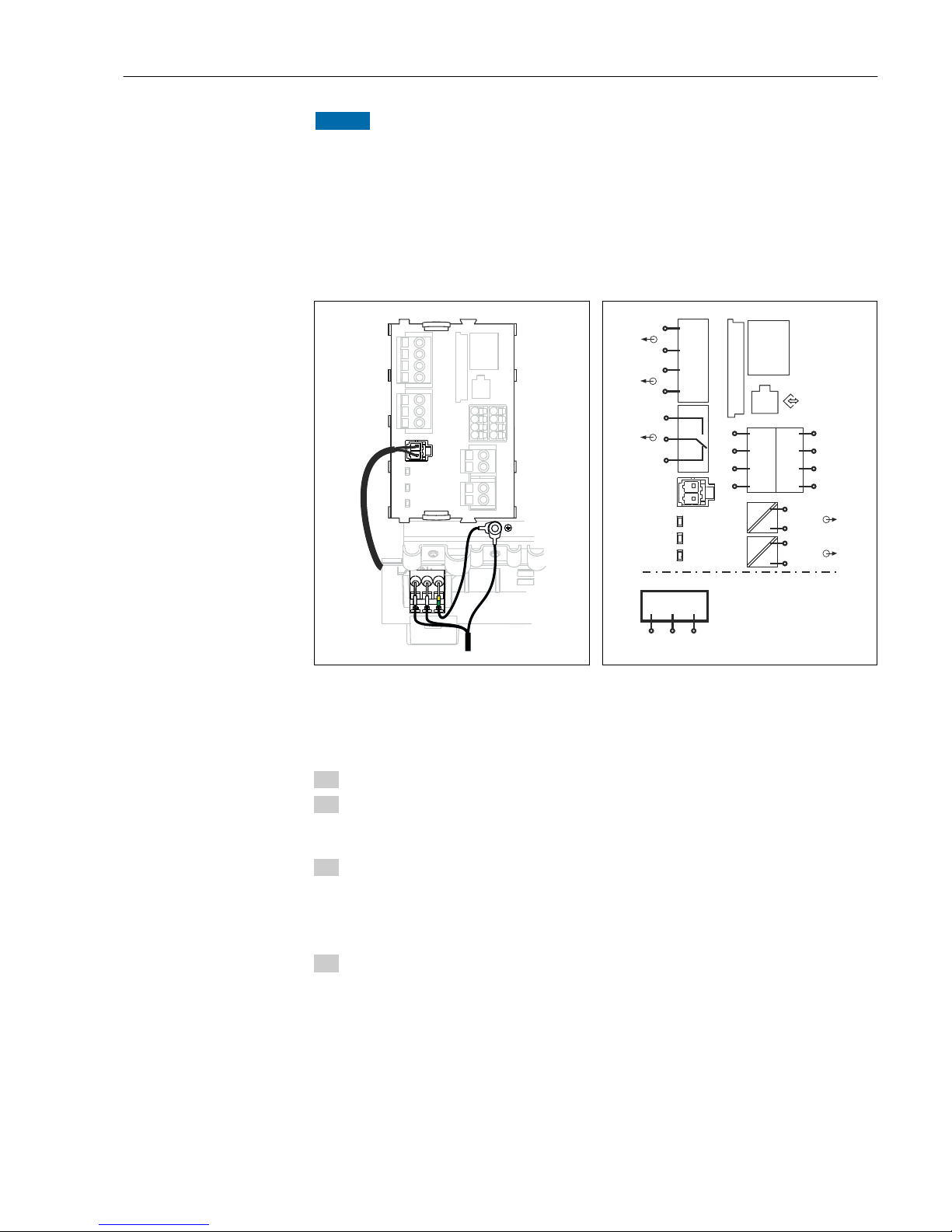
6.2.5 Connecting the supply voltage for the CM442
N/- L/+
43
42
41
86
85
86
85
98
97
88
87
32
31
32
31
PE
A0015825
31 Connecting power supply on the BASE-H or -L
H Power unit 100 to 230 VAC
L Power unit 24 VAC or 24 VDC
85
85
86
86
SD
Display
Sensor supply
+
+
–
Service
PK
GY
PK
GYGY
1
2
–
L
N
*
Power
L / +
N / –
PE
87
88
97
98
1
2
Sensor
BN
WH
GN
YE
BN
WH
GN
YE
87
88
97
98
+
–
A
B
+
–
A
B
41
43
42
Alarm
31
31
32
32
0/4 ... 20 mA
+
+
–
1
2
–
HART
A0012404
32 Overall wiring diagram for BASE-H or -L
Connecting the supply voltage
1. Route the power supply cable into the housing through the suitable cable entry.
2. Step 2 applies only to the 100 to 230 V AC power unit.
Connect the protective ground of the power unit to the threaded bolt specially
provided on the cable mounting rail.
3. Protective ground or grounding provided by the customer (absolutely essential for
24 V power unit, additionally recommended for 100 to 230 V AC power unit):
You must provide a ground cable (min. 0.75 mm2 (corresponding to 18 AWG)). Guide
the ground cable also through the cable entry and connect it to the threaded bolt on
the cable mounting rail.
4. Connect the cable cores L and N (100 to 230 V AC) or + and ‐ (24 V DC) to the plugin terminals on the power unit in accordance with the wiring diagram.
1 2
3
4
5
33 Protective ground or grounding
connection
1 Protective ground of power unit
2 Serrated washer and nut
3 Protective ground / ground cable, provided by the
customer (min. 0.75 mm2 ( 18 AWG))
4 Serrated washer and nut
5 Mounting bolts
Liquiline CM442/CM444/CM448 Electrical connection
Endress+Hauser 25
NOTICE
Protective ground/ground cable with end sleeve or open cable lug
The cable can become loose. Loss of the protective function.
‣
To connect the protective ground or ground cable to the threaded bolt, only use a cable
with a closed cable lug as per DIN 46211, 46225, form A.
‣
Never connect the protective ground or ground cable to the threaded bolt with an end
sleeve or an open cable lug!
6.2.6 Connecting the supply voltage for the CM444 and the CM448
L+ N- PE
A
43 42 41
86 85 86 85
98 97 88 87
32 31
32 31
B
A0015872
34 Power supply connection on the BASE-E
A Internal power supply cable
B Extension power unit
85
85
86
86
41
43
42
L/+
N/–
*
Power
87
88
97
98
31
31
32
32
SD
Display
1
2
Sensor
0/4 ... 20 mA
Sensor supply
+
+
–
+
+
–
1
2
Service
PK
GY
PK
GY
1
2
–
L/+
N/–
PE
BN
WH
GN
YE
BN
WH
GN
YE
87
88
97
98
+
–
A
B
+
–
A
B
–
Alarm
HART
Power
(internal)
B
A0015873
35 Overall wiring diagram BASE-E and
extension power unit (B)
Connecting the supply voltage
1. Route the power supply cable into the housing through the suitable cable entry.
2. Step 2 applies only to the 100 to 230 V AC power unit.
Connect the protective ground of the power unit to the threaded bolt specially
provided on the cable mounting rail.
3. Protective ground or grounding provided by the customer (absolutely essential for
24 V power unit, additionally recommended for 100 to 230 V AC power unit):
You must provide a ground cable (min. 0.75 mm2 (corresponding to 18 AWG)). Guide
the ground cable also through the cable entry and connect it to the threaded bolt on
the cable mounting rail.
4. Connect the cable cores L and N (100 to 230 V AC) or + and ‐ (24 V DC) to the plugin terminals on the power unit in accordance with the wiring diagram.
Electrical connection Liquiline CM442/CM444/CM448
26 Endress+Hauser
1 2
3
4
5
36 Protective ground or grounding
connection
1 Protective ground of power unit
2 Serrated washer and nut
3 Protective ground / ground cable, provided by the
customer (min. 0.75 mm2 ( 18 AWG))
4 Serrated washer and nut
5 Mounting bolts
NOTICE
Protective ground/ground cable with end sleeve or open cable lug
The cable can become loose. Loss of the protective function.
‣
To connect the protective ground or ground cable to the threaded bolt, only use a cable
with a closed cable lug as per DIN 46211, 46225, form A.
‣
Never connect the protective ground or ground cable to the threaded bolt with an end
sleeve or an open cable lug!
6.3 Connecting the sensors
6.3.1 Sensor types with Memosens protocol
Sensors with Memosens protocol
Sensor types Sensor cable Sensors
Digital sensors without
additional internal power
supply
With plug-in
connection and
inductive signal
transmission
• pH sensors
• ORP sensors
• Combined sensors
• Oxygen sensors (amperometric and optical)
• Conductivity sensors with conductive measurement of
conductivity
• Chlorine sensors
Fixed cable Conductivity sensors with inductive measurement of
conductivity
Digital sensors with
additional internal power
supply
Fixed cable • Turbidity sensors
• Sensors for interface measurement
• Sensors for measuring the spectral absorption
coefficient (SAC)
• Nitrate sensors
• Optical oxygen sensors
• Ion-sensitive sensors
The following rule applies if connecting CUS71D sensors:
• CM442
– Only one CUS71D is possible; an additional sensor is not permitted.
– The second sensor input may also not be used for another type of sensor.
• CM444
No restrictions. All the sensor inputs can be used as required.
• CM448
– If a CUS71D is connected, the number of sensor inputs that can be used is limited to a
maximum of 4.
– Of these, all 4 inputs can be used for CUS71D sensors.
– Every combination of CUS71D and other sensors is possible, provided that the total
number of connected sensors does not exceed 4.
Liquiline CM442/CM444/CM448 Electrical connection
Endress+Hauser 27
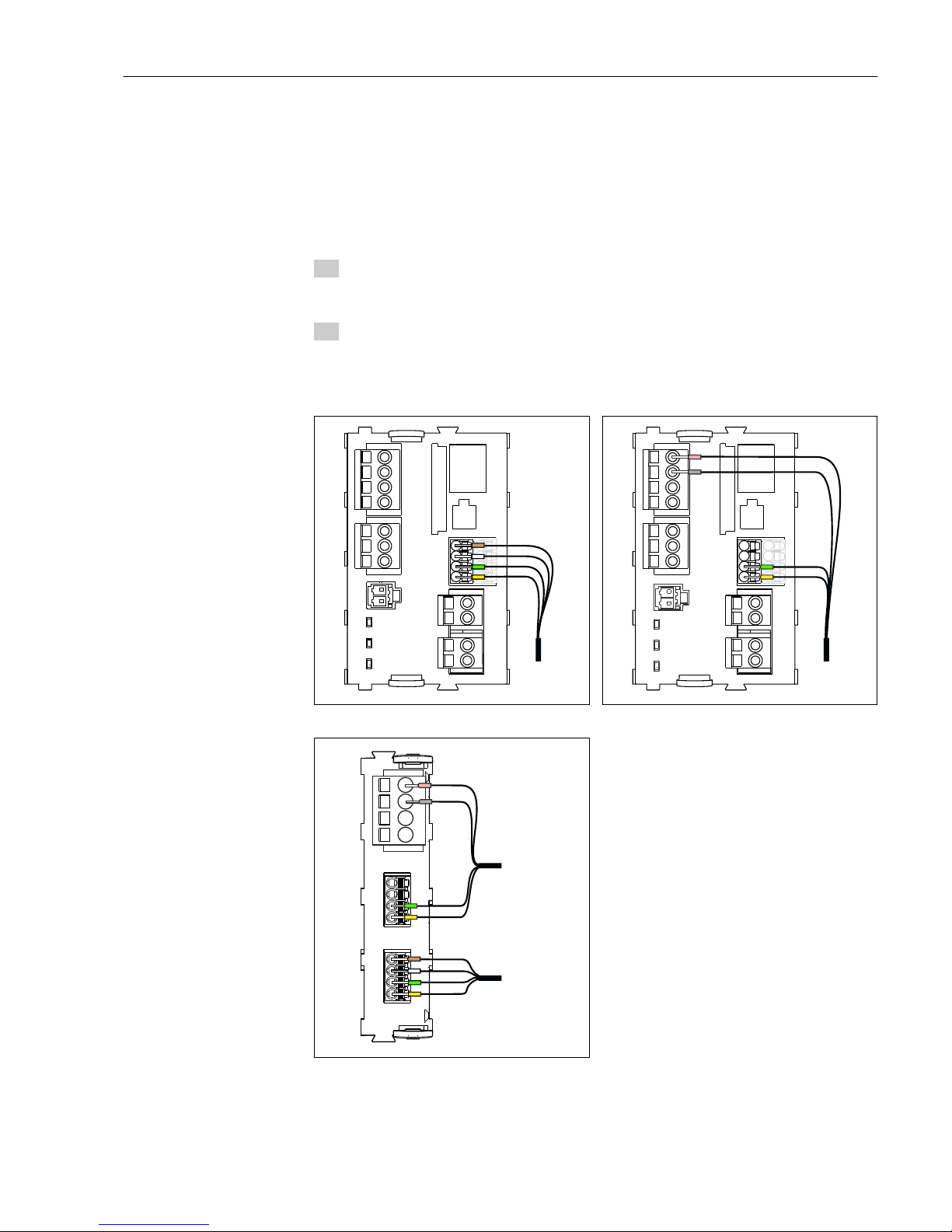
6.3.2 Connecting the sensors
Types of connection
• Direct connection of sensor cable to terminal connector of sensor module 2DS or of base
module L, H or E (→ 37 ff.)
• Optional: Sensor cable plug connected to the M12 sensor socket on the underside of the
device
With this type of connection, the device is already wired at the factory (→ 40).
1. Sensor cable connected directly
Connect the sensor cable to the Memosensterminal connector of the sensor module
2DS or of base module L, H or E.
2. When connecting via M12 connector
Connect the sensor connector to an M12 sensor socket which has been previously
installed or is supplied on delivery.
Sensor cable connected directly
43 42 41
86 85 86 85
98 97 88 87
32 31
32 31
BN
WH
GN
YE
Sensor
A0023038
37 sensors without additional supply voltage
43 42 41
86 85 86 85
98 97 88 87
32 31
32 31
PK
GY
GN
YE
Sensor
A0023039
38 sensors with additional supply voltage
85 86
85
2DS
1
2
86
97 88 8798
97 88 8798
Sensor 1
Sensor 2
PK
GY
GN
YE
BN
WH
GN
YE
Sensor
Sensor
A0016197
39 sensors with and without additional supply
voltage on 2DS sensor module
Electrical connection Liquiline CM442/CM444/CM448
28 Endress+Hauser
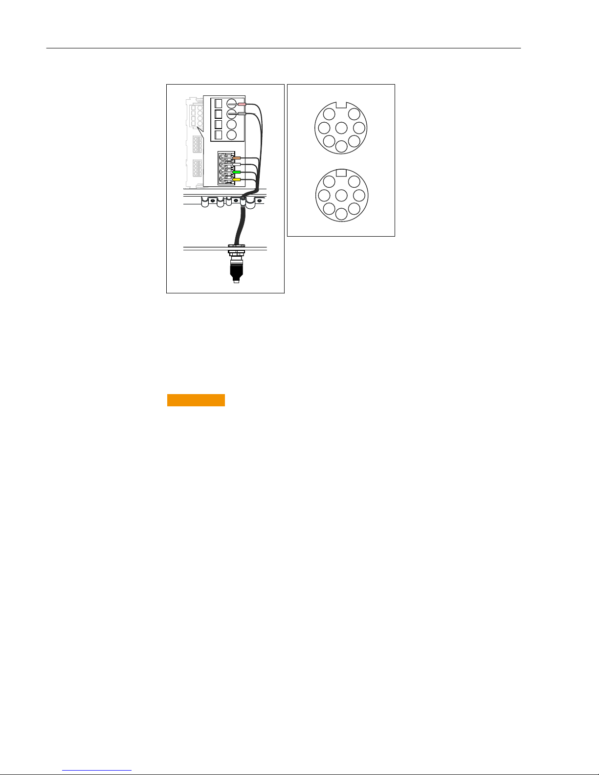
connection via M12 connection
85 86
85
1
2
86
97 88 8798
Sensor 1
PK
GY
GN
YE
BN
WH
1
A0018019
40 M12 plug-in connection (e.g.
at sensor module)
1 Sensor cable with M12
connector
6
4
1
NC
2
3
5
7
4
6
2
NC
1
7
5
3
A0018021
41 M12 assignment Top:
socket Bottom: connector
(top view in each case)
1 PK (24 V)
2 GY (Ground 24 V)
3 BN (3 V)
4 WH (Ground 3 V)
5 GN (Memosens)
6 YE (Memosens)
7,NCNot connected
Device versions with a pre-installed
M12 socket are ready-wired upon
delivery. Install an M12 socket, which
is available as an accessory, in a
suitable cable gland opening in the
base of the housing, and connect the
cables to the Memosens terminals of
the sensor or base module as per the
wiring diagram.
Connecting the sensor
‣ Plug the connector of the sensor
cable (item 1) directly into the M12
socket.
Please note the following for these
device versions:
• The internal device wiring is always
the same regardless of what kind of
sensor you connect to the M12
socket (plug&play).
• The signal and power supply cables
are assigned in the sensor plug-in
head in such a way that the PK and
GY power supply cables are either
used (e.g. optical sensors) or not
(e.g. pH or ORP sensors).
6.4 Connecting additional inputs, outputs or relays
L
WARNING
Module not covered
No shock protection. Danger of electric shock!
‣
If you are modifying or extending your hardware, always fill the slots from left to right.
Do not leave any gaps.
‣
If not all slots are occupied, always insert a dummy or end cover into the slot to the
right of the last module. (→ 2, 9)This ensures the that unit is shock-protected.
‣
If not all slots are occupied, always insert a dummy or end cover into the slot to the
right of the last module. This ensures the that unit is shock-protected.
‣
Always ensure shock protection is guaranteed particularly in the case of relay modules
(2R, 4R, AOR).
Liquiline CM442/CM444/CM448 Electrical connection
Endress+Hauser 29
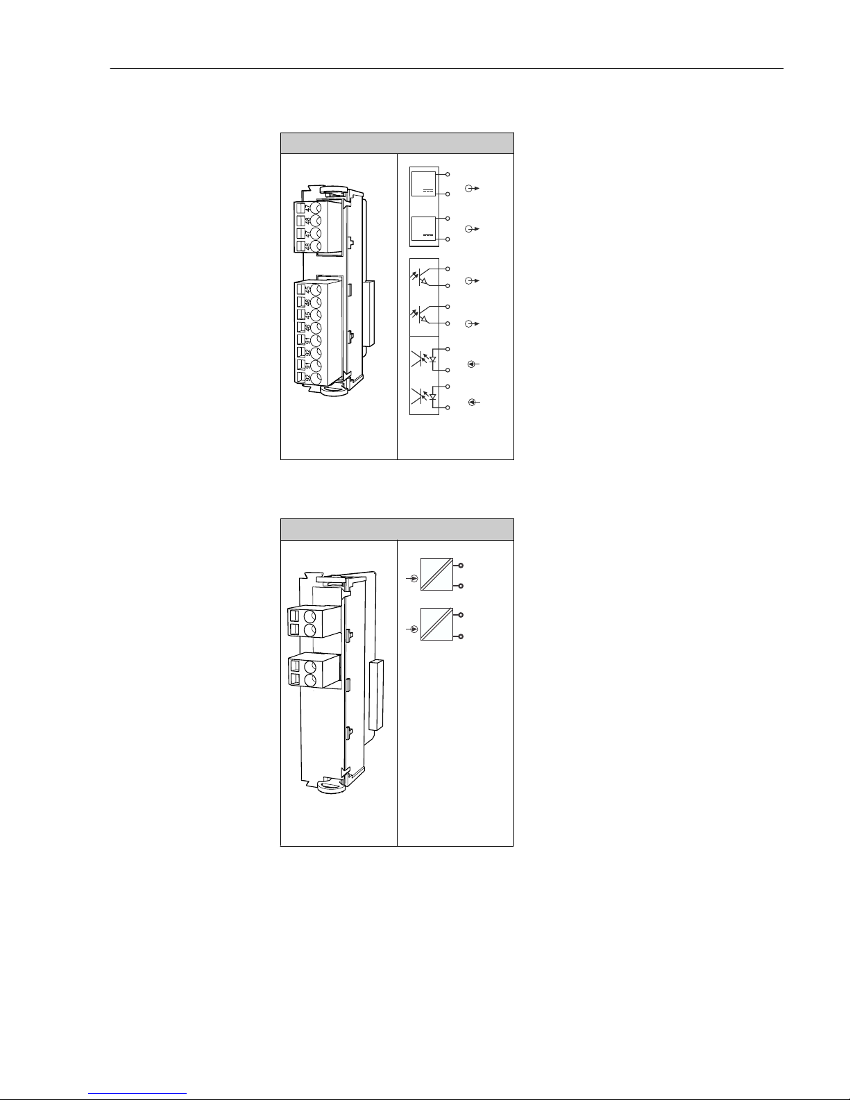
6.4.1 Digital inputs and outputs
DIO module
42 Module
47
47
48
48
+
+
–
1
2
–
1
2
1
2
+
–
–
+
+
–
+
–
45
46
45
46
91
92
91
92
43 Wiring
diagram
6.4.2 Current inputs
Module 2AI
2324
2324
44 Module
23
23
24
24
0/4 ... 20 mA
+
+
–
1
2
–
45 Wiring
diagram
Electrical connection Liquiline CM442/CM444/CM448
30 Endress+Hauser
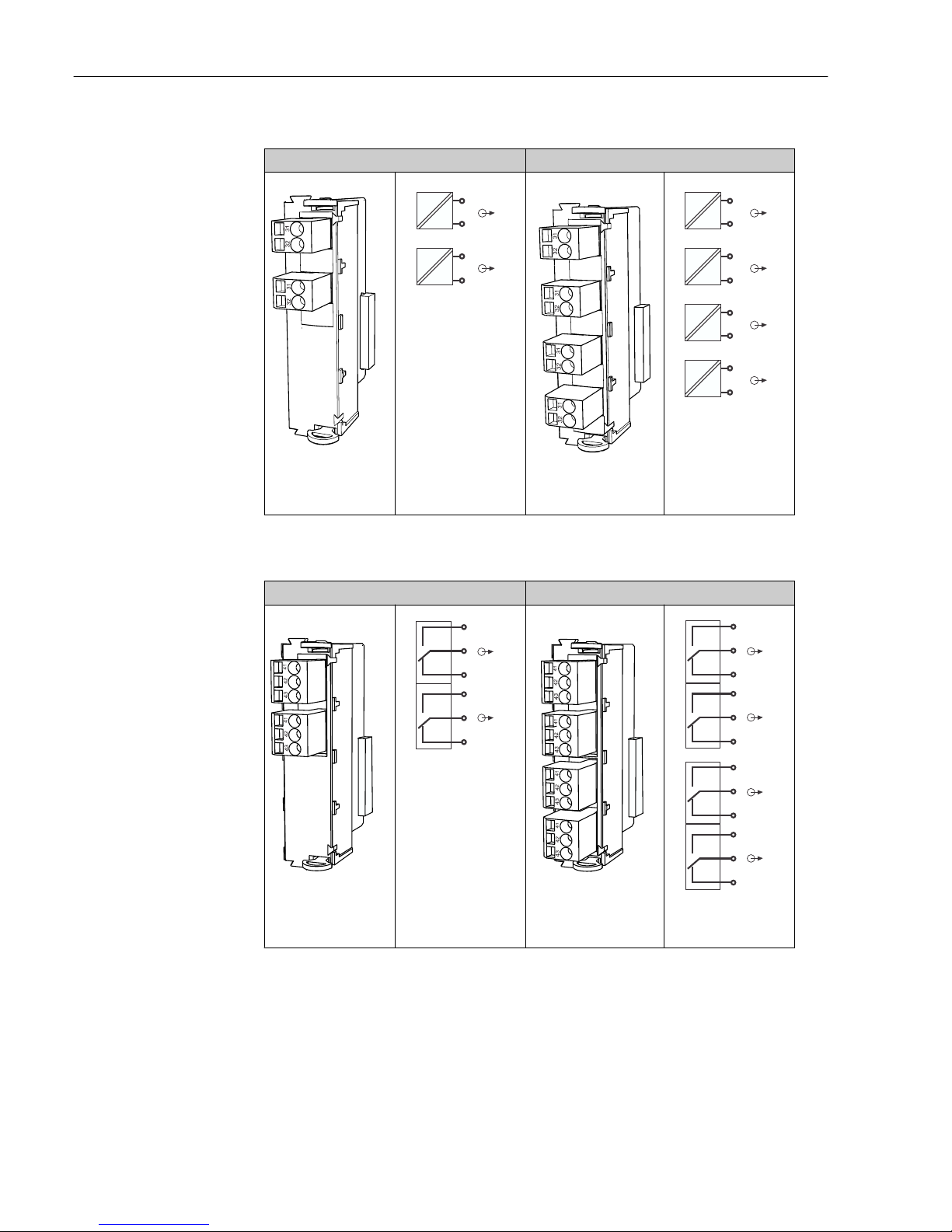
6.4.3 Current outputs
2AO 4AO
46 Module
31
31
32
32
0/4 ... 20 mA
+
+
–
1
2
–
47 Wiring
diagram
48 Module
31
31
32
32
0/4 ... 20 mA
+
+
–
1
2
–
31
31
32
32
0/4 ... 20 mA
+
+
–
3
4
–
49 Wiring
diagram
6.4.4 Relay
Module 2R Module 4R
50 Module
41
43
42
Relay 1
41
43
42
Relay 2
51 Wiring
diagram
52 Module
41
43
42
Relay 3
41
43
42
Relay 4
41
43
42
Relay 1
41
43
42
Relay 2
53 Wiring
diagram
 Loading...