

Page 1
TI393F/00/en
Technical Information
Liquicap T FMI21
Capacitive level measurement
Two-rod probe for continuous measurement in liquids
Application
The Liquicap T sensor is used in conductive liquids
(as of 30 µS/cm) for continuous level measurement and
is preconfigured from factory 0 %...100 % to probe length
ordered.
As of a conductivity of 30 µS/cm, the measurement is
independent of the dc-value (dielectric constant) of the
liquid. It can also be deployed in Ex area, Zone 2.
The Liquicap T is particularly suited to the following
applications:
• Small measuring ranges (as of 150 mm)
• Cistern measurements
• Aggressive liquids such as acids and alkalis
• Independent of the tank material (plastic, stainless
steel or concrete) or the tank shape
Used in conjunction with the Fieldgate FXA320 (remote
measured value interrogation using Internet technology),
Liquicap T is an ideal solution for inventorying material
and optimising logistics (inventory control).
Your benefits
• Safe function regardless of tank geometry thanks to
probe design
• No calibration necessary (preconfigured from factory
0 %...100 % to probe length ordered)
• High quality, non-corrosive materials (carbon fibre,
stainless steel) for use in aggressive liquids and liquids
which present a hazard to water (WHG-approved
(German Water Resources Law))
• No moving parts in tank - long operating life dependable function without wear
• Cost-effective solution for continuous measurement of
levels in conductive liquids
• Optimised storage by simply shortening the probe rods
on site (probe shortening set)
Page 2

Liquicap T FMI21
2
Endress+Hauser
Table of contents
Function and system design. . . . . . . . . . . . . . . . . . . . . 3
Measuring principle . . . . . . . . . . . . . . . . . . . . . . . . . . . . . . . . . . . 3
Measuring system . . . . . . . . . . . . . . . . . . . . . . . . . . . . . . . . . . . . . 3
Operating medium . . . . . . . . . . . . . . . . . . . . . . . . . . . . . . . . . . . 4
Applications . . . . . . . . . . . . . . . . . . . . . . . . . . . . . . . . . . . . . . . . . 4
Input . . . . . . . . . . . . . . . . . . . . . . . . . . . . . . . . . . . . . . 5
Measured variable . . . . . . . . . . . . . . . . . . . . . . . . . . . . . . . . . . . . 5
Measuring range . . . . . . . . . . . . . . . . . . . . . . . . . . . . . . . . . . . . . . 5
Input signal . . . . . . . . . . . . . . . . . . . . . . . . . . . . . . . . . . . . . . . . . 5
Output . . . . . . . . . . . . . . . . . . . . . . . . . . . . . . . . . . . . . 5
Electronic insert FEI20 (4...20 mA) . . . . . . . . . . . . . . . . . . . . . . . . 5
Power supply . . . . . . . . . . . . . . . . . . . . . . . . . . . . . . . . 6
Electrical connection (wiring diagram) . . . . . . . . . . . . . . . . . . . . . 6
Transmitter power supply units from Endress+Hauser . . . . . . . . . . 6
Supply voltage (FEI20) . . . . . . . . . . . . . . . . . . . . . . . . . . . . . . . . . 6
Power consumption . . . . . . . . . . . . . . . . . . . . . . . . . . . . . . . . . . . 6
Current consumption . . . . . . . . . . . . . . . . . . . . . . . . . . . . . . . . . . 6
Cable entries . . . . . . . . . . . . . . . . . . . . . . . . . . . . . . . . . . . . . . . . 6
Cable specifications . . . . . . . . . . . . . . . . . . . . . . . . . . . . . . . . . . . 7
Performance characteristics
with installed electronic insert . . . . . . . . . . . . . . . . . . 7
Reference operating conditions . . . . . . . . . . . . . . . . . . . . . . . . . . . 7
Maximum measured error . . . . . . . . . . . . . . . . . . . . . . . . . . . . . . 7
Repeatability . . . . . . . . . . . . . . . . . . . . . . . . . . . . . . . . . . . . . . . . . 7
Start-up settling time . . . . . . . . . . . . . . . . . . . . . . . . . . . . . . . . . . 7
Influence of ambient temperature . . . . . . . . . . . . . . . . . . . . . . . . . 7
Integration time. . . . . . . . . . . . . . . . . . . . . . . . . . . . . . . . . . . . . . 7
Factory calibration . . . . . . . . . . . . . . . . . . . . . . . . . . . . . . . . . . . . 7
Installation. . . . . . . . . . . . . . . . . . . . . . . . . . . . . . . . . . 8
Installation instructions . . . . . . . . . . . . . . . . . . . . . . . . . . . . . . . . . 8
Environment . . . . . . . . . . . . . . . . . . . . . . . . . . . . . . . . 8
Ambient temperature range . . . . . . . . . . . . . . . . . . . . . . . . . . . . . 8
Ambient temperature limits . . . . . . . . . . . . . . . . . . . . . . . . . . . . . 8
Storage temperature . . . . . . . . . . . . . . . . . . . . . . . . . . . . . . . . . . . 8
Climate class . . . . . . . . . . . . . . . . . . . . . . . . . . . . . . . . . . . . . . . . 8
Degree of protection . . . . . . . . . . . . . . . . . . . . . . . . . . . . . . . . . . . 8
Shock resistance . . . . . . . . . . . . . . . . . . . . . . . . . . . . . . . . . . . . . . 8
Vibration resistance (with min. rod length 150 mm) . . . . . . . . . . . 8
Electromagnetic compatibility . . . . . . . . . . . . . . . . . . . . . . . . . . . . 8
Process . . . . . . . . . . . . . . . . . . . . . . . . . . . . . . . . . . . . 9
Environment . . . . . . . . . . . . . . . . . . . . . . . . . . . . . . . . . . . . . . . . 9
Conductivity of medium . . . . . . . . . . . . . . . . . . . . . . . . . . . . . . . . 9
Process pressure . . . . . . . . . . . . . . . . . . . . . . . . . . . . . . . . . . . . . 9
Mechanical construction . . . . . . . . . . . . . . . . . . . . . . 10
Design, dimensions . . . . . . . . . . . . . . . . . . . . . . . . . . . . . . . . . . 10
Probe shortening set . . . . . . . . . . . . . . . . . . . . . . . . . . . . . . . . . 10
Weight . . . . . . . . . . . . . . . . . . . . . . . . . . . . . . . . . . . . . . . . . . . 11
Material . . . . . . . . . . . . . . . . . . . . . . . . . . . . . . . . . . . . . . . . . . . 11
Fitted electrodes . . . . . . . . . . . . . . . . . . . . . . . . . . . . . . . . . . . . 11
Human interface . . . . . . . . . . . . . . . . . . . . . . . . . . . . 12
Operating elements . . . . . . . . . . . . . . . . . . . . . . . . . . . . . . . . . . 12
Display elements . . . . . . . . . . . . . . . . . . . . . . . . . . . . . . . . . . . . 12
Certificates and approvals . . . . . . . . . . . . . . . . . . . . . 13
CE mark . . . . . . . . . . . . . . . . . . . . . . . . . . . . . . . . . . . . . . . . . . 13
Overfill protection . . . . . . . . . . . . . . . . . . . . . . . . . . . . . . . . . . . 13
Other standards and guidelines . . . . . . . . . . . . . . . . . . . . . . . . . . 13
Ex approval . . . . . . . . . . . . . . . . . . . . . . . . . . . . . . . . . . . . . . . . 13
Type of protection . . . . . . . . . . . . . . . . . . . . . . . . . . . . . . . . . . . 13
Ordering information. . . . . . . . . . . . . . . . . . . . . . . . . 14
Liquicap T FMI21 . . . . . . . . . . . . . . . . . . . . . . . . . . . . . . . . . . . 14
Accessories . . . . . . . . . . . . . . . . . . . . . . . . . . . . . . . . 14
Liquicap T . . . . . . . . . . . . . . . . . . . . . . . . . . . . . . . . . . . . . . . . 14
Spare parts . . . . . . . . . . . . . . . . . . . . . . . . . . . . . . . . . . . . . . . . . 14
Documentation . . . . . . . . . . . . . . . . . . . . . . . . . . . . . 15
Technical Information . . . . . . . . . . . . . . . . . . . . . . . . . . . . . . . . 15
Operating Instructions. . . . . . . . . . . . . . . . . . . . . . . . . . . . . . . . 15
Certificates . . . . . . . . . . . . . . . . . . . . . . . . . . . . . . . . . . . . . . . . 15
Page 3
Liquicap T FMI21
Endress+Hauser 3
Function and system design
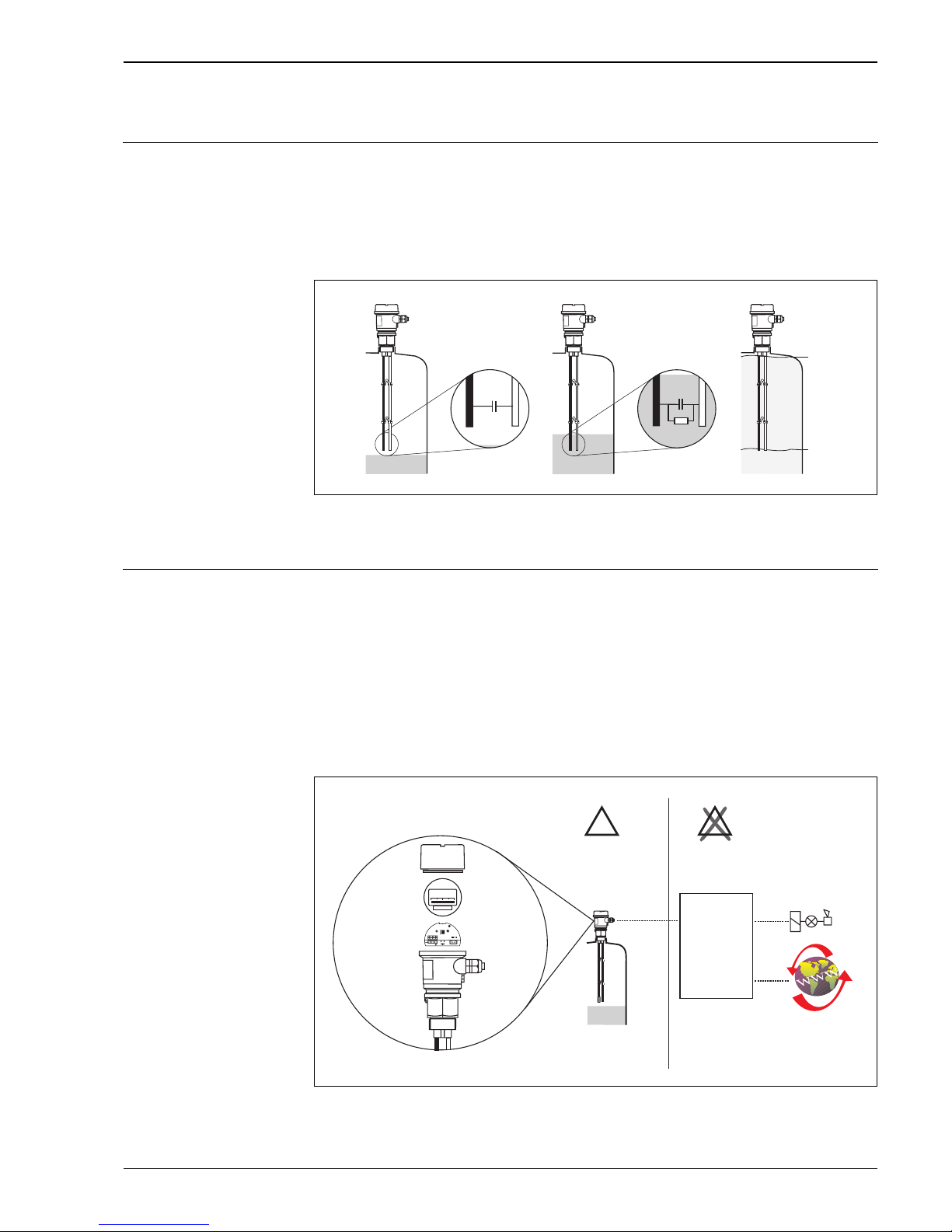
Measuring principle The probe, medium and ground rod (counter electrode) form an electric capacitor.
If the probe is in the air ➀, a certain low initial capacitance is measured.
When the tank is filled, the capacitance of the capacitor increases the more the probe is covered ➁ ➂.
As of a conductivity of 30 µs/cm, the measurement does not depend on the dc-value of the liquid.
The electronic insert of the probe converts the capacitance measured to a current, in proportion to the level,
in the range of 4...20 mA, thus making it possible to interpret the level.
All input and output channels are safely galvanically isolated from one another.
L00-FMI21xxx-15-05-xx-xx-001
CA : Initial capacitance (probe exposed)
C
E
: Final capacitance (probe covered)
Measuring system Probe with integrated electronic insert
The measuring system consists of:
• The components of a capacitive probe Liquicap T FMI21:
➀ Housing with two probe rods
(one probe rod fully insulated and the second uninsulated (ground potential))
➁ Electronic insert FEI20
➂ Display (optional)
➃ Housing cover (optional: cover with sight glass in conjunction with display)
• A transmitter power supply unit
L00-FMI21xxx-14-05-xx-en-000
mn o
C
A
R
C
C
C
E
A
E
X
E
X
–+
– +
FEI20
1 2
+ –
–
+
m
n
o
p
ATEX II 3G
RN221N
RNS221
RMA421
RMA422
FXA320
FMI21
0…100%
100,0
Remote
interrogation
Page 4
Liquicap T FMI21
4 Endress+Hauser
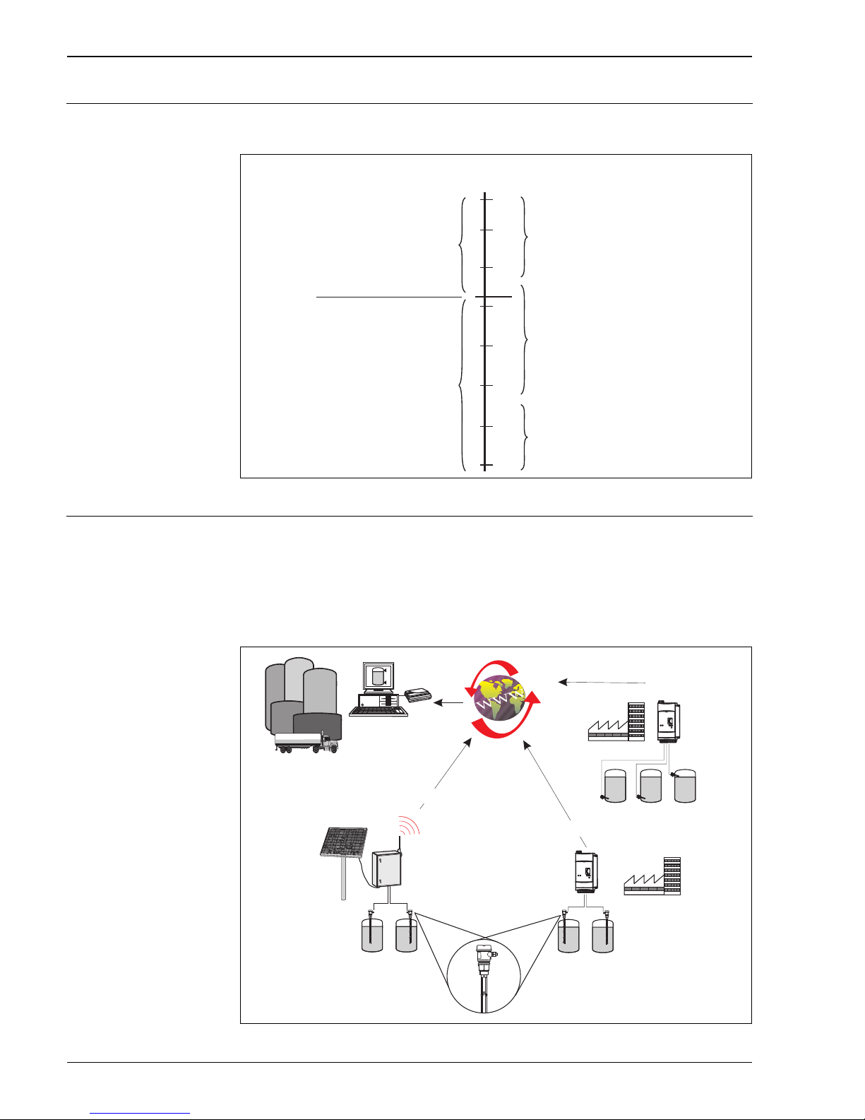
Operating medium Due to the probe design, the Liquicap T FMI21 can be used as of a conductivity of 30 µs/cm. The measurement
is independent of the dc-value and the conductivity of the liquid.
L00-FMI21xxx-05-06-xx-en-000
Applications Vendor Managed Inventory
The remote interrogation of tank or silo levels via Fieldgate enables suppliers of raw materials to gather
information about the current inventories of their regular customers at any time and, for example, take this into
account in their own production planning. The Fieldgate monitor the configured level limits and automatically
trigger the next delivery as required. Here, the spectrum of possibilities ranges from a simple purchasing
requisition by e-mail through to fully automatic order processing by incorporating XML data into the planning
systems on both sides.
L00-FMI21xxx-02-00-06-en-001
10
–3
10
–2
10
–1
1
10
10
2
10
3
10
4
30
Conductivity [µS/cm]
Liquicap T operating range
independent of the conductivity
and DK value (dielectric constant)
e.g. Hydrocarbons with
water contents below 0.1%,
petrols, oils, solvents
e.g. Hydrocarbons with
higher water contents,
demineralised water
e.g. Water-based liquids,
aqueous solutions of salts,
acids and alkalis,
aqueous dispersions and emulsions,
wastewater, electrolytes, beverages
Recommendation:
e.g. Multicap or Liquicap M
Levelflex M
Prosonic T/M
Micropilot M
Not suitable for Liquicap T
Fieldgate
FXA320
FMI21
Fieldgate
FXA320
Solar box with
FXA320
Solar panel
GSM
Vendor
Client A
Analog
4...20 mA
Analog
4...20 mA
Ethernet
Client B
Limit
switch
Telephone
Page 5

Liquicap T FMI21
Endress+Hauser 5
Input
Measured variable Continuous measurement of the change in capacitance between two probe rods depending on the level of a
conductive liquid. Maximum viscosity = 2000 cst
Measuring range The measuring range is between 150...2500 mm, depending on the probe length ordered.
• Probe length: 150...2500 mm
• Adjustable initial capacitance: C
A
= 0...2000 pF
• Permitted span: ∆C = 25...2000 pF
• End capacitance: C
E
= max. 2100 pF
• Measuring frequency: 250 kHz
Input signal Probes covered => high capacitance
Probes exposed => low capacitance
Output
Electronic insert FEI20
(4...20 mA)
Output signal
3.8...20.5 mA
Switch-on current
Max. 20 mA (< 500 ms)
Signal on alarm
> 21 mA
Page 6

Liquicap T FMI21
6 Endress+Hauser
Power supply
Electrical connection
(wiring diagram)
FMI21 with electronic insert FEI20 for connection to transmitter power supply units from Endress+Hauser.
L00-FMI21xxx-04-05-xx-en-000
Connection of the electronic insert FEI20
Transmitter power supply
units from Endress+Hauser
RNS221
Supply unit for supplying power to two 2-wire sensors or transmitters in the "non-Ex area".
RN221N
Active barrier with power supply for intrinsically safe separation of 4...20 mA standard signal circuits.
RMA421
Multi-functional 1-channel top-hat rail device with universal input, transmitter power supply, limit value
monitoring and analog output.
RMA422
Multi-functional 1-2-channel top-hat rail device with intrinsically safe current inputs and transmitter power
supply, limit value monitoring, mathematics functions and 1-2 analog outputs.
FXA320
Gateway to remote interrogation of sensors and actuators via Internet technology.
Supply voltage (FEI20) • Connection voltage: U = 10...30 V DC
• Reverse polarity protection (integrated)
Power consumption • P < 0.7 W
Current consumption • I < 22 mA
Cable entries M 20x1.5
• Degree of protection: IP66
• Number in F16 housing: 2 cable entries (1 cable gland included in scope of delivery)
NPT ½
• Number in F16 housing: 2 cable entries with dummy plugs
RN221N
RNS221
RMA421
RMA422
FXA320
– +
– +
FEI20
4...20 mA
12
+
–
–
+
10 %
0…100 %
99,0
Endress+Hauser
transmitter power supply
Remote interrogation
Page 7
Liquicap T FMI21
Endress+Hauser 7
Cable specifications Use usual commercial two-core or multi-core cable (25 Ω per core).
Cable cross-section (incl. ferrule): max. 2.5 mm
2
!
Note!
Use a screened cable in the event of strong, electromagnetic EMC condition.
Performance characteristics with installed electronic insert
Reference operating
conditions
• Ambient temperature: 23 °C
• Medium temperature: 23 °C
• Medium viscosity: medium must expose probe again (drain off < 2000 cst)
• Atmospheric pressure
• Probe installation: vertical from above
Maximum measured error ≤ 1 % of full scale value (active rod probe)
Repeatability 0.25 % of full scale value (range 0...2000 pF)
Start-up settling time < 2 s (stable measured value after switch-on process)
Influence of ambient
temperature
< 0.01 %/K (–40°C...+70 °C) probe length 1 m
Integration time τ =1 s (fixed)
The integration time affects the speed at which the display and the current output react to changes in the fluid
level.
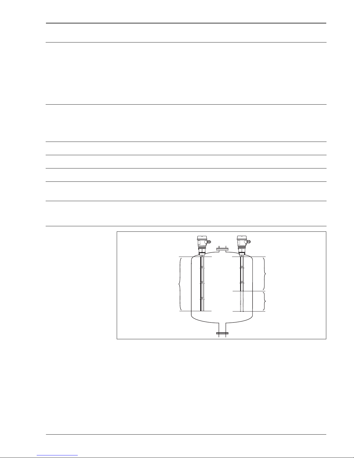
Factory calibration
L00-FMI21xxx-15-05-xx-en-000
Factory calibration: medium conductivity ≥ 30 µS/cm
Calibration accuracy 100 % max. -5 mm; 0 % max. -5 mm
In an installed state, recalibration is only necessary if
• The probe rods have been shortened
• The 0 % and 100 % value should be adjusted to suit customer specifications
• The electronic insert was changed
100 %
0%
Factory calibration
Recalibration
necessary
Shortening
Page 8
Liquicap T FMI21
8 Endress+Hauser
Installation
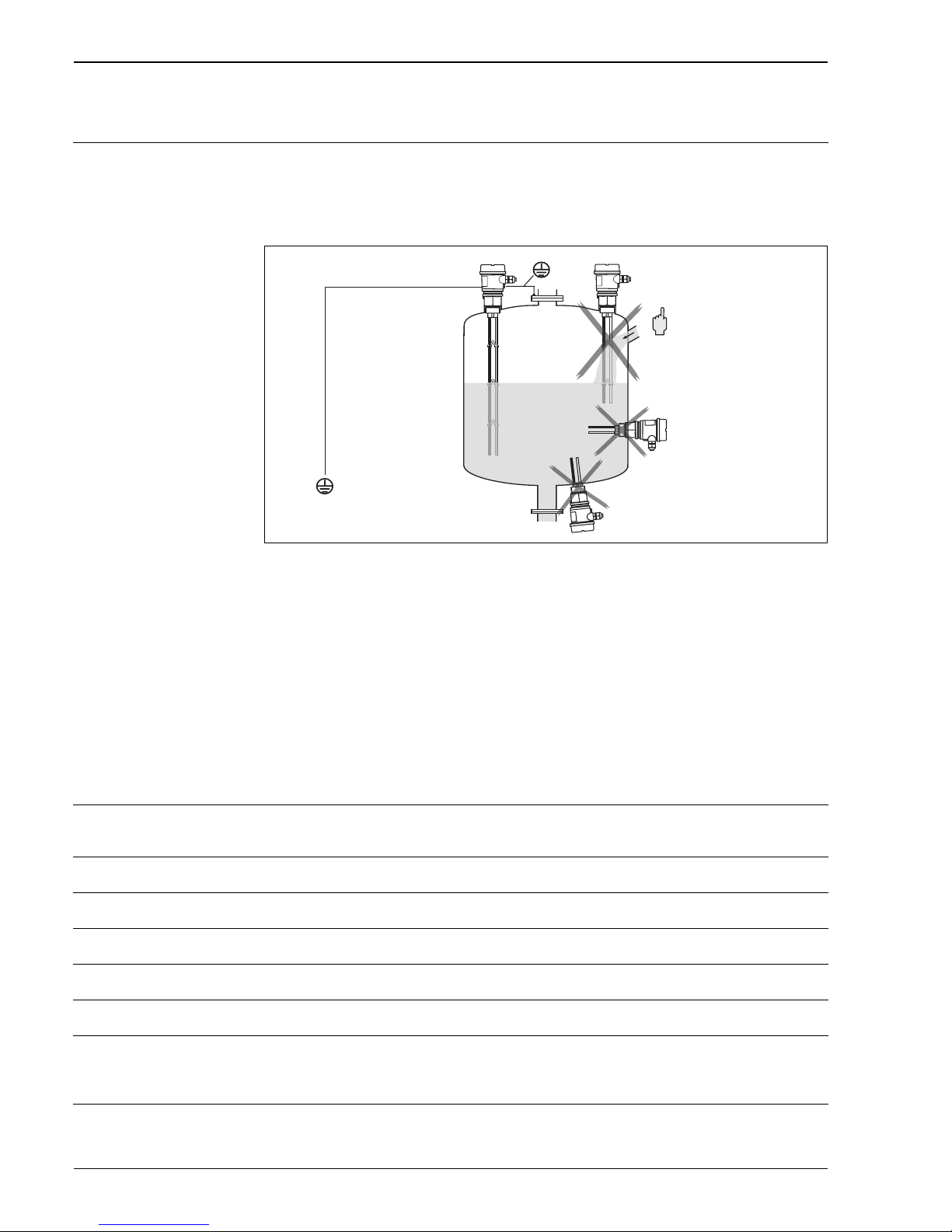
Installation instructions Mounting location
e.g. storage area and buffer tank.
Orientation (vertical)
L00-FMI21xxx-11-05-xx-xx-000
* Metal tank
** Plastic tank
!
Note!
The probe rods should never be in contact with the tank.
!
Note!
In the case of elevated electromagnetic radiation: protective ground should be attached to the device by a
possibly short line.
Environment
Ambient temperature range Ambient temperature for the electronic: -40...70 °C
The functionality of the display may be limited for temperatures Ta < –20 °C and Ta > +60 °C
Ambient temperature limits -40...80 °C (in limit range: restricted accuracy)
Storage temperature -40...80 °C
Climate class Suitable for the tropics as per DIN IEC 68 Part 2-38
Degree of protection IP66
Shock resistance DIN EN 60068-2-27 / IEC 68-2-27: 30 g
Vibration resistance
(with min. rod length
150 mm)
DIN EN 60068-2-64 / IEC 68-2-64: 20...2000 Hz, 1 (m/s
2)2
/Hz
Electromagnetic compatibility Interference emission to EN 61326, Electrical equipment Class B;
Interference immunity to EN 61326, Annex A (Industrial)
*
**
Page 9
Liquicap T FMI21
Endress+Hauser 9
Process
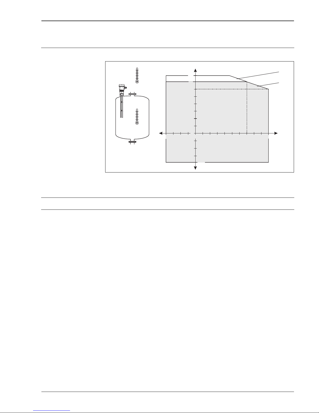
Environment Permitted ambient temperature Ta at the housing depending on the process temperature Tp in the tank:
L00-FMI21xxx-05-05-xx-xx-000
* Permitted work range
** Work range with restricted accuracy
Conductivity of medium ≥ 30 µS/cm
Process pressure –1...10 bar
50
40
30
20
10
–20–30 –10 10 30 40 50 60 7020 80 90
T
a
T
p
–10
–20
0
60
100–40
T
a
T
p
80
70
60
–30
–40
*
**
0
Page 10
Liquicap T FMI21
10 Endress+Hauser
Mechanical construction
!
Note!
All dimensions in mm (100 mm = 3.94 in)
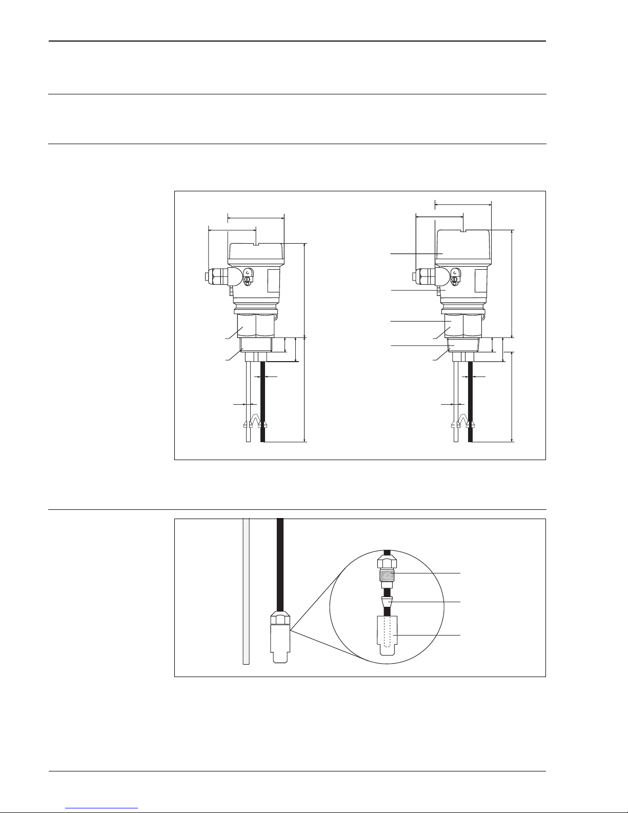
Design, dimensions Rod probe
Process connection with parallel thread G 1½ or with tapered thread NPT 1½.
L00-FMI21xxx-06-05-xx-en-000
* Ground rod (uninsulated)
** Probe rod insulated
Probe shortening set
L00-FMI21xxxx-17-06-xx-en-000
!
Note!
If shortening the probe rods, the insulation above the cut must not be damaged!
Recalibration is always necessary after shortening the probe. The active rod probe begins above the probe
shortening set. Therefore the zero balance should be carried out at this place. Only the insulated rod must be
insulated with the shortening set. The ground rod remains uninsulated.
max. 76
ø85
ø4
145
22
37
G1½
ø5
23.5
38.5
NPT 1½
max. 76
ø85
164
***
ø4
ø5
***
Probe length L
150…2500 mm
Probe length L
150…2500 mm
AF 55AF 55
Cover
Housing
Process connection
Adapter
Eye screw
Sealing ring
Insulating cap
Page 11

Liquicap T FMI21
Endress+Hauser 11
Weight Rod 1 m length
FMI21 = 600 g
Material Probe rods
• Rod: 1.4404/316L - (use in water-based media, alkalis ...)
Optional: carbon fibre CFC/rod retainer silver (Ag) - (use in acids e.g. hydrochloric acid)
• Insulation: PP
• Spacer: PP
• Probe shortening set: PP
Housing F16
• Housing: PBT-FR
•Cover: PBT
• Cover with sight glass: PA
• Cable gland: PA
• Adapter: PBT
• Dummy plug: PBT
Process connections
• G 1½ A (PPS, DIN ISO 228/l)
• NPT 1½ (PPS, ANSI B 1.20.1)
Seals
• Seal between housing and process connection: EPDM
• Seal for plastic housing cover F16: EPDM
• Sealing ring for process connection G 1½ A: elastomer fibre asbestos-free (resistant to oils,
solvents, steam, weak acids and alkalis)
Fitted electrodes Rod probe with two rods
• Rod diameter without insulation: 4 mm
• Maximum rod length: 2500 mm
• Minimum rod length: 150 mm
• Insulation thickness: 0.5 mm
• Extraction forces (parallel probe rod): 1000 N
• Lateral loading capacity: 2 Nm
Page 12
Liquicap T FMI21
12 Endress+Hauser
Human interface
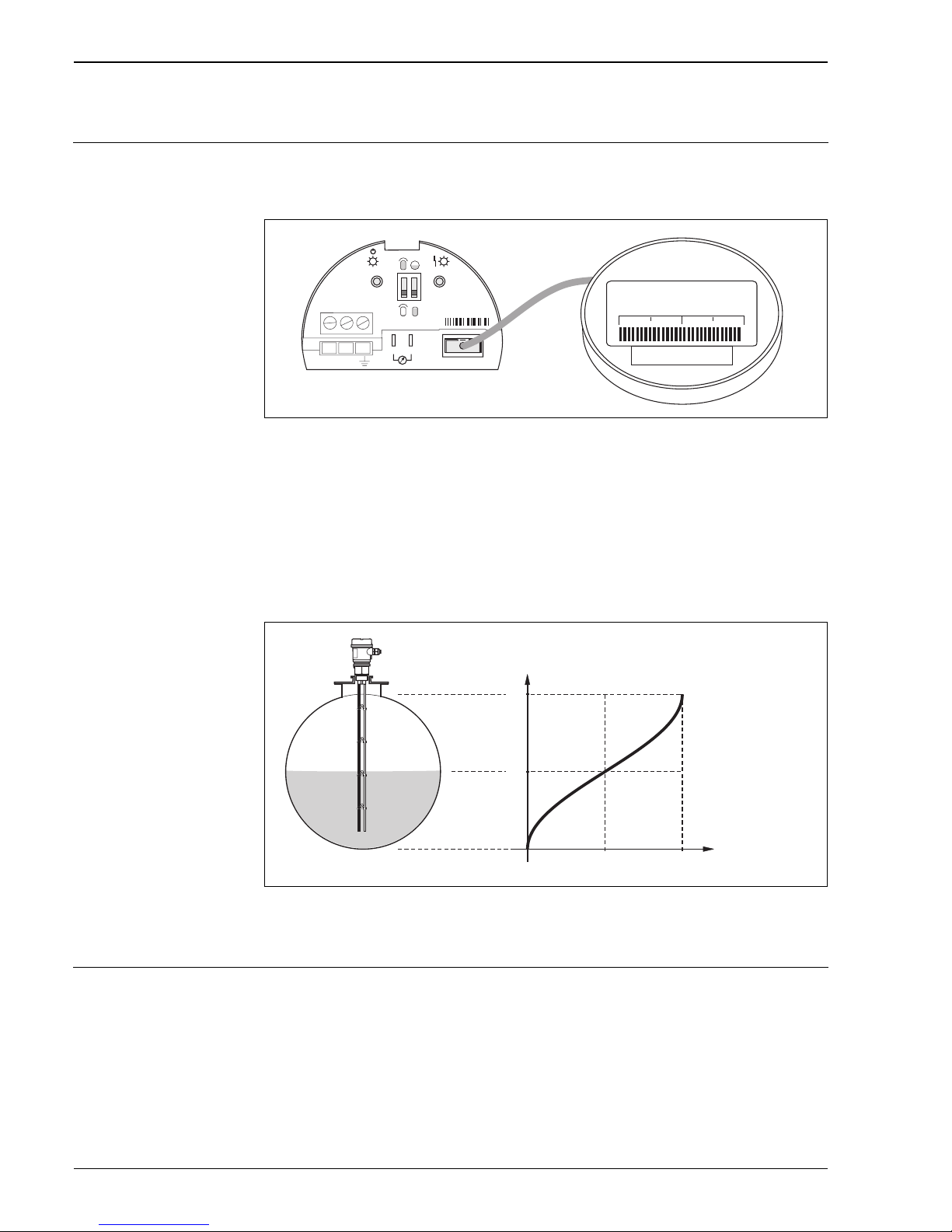
Operating elements Electronic insert FEI20
!
Note!
The display indicates no comma, if the probe length is < 200 mm.
L00-FMI21xxx-07-05-xx-xx-000
•Key (-)
•Key (+)
• 4...20 mA current pick-off, e.g. for full/empty calibration with multimeter.
(No need to disconnect circuit!)
• Display connection
• DIL switch (left) to determine calibration type (full/empty) of probe
• DIL switch (right) to switch linearisation on and off (only for horizontal cylindrical tanks)
Linearisation (for zylindrically lying tanks):
L00-FMI21xxx-15-05-xx-en-001
!
Note!
In zylindrically lying tanks the current output and display are in proportion to the volume.
Display elements FEI20
• A red light emitting diode: as alarm or warning (flashing)
• A green light emitting diode: to indicate operational status (flashes every 5 sec. approx.) or to confirm
key entries
• Display (optional) for measured value in %, bargraph for minimum and maximum probe capacitance.
– +
FEI20
4...20 mA
12
+
–
–
+
10 %
0…100 %
99,0
100 %
50 %
0%
0
0.5
(50 %)
1.0
(100 %)
0.5
1.0
Level
Current output/
display
Page 13

Liquicap T FMI21
Endress+Hauser 13
Certificates and approvals
CE mark The Liquicap T is in conformity with the statutory requirements of the EC Directives. Endress+Hauser confirms
that the device has been tested successfully by applying the CE mark.
CSA/US; General Purpose (GP) Kanada, USA
Overfill protection Approvals
• German Water Resources Law (WHG) - see commissioning notes in ZE263F (Z. 65.xx - xxx)
Other standards and
guidelines
• Low Voltage Directive (73/23/EEC)
• DIN EN 61010 Part 1, 2001
Protection Measures for Electrical Equipment for Measurement, Control, Regulation and Laboratory
Procedures.
Part 1: General Requirements
• CAN/CSA-C22.2 No. 1010.1-92
Safety Requirements for Electrical Equipment for Measurement, Control, and Laboratory Use;
Part 1: General Requirements (Includes Amendment 1)
• UL Std No. 61010C-1
Process Control Equipment; Part 1: General Requirements
• EN 61326
Electrical Equipment for Measurement, Control and Laboratory Use
EMC Requirements
• EN 50021
Electrical Apparatus for Potentially Explosive Atmospheres
Specification for Electrical Apparatus with Type of Protection "N"
Ex approval ATEXII3GEExnAIICT6
All explosion protection data are given in a separate documentation (see: Documentation) which is available
upon request.
Type of protection EEx nA IIC T6 (non-sparking equipment)
Page 14
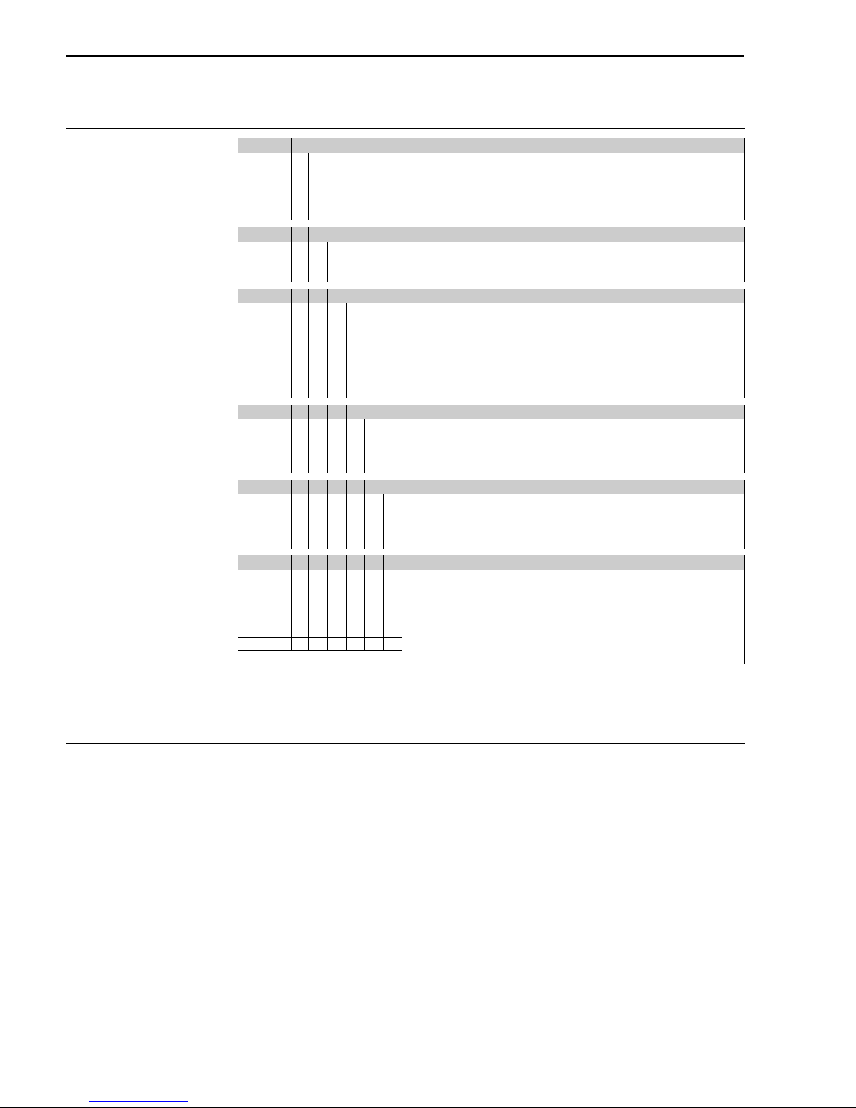
Liquicap T FMI21
14 Endress+Hauser
Ordering information
Liquicap T FMI21
Accessories
Liquicap T • Mounting nut G 1½
Hexagon head, AF 60
PN 52014146
• Shortening kit FMI21
PN 52024300
Spare parts • Electronics FEI20
PN 52025603
• Cover F16 high, transparent, with gasket
PN 52025605
• Cover F16 grey, PBTP, with gasket
PN 52025606
• Digital display, with holder
PN 52025604
• Spacer probe rods, 5 pieces
(5 pieces are included in the scope of delivery)
PN 52025607
10 Approval:
A Non-hazardous area
B Non-hazardous area, WHG
C ATEX II 3 G EEx nA IIC T6, WHG
D CSA General Purpose, CSA C US
Y Special version
20 Process Connection:
1 Thread ISO228 G 1½, PPS
2 Thread ANSI NPT 1½, PPS
9Special version
30 Probe Length; Material; 150...2500 mm (6...100 inch):
A ... mm L, PP 316L
B ... mm L, PP carbon fiber (< 1000 mm)
C ... mm L, PP carbon fiber (> 1000 mm)
D ... inch L, PP 316L
E ... inch L, PP carbon fiber (< 40 inch)
F ... inch L, PP carbon fiber (> 40 inch)
YSpecial version
40 Housing; Cable Entry:
1 F16 polyester IP66 NEMA4X; gland M20
2 F16 polyester IP66 NEMA4X; thread NPT ½
3 F16 polyester IP66 NEMA4X; thread G ½
9Special version
50 Electronics; Output:
ANone
B FEI20; 4...20 mA
C FEI20; 4...20 mA + display
YSpecial version
60 Additional Option:
1 Basic version
2Shortening kit PP
9 Special version
FMI21 Complete product designation
Page 15

Liquicap T FMI21
Endress+Hauser 15
Documentation
!
Note!
The specified documentations are available under www.endress.com.
Technical Information • Gateways / interfaces
Fieldgate FXA320
TI369F/00
• Process transmitter
Preline RMA422
TI072R/09
• Process transmitter
Preline RMA421
TI064R/09
• Transmitter power supply unit
Preline RNS221
TI081R/09
• Active barrier
Preline RN221N
TI073R/09
Operating Instructions • Liquicap T FMI20
KA233F/00
Certificates WHG (German Water Resources Law)
• Liquicap T
ZE263F/00
ATEX
• Liquicap T
II 3 G EEx nA IIC T6
XA320F/00
Page 16

Liquicap T FMI21
International Head Quarter
Endress+Hauser
GmbH+Co. KG
Instruments International
Colmarer Str. 6
79576 Weil am Rhein
Deutschland
Tel. +49 76 21 9 75 02
Fax +49 76 21 9 75 34 5
www.endress.com
[email protected]
TI393F/00/en/04.05
SL/FM+SGML6.0 ProMoDo
 Loading...